WO2024166393A1 - 情報生成システム - Google Patents
情報生成システム Download PDFInfo
- Publication number
- WO2024166393A1 WO2024166393A1 PCT/JP2023/004647 JP2023004647W WO2024166393A1 WO 2024166393 A1 WO2024166393 A1 WO 2024166393A1 JP 2023004647 W JP2023004647 W JP 2023004647W WO 2024166393 A1 WO2024166393 A1 WO 2024166393A1
- Authority
- WO
- WIPO (PCT)
- Prior art keywords
- dimensional
- information
- marker
- imaging device
- figures
- Prior art date
- Legal status (The legal status is an assumption and is not a legal conclusion. Google has not performed a legal analysis and makes no representation as to the accuracy of the status listed.)
- Ceased
Links
Images


Classifications
-
- G—PHYSICS
- G01—MEASURING; TESTING
- G01B—MEASURING LENGTH, THICKNESS OR SIMILAR LINEAR DIMENSIONS; MEASURING ANGLES; MEASURING AREAS; MEASURING IRREGULARITIES OF SURFACES OR CONTOURS
- G01B11/00—Measuring arrangements characterised by the use of optical techniques
-
- G—PHYSICS
- G01—MEASURING; TESTING
- G01C—MEASURING DISTANCES, LEVELS OR BEARINGS; SURVEYING; NAVIGATION; GYROSCOPIC INSTRUMENTS; PHOTOGRAMMETRY OR VIDEOGRAMMETRY
- G01C15/00—Surveying instruments or accessories not provided for in groups G01C1/00 - G01C13/00
-
- G—PHYSICS
- G01—MEASURING; TESTING
- G01C—MEASURING DISTANCES, LEVELS OR BEARINGS; SURVEYING; NAVIGATION; GYROSCOPIC INSTRUMENTS; PHOTOGRAMMETRY OR VIDEOGRAMMETRY
- G01C15/00—Surveying instruments or accessories not provided for in groups G01C1/00 - G01C13/00
- G01C15/02—Means for marking measuring points
- G01C15/06—Surveyors' staffs; Movable markers
Definitions
- This invention relates to a marker that can be read using an imaging device, and a system that uses the marker.
- mobile robots also called mobile manipulators
- manipulators that use manipulators to perform specific tasks
- Examples of tasks that can be performed by such mobile robots include removing and transporting containers, cases, etc. stored on shelves in a warehouse, or storing transported containers, cases, etc. on shelves.
- a camera provided on the manipulator or the main body, etc. may be used to recognize markers on the work target to determine positioning and perform the work with high precision.
- Patent Document 1 discloses a technology in which a visual sensor captures an image of one of two-dimensional markers placed at the four corners of a test tube rack, and calculates the position information in the sensor coordinate system of the center of the opening of a test tube in the test tube rack.
- a blank area large enough to arrange at least a square of an appropriate size for the two-dimensional marker is required on the surface of a shelf or the like on which work objects are stored.
- blank areas are provided at the four corners of a test tube rack, and square two-dimensional markers are arranged in each of these areas.
- the present invention has been made in consideration of the above-mentioned technical background, and its purpose is to perform highly accurate positioning between a marker and an imaging device even in situations where the placement area of the marker on the target object is limited.
- the information generation system of the present invention includes a one-dimensional marker configured by arranging two or more types of element figures in a row, with adjacent element figures encoding unique position information in units of a predetermined number, an imaging device that generates an image by imaging the adjacent element figures in units of the predetermined number or more, and an information generation unit that generates three-dimensional position information indicating the relative positional relationship in three-dimensional space between the imaging device and the one-dimensional marker based on the image.
- the one-dimensional marker is configured so that it can be attached to a specific object.
- This configuration allows for highly accurate positioning between a specific object to which a marker is attached and the imaging device.
- the element figures may be arranged at equal intervals.
- This configuration makes it easier to recognize the marker.
- the virtual bounding figures of the element figures may all be squares.
- the element figure may be, for example, a square, a circle, etc.
- All of the above element shapes may be circular.
- This configuration makes it easy to calculate the center position of the element graphic through image processing, improving the accuracy of marker recognition.
- the element figures may include a first figure that is an entirely black circle, and a second figure that is a black annular figure with a white center.
- the imaging device may be a monocular camera.
- This configuration can reduce costs.
- the information generating unit may generate the three-dimensional position information by calculating the three-dimensional position of each of the element figures of the one-dimensional marker and the orientation of the longitudinal axis of the one-dimensional marker based on the image.
- the information generating unit may calculate the three-dimensional position and the direction of the axis based on optical parameters related to the imaging device, the distance between the element figures, and the pixel positions of the element figures on the image.
- the imaging device may be a stereo camera.
- the information generating unit may generate the three-dimensional position information by using parallax information based on a set of images acquired using the stereo camera.
- the information generation system may further include a movable base and a manipulator attached to the base, and the imaging device may be attached to the manipulator.
- the imaging device can be placed in the desired position and orientation by operating the manipulator.
- the information generation system may further include a movable base and a manipulator attached to the base, and the imaging device may be attached to the base.
- the one-dimensional marker can be placed near the base.
- the present invention is a system comprising a one-dimensional marker configured by arranging two or more types of element figures in a row, with adjacent element figures encoding unique position information in units of a predetermined number, and a mobile manipulator, the mobile manipulator comprising a movable base, a multi-joint manipulator attached to the base, an imaging device attached to the multi-joint manipulator and generating an image by capturing images of the adjacent element figures in units of the predetermined number or more, and an information generating unit that generates three-dimensional position information indicating the relative positional relationship in three-dimensional space between the imaging device and the one-dimensional marker based on the image.
- the present invention it is possible to perform highly accurate positioning between the marker and the imaging device even in situations where the area on the object where the marker can be placed is limited.
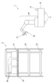
- FIG. 1 is a diagram showing the overall configuration of a system including a mobile manipulator and a shelf.
- FIG. 2 is an explanatory diagram of a one-dimensional marker.
- FIG. 3 is a general flowchart of the operation of the mobile manipulator when retrieving a target object from a shelf.
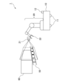
- FIG. 4 is a conceptual diagram showing the mobile manipulator after the camera has been moved.
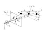
- FIG. 5 is an explanatory diagram showing the relationship between a camera, an image plane (P) related to the camera, and element figures constituting a one-dimensional marker.
- FIG. 6 is an explanatory diagram regarding transformation of a coordinate system.
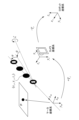
- FIG. 7 is a diagram showing the principle of capturing an image of an element figure by a stereo camera (second embodiment).
- FIG. 8 is a diagram showing the principle of imaging an element figure using a pinhole camera model (second embodiment).
- First embodiment As a first embodiment, an operation (or task) will be described in which the mobile manipulator 1 recognizes a one-dimensional marker 55 attached to a shelf 5 and picks up an object 60 on a shelf board 51 with high accuracy. As will be apparent to those skilled in the art, placing an object 60 on the shelf board 51 can also be performed by substantially the same process.
- the present invention can be applied to any situation in which it is necessary to determine the relative positional relationship between a camera and a marker. Therefore, it is of course applicable to various other objects as well. For example, it can be applied to robots that do not have a moving function or robots that do not have a manipulator.
- (1.1 System Configuration) 1 is an overall configuration diagram of a system including a mobile manipulator 1 and a shelf 5.
- the mobile manipulator 1 includes a base 10 and a multi-joint robot arm 20 attached to the top surface of the base 10.
- a moving mechanism 11 is provided on the bottom surface of the base 10, and a LiDAR unit 12 is provided at the rear end of the top surface of the base 10.
- An information processing device is provided inside the base 10 (not shown) and controls the mobile manipulator 1.
- the moving mechanism 11 is an omnidirectional moving mechanism. This moving mechanism allows the mobile manipulator to move in any direction.
- an omniwheel is used as the omnidirectional moving mechanism.
- this embodiment employs an omni-wheel as a mechanism for moving in all directions
- the present invention is not limited to this configuration. Therefore, other configurations that enable omnidirectional movement, such as a Mecanum wheel, may also be employed.
- the movement mechanism is not limited to an omnidirectional movement mechanism. Therefore, other movement mechanisms with limited movement orientations and directions (such as a light race using a differential two-wheel mechanism) may also be employed.
- the mechanism is not limited to one that moves on the ground, but may be one that moves while suspended from the ceiling or one that moves through the air by flying.
- the LiDAR unit 12 uses laser light to detect the distance and direction to surrounding objects, and can autonomously move through the environment using this LiDAR unit 12. Although the LiDAR unit 12 is used as the environmental detection means, other sensor units may also be used.
- the robot arm 20 has multiple drive joints, and is equipped with a gripper 22 at its tip. With this configuration, the robot arm 20 can reach a target position from any angle and grasp or release an object 60 with the gripper.
- a camera 21 is provided at a predetermined angle near the gripper 22 and is used to recognize the object or the section on which the object is placed, or to recognize a one-dimensional marker 55, which will be described later.
- This camera 21 recognizes the one-dimensional marker 55 and performs the processing described later, making it possible to perform highly accurate positioning.
- the camera 21 is a monocular camera. This camera 21 may also be attached to the base 10.
- a configuration equipped with such a monocular camera can reduce costs compared to a stereo camera, etc.
- the information processing device includes a control unit consisting of a CPU or the like that executes programs, a storage unit consisting of a ROM, RAM, flash memory, etc. that stores programs and data described below, and a communication unit, which are connected via a bus.
- the storage unit stores information required to perform various processes described below, such as information about the target (target object or target position), information about the height of the shelf board 51 to which the one-dimensional marker 55 is attached, code information for matching, optical parameters related to the camera 21, and information about the kinematics of the mobile manipulator 1.
- the information processing device is connected to actuators (not shown) and various sensors (not shown) provided at each joint of the robot arm 20, the camera 21, the gripper 22, the moving mechanism 11, the LiDAR unit 12, etc., and transmits and receives information between these devices and controls these devices.
- shelf 5 is a three-tiered shelf having three shelves (51-53), and three objects 60 are placed at regular intervals on top shelf 51.
- objects 60 are containers, and various objects are stored inside the containers. Note that objects 60 do not have to be containers, and can be set arbitrarily depending on the task.
- a one-dimensional marker 55 is horizontally arranged on the side surface of the top shelf 51 facing the mobile manipulator 1.
- This shelf 51 is constructed with a small thickness, and is therefore not suitable for arranging a two-dimensional marker.
- the side surface of the shelf 15 is a long and narrow surface (or a strip-shaped surface) in which there is a sufficient area on its long side (the longitudinal direction of the shelf 51) for arranging a marker, but there is not enough of such an area on the short side (the thickness direction of the shelf 51) perpendicular to the long side, and the length of the short side is smaller than the length of one side of a two-dimensional marker large enough to be recognized by imaging.
- the relative positional relationship between the camera 21 and the one-dimensional marker 55 can be determined by imaging the one-dimensional marker 55 using the camera 21.
- FIG. 2 is an explanatory diagram of a one-dimensional marker 55.
- the one-dimensional marker 55 is a band-shaped marker made up of a total of 16 elements of two types of figures arranged in a straight line: a first element figure that is a black circle in its entirety, and a second element figure that is a black annular figure with a white center.
- the spacing between these element figures is constant.
- This one-dimensional marker 55 represents a unique pattern when four adjacent consecutive element figures are extracted, and so encodes the unique position information (ID) of the element figures in units of four element figures.
- ID unique position information
- a sequence in which a unique pattern is observed by observing a predetermined number of adjacent figures in this way is sometimes called a De Brujin sequence. For example, in the example of Figure 2, if the pattern "(first element figure) ⁇ (first element figure) ⁇ (second element figure) ⁇ (second element figure)" is extracted, it can be uniquely identified that element figures with IDs of 5 to 8 have been extracted.
- the one-dimensional marker is a long, thin strip with multiple element figures arranged on a white background, and can be attached to any target object.
- the attachment method may be, for example, pasting like a sticker, or fixing with a fastener such as a bolt. It is not necessary to make all the element figures into a strip as a set; for example, the element figures may be printed directly on the target object, or the element figures may be represented by coloring.
- the markers can be easily attached, making it easy to perform highly accurate positioning between a specified object and the imaging device.
- the virtual circumscribing figure of the element figure is a square.
- a square can be used as the shape of another element figure whose virtual circumscribing figure is a square.
- (1.2 Mobile manipulator operation) 3 is a general flowchart regarding the operation of the mobile manipulator 1 when taking out a target object 60 from the shelf 5. Note that the mobile manipulator 1 may determine itself which object or position in space is to be the target, or it may be provided by an external device such as a host system or another device.
- the mobile manipulator 1 controls the movement mechanism 11 to move autonomously and move in front of the target object 60, that is, in front of the shelf 5 that stores the object 60 (S11).
- the autonomous movement may be performed by estimating the self-position by comparing a pre-stored environmental map with the detection results of the LiDAR unit 12.
- the mobile manipulator 1 controls the robot arm 20 to move the camera 21 so that at least a predetermined number of element figures are included within the angle of view.
- the process of moving the camera 21 may be, for example, a process of moving the tip of the robot arm 20 to the height of the shelf board 51 to which the one-dimensional marker 55 is attached, which is stored in advance.
- the predetermined number is four, which is the unit for encoding unique position information.
- FIG. 4 is a conceptual diagram showing the mobile manipulator 1 after the camera 21 has been moved. As shown in the figure, by controlling the robot arm 20, the camera 21 is oriented horizontally and faces the one-dimensional marker 55 directly. In addition, the angle of view of the camera 21 includes four element figures of the one-dimensional marker 55.
- the mobile manipulator 1 captures an image using the camera 21 and acquires the image (S13).
- the mobile manipulator 1 decodes a portion of the one-dimensional marker 55 from the acquired image and acquires the coded information, i.e., the ID of each element graphic (S13).
- the control unit of the information processing device provided in the mobile manipulator 1 detects the central pixel position (u i , v i ) of each element figure from a two-dimensional camera-acquired image by a known ellipse detection method (where i represents an ID number). Then, the control unit determines whether each element figure is a black circle (first element figure) or a black annular figure with a white center (second element figure). Then, the control unit collates pre-stored code information (in this embodiment, a known De Brujin Sequence) with the element figure in the image to identify the ID of each element figure.
- a known Brujin Sequence pre-stored code information
- the mobile manipulator 1 uses the central pixel position (u i , v i ) of each element figure and the pinhole camera model to calculate the three-dimensional position of each element figure of the one-dimensional marker 55 and the direction of the longitudinal axis of the one-dimensional marker 55 (S15).
- the longitudinal axis is a straight line passing through the center of each element figure constituting the one-dimensional marker 55.
- FIG. 5 is an explanatory diagram showing the relationship between the camera 21, the image plane (P) related to the camera 21, and element figures constituting the one-dimensional marker 55.
- the element figures are referred to as m1 , m, and m2 from the left.
- ( xc , yc , zc ) represents the coordinate system of the camera 21.
- (u, v) represents the pixel position on the two-dimensional image plane.
- (x, y, z) represent the three-dimensional position of element figure m in the camera coordinate system.
- ⁇ represents the amount of rotation of the longitudinal axis around the yc axis
- ⁇ represents the amount of rotation around the zc axis.
- L represents the distance between the center coordinates of the element figures.
- a pinhole camera model is used for the camera 21.
- the rotation around the xc axis ( ⁇ (see FIG. 6)
- f is a pre-stored optical parameter, specifically, the focal length of the lens divided by the physical size of one pixel on the sensor.
- Equation 2 Since the central pixel position (u1, u, u2, v1, v, v2) of each element shape is known, solving Equation 2 for ⁇ gives the following:
- the orientation ( ⁇ , ⁇ ) of the longitudinal axis of the one-dimensional marker 55 can be calculated.
- the three-dimensional position of the element figure can be expressed as follows using the two-dimensional central pixel position (u, v) and the optical parameter f.
- the two-dimensional central pixel position (u, v) can be obtained
- the three-dimensional position (x, y, z) in the camera coordinate system of each element figure that makes up the one-dimensional marker 55 can be obtained.
- the above calculations may be performed each time, or only the final calculation formula (e.g., formulas 3, 4, 5, and 6) may be stored and the three-dimensional position of each element graphic may be calculated appropriately from the pixel position.
- the final calculation formula e.g., formulas 3, 4, 5, and 6
- the mobile manipulator 1 calculates a homogeneous transformation matrix mTc from the marker coordinate system to the camera coordinate system based on the information on the orientation of the axis ( ⁇ , ⁇ ) (S16).
- Various known methods can be used to calculate the homogeneous transformation matrix.
- the mobile manipulator 1 calculates a homogeneous transformation matrix cTr from the camera coordinate system to the robot coordinate system based on the kinematics based on the structure of the mobile manipulator 1.
- Various known methods can be used to calculate this homogeneous transformation matrix.
- the position and orientation of the target section expressed in the marker coordinate system stored in advance are transformed using the two homogeneous transformation matrices mTc, cTr to convert them into values in the robot coordinate system (S17).
- FIG. 6 is an explanatory diagram regarding transformation of a coordinate system.
- ( xm , ym , zm ) represents the marker coordinate system.
- ( xc , yc , zc ) represents the camera coordinate system.
- ( xr , yr , zr ) represents the robot coordinate system.
- the origin of the marker coordinate system is located at a predetermined position on the longitudinal axis of the one-dimensional marker 55, in particular, at the center position of the element graphic with an ID of 0.
- the position and orientation (P) of the target area is defined in the marker coordinate system.
- the position and orientation defined in the marker coordinate system can be converted into the camera coordinate system or the robot coordinate system, allowing tasks to be performed with high precision.
- control unit controls the robot arm 20 based on the position and orientation (P) of the target area in the robot coordinate system to perform a process of picking up the object 60 that is at a predetermined position and orientation in the target area using the gripper 22 (S18). After this operation, the object pick-up operation is completed.
- the one-dimensional marker 55 can be used to calculate the relative positional relationship in three-dimensional space between the camera 21 and the one-dimensional marker 55.
- highly accurate positioning between the one-dimensional marker 55 and the camera 21 can be performed.
- Second embodiment In the first embodiment, a monocular camera is used as the camera 21. In the present embodiment, an example in which a stereo camera is used as the camera 21 will be described.
- the configuration of the mobile manipulator 1 in this embodiment is substantially the same as that in the first embodiment, except that the camera 21 is a stereo camera, so a detailed description will be omitted (see Figures 1 and 2).
- the operation of the mobile manipulator 1 is also substantially the same, except that the method of calculating the three-dimensional position of each element figure and the axial direction of the one-dimensional marker 55 (S15) is different because the camera 21 is a stereo camera. Therefore, only the method of calculating the three-dimensional position of each element figure and the axial direction of the one-dimensional marker 55 using the camera 21, which is a stereo camera, will be described in detail.
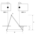
- Figure 7 shows the principle of capturing images of elemental figures using a stereo camera.
- the left and right camera positions are depicted as points at the bottom of the figure, and the distance between the left and right cameras is represented by B.
- the cameras are arranged parallel to each other on the same plane.
- the two cameras may be physically arranged parallel to each other, or a mathematical parallelization process may be performed.
- the depth Z can be expressed as follows using the camera distance B and focal length f:
- the depth Z can be obtained from the pixel positions (u L , u R ) of the left and right cameras 21, the known inter-camera distance B, and the focal length f.
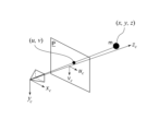
- Fig. 8 is a diagram showing the principle of capturing an image of an element figure using a pinhole camera model.
- ( xc , yc , zc ) represents the coordinate system of the camera 21.
- (u, v) represents the pixel position on the two-dimensional image plane.
- (x, y, z) represents the three-dimensional position of the element figure in the camera coordinate system.
- the three-dimensional position of the element figure, the amount of rotation ⁇ around the yc- axis, and the amount of rotation ⁇ around the zc - axis can be obtained, and then, as in the first embodiment, the homogeneous transformation matrix mTc from the marker coordinate system to the camera coordinate system, etc. can be obtained.
- the stereo camera can be used to recognize element shapes with high accuracy, thereby improving the accuracy of the work.
- the element figures of the one-dimensional marker 55 are circular, but the present invention is not limited to such a configuration. Figures may have any shape, pattern, or color as long as they are distinguishable from one another.
- a one-dimensional code using two types of element figures is configured to encode unique information using four element figures, but the present invention is not limited to such a configuration. Therefore, for example, information may be encoded using a number of other element figures. Also, three or more types of figures may be used as the types of element figures.
- the present invention can be used in industries that manufacture markers or systems that use markers.
- Mobile manipulator 10 Base (base part) 11: moving mechanism 12: LiDAR unit 20: robot arm 21: camera 22: gripper 5: shelf 51: shelf board (upper level) 52 Shelf (interrupted) 53 Shelf (lower) 55 Marker (1D marker) 60 Object
Landscapes
- Physics & Mathematics (AREA)
- General Physics & Mathematics (AREA)
- Engineering & Computer Science (AREA)
- Radar, Positioning & Navigation (AREA)
- Remote Sensing (AREA)
- Length Measuring Devices By Optical Means (AREA)
Priority Applications (2)
| Application Number | Priority Date | Filing Date | Title |
|---|---|---|---|
| JP2024576076A JPWO2024166393A1 (enExample) | 2023-02-10 | 2023-02-10 | |
| PCT/JP2023/004647 WO2024166393A1 (ja) | 2023-02-10 | 2023-02-10 | 情報生成システム |
Applications Claiming Priority (1)
| Application Number | Priority Date | Filing Date | Title |
|---|---|---|---|
| PCT/JP2023/004647 WO2024166393A1 (ja) | 2023-02-10 | 2023-02-10 | 情報生成システム |
Publications (1)
| Publication Number | Publication Date |
|---|---|
| WO2024166393A1 true WO2024166393A1 (ja) | 2024-08-15 |
Family
ID=92262752
Family Applications (1)
| Application Number | Title | Priority Date | Filing Date |
|---|---|---|---|
| PCT/JP2023/004647 Ceased WO2024166393A1 (ja) | 2023-02-10 | 2023-02-10 | 情報生成システム |
Country Status (2)
| Country | Link |
|---|---|
| JP (1) | JPWO2024166393A1 (enExample) |
| WO (1) | WO2024166393A1 (enExample) |
Citations (3)
| Publication number | Priority date | Publication date | Assignee | Title |
|---|---|---|---|---|
| JP2002090118A (ja) * | 2000-09-19 | 2002-03-27 | Olympus Optical Co Ltd | 3次元位置姿勢センシング装置 |
| JP2007271563A (ja) * | 2006-03-31 | 2007-10-18 | Canon Inc | 位置姿勢計測方法及び装置 |
| JP2013205278A (ja) * | 2012-03-29 | 2013-10-07 | Denso It Laboratory Inc | 測位用マーカおよび撮像装置の位置・姿勢推定システム |
-
2023
- 2023-02-10 WO PCT/JP2023/004647 patent/WO2024166393A1/ja not_active Ceased
- 2023-02-10 JP JP2024576076A patent/JPWO2024166393A1/ja active Pending
Patent Citations (3)
| Publication number | Priority date | Publication date | Assignee | Title |
|---|---|---|---|---|
| JP2002090118A (ja) * | 2000-09-19 | 2002-03-27 | Olympus Optical Co Ltd | 3次元位置姿勢センシング装置 |
| JP2007271563A (ja) * | 2006-03-31 | 2007-10-18 | Canon Inc | 位置姿勢計測方法及び装置 |
| JP2013205278A (ja) * | 2012-03-29 | 2013-10-07 | Denso It Laboratory Inc | 測位用マーカおよび撮像装置の位置・姿勢推定システム |
Also Published As
| Publication number | Publication date |
|---|---|
| JPWO2024166393A1 (enExample) | 2024-08-15 |
Similar Documents
| Publication | Publication Date | Title |
|---|---|---|
| JP7284953B2 (ja) | 高度化したスキャンメカニズムを有するロボットシステム | |
| CN105518486B (zh) | 追踪可移动目标物体的方位的系统和方法 | |
| US11584004B2 (en) | Autonomous object learning by robots triggered by remote operators | |
| US9630321B2 (en) | Continuous updating of plan for robotic object manipulation based on received sensor data | |
| US9424470B1 (en) | Systems and methods for scale invariant 3D object detection leveraging processor architecture | |
| JP6855492B2 (ja) | ロボットシステム、ロボットシステム制御装置、およびロボットシステム制御方法 | |
| KR101581197B1 (ko) | 로봇 및 그 제어방법 | |
| Nigro et al. | Peg-in-hole using 3D workpiece reconstruction and CNN-based hole detection | |
| JP2016099257A (ja) | 情報処理装置及び情報処理方法 | |
| JP7180783B2 (ja) | コンピュータビジョンシステムのキャリブレーション方法及びこれに用いる基準立体物 | |
| CN113485350A (zh) | 一种机器人移动控制方法、装置、设备及存储介质 | |
| US12222196B2 (en) | Measurement system, measurement device, measurement method, and measurement program | |
| KR102452315B1 (ko) | 딥러닝과 마커를 이용한 비전인식을 통한 로봇 제어장치 및 그 방법 | |
| CN107291072B (zh) | 一种移动机器人路径规划系统及方法 | |
| JP7475663B2 (ja) | モバイルマニピュレータ及びその制御方法及びプログラム | |
| EP4094904B1 (en) | Robot system control device, robot system control method, computer control program, and robot system | |
| CN112074706B (zh) | 精确定位系统 | |
| US12196859B2 (en) | Label transfer between data from multiple sensors | |
| WO2024166393A1 (ja) | 情報生成システム | |
| CN111516006B (zh) | 一种基于视觉的复合机器人作业方法及系统 | |
| CN111598945B (zh) | 一种汽车发动机曲轴瓦盖的三维定位方法 | |
| TWI788253B (zh) | 適應性移動操作設備及方法 | |
| Cofield et al. | A humanoid robot object perception approach using depth images | |
| JP7633423B2 (ja) | 学習データの生成装置および学習データの生成方法、並びに学習データを使用する機械学習装置および機械学習方法 | |
| JP4892687B2 (ja) | 物体検出方法 |
Legal Events
| Date | Code | Title | Description |
|---|---|---|---|
| 121 | Ep: the epo has been informed by wipo that ep was designated in this application |
Ref document number: 23921222 Country of ref document: EP Kind code of ref document: A1 |
|
| WWE | Wipo information: entry into national phase |
Ref document number: 2024576076 Country of ref document: JP |
|
| NENP | Non-entry into the national phase |
Ref country code: DE |