WO2024166374A1 - フラッシュバット溶接レールの製造方法 - Google Patents
フラッシュバット溶接レールの製造方法 Download PDFInfo
- Publication number
- WO2024166374A1 WO2024166374A1 PCT/JP2023/004601 JP2023004601W WO2024166374A1 WO 2024166374 A1 WO2024166374 A1 WO 2024166374A1 JP 2023004601 W JP2023004601 W JP 2023004601W WO 2024166374 A1 WO2024166374 A1 WO 2024166374A1
- Authority
- WO
- WIPO (PCT)
- Prior art keywords
- flash
- pulse
- rail
- rails
- current
- Prior art date
- Legal status (The legal status is an assumption and is not a legal conclusion. Google has not performed a legal analysis and makes no representation as to the accuracy of the status listed.)
- Ceased
Links
Images






Classifications
-
- B—PERFORMING OPERATIONS; TRANSPORTING
- B23—MACHINE TOOLS; METAL-WORKING NOT OTHERWISE PROVIDED FOR
- B23K—SOLDERING OR UNSOLDERING; WELDING; CLADDING OR PLATING BY SOLDERING OR WELDING; CUTTING BY APPLYING HEAT LOCALLY, e.g. FLAME CUTTING; WORKING BY LASER BEAM
- B23K11/00—Resistance welding; Severing by resistance heating
- B23K11/04—Flash butt welding
Definitions
- the present invention relates to a method for manufacturing flash butt welded rails.
- FB welding flash butt
- Rails shipped from the rail manufacturer are welded at the railway company's welding factory using a stationary FB welding machine (fixed FB welding machine), which produces long rails, for example, over 200 meters long. These long rails are then transported to the installation site and further welded using a portable FB welding machine (mobile FB welding machine), which often produces long rails over 1000 meters long.
- stationary FB welding machine fixed FB welding machine
- mobile FB welding machine portable FB welding machine
- the preheat flash method which has a preheating process in which a large current is passed, is mainly used.
- the preheat flash method consists of an early flash process, a preheating process, a late flash process, and an upset process.
- the end faces of the two rails that will serve as the welding base materials are first butted together with a gap applied while a voltage is applied.
- “butting together” means bringing two objects close together but facing each other with a gap between them.
- the rails are moved so that the end faces of the rails are brought closer together.
- one rail is advanced toward the other rail. This causes a localized short-circuit current to flow at the end faces of the two rails.
- the relative movement speed of the rails at this time is called the flashing speed.
- the amount of relative movement of the rails is called the flashing length.
- the length of rail worn away during the flashing process is called the flashing distance.
- the flashing length and the flashing distance are essentially the same value.
- the entire end faces of the two rails are brought into contact, electricity is passed through them for about 2 to 5 seconds, and then the end faces of the rails are separated for about 1 to 2 seconds. This contact and separation is repeated about 2 to 18 times. At this time, since the two end faces are in contact with each other entirely, a large current flows through the rails. This preheats the end faces of the rails prior to the implementation of the later flashing process.
- the later flashing process As in the earlier flashing process, first the end faces of the two rails are placed facing each other with a gap and a voltage applied. Next, the rails are moved so that their end faces approach each other. This causes a flash to occur between the two end faces.
- the principle of the later flashing process is similar to that of the earlier flashing process. However, unlike the earlier flashing process, at the start of the later flashing process, the end faces of the rails are flattened and preheated.
- the flashing speed in the later flashing process i.e. the later flashing speed
- the flashing length in the later flashing process is longer than the flashing length in the earlier flashing process.
- the entire end face is molten in the later flash process.
- the end faces of the rails are butted together and a large pressing force is applied.
- the end faces of the rails are joined by the large pressing force to produce a welded rail.
- molten material and oxides on the end faces are pushed out of the weld and become burrs. The burrs are usually removed after welding is completed.
- Mobile FB welding machines are designed with portability in mind. As a result, mobile FB welding machines have a smaller transformer capacity and a smaller maximum current that can be passed compared to fixed FBs. As a result, mobile FB welding machines are unable to pass sufficient current in the preheating process described above. For this reason, the pulse flash method is primarily used for FB welding using mobile FB welding machines. The pulse flash method is characterized by a smaller maximum current than the preheating flash method.
- FB welding using the pulse flash method consists of an early flash process, a pulse process, a late flash process, and an upset process.
- FB welding using the pulse flash method can be considered to be a case in which the preheat process in the FB welding using the preheat flash method described above is replaced with a pulse process.
- the rail is repeatedly advanced and retreated several times per second (several Hz), and it is a welding method in which the current value can be increased as the contact area of the rail increases. Therefore, the pulse process can be considered a type of rail preheating method.
- the preheat process in the preheat flash method and the pulse process in the pulse flash process differ in the presence or absence of a holding time.
- a pair of rails In the preheating process, a pair of rails is forced into contact and short-circuited, generating Joule heating and thereby heating the end surfaces.
- the pair of rails is maintained in contact for several to several tens of seconds.
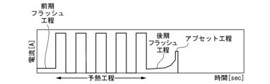
- current is applied to the rails for several to several tens of seconds, as shown in Figure 2A.
- the current waveform in the preheating process is sometimes called a hat-shaped waveform. Current may also be passed intermittently while the pair of rails are in contact.
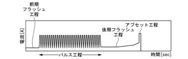
- the platen In the pulse process, on the other hand, the platen is moved while forward and backward pulses of several Hz are superimposed on the platen feed. At this time, the contact state of the pair of rails is only maintained for an extremely short time. In the pulse process, the platen is controlled so that the rails are separated as soon as they come into contact. However, as a result of the pair of rails being pressed together, the rails may not be separated quickly enough, and the pair of rails may appear to remain in contact. Flashing occurs when the pair of rails move forward and backward. The end faces of the rails are preheated by the flashing.
- the current waveform in the pulse process is a peak-shaped waveform as shown in Figure 2B.
- one of the two rails is advanced and retreated toward the other, but both rails may be moved toward and away from each other.
- advancing the rails is a concept that includes moving the two rails toward each other
- retreating is a concept that includes moving the two rails away from each other.
- the current value in the pulse process of the pulse flash method is smaller than the current value in the preheat process of the preheat flash method. Therefore, the integrated current value in the pulse process is smaller than the integrated current value in the preheat process of the preheat flash method.
- the integrated current value is the product of the average current value and the total current flow time in the preheat process or pulse process, and is an index of the heat input in the preheat process or pulse process.
- the total current flow time in the pulse process is the pulse process time, that is, the time from the start to the end of the pulse process.
- the average current value in the pulse process is the value obtained by dividing the time integral of the current value in the pulse process by the total current flow time.
- the total current flow time in the preheat process is the total current flow time in the preheat process. In the current waveform diagram of the preheat process shown in Figure 2A, the time when the current value is 0 is not included in the total current flow time.
- the average current value during the preheating process is the time integral of the current value divided by the total current flow time.
- Flash butt welded rails are required to meet the standards set by the standards in bending tests.
- AREMA American Railway Engineering and Track Maintenance Association
- the standard specifies that the deflection at break is 0.75 inches or more, and the bottom stress at break is 125,000 lb/ in2 or more.
- Flash butt welded rails welded with pulse flash FB welding must meet the standards for deflection and bottom stress at break, just like preheat flash FB welding.
- the inventors have confirmed that the proportion of joints obtained by pulse flash FB welding that do not satisfy the standards for bending tests is higher than that of FB welding by preheat flash welding. It is generally known that increasing the integrated current during welding is effective for increasing the amount of deflection and bottom stress at break in bending tests. However, compared to the preheat flash method, joints obtained by pulse flash flash butt welding have the problem that the amount of deflection and bottom stress at break in bending tests are less likely to satisfy the standards, even if the integrated current is increased.
- Flash butt welding of rails has mainly been carried out using the preheat flash method. Therefore, many documents have been published on welding methods using the preheat flash method. On the other hand, there are very few cases in which welding methods using the pulse flash method have been examined.
- Patent Document 1 discloses a welding method in which the forward and backward timing is determined by the current value and power value when welding large cross-sectional area high-temperature materials using a pulse flash method, with the aim of obtaining an arc with a large heat input effect.
- Patent Document 2 discloses a welding method in which the start temperature of the entire pulse process and the amount of erosion at the end are specified when welding rails using a pulse flash method, with the aim of increasing production capacity.
- Patent Document 3 discloses a welding method in which the heat input is specified when welding using a pulse flash method, with the aim of controlling the structure of R260 rail, a high-Mn rail.
- Non-Patent Document 1 discloses optimized welding conditions for rail pulse flashing at a frequency of 7 to 9 Hz.
- JP 2002-205175 A Japanese Unexamined Patent Publication No. 57-50285 Chinese Patent Publication No. 110616368
- the objective of the present invention is to (1) provide a manufacturing method for flash butt welded rails that can suppress fractures at low deflection and low bottom stress during bending tests of flash butt welded rails by using pulse flash flash welding, and (2) prevent the end faces of the rails from being crimped during the pulse process.
- the gist of the present invention is as follows:
- a manufacturing method of a flash butt welded rail includes an early flashing process in which a flash is generated between end faces of a pair of rails aligned along the longitudinal direction, thereby flattening the end faces; a pulse process in which the end faces of the pair of rails are repeatedly brought into contact with and separated from each other, thereby preheating the end faces; a late flashing process in which a flash is generated between the end faces of the pair of rails, thereby melting the end faces as a whole; and an upset process in which the end faces of the pair of rails are butted against each other and pressurized, thereby joining the rails; wherein a frequency in the pulse process is 1 to 10 Hz, a maximum current in the pulse process is 2.33 to 6.98 A/ mm2 , and an average current in the pulse process is 0.70 to 4.65 A/mm2.
- a final flashing velocity in the latter flashing step is 0.2 to 3.4 mm/sec
- the chemical components of the rail are, in mass %, C: 0.60 to 1.20%, Mn: 0.1 to 2.0%, Cr: 0.01 to 2.00%, Si: 0.10 to 2.00%, Al: 0.001 to 0.500%, P: 0.020% or less, S: 0.020% or less, N: 0.003 to 0.02 0%, V: 0-0.300%, Ti: 0-0.0500%, Nb: 0-0.050%, Cu: 0-1.000%, Ni: 0-1.00%, Ca: 0-0.0200%, REM: 0-0.0500%, and Mo: 0-0.500%, with the balance containing Fe and impurities.
- the upper limit of the integrated current, which is the product of the average current and the current flow time, in the unit of kA sec/mm 2 is (8 x the frequency - 480 x C content + 1400) / 8600
- the lower limit of the integrated current, in the unit of kA sec/mm 2 is (3.5 x the frequency - 180 x C content + 55 x Mn content + 45 x Cr content + 300) / 8600.
- the minimum current in the pulse process is preferably 0.12 A/ mm2 or more.
- the flash length in the latter flashing step is preferably set to 5 to 50 mm.
- the chemical components of the rail preferably contain, in mass%, one or more elements selected from the group consisting of V: 0.001-0.300%, Ti: 0.0008-0.0500%, Nb: 0.001-0.050%, Cu: 0.005-1.000%, Ni: 0.01-1.00%, Ca: 0.0005-0.0200%, REM: 0.0005-0.0500%, Al: 0.001-0.500%, and Mo: 0.002-0.500%.
- the manufacturing method of the flash butt welded rail according to the present invention (1) uses pulse flash flash welding to suppress breakage of the flash butt welded rail at low deflection and low bottom stress during bending tests, and (2) provides a manufacturing method of the flash butt welded rail that can prevent the end faces of the rail from being crimped during the pulse process.
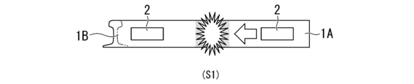
- FIG. FIG. 2 is a schematic diagram of a pulse process.
- FIG. 2 is a schematic diagram of a later flash process.
- FIG. FIG. 1 is a comparison diagram of current value changes in flash butt welding using the preheat flash method.
- FIG. 11 is a comparison diagram of current value changes in pulse flash type flash butt welding.
- 1 is a graph showing the relationship between the maximum flat spot length and the bottom stress at the time of bending fracture.
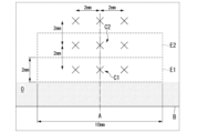
- FIG. 13 is a diagram showing the locations at which the end surface temperatures are measured and the evaluation units for the low temperature portions.
- FIG. 4B is an enlarged view of the rectangular area enclosed by the dashed line in FIG. 4A.
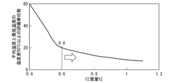
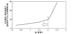
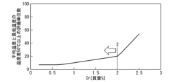
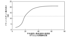
- 13 is a graph showing the relationship between C and the number of evaluation units in which the temperature difference between the average temperature and the minimum temperature of the end face immediately after the pulse process is 50° C. or more. 13 is a graph showing the relationship between Mn and the number of evaluation units in which the temperature difference between the average temperature and the minimum temperature of the end face immediately after the pulse process is 50° C. or more. 13 is a graph showing the relationship between Cr and the number of evaluation units in which the temperature difference between the average temperature and the minimum temperature of the end face immediately after the pulse process is 50° C. or more. 13 is a graph showing the relationship between the number of evaluation units in which the temperature difference between the average temperature and the minimum temperature of the end face immediately after the pulse process is 50° C.
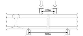
- FIG. 1 is a schematic diagram showing a bending test method.
- the chemical components of the rails 1A and 1B, the frequency, maximum current, average current, and integrated current in the pulse process S2, and the final flashing velocity in the latter flashing process S3 are set within the optimum ranges. That is, the manufacturing method of the flash butt welded rail according to the present embodiment, as shown in Figs.
- the welding conditions include planned values that are determined before welding begins, and actual values that are measured during welding.
- the above-mentioned welding conditions are based on the actual values.
- the "maximum pulse time ratio,” which will be described later, is an indicator that shows the deviation between the planned value and the actual value.
- FIGS. 1A to 1D also illustrate an example of a welding method in which electrodes are pressed against the rail column.
- the electrodes are arranged so as to sandwich the rail column from both sides.
- FIG. 1A to 1D only the electrodes arranged on the front side of the column are shown, and the electrodes arranged on the rear side of the column are omitted.
- the locations where the electrodes are installed are not particularly limited. Flash butt welding may be performed by pressing the electrodes against the head surface and foot sole of the rail.
- the manufacturing method according to this embodiment flash butt welding can be continued without crimping of the end faces during the pulse process. Furthermore, in bending tests of the joint obtained by the manufacturing method according to this embodiment, i.e., the flash butt welded rail, the weld does not break with low deflection and low bottom stress. Therefore, the bending performance of the flash butt welded rail obtained by the manufacturing method according to this embodiment can satisfy the rail welding standards.
- Flash butt welded rail A rail obtained by welding two or more rails together by flash butt welding.
- a flash butt welded rail has a base metal part and a weld part, and the base metal part has the same chemical composition and structure as the rail before welding.
- Crimping This refers to the state in which, during rail advancement and retreat control at a predetermined frequency, the end faces (welded surfaces) of two butted rails stick together and cannot be separated, or the end faces become difficult to separate, causing the time required for the rails to retreat to become longer than the predetermined time.
- Oxide defect In flash butt welding, which is atmospheric welding, this refers to oxides that are generated in the later flash process and remain in the weld joint without being expelled in the upset process. This often becomes the starting point of fractures in bending tests and fatigue tests of weld joints.
- Accumulated current The product of the average current and the total current flow time in the pulse process of flash butt welding using the pulse flash method, or in the preheat process of flash butt welding using the preheat flash method.
- the accumulated current is an indicator of the amount of heat input in the pulse process or preheat process.
- Planned Pulse Time This refers to the planned value of the time required to perform one pulse, determined before welding.
- Actual pulse time This refers to the actual time required for one pulse, measured from the actual current waveform during welding. In the pulse process, a pair of rails may be pressed together and may not be separated quickly. Therefore, the planned pulse time and the actual pulse time do not necessarily match.
- Maximum Actual Pulse Time In a pulse process having multiple pulses, this is the maximum value of the actual pulse time.
- Maximum pulse time ratio The maximum actual pulse time divided by the planned pulse time, and is an index showing the deviation between the planned and actual values. A maximum pulse time ratio of 100% indicates that the rail has advanced and retreated in the specified time.
- pulse flash flash butt welding has an early flash process S1, a pulse process S2, a late flash process S3, and an upset process S4.
- a gap is provided between the end faces of a pair of rails aligned in the longitudinal direction, and the two rails are moved toward each other while a voltage is applied, thereby causing a flash between the end faces.
- the end faces are usually not flat.
- a short-circuit current flows locally between the end faces, causing rapid heating due to resistance heating and leading to melting.
- the end faces are then bridged by molten metal. An arc is generated at this bridge. The arc scatters some of the molten metal and heats the end faces with radiant heat. In the pre-flash process, these phenomena are continuously repeated. This causes the end faces of the rails to be flattened.
- the forward movement speed of the rail at this time is called the flash speed, and the amount of movement is called the flash length.
- the flash speed When only one of the rails is moved, the amount of movement of this rail is considered to be the flash length.
- the total amount of movement of both rails is considered to be the flash length.
- the pulse process S2 the later flash process S3, and the upset process S4
- the amount of movement of the rails is also determined by the above-mentioned method.
- moving the end faces of the rails closer to each other will be referred to as "forward movement”
- moving the end faces of the rails away from each other will be referred to as "backward movement”.
- the rail is repeatedly advanced and retreated at a frequency of several Hz. This causes the end faces of a pair of rails to repeatedly come into contact with each other and separate from each other. This preheats the end faces.
- the contact area of the end faces is at a maximum, and when the rail is retreated, the contact area of the end faces is zero or a small value close to this.
- the current increases in proportion to the contact area of the end faces. Therefore, in the pulse process, the current increases and decreases repeatedly. When the two end faces are completely separated, the current becomes zero.
- a flash is generated between the end faces of a pair of rails.
- the principle of the later flashing process is the same as that of the earlier flashing process.
- the speed at which the rail is advanced in the later flashing process i.e., the later flashing speed
- the later flashing speed is generally faster than the flashing speed in the earlier flashing process, i.e., the earlier flashing speed.
- the later flashing length is generally longer than that in the earlier flashing process.
- the earlier flashing process moves to the next pulse process at the stage where the end faces are flattened, whereas the later flashing process moves to the next upset process at the stage where the end faces are entirely melted.
- the manufacturing method according to this embodiment may further include a process for removing burrs 3.
- rail materials are generally eutectoid or hypereutectoid rail steels containing 0.60 to 0.86 mass% C. Recently, rail steels with higher C content have become more common in order to further improve the wear resistance of flash-butt welded rails.
- the cross-sectional size of flash-butt welded rails is selected according to the weight of freight cars on the line where the rails are used. In other words, rails with high rigidity and large cross-sectional size are used in sections where heavy freight cars pass.
- the fracture surface formed by performing a bending test on a flash butt welded rail has one or more areas (called "flat spots") with no surface irregularities, which are clearly different from brittle fracture surfaces and can be visually confirmed.
- the flat spots are analyzed, they are found to contain aggregates of oxides of Mn, Cr, etc. Therefore, the flat spots are a type of oxide defect. It is known that flat spots cause a decrease in the deflection amount and bottom stress in bending tests.
- the deflection amount and bottom stress at the time of fracture in the bending test may not satisfy the standard because there are parts on the end surface where the temperature is difficult to rise sufficiently in the pulse process.
- the chemical composition of the rail contains a lot of alloy components that are prone to oxide formation, oxides are likely to form on the end surface in the pulse process.
- the current is extremely difficult to flow and the temperature is difficult to rise.
- the part where the oxide is formed on the end surface cannot be sufficiently preheated even by the pulse process. Therefore, the temperature of the part where the oxide is formed in the pulse process does not rise sufficiently even in the later flash process.
- the oxide formed in the later flash process is difficult to discharge in the upset process.
- the part where the oxide is formed in the pulse process is likely to become an oxide defect (flat spot).
- the inventors believe that in the bending test of flash butt welded rails, fracture occurs with low deflection and low bottom stress. The inventors believe that most of the oxides formed in the pulse process are scattered together with the molten steel in the subsequent later flash process. Therefore, it is presumed that the oxides that form the flat spots are not oxides formed in the pulse process, but oxides formed in the later flash process.
- the heat input influence factors include integrated current, maximum current, average current, frequency, etc.
- Pulse flash flash welding was carried out under the basic conditions of an integrated current of 500 kA ⁇ sec (0.06 kA ⁇ sec/ mm2 ), a maximum current of 30000 A (3.49 A/ mm2 ), an average current of 18000 A (2.09 A/ mm2 ), and a frequency of 5 Hz.
- the number of low temperature parts on the end face after the pulse process was used as an index.
- the number of low temperature parts on the end face after the pulse process was measured by pulling away the end face immediately after the pulse process. It is also considered that the oxides generated on the end face during the pulse process are discharged to the outside together with the scattering of molten steel in the later flash process.
- thermoviewer a thermometer that measures the temperature distribution on an object surface without contact
- the number of detection pixels required for a thermoviewer is 320 or more in the horizontal direction and 240 or more in the vertical direction.
- the measurement target is the range below the neutral line in the height direction of the rail. In bending tests of welded rails, tensile stress acts below the neutral line, so it was thought necessary to evaluate the oxides present in that range by measuring the temperature in that range.
- the outer periphery of the end face and the inner 2 mm area are not subject to the evaluation of low temperature areas. This is because the outer periphery of the end face and the inner 2 mm area are cooled by the surrounding air, so the temperature is low regardless of whether oxides are generated or not.
- the molten metal on the outer periphery of the end face and its vicinity is easily discharged to the outside during the upset process, it was thought that even if oxides were generated in this area during the later flash process, they would be discharged and rendered harmless during the upset process.
- thermoviewer Temperature measurements were performed by pulling away the end face immediately after the pulse process was completed, and measuring the temperature of the end face below the neutral line in the height direction with a thermoviewer. At this time, the distance between the thermoviewer and the end face was adjusted so that the length of the area corresponding to one pixel on the end face was 0.5 mm or less in both the horizontal and vertical directions. Specifically, the distance was adjusted so that the width of the horizontal field of view of the thermoviewer matched the width of the foot of the rail. It is preferable that the bottom of the rail and the bottom edge of the thermoviewer image are parallel.
- FIG. 4A is a schematic diagram of the rail end face
- Figure 4B is a schematic diagram of the range of the rail end face below the neutral line in the height direction.
- the rectangular area surrounded by the dashed line in Figure 4A is Figure 4B.
- the dashed line with the symbol A is the width center of the rail end face
- the solid line with the symbol B is the lower end of the rail end face, that is, the bottom surface of the rail
- the area with the symbol O is the measurement exclusion area.
- the x mark with the symbol C1 is the center of the first evaluation unit
- the rectangular area with a width of 10 mm and a height of 2 mm surrounded by the dashed line with the symbol E1 is the first evaluation unit.
- Symbols E2 and C2 are the second evaluation unit and its center.
- the shape of the evaluation unit was a rectangle measuring 10 mm in the width direction of the end face of the rail and 2 mm in the height direction.
- the position of the evaluation units was as follows. First, the center C1 of the first evaluation unit E1 was placed on the widthwise center A of the end face of the rail and 3 mm above the rail foot underside B. Next, using the first center C1 as a reference, each point with a pitch of 2 mm in the width direction and a pitch of 2 mm in the height direction was set as the center position of the second and subsequent evaluation units.
- the x marks other than C1 shown in FIG. 4B are the center positions of the second and subsequent evaluation units.
- the second evaluation unit E2 is also shown in FIG. 4B. However, the third and subsequent evaluation units are omitted. Note that each evaluation unit will overlap with each other at the widthwise end. Also, only nine centers of the evaluation positions are shown in FIG. 4B, and the tenth and subsequent evaluation positions are omitted.
- the temperature measurement results obtained using the thermoviewer were cut out for each evaluation unit.
- the temperature difference between the average temperature and the minimum temperature within each evaluation unit was then calculated. However, if the range of an evaluation unit includes conditions that are excluded from the above measurement targets (the outer periphery of the rail and 2 mm inside), that evaluation unit is excluded from the evaluation targets.
- the C content of the rail is in the range of 0.6 mass% or more, the number of evaluation units with a temperature difference of 50°C or more increases with a decrease in the C content, but the rate of increase is small. For this reason, the C content of the rail is set to 0.6 mass% or more. In order to further improve the bending performance, the C content of the rail is preferably set to 0.7 mass% or more.
- the inventors have clarified that when the C content of the rail falls below 0.6 mass%, the number of evaluation units with a temperature difference of 50°C or more increases significantly. It is presumed that the reason for the increase in the number of evaluation units with a temperature difference of 50°C or more when the C content of the rail falls below 0.6 mass% is that C is a highly reducing element, and as the C content decreases, oxides are more likely to form, increasing the number of oxides formed. Furthermore, as mentioned above, since oxides do not allow electrical current to flow easily, a temperature difference is likely to occur between areas where oxides do not form and areas where oxides have formed, and it is believed that this is why the number of evaluation units with large temperature differences increased. It is believed that this tendency became more noticeable when the C content was less than 0.6%.
- the Mn content of the rail is in the range of 2.0 mass% or less, the number of evaluation units with a temperature difference of 50°C or more increases with an increase in the Mn content, but the rate of increase is small.
- the inventors have clarified that when the Mn content exceeds 2.0 mass%, the number of evaluation units with a temperature difference of 50°C or more increases significantly. For this reason, the Mn content of the rail is set to 2.0 mass% or less. In order to further improve bending performance, the Mn content of the rail is preferably set to 1.5 mass% or less.
- the Cr content of the rail is in the range of 2.0 mass% or less, the number of evaluation units with a temperature difference of 50°C or more increases with an increase in the Cr content, but the rate of increase is small.
- the inventors have clarified that when the Cr content exceeds 2.0 mass%, the number of evaluation units with a temperature difference of 50°C or more increases significantly. For this reason, the Cr content of the rail is set to 2.0 mass% or less.
- the Cr content of the rail is preferably set to 1.3 mass% or less.
- the maximum flat spot length would be 12 mm when there were 20 evaluation units with a temperature difference of 50°C or more between the average temperature and the minimum temperature. Therefore, to satisfy the standards for bending tests, it is necessary to select the C, Mn, and Cr contents of the rail so that the number of evaluation units with a temperature difference of 50°C or more between the average temperature and the minimum temperature is 20 or less, as shown in Figures 5 to 7.
- the C content should be in the range of 0.6 mass% or more, and the Mn and Cr content should be in the range of 2.0 mass% or less.
- the C content should preferably be in the range of 0.7 mass% or more, the Mn content should be 1.5 mass% or less, and the Cr content should be 1.3 mass% or less.
- the frequency range is set to 10 Hz or less. In order to further improve bending performance, the frequency range is preferably set to 8 Hz or less, 7 Hz or less, or 6 Hz or less.
- the cross-sectional area of the rail is 8600 mm 2
- the integrated current is 500 kA ⁇ sec (0.06 kA ⁇ sec/mm 2 )
- the maximum current is 30000 A (3.49 A/mm 2 )
- the average current is 18000 A (2.09 A/mm 2 )
- the C content is 0.9 mass%
- the Mn content is 1.0 mass%
- the Cr content is 0.5 mass%.
- C%, Mn%, and Cr% are the C content, Mn content, and Cr content of the rail in unit mass%, respectively.
- the C content is 0.6 mass% or more
- the Mn content is 2.0 mass% or less
- the Cr content is 2.0 mass% or less
- the frequency is 1 Hz or more.
- the reason why the maximum flat spot length increases with a decrease in maximum current is believed to be that, as mentioned above, the integrated current in the pulse process is small, so the temperature of the end face does not rise sufficiently in the later flash process, and the oxides generated in the later flash process are difficult to remove in the upset process.
- the cross-sectional area of the rail at this time is 8,600 mm2
- the integrated current is 500 kA ⁇ sec (0.06 kA ⁇ sec/ mm2 )
- the average current is 18,000 A (2.09 A/ mm2 )
- the C content is 0.9 mass%
- the Mn content is 1.0 mass%
- the Cr content is 0.5 mass%.
- the reason why the maximum flat spot length increases with the decrease in the average current in the pulse process is believed to be that, as mentioned above, the integrated current in the pulse process is small, so the temperature of the end face does not rise sufficiently in the later flash process, and the oxides generated in the later flash process are difficult to remove in the upset process.
- the cross-sectional area of the rail at this time is 8,600 mm2
- the integrated current is 500 kA ⁇ sec (0.06 kA ⁇ sec/ mm2 )
- the maximum current is 30,000 A (3.49 A/ mm2 )
- C is 0.9 mass%
- Mn is 1.0 mass%
- Cr is 0.5 mass%.
- the inventors have obtained the following findings regarding the occurrence of compression bonding in a pulse process.
- the integrated current maximum current, average current
- the amount of heat input to the end face increases.
- crimping is likely to occur.
- the frequency is low in the pulse process, the time during which the temperature remains high during one forward movement will be longer, resulting in a larger temperature rise at the end face, making crimping more likely to occur.
- the rail in the pulse process of flash butt welding using the pulse flash method, the rail repeatedly advances and retreats, and even when the rail advances to its maximum extent, the end faces do not all come into contact, but only partially. This has a significant effect on the formation of crimping.
- the Joule heat in that part increases, and the temperature of that part and its surrounding area increases. As a result, crimping is likely to occur.
- the end surface in the pulse process is affected by the scattering of molten metal before the pulse process, and is not completely flat, but has numerous irregularities.
- the convex parts come into contact first, and are heated by Joule heating to a high temperature.
- the temperature of the end surface is uneven, and there are areas of the end surface that are partially melted.
- the rail retreats the melted parts solidify as the temperature drops.
- alloy elements are expelled from the solid phase to the liquid phase, and an area where the alloy elements are concentrated occurs.
- C has a small equilibrium distribution coefficient of 0.2.
- the electrical resistivity of graphite at high temperatures is about 8.4 ⁇ m (Nishimoto et al., Toyo Tanso Co., Ltd., "Device for measuring high-temperature resistivity change rate of graphite material by direct current application", 2015).
- the electrical resistivity of rail steel at high temperatures is about 2.1 ⁇ m. The inventors have found that this is about 1/4 of the electrical resistivity of graphite.
- the electrical resistance of graphite at high temperatures is extremely high compared to the electrical resistance of rail steel. For this reason, the amount of Joule heat generated in the graphite part is high compared to rail steel, and as a result of the high temperature of the graphite part and its vicinity, it is believed that crimping is more likely to occur.
- the end faces melt, causing alloy elements to be discharged to the end faces, which can increase electrical resistance.
- the entire end faces come into contact and melt. Therefore, the discharge of alloy elements during solidification causes enrichment across the entire end faces.
- the enriched area is expelled to the outside at the same time as the molten steel is scattered. Therefore, it is estimated that the effect of enrichment is small in flash butt welding using the preheating flash method. Therefore, the inventors considered that crimping is less likely to occur in the preheating process using the preheating flash method compared to the pulse process using the pulse flash method.
- the maximum pulse time is the value obtained by dividing the maximum actual pulse time, which is the maximum value of the actual pulse time, by the planned pulse time, which is the planned value of the pulse time determined before welding.
- the maximum pulse time is an index showing the deviation between the planned value and the actual value.
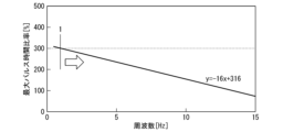
- the maximum pulse time ratio exceeds 300%, the ratio at which retraction is not possible increases significantly. Therefore, the maximum pulse time ratio must be kept below 300%. In order to suppress crimping, it is important to keep the maximum pulse time ratio below 300% by optimizing the pulse conditions and component conditions.
- the reason why the maximum pulse time ratio increases when the C content is high is considered to be as follows.
- the end face may become partially hot and melt.
- the temperature of the end face decreases and the molten part solidifies.
- C is expelled from the solid phase to the liquid phase, a C-enriched area is partially generated, and C precipitates as graphite.
- the electrical resistance of graphite is high compared to the rail steel material. Therefore, the Joule heat generation in the graphite precipitation area, i.e., the graphite part, is large compared to its surroundings. The inventors believe that the graphite part and its vicinity become hot, so that the end face is easily stuck.
- the cross-sectional area of the rail was 8,600 mm2
- the integrated current was 500 kA ⁇ sec (0.06 kA ⁇ sec/ mm2 )
- the maximum current was 30,000 A (3.49 A/ mm2 )
- the average current was 18,000 A (2.09 A/ mm2 )
- the frequency was 5 Hz
- the Mn content was 1.0 mass%
- the Cr content was 0.5 mass%.
- the reason why the maximum pulse time ratio increases with decreasing frequency is considered to be that, as mentioned above, when the frequency is low, the total time of forward and backward movement of one pulse is long, the amount of heat input to the end face is large, and the temperature of the end face is high, which makes the end face more likely to stick.
- the cross-sectional area of the rail at this time is 8600 mm2
- the integrated current is 500 kA ⁇ sec (0.06 kA ⁇ sec/ mm2 )
- the maximum current is 30,000 A (3.49 A/ mm2 )
- the average current is 18,000 A (2.09 A/ mm2 )
- the C content is 0.9 mass%
- the Mn content is 1.0 mass%
- the Cr content is 0.5 mass%.
- the cross-sectional area of the rail is 8600 mm 2
- the integrated current is 500 kA ⁇ sec (0.06 kA ⁇ sec/mm 2 )
- the average current is 18,000 A (2.09 A/mm 2 )
- the C content is 0.9 mass%
- the Mn content is 1.0 mass%
- the Cr content is 0.5 mass%
- the frequency is 5 Hz.
- the cross-sectional area of the rail was 8,600 mm2
- the integrated current was 500 kA ⁇ sec (0.06 kA ⁇ sec/ mm2 )
- the maximum current was 30,000 A (3.49 A/ mm2 )
- the C content was 0.9 mass%
- the Mn content was 1.0 mass%
- the Cr content was 0.5 mass%
- the frequency was 5 Hz.
- the lower limit of the frequency in the pulse process is 1 Hz.
- the frequency range is preferably 2 Hz or more, 3 Hz or more, or 4 Hz or more.
- the upper limit of the frequency in the pulse process is 10 Hz. From the viewpoint of further suppressing oxides, it is preferable that the upper limit of the frequency in the pulse process is 9 Hz or less, 8 Hz or less, or 6 Hz or less. The most preferable range of the frequency is 3 Hz or more and 6 Hz or less.
- the lower limit of the maximum current in the pulse process is 2.33 A/ mm2 .
- the maximum current in the pulse process is preferably 2.50 A/ mm2 or more, 2.91 A/ mm2 or more, or 3.20 A/ mm2 .
- the upper limit of the maximum current in the pulse process is 6.98 A/ mm2 .
- the maximum current is preferably in the range of 6.00 A/ mm2 or less, 5.23 A/ mm2 or less, or 4.80 A/ mm2 or less.
- the most preferable range of the maximum current in the pulse process is 2.91 A/ mm2 or more and 5.23 A/ mm2 or less.
- the lower limit of the average current in the pulse process is 0.70 A/ mm2 .
- the range of the average current in the pulse process is 1.00 A/ mm2 or more, 1.74 A/ mm2 or more, or 2.00 A/ mm2 or more.
- the upper limit of the average current in the pulse process is 4.65 A/ mm2 .
- the range of the average current is preferably 4.00 A/ mm2 or less, 3.26 A/ mm2 or less, or 2.80 A/ mm2 or less.
- the most preferable range of the average current in the pulse process is 1.74 A/ mm2 or more and 3.26 A/ mm2 or less.
- the final flash velocity in the later flash process means the average value of the flash velocity in the last 5 seconds of the later flash process. That is, the final flash velocity in the later flash process is the value obtained by dividing the amount of rail movement in the last 5 seconds of the later flash process by 5 seconds.
- the final flash velocity in the later flash process means the average value of the flash velocity from the start to the end of the later flash process, that is, the value obtained by dividing the later flash length, which is the amount of rail movement in the later flash process, by the time of the later flash process.
- the later flashing velocity The faster the flashing velocity in the later flashing process, i.e., the later flashing velocity, the higher the current and the higher the temperature of the end surface immediately before the upset process. As a result, the oxides generated in the later flashing process are more easily expelled from the weld in the upset process. However, even if the later flashing velocity is increased only immediately before the upset process, the effect of increasing the temperature of the end surface is limited. Therefore, in the later flashing process, the lower limit of the final flashing velocity is set to 0.2 mm/sec.
- the final flashing velocity is preferably 0.5 mm/sec or more, 0.8 mm/sec or more, or 1.0 mm/sec.
- the upper limit of the final flash velocity is set to 3.4 mm/sec.
- the final flash velocity is preferably 3.0 mm/sec or less, 2.5 mm/sec or less, or 2.0 mm/sec or less.
- the most preferred range of the final flash velocity is 0.6 mm/sec or more and 2.8 mm/sec or less.
- the lower limit of the C content is set to 0.60 mass %.
- the C content is preferably 0.65 mass % or more, and more preferably 0.70 mass % or more.
- the upper limit of the C content is set to 1.20 mass%.
- the C content is preferably 1.10 mass%.
- the C content is preferably 0.70 mass% or more and 1.10 mass% or less.
- the upper limit of the Mn content is set to 2.00 mass %, and preferably 1.80 mass % or less, and 1.50 mass % or less.
- Mn is an element that exerts an effect of increasing hardness by improving hardenability. If the Mn content is insufficient, this effect cannot be obtained. Therefore, the lower limit of the Mn content is The value is 0.10 mass%.
- the Mn content is preferably 0.20 mass% or more, 0.50 mass% or more, or 0.80 mass% or more. The most preferable range of the Mn content is 0.20 mass% or more. % or more and 1.80 mass % or less.
- the upper limit of the Cr content is set to 2.00 mass %, and preferably, the Cr content is set to 1.80 mass % or less, and 1.50 mass % or less.
- the lower limit of the Cr content is set to 0.01 mass%.
- the Cr content is preferably 0.20 mass% or more, 0.50 mass% or more, or 0.80 mass% or more.
- the most preferable range of the Cr content is 0.20 mass% or more and 1.30 mass% or less.
- the upper limit of the integrated current is (8 x frequency - 480 x C mass % + 1400) / 8600 in units of kA sec/ mm2 > From the viewpoint of preventing crimping described in the above item l, the upper limit of the integrated current is defined as a function of the frequency in the pulse process and the C amount of the rail.
- the lower limit of the integrated current is (3.5 x frequency - 180 x C% + 55 x Mn% + 45 x Cr% + 300) / 8600 in units of kA sec/ mm2 >
- the lower limit of the integrated current is defined as a function of the frequency in the pulse process and the C content, Mn content, and Cr content of the rail.
- the minimum current in the pulse process is 0.12 A/ mm2 or more>
- the current value is 0 A/ mm2 . Therefore, the minimum value of the current in the pulse process is 0 A.
- the current value may not drop to 0 A/ mm2 .
- the phenomenon in which the end faces stick together and cannot be separated i.e., crimping
- the crimped end faces must be cut off and the flash butt welding must be started over from the beginning.
- it is not necessary to completely separate the end faces for each pulse in the pulse process Rather, it is believed that if the rails that are butted together do not completely separate when the rails are retracted during the pulse process, oxides are less likely to form on the end faces. Also, as long as the above-mentioned conditions are met, there will be no increase in the maximum pulse time ratio or crimping of the end faces even if the rails that are butted together do not completely separate when the rails are retracted.
- the minimum current may be set to 0.12 A/ mm2 as an index for preventing the end faces from being completely separated. By doing so, oxides are less likely to be generated on the end faces, and further improvement in bending performance is expected. More preferable ranges of the minimum current in the pulse process are 0.1812 A/ mm2 or more, 0.23 A/ mm2 or more, or 0.25 A/ mm2 or more.
- the flash length in the latter flash step is 5 to 50 mm>
- the flash length in the latter flashing step i.e., the latter flashing length, is the amount of movement of the rail from the start to the end of the latter flashing step.
- the latter flashing velocity in the latter flashing step.
- the lower limit of the latter flashing length is preferably 5 mm. It is more preferable to set the latter flashing length to 6 mm or more, 8 mm or more, or 10 mm or more.
- shortening the late flash length eliminates the need to pull the rail to fill gaps that occur in the longitudinal direction or to prepare another rail. Therefore, suppressing the late flash length leads to improved rail construction workability. Therefore, it is preferable to set the upper limit of the late flash length to 50 mm. It is even more preferable to set the late flash length to 45 mm or less, 40 mm or less, or 30 mm or less. An even more preferable range for the late flash length is 10 mm or more and 40 mm or less.
- Silicon is an element that strengthens the ferrite phase in the pearlite structure by solid solution strengthening, thereby contributing to increasing the strength of the base material.
- the rail should contain 0.10% to 2.00% silicon.
- the Si content is preferably 1.80 mass% or less, 1.50 mass% or less, or 1.20 mass% or less. If the Si content is less than 0.10%, the effect cannot be obtained, If the Si content exceeds 2.00%, the material becomes easily embrittled.
- the Si content is preferably 0.20 mass% or more, 0.50 mass% or more, or 0.80 mass% or more. A more preferable range of the Si content is 0. .20% or more and 1.50% or less
- Al 0.001 to 0.500% by mass>
- Al is contained in rails as a deoxidizing element. Furthermore, Al is an element that reduces the difference in hardness of pearlite structures and improves the fatigue strength of the rail web portion. Therefore, the Al content is set to 0.001% or more.
- the Al content is preferably 0.100 mass % or more, 0.120 mass % or more, or 0.150 mass % or more. On the other hand, the generation of coarse oxides and coarse martensite is suppressed, and fatigue strength is improved. From the viewpoint of further improving the above, the Al content is set to 0.500% or less.
- the Al content is preferably 0.450% by mass or less, 0.400% by mass or less, or 0.300% by mass or less. A more preferable range is , Al is 0.005% or more and 0.100% or less.
- P and S are impurities in steel. If there is a large amount of P and S, the toughness of the steel decreases, and the fatigue strength of the flash butt welded rail decreases. Therefore, in order to increase the fatigue strength of the welded rail, P is set to 0.
- the preferred range of P is 0.010% or more and 0.018% or less
- the preferred range of S is 0.008% or more and 0.018% or less.
- the lower limits of the P content and the S content are not particularly limited and may be 0%.
- the P content and the S content are each set to 0.001 mass% or more, and 0.001 mass% or less. It may be 0.010 mass % or more, or 0.010 mass % or more.
- N is an element that makes the hardness of the pearlite structure uniform and improves the fatigue strength of the rail web. Therefore, N may be contained in the rail in an amount of 0.003% or more and 0.020% or less, if necessary. If the N content exceeds 0.020%, coarse nitrides may form, which may reduce the fatigue strength. Therefore, the preferred range of N content is 0.008% or more and 0.018% or less.
- V 0.001 to 0.300 mass%>
- Ti 0.0008 to 0.0500 mass%>
- Nb 0.001 to 0.050 mass%>
- V, Ti, and Nb are not essential for the rail used as the welding base metal. Therefore, the V amount, Ti amount, and Nb amount may be 0%.
- V, Ti, and Nb are elements that increase the hardness of the steel by precipitation strengthening and improve the fatigue strength of the flash butt welded rail. Therefore, V may be contained in the rail at 0.001% to 0.300%, Ti at 0.0008% to 0.0500%, and Nb at 0.001% to 0.050% as necessary.
- V is less than 0.001%, Ti is less than 0.0008%, and Nb is less than 0.001%, the effect of increasing the hardness and improving the fatigue strength cannot be obtained.
- V is 0.300% or less, Ti is 0.0500% or less, and Nb is 0.050% or less. More preferable ranges are 0.005% or more and 0.200% or less for V, 0.0030% or more and 0.0400% or less for Ti, and 0.003% or more and 0.030% or less for Nb.
- ⁇ Cu preferably 0.005 to 1.000 mass%>
- ⁇ Ni preferably 0.01 to 1.00 mass%>
- Cu and Ni are not essential for the rail of the manufacturing method according to this embodiment. Therefore, the Cu amount and Ni amount may be 0%.
- Cu and Ni are elements that increase the hardness of steel by solid solution strengthening and improve the fatigue strength of the flash butt welded rail. Therefore, Cu may be contained in the rail at 0.005% to 1.000% and Ni at 0.01% to 1.00% as necessary. If Cu is less than 0.005% and Ni is less than 0.01%, the effect of increasing hardness and improving fatigue strength cannot be obtained.
- Cu is 1.000% or less and Ni is 1.00% or less. More preferable ranges are Cu 0.010% to 0.600% and Ni 0.02% to 0.60%.
- Ca 0.0005 to 0.0200 mass%>
- REM 0.0005 to 0.0500 mass%>
- Ca and REM are not essential for the rail of the manufacturing method according to this embodiment. Therefore, the Ca content and the REM content may be 0%.
- Ca has a strong bond with S and forms sulfides. These sulfides finely disperse MnS, thereby further improving the fatigue strength of the rail.
- REM acts as a nucleus for generating oxides and MnS. These finely disperse MnS, thereby further improving the fatigue strength of the rail.
- Ca may be contained in the rail in an amount of 0.0005% or more and 0.0200% or less, and REM may be contained in an amount of 0.0005% or more and 0.0500% or less. If Ca is less than 0.0005% and REM is less than 0.0005%, the effect of improving fatigue strength cannot be obtained. In order to suppress the generation of coarse oxides and coarse oxysulfides and further improve fatigue strength, it is preferable that Ca is 0.0200% or less and REM is 0.0500% or less. More preferably, Ca is 0.0008% or more and 0.0180% or less and REM is 0.0010% or more and 0.0450% or less.
- REM is a rare earth element such as Ce, La, Pr or Nd. The upper and lower limits of the REM content limit the sum of the contents of all these REM elements.
- Mo: 0.002 to 0.500 mass%> Mo is not essential for the rail of the manufacturing method according to this embodiment. Therefore, the amount of Mo may be 0%.
- Mo is an element that hardens the steel and improves the fatigue strength of the flash butt welded rail by refining the lamellar spacing (spacing between the ferrite phase and the cementite phase) of the pearlite structure. Therefore, Mo may be contained in an amount of 0.002% or more and 0.500% or less as necessary. If Mo is less than 0.002%, the effect of increasing hardness and improving fatigue strength cannot be obtained.
- Mo is preferably 0.500% or less. A more preferable range of Mo is 0.010% or more and 0.300% or less.
- the remainder of the chemical composition of the rail includes iron and impurities.
- the rail may contain alloy elements other than those exemplified above, so long as the contents of C, Mn, and Cr, which may adversely affect the bending test results and welding workability of flash butt welded rails, are within the above-mentioned ranges. It is also acceptable for the chemical compositions of the two rails to be welded to differ slightly. In this case, it is sufficient that the average value of the chemical compositions of the two rails meets the above-mentioned conditions.
- impurities refers to chemical components of rails that are mixed in, for example, during the industrial production of steel materials, from raw materials such as ores or scrap, or from various factors in the manufacturing process, and are acceptable to the extent that they do not adversely affect the flash butt welded rail obtained by the manufacturing method according to this embodiment.
- ⁇ Other conditions> In the manufacturing method of the flash butt welded rail according to the present embodiment, various welding conditions can be adopted as long as the above-mentioned conditions are satisfied.
- normal conditions that can flatten the end surface of the rail to a degree that can be used in the pulse step can be appropriately adopted.
- normal conditions that can form a normal weld can also be appropriately adopted.
- the pressure in the upset step is not particularly limited, but from the viewpoint of further improving the oxide discharge ability, it is preferable to set it to 55 MPa or more, 58 MPa or more, or 60 MPa or more.
- the pressure in the upset step is 120 MPa or less, 100 MPa or less, or 82 MPa or less.
- normal conditions can also be appropriately adopted for welding conditions not described above.
- the manufacturing method of the flash butt welded rail may include additional steps such as a step of removing burrs and a step of performing post-heat treatment on the weld.
- the bending test is performed in accordance with the AREMA-sec. 2.3.3.6 standard of the American railway Engineering and Maintenance-of-Way Association. That is, as shown in FIG. 17, the welded rail is supported with a support distance of 1200 mm centered on the welded part. Then, a load is applied to the welded rail from above the welded rail at intervals of 300 mm centered on the welded part. The load is increased until the welded rail breaks. Then, the longitudinal stress (bottom stress) of the bottom of the welded rail at the time of break is measured based on the deflection of the welded rail at the time of break and the load at the time of break.
- the deflection at the time of break of 0.75 inches or more and the bottom stress of 125 kbp/inch 2 or more are considered to be acceptable.
- the flash-butt welded rail obtained by the manufacturing method according to the present embodiment is able to meet the above-mentioned pass/fail criteria since the formation of flat spots in the welds is extremely effectively suppressed.
- the conditions in the example are merely one example of conditions adopted to confirm the feasibility and effect of the present invention.
- the present invention is not limited to this one example of conditions.
- Various conditions may be adopted in the present invention as long as they do not deviate from the gist of the present invention and the object of the present invention is achieved.
- Two rails having different chemical compositions as shown in Tables 1A, 1B, 2A, and 2B were flash butt welded by pulse flash welding.
- the flash butt welding conditions were as shown in Tables 3A, 3B, 4A, and 4B.
- the cross-sectional area of the rail was 8600 mm2 .
- the symbol "-" indicates that the element with that symbol is not intentionally added to the rail.
- the “maximum current” in Tables 3A and 3B is the maximum value of the current passed through the rail in the pulse process.
- the “maximum current per cross-sectional area” is the value obtained by dividing the “maximum current” by the cross-sectional area of the rail, 8600 mm2.
- the “average current” in Tables 3A and 3B is the average value of the current passed through the rail in the pulse process.
- the “average current per cross-sectional area” is the value obtained by dividing the "average current” by the cross-sectional area of the rail, 8600 mm2.
- the “minimum current value in the pulse process” in Tables 4A and 4B is the minimum value of the current passed through the rail in the pulse process.
- the “minimum current value per cross-sectional area in the pulse process” is the value obtained by dividing the “minimum current value in the pulse process” by the cross-sectional area of the rail, 8600 mm2 .
- the upper and lower integrated current limits shown in Tables 3A and 3B are values calculated by the following formulas.
- Accumulated current upper limit 8 x frequency - 480 x C mass% + 1400
- Accumulated current lower limit 3.5 x frequency - 180 x C mass% + 55 x Mn mass% + 45 x Cr mass% + 300
- the frequency is the frequency in the pulse process
- the C mass%, Mn mass%, and Cr mass% are the C, Mn, and Cr contents in the chemical composition of the rail in unit mass%.
- values taking into account the cross-sectional area are omitted.
- the maximum pulse time ratio and maximum flat spot length of the various flash butt welded rails thus obtained were measured by the above-mentioned method.
- the measurement results are shown in Tables 4A and 4B.
- the evaluation criteria were as follows: (Maximum pulse time ratio) 120% or less: A More than 120% and less than 300%: B Over 300%: X
- the cases in which the maximum pulse time ratio was A or B were judged to be cases in which crimping of the end face during welding was suppressed.
- flat spots flat spots with a length of less than 1.0 mm were not evaluated. Examples in which the maximum flat spot length was A, B, or C were determined to be examples in which the flash-butt welded rails satisfied the bending test standard.
- Example 9 the frequency of the pulse process was excessive. This resulted in an excessive maximum flat spot length in Example 9.
- Example 12 the frequency of the pulse process was insufficient. This resulted in an excessive maximum pulse time ratio in Example 12.
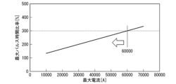
- Example 13 the maximum current of the pulse process was excessive. This resulted in an excessive maximum pulse time ratio in Example 13.
- Example 16 the maximum current in the pulse process was insufficient. This resulted in an excessive maximum flat spot length in Example 16.
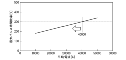
- Example 17 the average current of the pulse process was excessive. This resulted in an excessive maximum pulse time ratio in Example 17.
- Example 20 the average current in the pulse process was insufficient. This resulted in an excessive maximum flat spot length in Example 20.
- Example 59 the final flash velocity in the later flash step was insufficient. This resulted in an excessive maximum flat spot length in Example 59.
- Example 64 the amount of C was excessive. This resulted in an excessive maximum pulse time ratio in Example 64.
- Example 67 the amount of C was insufficient. As a result, the maximum flat spot length in Example 67 was excessive.
- Example 68 the amount of Mn was excessive. This resulted in the maximum flat spot length being excessive in Example 68.
- Example 71 the amount of Cr was excessive. This resulted in the maximum flat spot length being excessive in Example 71.
Landscapes
- Engineering & Computer Science (AREA)
- Mechanical Engineering (AREA)
- Butt Welding And Welding Of Specific Article (AREA)
- Heat Treatment Of Articles (AREA)
- Arc Welding In General (AREA)
Abstract
Description
(2)上記(1)に記載のフラッシュバット溶接レールの製造方法では、好ましくは、前記パルス工程における最小電流を0.12A/mm2以上とする。
(3)上記(1)又は(2)に記載のフラッシュバット溶接レールの製造方法では、好ましくは、前記後期フラッシュ工程のフラッシュ長を5~50mmとする。
(4)上記(1)~(3)のいずれか一項に記載のフラッシュバット溶接レールの製造方法では、好ましくは、前記レールの前記化学成分が、単位質量%でV:0.001~0.300%、Ti:0.0008~0.0500%、Nb:0.001~0.050%、Cu:0.005~1.000%、Ni:0.01~1.00%、Ca:0.0005~0.0200%、REM:0.0005~0.0500%、Al:0.001~0.500%、及びMo:0.002~0.500%からなる群から選択される一種以上を含有する。
(S1)長手方向に沿って並べられた一対のレール1A、1Bの端面の間にフラッシュを生じさせて、これにより端面を平坦化する前期フラッシュ工程と、
(S2)一対のレール1A、1Bの端面の接触及び引き離しを繰り返し、これにより端面を予熱するパルス工程と、
(S3)一対のレール1A、1Bの端面の間にフラッシュを生じさせて、これにより端面を全体的に溶融させる後期フラッシュ工程と、
(S4)一対のレール1A、1Bの端面を突き当てて加圧し、これによりレールを接合するアプセット工程と、
を備える。さらに、本実施形態に係るフラッシュバット溶接レールの製造方法では、パルス工程における周波数を1~10Hzとし、パルス工程における最大電流を2.33~6.98A/mm2とし、パルス工程における平均電流を0.70~4.65A/mm2とし、後期フラッシュ工程における最終フラッシュ速度を0.2~3.4mm/secとし、レールの化学成分が、単位質量%でC:0.60~1.20%、Mn:0.1~2.0%、Cr:0.01~2.00%、Si:0.10~2.00%、P:0.020%以下S:0.020%以下、及びN:0.003~0.020%を含有し、残部はFe及び不純物を含み、パルス工程において、平均電流と通電時間との積である積算電流の、単位kA・sec/mm2での上限値を(8×周波数-480×C含有量+1400)/8600とし、パルス工程において、積算電流の単位kA・sec/mm2での下限値を(3.5×周波数-180×C含有量+55×Mn含有量+45×Cr含有量+300)/8600とする。
本実施形態に係るフラッシュバット溶接レールの製造方法を説明するに先立ち、用語の定義を述べる。
フラッシュバット溶接レール(溶接レール/welded rail):フラッシュバット溶接によって製造された、2以上のレールを溶接して得られたレールを意味する。フラッシュバット溶接レールは、母材部と溶接部とを備え、母材部は、溶接前のレールと同じ化学成分及び組織を有する。
圧着:事前に定められた周波数のレール前進及び後退制御において、突き合せられた2本のレールの端面(溶接面)がくっつき離れなくなること、もしくは端面が離れにくくなり、レールが後退するのに要する時間が事前に定められた時間と比較して長くなることを意味する。
計画パルス時間:溶接前に定められた、1回のパルスの実施に要する時間の計画値を意味する。
実績パルス時間:溶接の際の電流波形の実測値から測定される、1回のパルスの実施に要する時間の実績値を意味する。パルス工程においては、一対のレールが圧着されて、レールの引き離しが速やかに実施されない場合がある。従って、計画パルス時間と実績パルス時間とは必ずしも一致しない。
最大実績パルス時間:複数のパルスを有するパルス工程における、実績パルス時間の最大値である。
本実施形態に係るフラッシュバット溶接レールの製造方法を検討する際には、パルスフラッシュ方式のモバイル式FB溶接機を用いて溶接を行った。溶接機はプラッサー社製のモバイル式FB溶接機を用いた。しかし、このことは本実施形態に係る製造方法を実施するための溶接機種を限定するものではない。
レール素材は、AREMA Chapter 4 “Rail”、UIC860-Rに規定されているように、Cを0.60~0.86質量%含有する共析組成又は過共析組成のレール鋼が一般的である。また最近では、フラッシュバット溶接レールの耐摩耗性を一層向上させるために、さらにCを高めたレール鋼も普及しつつある。また、フラッシュバット溶接レールが用いられる路線における貨車重量に応じて、フラッシュバット溶接レールの断面サイズが選択される。すなわち重量の重い貨車が通る区間では、剛性が高く、断面サイズの大きいレールが採用される。
フラッシュバット溶接レールに曲げ試験を実施することにより形成される破面には、脆性破面とは明らかに異なる、表面に凹凸のない部位(”フラットスポット”という)が一つ又は複数個存在し、これを目視で確認することができる。フラットスポットを分析すると、これがMn、Crなどの酸化物の集合体を含んでいることがわかる。従って、このフラットスポットは酸化物欠陥の一種である。フラットスポットは、曲げ試験におけるたわみ量、及び底部応力を低下させる原因となることが知られている。
フラットスポット最大長さと、曲げ時の底部応力との関係を図3に示す。底部応力は、一つ又は複数個あるフラットスポットの最大長さの影響を受ける。フラットスポットの最大長さの増加に伴い、フラッシュバット溶接レールの曲げ破断応力は低下する傾向を示す。フラットスポットの最大長さが12mmを超えると、曲げ時の底部破断応力は著しく低下し、溶接規格を満たさなくなることを本発明者らは明らかにした。そのため、フラッシュバット溶接レールの曲げ時の底部応力が規格を満足するには、最大フラットスポット長さを12mm以下にする必要があることを明らかにした。なお今回はフラットスポット最大長さと曲げ時の底部応力との関係を提示したが、フラットスポット最大長さとたわみ量との関係においても、同様な結果が得られた。
フラッシュバット溶接レールの曲げ試験において、破断時のたわみ量、及び底部応力を高めるためには、固定式FB溶接機を用いる場合には、溶接時の積算電流を高め、後期フラッシュ工程の開始前に端面全体の温度を高くすることが有効であることが知られている。これにより、後期フラッシュ工程で生成した酸下物をアプセット工程で排出させやすくすることができる。しかしながら、パルスフラッシュ方式のフラッシュバット溶接においては、積算電流を高めても、破断時のたわみ量、及び底部応力が規格を満足しない場合があった。
そこで発明者らは検討を重ねた結果、パルスフラッシュ方式のフラッシュバット溶接において積算電流を高めても、低たわみ量、低底部応力での破断が生じる原因を調査した。具体的には、パルスフラッシュ方式のフラッシュバット溶接におけるフラットスポットの生成機構を調査した。その結果、下記の知見を得た。
パルスフラッシュ方式のフラッシュバット溶接によって得られるフラッシュバット溶接レールの曲げ試験で、たわみ量、及び底部応力が規格を満足するためには、パルスフラッシュ方式特有の工程であるパルス工程の入熱影響因子と、フラットスポットとの関係を明らかにすることが有効であると本発明者らは考えた。入熱影響因子とは、積算電流、最大電流、平均電流、周波数などである。さらに、端面における酸化物が生成した部位の温度低下を防止するために、レール成分とフラットスポットとの関係を明らかにすることが有効であると発明者らは考えた。
(成分の個別の影響について)
発明者らは、フラッシュバット溶接レールの曲げ性能、及びフラットスポット最大長さに及ぼすレールの化学成分の影響を調査して、下記の知見を得た。化学成分の影響により、パルス工程において端面に酸化物が発生すると、酸化物が発生した部位の温度は低い。一方で、酸化物が生成していない部位の温度は高い。そのため、端面内で温度差が生じる。この温度差の影響が、後期フラッシュ工程、及びアプセット工程でも継続し、パルス工程の完了後に温度の低い部位では、後期フラッシュ工程で生成した酸化物がアプセット工程で排出され難くなる。これが、フラットスポット(酸化物欠陥)が生成する原因となる。そして、曲げ試験において、低底部応力で破断が生じる。そこで、化学成分が曲げ試験に及ぼす影響を評価するために、“パルス工程の終了後の端面における低温部の個数”を指標として用いた。なおパルス工程の終了後の端面における低温部の個数は、パルス工程の終了直後に端面を引き離して測定した。また、パルス工程時に端面に生成した酸化物は、後期フラッシュ工程の溶鋼の飛散とともに、外部に排出されると考える。
温度を測定するために用いる機器は、例えばサーモビュアー(物体表面の温度分布を非接触で測定する温度計)がある。サーモビュアーの必要な検出画素数は、横方向320画素以上、縦方向240画素以上とする。測定対象は、レールの高さ方向の中立線より下側の範囲とする。溶接レールの曲げ試験において、引張の応力が働くのは、中立線より下側であるため、当該範囲の温度を測定することによって、当該範囲に存在する酸化物を評価する必要があると考えられた。
図4A及び図4Bに示すように、サーモビュアーにより測定された温度データの評価においては、幅方向10mm×高さ方向2mmの範囲を、1つの評価単位とした。そして、この評価単位を複数の所定の位置に配置し、それぞれにおける温度データを用いて評価した。図4Aはレール端面の概略図であり、図4Bは、レール端面のうち、高さ方向の中立線より下側の範囲の概略図である。図4Aにおける破線で囲まれた矩形領域が、図4Bである。図4A及び図4Bにおいて、符号Aが付された一点鎖線はレール端面の幅方向中心であり、符号Bが付された実線はレール端面の下端、即ちレールの足裏面であり、符号Oが付された領域は測定除外領域である。図4Bにおいて、符号C1が付された×印は、1つめの評価単位の中心であり、符号E1が付された破線によって囲まれた、幅10mm及び高さ2mmの矩形領域は、1つめの評価単位である。符号E2及び符号C2は、2つめの評価単位、及びその中心である。
評価単位の形状は、上述の通り、レールの端面の幅方向に沿って10mm、及び高さ方向に沿って2mmの矩形形状とした。
評価単位の位置については、以下の通りとした。まず、1つめの評価単位E1の中心C1を、レールの端面の幅方向中心A上、且つレール足裏面Bから上方3mmの位置に配置した。次に、1つめの中心C1を基準として、幅方向に2mmピッチ、高さ方向に2mmピッチの各点を、2つめ以降の評価単位の中心の位置とした。図4Bに記載されている、C1以外の×印が、2つめ以降の評価単位の中心の位置である。参考のために、2つめの評価単位E2も図4Bに記載した。ただし、3つめ以降の評価単位は省略した。なお、各評価単位は、幅方向端部において互いに重なり合うことになる。また、図4Bには評価位置の中心の位置を9個だけ記載し、10個め以降の記載は省略した。
種々のC量を適用したレールを溶接し、前述の通り、パルス工程の完了直後に端面を引き離し、サーモビュアーを用いて端面の温度を計測し、各評価単位における平均温度と最低温度との温度差を求めた。この時のC量と、温度差が50℃以上となった評価単位の個数との関係を図5に示す。レールのC量が0.6質量%以上の範囲では、C量の低下に伴い、温度差が50℃以上となった評価単位の個数は増加するが、その増加の割合は小さい。このことより、レールのC量は0.6質量%以上とする。さらに曲げ性能を高めるためには、好ましくは、レールのC量は0.7質量%以上とする。
種々のMn量を適用したレールを溶接し、前述の通り、パルス工程の完了直後に端面を引き離し、サーモビュアーを用いて端面の温度を計測し、各評価単位における平均温度と最低温度との温度差を求めた。この時のMn量と、温度差が50℃以上となった評価単位の個数との関係を図6に示す。レールのMn量が2.0質量%以下の範囲では、Mn量の増加に伴い、温度差が50℃以上となった評価単位の個数は増加するが、その増加の割合は小さい。一方、Mn量が2.0質量%を上回ると、温度差50℃以上の評価単位の個数は著しく増加することを本発明者らは明らかにした。このことより、レールのMn量は2.0質量%以下とする。さらに曲げ性能を高めるためには、好ましくはレールのMn量は1.5質量%以下とする。
種々のCr量を適用したレールを溶接し、前述の通り、パルス工程の完了直後に端面を引き離し、サーモビュアーを用いて端面の温度を計測し、各評価単位における平均温度と最低温度との温度差を求めた。この時のCr量と、温度差が50℃以上となった評価単位の個数との関係を図7に示す。レールのCr量が2.0質量%以下の範囲では、Cr量の増加に伴い、温度差が50℃以上となった評価単位の個数は増加するが、その増加の割合は小さい。一方、Cr量が2.0質量%を上回ると、温度差50℃以上の評価単位の個数は著しく増加することを本発明者らは明らかにした。このことより、レールのCr量は2.0質量%以下とする。さらに曲げ性能を高めるためには、好ましくはレールのCr量は1.3質量%以下とする。
図5~図7に示される、化学成分と温度差50℃以上の評価単位の個数との関係の評価においては、パルス工程の完了後に温度測定を行ったので、後期フラッシュ工程及びアプセット工程は実施されなかった。本発明者らは、温度差50℃以上の評価単位の個数がフラッシュバット溶接レールに及ぼす影響を確認するために、上述の評価における溶接条件を用いながら、種々のレールに対して後期フラッシュ工程、及びアプセット工程を行い、種々のフラッシュバット溶接レールを製造した。溶接後に、加速冷却及び再加熱などの熱処理は行われなかった。そして、種々の継手におけるフラットスポット最大長さを測定し、これにより、温度差50℃以上の評価単位の個数と、フラットスポット最大長さとの関係を評価した。評価結果を図8に示す。平均温度と最低温度の温度差50℃以上となる評価単位数が10個未満の場合、フラットスポット最大長さは3mm程度の小さい値となった。一方、温度差50℃以上となる評価単位数が10個以上である場合、急激にフラットスポット最大長さは大きくなった。また平均温度と最低温度の温度差50℃以上となる評価単位数が40個を超えると、最大フラットスポット長さは21mm程度で飽和する傾向を示した。
パルス工程における周波数が大きすぎると、1パルス(1回のレールの前進、後退)当たりの通電時間が短くなる。そのため、1パルス当たりの温度上昇量が小さくなり、端面の温度が低くなる。そして、後期フラッシュ工程でも温度が十分に高くならず、後期フラッシュ工程で生成した酸化物がアプセット工程で排出され難くなり、酸化物欠陥(フラットスポット)が形成されやすくなる。そのため、パルス工程における周波数が大きすぎると、フラッシュバット溶接レールの曲げ試験において、低たわみ、低底部応力での破断が生じると考える。
フラットスポット最大長さは、C量、Mn量、Cr量の相互の影響を強く受けることがこれまでの検討によりわかった。また周波数の影響を強く受けることを把握した。さらに、発明者らの調査によると、C量、Mn量、Cr量、周波数に応じて積算電流を制御することで、フラットスポット長さが変化することを明らかにし、これらを関数として、フラットスポット最大長さが12mm以下となる範囲を積算電流の式(2)で求めた。
積算電流下限=3.5×周波数-180×C%+55×Mn%+45×Cr%+300・・式(2)
なお、式(2)においてC%、Mn%、及びCr%は、それぞれ単位質量%でのレールのC量、Mn量、及びCr量である。式(2)においてC量は0.6質量%以上、Mn量は2.0質量%以下、Cr量は2.0%質量以下、周波数は1Hz以上の範囲である。
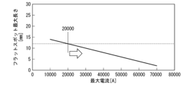
パルス工程の最大電流と、フラットスポット最大長さとの関係を図10に示す。最大電流の低下に伴い、フラットスポット最大長さは増加する傾向を示した。フラットスポット最大長さが12mmとなるのは、最大電流が2.33A/mm2であることがわかった。そのためパルス工程の最大電流は2.33A/mm2以上とする。さらに曲げ性能を高めるためには、好ましくは、パルス工程の最大電流は2.91A/mm2以上とする。
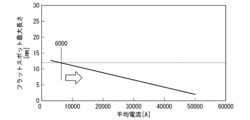
パルス工程の平均電流と、フラットスポット最大長さとの関係を図11に示す。平均電流の低下に伴い、フラットスポット最大長さは増加する傾向を示した。フラットスポット最大長さが12mmとなるのは平均電流が6,000A(0.70A/mm2)であることがわかった。そのためパルス工程の平均電流の範囲は0.70A/mm2以上とする。さらに曲げ性能を高めるためには、好ましくは、パルス工程の平均電流の範囲は1.74A/mm2以上とする。
事前に定められた周波数で行われるレールの前進及び後退の制御において、突き合せられた2本のレールの端面(溶接面)がくっつき離れなくなること、もしくは端面が離れにくくなり後退するのに要する時間が事前に定められた時間と比較して長くなることを、圧着と呼ぶ。一般的に、端面への積算電流が過剰に多く、これにより端面の温度が著しく高くなる場合に、圧着が生じやすくなる。
・パルス工程において、積算電流(最大電流、平均電流)が大きい場合に、端面への入熱量が大きくなる。端面の温度が高くなった結果、圧着が生じやすい。
・パルス工程において周波数が小さいと、1回の前進時における高温となる時間が長くなり、端面の温度上昇量が大きくなった結果、圧着が生じやすい。
・予熱フラッシュ方式のフラッシュバット溶接の予熱工程とは異なり、パルスフラッシュ方式のフラッシュバット溶接のパルス工程では、レールの前進及び後退を繰り返すなかで、最大限レールが前進した場合でも端面すべてが接触するわけではなく、部分的な接触にとどまる。このことが、圧着の生成に大きく影響を及ぼす。とくに、端面内に部分的に電気抵抗の高い部位が存在すると、当該部におけるジュール発熱が高くなり、当該部及びその周辺部の温度が高くなる。その結果、圧着が生じやすい。
レールの前進及び後退制御における力(油圧)が固定式FB溶接機と比較して小さい、パルスフラッシュ方式のフラッシュバット溶接において、パルス工程における圧着防止のためには、パルスフラッシュ方式固有の対策が必要と本発明者らは考えた。具体的には、圧着対策として、端面の温度過上昇を防止するために、パルス工程の入熱影響因子(最大電流、平均電流、積算電流、周波数など)と圧着の関係を明らかにすること、さらに電気抵抗の高い部位における温度過上昇を防止するために、レール成分の化学成分と圧着の関係を明らかにすることが有効であると発明者らは考えた。
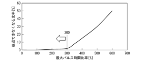
最大パルス時間比率と、パルス工程において前進した後に後退できなくなる比率との関係を図12に示す。最大パルス時間とは、上述されたように、実績パルス時間の最大値である最大実績パルス時間を、溶接前に定められたパルス時間の計画値である計画パルス時間で割った値である。最大パルス時間は、計画値と実績値との乖離を示す指標である。
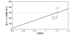
レールのC量と、パルス工程における最大パルス時間比率との関係を図13に示す。C量の増加に伴い、最大パルス時間比率は増加する傾向を示す。最大パルス時間比率が300%となるのは、C量が1.2質量%の時である。そのためC量は1.2質量%以下とする。さらに圧着の発生を抑制するには、好ましくはC量の範囲は1.1質量%以下とする。
パルス工程における周波数と、最大パルス時間比率との関係を図14に示す。周波数の低下に伴い、最大パルス時間比率は増加する傾向を示し、最大パルス時間比率が300%となるのは、周波数が1Hzのときであることがわかった。そのため周波数の範囲は1Hz以上とする。さらに圧着の発生を抑制するには、好ましくは周波数の範囲は3Hz以上とする。
圧着の発生は、C量、及び周波数の影響を強く受けることがこれまでの検討によりわかった。さらに、発明者らの調査によると、C量、周波数に応じて積算電流を制御することで、圧着の発生に強く影響を及ぼすことを明らかにした。そして、これらを関数として、圧着の生じない積算電流(単位:kA・sec/mm2)の範囲を式(3)で求めた
積算電流上限=(8×周波数-480×C質量%+1400)/8600・・式(3)
なお、式(3)においてC量は1.2質量%以下、周波数は1Hz以上の範囲である
パルス工程における最大電流と、最大パルス時間比率の関係を図15に示す。最大電流の増加に伴い、最大パルス時間比率は増加する傾向を示し、最大パルス時間比率が300%となるのは、最大電流が6.98A/mm2のときであることがわかった。そのため最大電流の範囲は6.98A/mm2以下とする。さらに圧着の発生を抑制するには、好ましくは最大電流の範囲は5.23A/mm2以下とする。なお、このときのレールの断面積は8600mm2であり、積算電流は500kA・sec(0.06kA・sec/mm2)、平均電流は18,000A(2.09A/mm2)、C量は0.9質量%、Mn量は1.0質量%、Cr量は0.5質量%、周波数は5Hzである。最大電流の増大に伴い最大パルス時間が増加する理由は、前述の通り、最大電流が大きいと端面への入熱量が大きくなり、端面の温度が高くなった結果、端面がくっつきやすくなったためと考える。
パルス工程における平均電流と、最大パルス時間比率との関係を図16に示す。平均電流の増加に伴い、最大パルス時間比率は増加する傾向を示し、最大パルス時間比率が300%となるのは、平均電流が4.65A/mm2のときであることがわかった。そのため平均電流の範囲は4.65A/mm2以下とする。さらに圧着の発生を抑制するには、好ましくは平均電流の範囲は3.26A/mm2以下とする。
上述の項目kに記載の圧着防止の観点より、パルス工程における周波数の下限値は1Hzとする。さらに圧着の発生を抑制するには、好ましくは周波数の範囲は2Hz以上、3Hz以上、又は4Hz以上とする。また、上述の項目eに記載の酸化物欠陥抑制の観点より、パルス工程における周波数の上限値は10Hzとする。酸化物を一層抑制する観点から、パルス工程における周波数の上限値を9Hz以下、8Hz以下、又は6Hz以下とすることが好ましい。周波数の最も好ましい範囲は3Hz以上、6Hz以下である。
上述の項目gに記載の酸化物欠陥抑制の観点より、パルス工程における最大電流の下限値は2.33A/mm2とする。さらに曲げ性能を高めるためには、好ましくは、パルス工程の最大電流は2.50A/mm2以上、は2.91A/mm2以上、または3.20A/mm2とする。また、上述の項目mに記載の圧着防止の観点より、パルス工程における最大電流の上限値は6.98A/mm2とする。さらに圧着の発生を抑制するには、好ましくは最大電流の範囲は6.00A/mm2以下、5.23A/mm2以下、又は4.80A/mm2以下とする。パルス工程における最大電流の最も好ましい範囲は2.91A/mm2以上、5.23A/mm2以下である。
上述の項目hに記載の酸化物欠陥抑制の観点より、パルス工程における平均電流の下限値は0.70A/mm2とする。好ましくは、パルス工程の平均電流の範囲は1.00A/mm2以上、1.74A/mm2以上、又は2.00A/mm2以上とする。また、上述の項目nに記載の圧着防止の観点より、パルス工程における平均電流の上限値は4.65A/mm2とする。さらに圧着の発生を抑制するには、好ましくは平均電流の範囲は4.00A/mm2以下、3.26A/mm2以下、または2.80A/mm2以下とする。パルス工程における平均電流の最も好ましい範囲は1.74A/mm2以上、3.26A/mm2以下である。
後期フラッシュ工程における最終フラッシュ速度とは、後期フラッシュ工程の最後の5秒間におけるフラッシュ速度の平均値を意味する。即ち、後期フラッシュ工程における最終フラッシュ速度とは、後期フラッシュ工程の最後の5秒間におけるレールの移動量を、5秒で割った値である。ただし、後期フラッシュ工程の時間が5秒未満である場合は、後期フラッシュ工程における最終フラッシュ速度とは、後期フラッシュ工程の開始から終了までのフラッシュ速度の平均値、即ち後期フラッシュ工程におけるレールの移動量である後期フラッシュ長を、後期フラッシュ工程の時間で割った値を意味する。
上述の項目b及び項目oに記載の酸化物欠陥抑制の観点より、C量の下限値は0.60質量%とする。C量は好ましくは0.65質量%以上、0.70質量%以上、又は0.80質量%以上である。一方、上述の項目jに記載の圧着防止の観点より、C量の上限値は1.20質量%とする。C量は好ましくは1.10質量%以下、1.00質量%以下、又は0.90質量%以下である。C量の最も好ましい範囲は0.70質量%以上、1.10質量%以下である。
上述の項目c及び項目oに記載の酸化物欠陥抑制の観点より、Mn量の上限値は2.00質量%とする。Mn量は好ましくは1.80質量%以下、1.50質量%以下、又は1.20質量%以下である。一方、Mnは焼き入れ性向上による硬度増の効果を発揮する元素である。Mn量が不足すると、この効果が得られない。そのため、Mn量の下限値は0.10質量%とする。Mn量は好ましくは0.20質量%以上、0.50質量%以上、又は0.80質量%以上である。Mn量の最も好ましい範囲は0.20質量%以上、1.80質量%以下である。
上述の項目d及び項目oに記載の酸化物欠陥抑制の観点より、Cr量の上限値は2.00質量%とする。Cr量は好ましくは1.80質量%以下、1.50質量%以下、又は1.20質量%以下である。一方、Cr量が少なすぎる場合、フラッシュバット溶接レールの硬度が得られない。そのため、Cr量の下限値は0.01質量%とする。Cr量は好ましくは0.20質量%以上、0.50質量%以上、又は0.80質量%以上である。Cr量の最も好ましい範囲は0.20質量%以上、1.30質量%以下である。
上述の項目lに記載の圧着防止の観点より、積算電流の上限値を、パルス工程における周波数、及びレールのC量の関数として規定した。
上述の項目fに記載の酸化物欠陥抑制の観点より、積算電流の下限値を、パルス工程における周波数、並びにレールのC量、Mn量、及びCr量の関数として規定した。
パルス工程において、レールを後退させて、2つの端面を完全に引き離した場合、電流値は0A/mm2となる。従って、パルス工程における電流の最小値は0Aである。しかしながら、レールが完全に引き離される前にレールの後退を中止し、これを前進させた場合、電流値が0A/mm2まで低下しないことがある。
後期フラッシュ工程のフラッシュ長、即ち後期フラッシュ長とは、後期フラッシュ工程の開始から終了までのレールの移動量である。前述の通り、後期フラッシュ工程における後期フラッシュ速度には最適な範囲がある。しかしながら、後期フラッシュ長を長くすることにより、溶接時間(フラッシュ長/フラッシュ速度)が長くなり、端面の温度がいっそう高くなり、生成した酸化物をアプセット工程で外部に排出する効果が一層高められる。そのため、後期フラッシュ長の下限値は5mmとすることが好ましい。後期フラッシュ長を6mm以上、8mm以上、又は10mm以上とすることがさらに好ましい。
Siは、パーライト組織中のフェライト相を固溶強化して、母材の高強度化に寄与する元素である。この効果を得るために、レールにはSiが0.10%以上2.00%以下含有される。Si量は好ましくは1.80質量%以下、1.50質量%以下、又は1.20質量%以下である。Si量が0.10%未満ではその効果が得られず、2.00%超では材料が脆化しやすくなる。Si量は好ましくは0.20質量%以上、0.50質量%以上、又は0.80質量%以上である。Si量の一層好ましい範囲は0.20%以上1.50%以下である
Alは、レールに脱酸元素として含まれる。また、Alはパーライト組織の硬さの差を低減し、レール柱部の疲労強度を向上させる元素である。そのため、Alは0.001%以上である。Al量は好ましくは0.100質量%以上、0.120質量%以上、又は0.150質量%以上である。一方、粗大な酸化物や粗大なマルテンサイトの生成を抑制し、疲労強度を一層向上させる観点から、Alは0.500%以下とする。Al量は好ましくは0.450質量%以下、0.400質量%以下、又は0.300質量%以下である。一層好ましい範囲は、Alは0.005%以上0.100%以下である。
<S:0.020質量%以下>
<N:0.003~0.020質量%>
P及びSは鋼中の不純物である。P及びSが多いと、鋼の靭性が低下し、フラッシュバット溶接レールの疲労強度が低下する。そのため、溶接レールの疲労強度を高めるため、Pは0.020%以下、Sは0.020%以下とする。Pの好ましい範囲は0.010%以上、0.018%以下、Sの好ましい範囲は0.008%以上、0.018%以下である。なお、P量及びS量の下限は特に限定されず、0%でもよい。一方、精錬コストの改善のために、P量及びS量それぞれを0.001質量%以上、0.001質量%以上、又は0.010質量%以上としてもよい。
<好ましくは、Ti:0.0008~0.0500質量%>
<好ましくは、Nb:0.001~0.050質量%>
V、Ti、及びNbは、溶接母材として用いられるレールにおいて必須ではない。そのため、V量、Ti量、及びNb量は0%であってもよい。一方、V、Ti、及びNbは析出強化により鋼の硬度を高め、フラッシュバット溶接レールの疲労強度を向上させる元素である。そのため、必要に応じ、Vは0.001%以上0.300%以下、Tiは、0.0008%以上0.0500%以下、Nbは0.001%以上0.050%以下を、レールに含有させてもよい。Vは0.001%未満、Tiは、0.0008%未満、Nbは0.001%未満では硬度を高め、疲労強度を向上させる効果が得られない。また、粗大な窒化物の生成を抑制し、フラッシュバット溶接レールの疲労強度を一層高める観点から、Vは0.300%以下、Tiは0.0500%以下、Nbは0.050%以下とすることが好ましい。一層好ましい範囲は、Vは0.005%以上0.200%以下、Tiは0.0030%以上0.0400%以下、Nbは0.003%以上0.030%以下である。
<Ni:好ましくは、0.01~1.00質量%>
Cu、及びNiは、本実施形態に係る製造方法のレールにおいて必須ではない。そのため、Cu量、及びNi量は0%であってもよい。一方、Cu、及びNiは固溶強化により鋼の硬度を高め、フラッシュバット溶接レールの疲労強度を向上させる元素である。そのため、必要に応じ、Cuは0.005%以上1.000%以下、Niは0.01%以上1.00%以下をレールに含有させてもよい。Cuは0.005%未満、Niは0.01%未満では硬度を高め、疲労強度を向上させる効果が得られない。また、過剰な固溶強化による脆化を抑制し、レール鋼の延性を一層高める観点から、Cuは1.000%以下、Niは1.00%以下とすることが好ましい。一層好ましい範囲は、Cuは0.010%以上0.600%以下、Niは0.02%以上0.60%以下である。
<好ましくは、REM:0.0005~0.0500質量%>
Ca、及びREMは、本実施形態に係る製造方法のレールにおいて必須ではない。そのため、Ca量、及びREM量は0%であってもよい。一方、Caは、Sとの結合力が強く、硫化物を形成する。この硫化物がMnSを微細に分散させることで、レールの疲労強度を一層向上させる。REMは、酸化物やMnSの生成核として作用する。これらがMnSを微細に分散させることで、レールの疲労強度を一層向上させる。そのため、必要に応じ、Caは0.0005%以上0.0200%以下、REMは、0.0005%以上0.0500以下をレールに含有させてもよい。Caは0.0005%未満、REMは、0.0005%未満では疲労強度を向上させる効果が得られない。また、粗大な酸化物及び粗大な酸硫化物の生成を抑制し、疲労強度を一層向上させる観点から、Caは0.0200%以下、REMは0.0500%以下とすることが好ましい。一層好ましい範囲は、Caは0.0008%以上0.0180%以下、REMは0.0010%以上0.0450%以下である。なお、REMとはCe、La、Pr又はNd等の希土類元素である。上記のREM含有量の上下限値は、これらの全REM元素の含有量の総和を限定するものである。
Moは、本実施形態に係る製造方法のレールにおいて必須ではない。そのため、Mo量は0%であってもよい。一方、Moは、パーライト組織のラメラ間隔(フェライト相とセメンタイト相の間隔)を微細化することにより、鋼を高硬度化し、フラッシュバット溶接レールの疲労強度を向上させる元素である。そのため、必要に応じ、Moは0.002%以上0.500%以下含有させてもよい。Moが0.002%未満である場合、硬度を高め、疲労強度を向上させる効果が得られない。一方、粗大な酸化物や粗大なマルテンサイトの生成を抑制し、疲労強度を一層向上させる観点から、Moは0.500%以下とすることが好ましい。一層好ましい範囲は、Moは0.010%以上0.300%以下である。
本実施形態に係るフラッシュバット溶接レールの製造方法において、上述した条件が満たされる限り、種々の溶接条件を採用することができる。例えば前期フラッシュ工程においては、パルス工程に供しうる程度にレールの端面を平坦化可能な通常の条件を、適宜採用することができる。アプセット工程においても、正常な溶接部を形成可能な通常の条件を、適宜採用することができる。例えば、アプセット工程における加圧力は特に限定されないが、酸化物の排出能力を一層向上させる観点から、55MPa以上、58MPa以上、又は60MPa以上とすることが好ましい。また、設備能力を考慮すると、アプセット工程における加圧力を120MPa以下、100MPa以下、又は82MPa以下とすることが好ましい。パルス工程、及び後期フラッシュ工程においても、上述されなかった溶接条件については、通常の条件を適宜採用することができる。フラッシュバット溶接レールの製造方法が、バリを除去する工程、溶接部に後熱処理をする工程などの追加工程を備えてもよい。
曲げ試験は、米国鉄道工学及び保線協会(American Railway Engineering and Maintenance-of-Way Association)の規格:AREMA-sec.2.3.3.6に準拠して行う。すなわち、図17に示すように、溶接部を中心として支点間1200mmで溶接レールを支える。そして、溶接レール上方から、溶接部を中心として間隔300mmで、溶接レールに荷重を加える。溶接レールが破断するまで、荷重を増大させる。そして、破断時の溶接レールのたわみ量、及び破断時の荷重に基づき、破断時の溶接レール底部の長手方向応力(底部応力)を測定する。破断時のたわみ量は0.75inch以上、底部応力は125kbp/inch2以上が合格である。本実施形態に係る製造方法によって得られるフラッシュバット溶接レールは、溶接部においてフラットスポットの形成が極めて効果的に抑制されているので、上述の合否基準を満たすことができる。
積算電流上限:8×周波数-480×C質量%+1400
積算電流下限:3.5×周波数-180×C質量%+55×Mn質量%+45×Cr質量%+300
ここで、周波数とは、パルス工程における周波数であり、C質量%、Mn質量%及びCr質量%とは、単位質量%での、レールの化学成分におけるC、Mn、及びCr含有量である。積算電流、及びその上下限値に関しては、断面積を考慮した値の記載を省略した。
(最大パルス時間比率)
120%以下:A
120%超300%以下:B
300%超:X
最大パルス時間比率がA又はBとなった例は、溶接中の端面の圧着が抑制された例と判断した。
(フラットスポット最大長さ)
5mm以下:A
5mm超8mm以下:B
8mm超12mm以下:C
12mm超:X
なお、フラットスポットの評価において、長さが1.0mm未満のフラットスポットは評価対象とはしなかった。フラットスポット最大長さがA、B、又はCとなった例は、フラッシュバット溶接レールが曲げ試験の規格を満たす例と判断した。

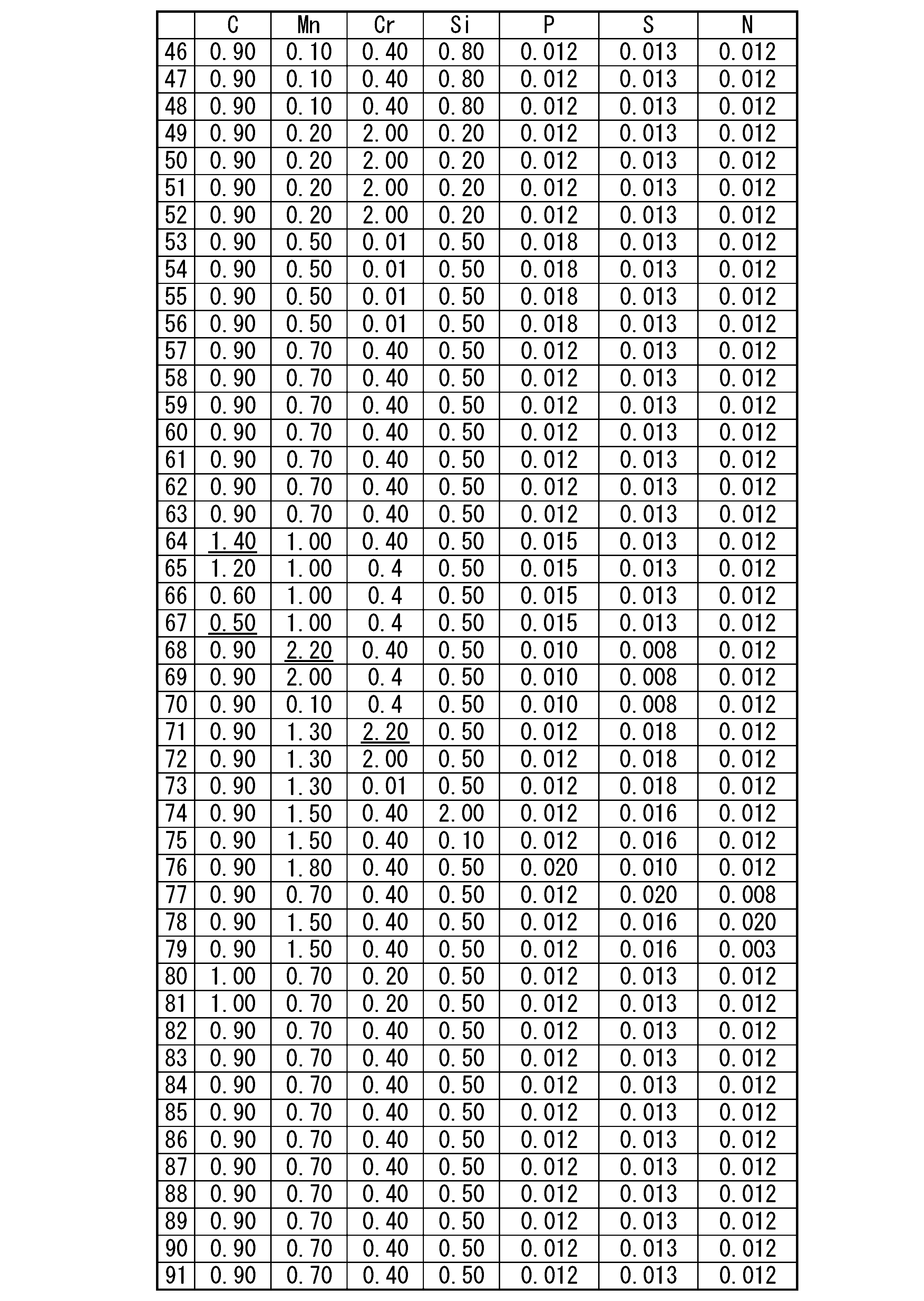
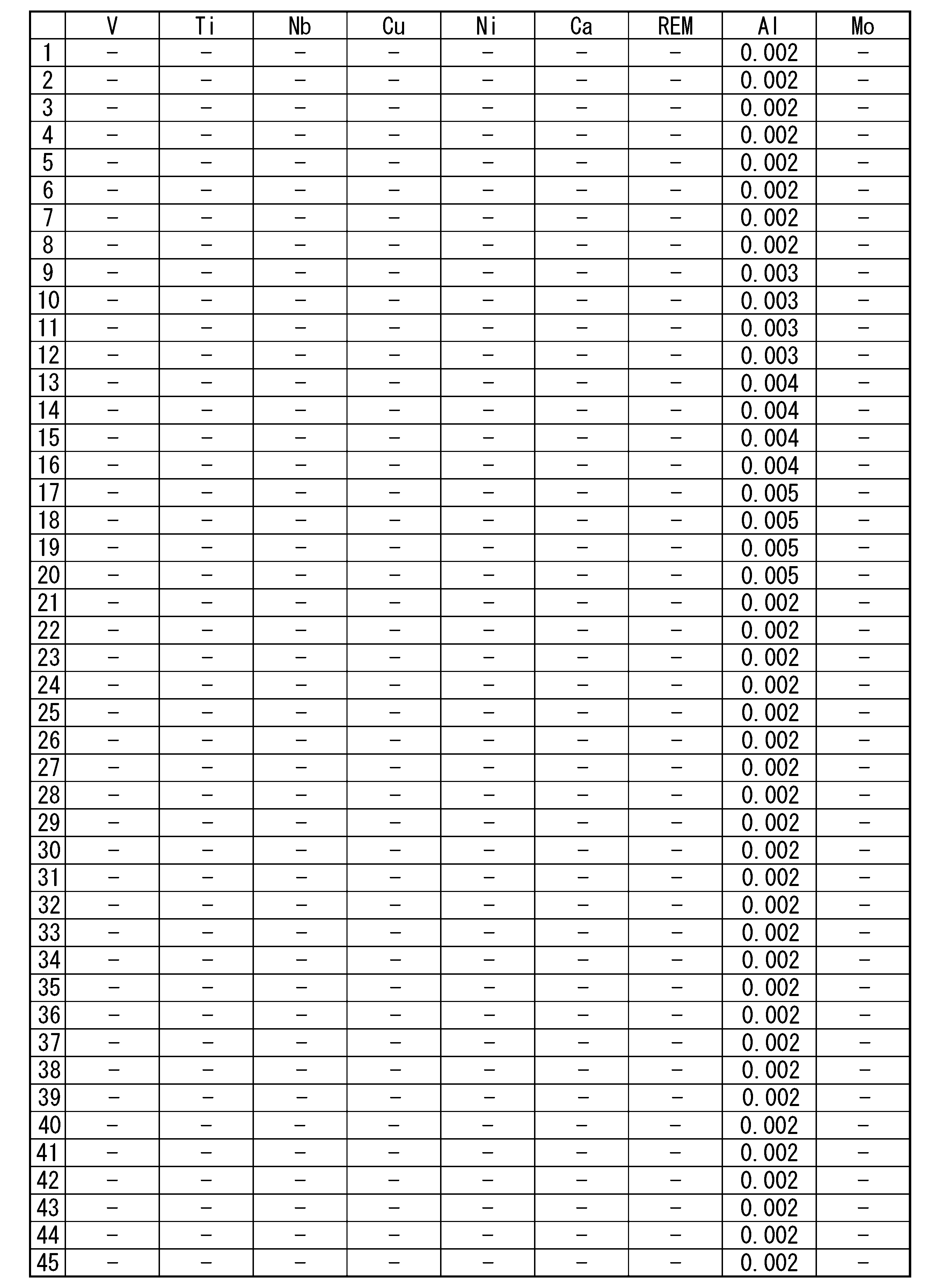
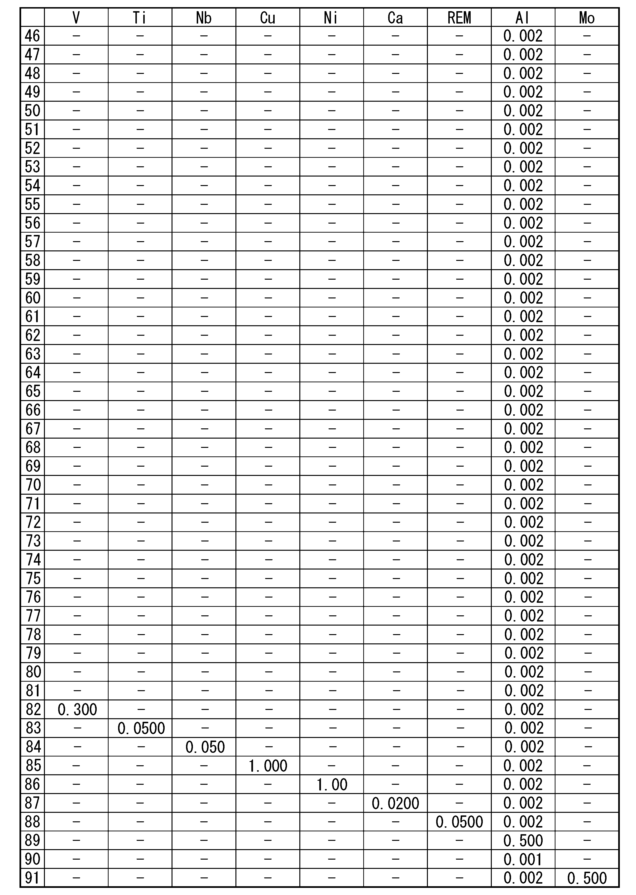
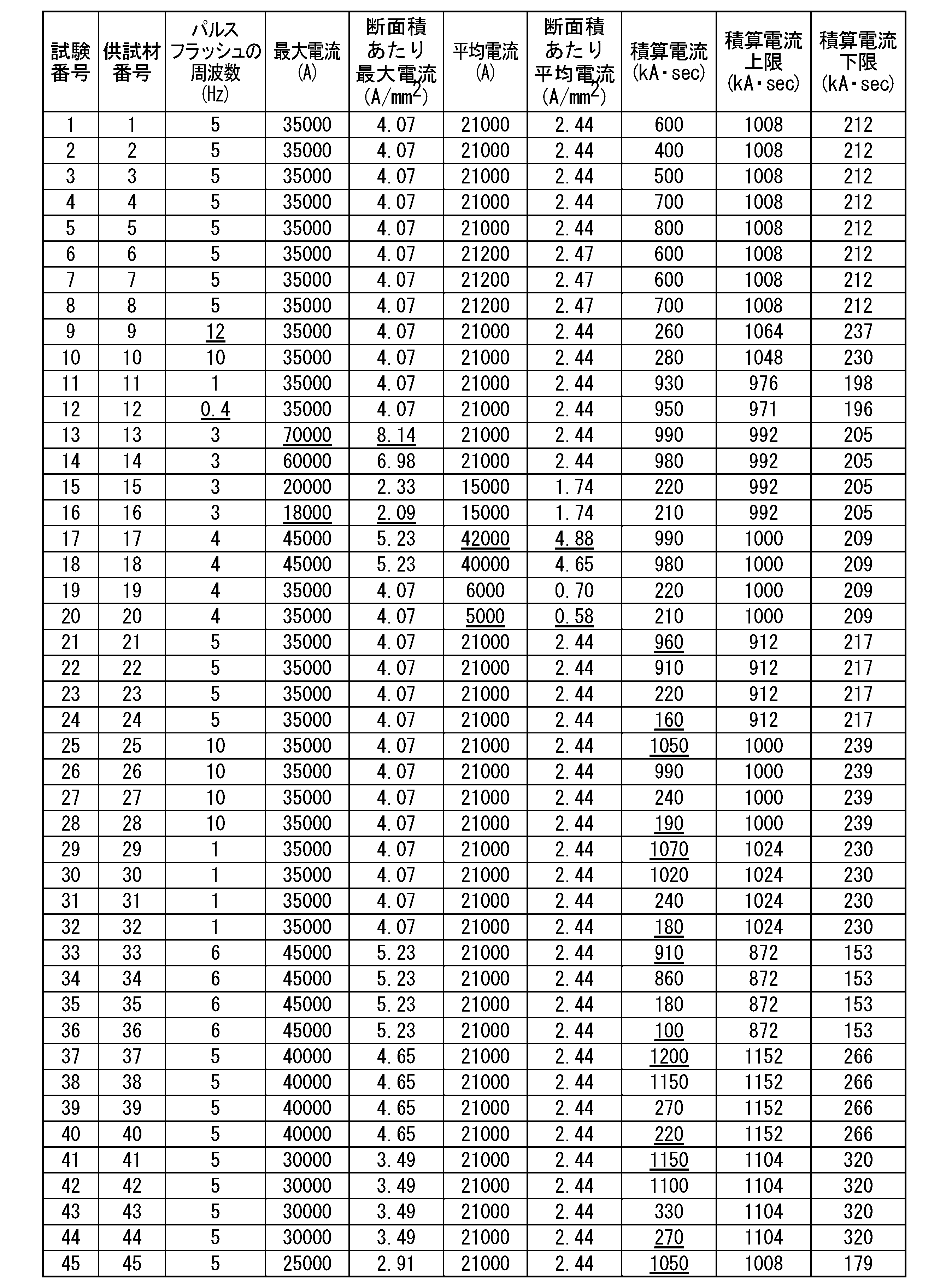
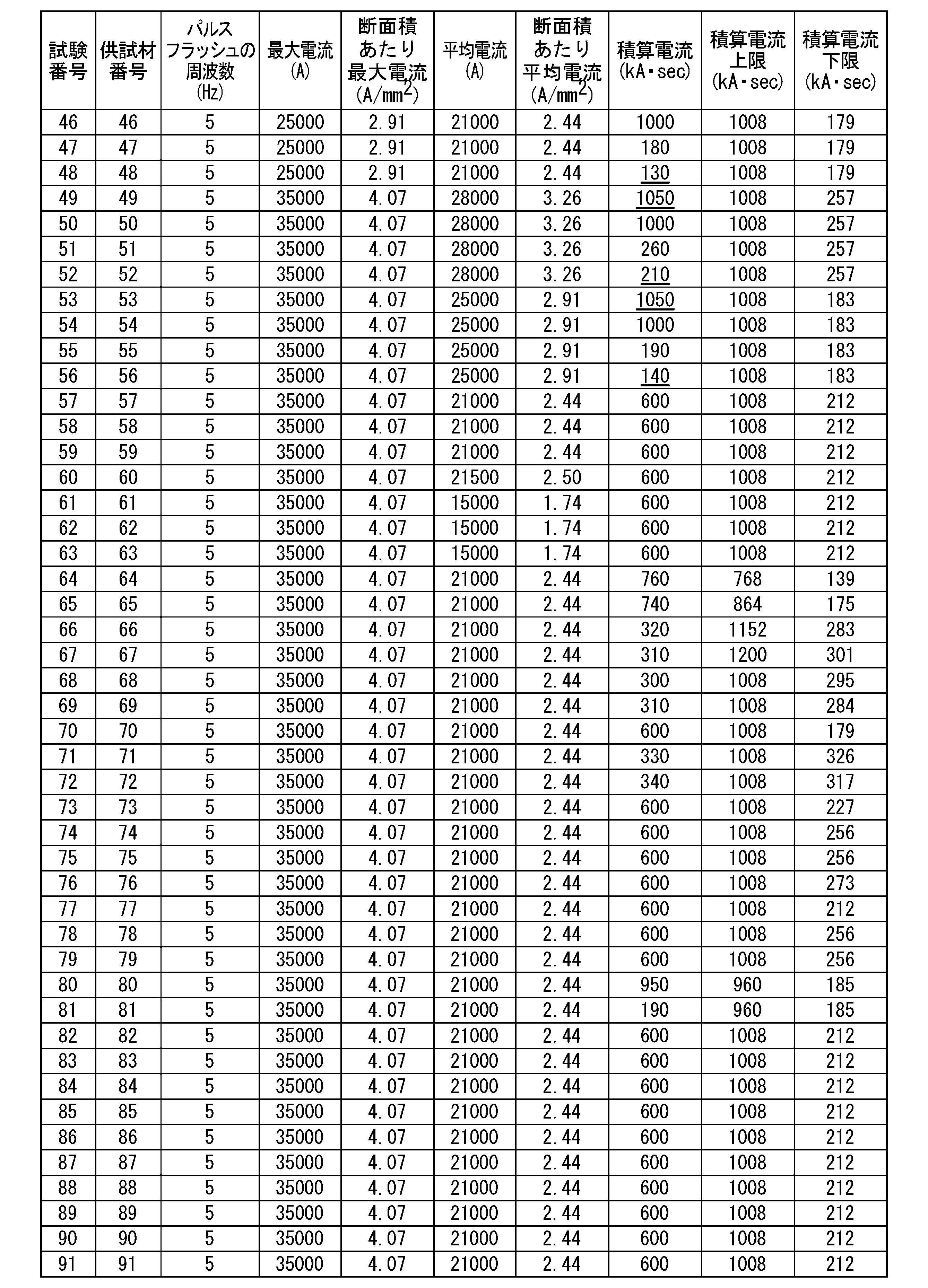
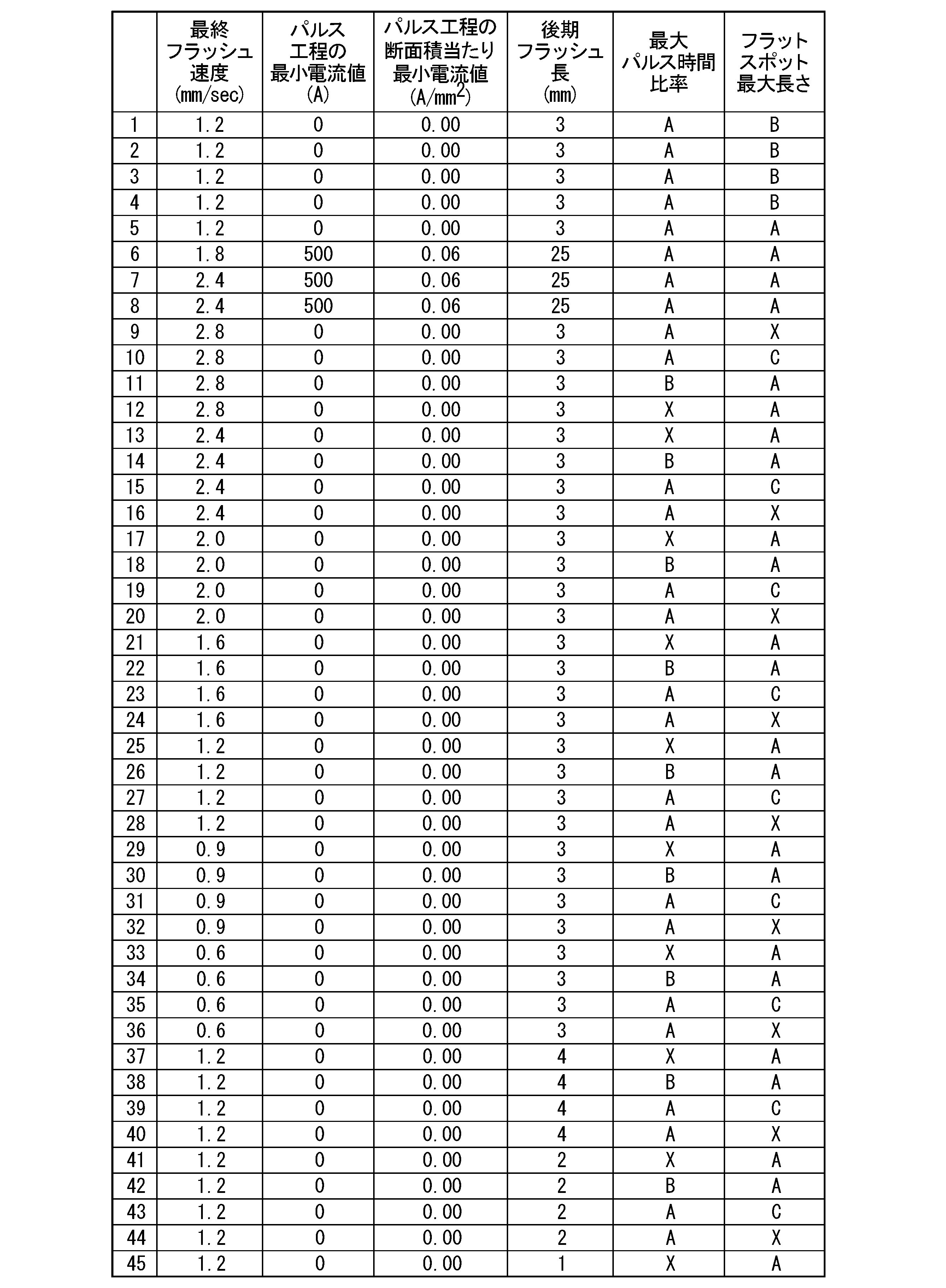

2 電極
3 バリ
Claims (4)
- 長手方向に沿って並べられた一対のレールの端面の間にフラッシュを生じさせて、これにより前記端面を平坦化する前期フラッシュ工程と、
一対の前記レールの前記端面の接触及び引き離しを繰り返し、これにより前記端面を予熱するパルス工程と、
一対の前記レールの前記端面の間にフラッシュを生じさせて、これにより前記端面を全体的に溶融させる後期フラッシュ工程と、
一対の前記レールの前記端面を突き当てて加圧し、これにより前記レールを接合するアプセット工程と、
を備え、
前記パルス工程における周波数を1~10Hzとし、
前記パルス工程における最大電流を2.33~6.98A/mm2とし、
前記パルス工程における平均電流を0.70~4.65A/mm2とし、
前記後期フラッシュ工程における最終フラッシュ速度を0.2~3.4mm/secとし、
前記レールの化学成分が、単位質量%で
C:0.60~1.20%、
Mn:0.1~2.0%、
Cr:0.01~2.00%、
Si:0.10~2.00%、
Al:0.001~0.500%、
P:0.020%以下
S:0.020%以下、
N:0.003~0.020%、
V:0~0.300%、
Ti:0~0.0500%、
Nb:0~0.050%
Cu:0~1.000%、
Ni:0~1.00%、
Ca:0~0.0200%、
REM:0~0.0500%、及び
Mo:0~0.500%
を含有し、残部はFe及び不純物を含み、
前記パルス工程において、前記平均電流と通電時間との積である積算電流の、単位kA・sec/mm2での上限値を(8×前記周波数-480×C含有量+1400)/8600とし、
前記パルス工程において、前記積算電流の単位kA・sec/mm2での下限値を(3.5×前記周波数-180×C含有量+55×Mn含有量+45×Cr含有量+300)/8600とする
フラッシュバット溶接レールの製造方法。 - 前記パルス工程における最小電流を0.12A/mm2以上とすることを特徴とする請求項1に記載のフラッシュバット溶接レールの製造方法。
- 前記後期フラッシュ工程のフラッシュ長を5~50mmとすることを特徴とする請求項1又は2に記載のフラッシュバット溶接レールの製造方法。
- 前記レールの前記化学成分が、単位質量%で
V:0.001~0.300%、
Ti:0.0008~0.0500%、
Nb:0.001~0.050%、
Cu:0.005~1.000%、
Ni:0.01~1.00%、
Ca:0.0005~0.0200%、
REM:0.0005~0.0500%、
Al:0.001~0.500%、及び
Mo:0.002~0.500%
からなる群から選択される一種以上を含有することを特徴とする請求項1又は2に記載のフラッシュバット溶接レールの製造方法。
Priority Applications (3)
| Application Number | Priority Date | Filing Date | Title |
|---|---|---|---|
| JP2023532453A JP7364992B1 (ja) | 2023-02-10 | 2023-02-10 | フラッシュバット溶接レールの製造方法 |
| AU2023428946A AU2023428946B2 (en) | 2023-02-10 | 2023-02-10 | Method of manufacturing flash-butt welded rail |
| PCT/JP2023/004601 WO2024166374A1 (ja) | 2023-02-10 | 2023-02-10 | フラッシュバット溶接レールの製造方法 |
Applications Claiming Priority (1)
| Application Number | Priority Date | Filing Date | Title |
|---|---|---|---|
| PCT/JP2023/004601 WO2024166374A1 (ja) | 2023-02-10 | 2023-02-10 | フラッシュバット溶接レールの製造方法 |
Publications (1)
| Publication Number | Publication Date |
|---|---|
| WO2024166374A1 true WO2024166374A1 (ja) | 2024-08-15 |
Family
ID=88328443
Family Applications (1)
| Application Number | Title | Priority Date | Filing Date |
|---|---|---|---|
| PCT/JP2023/004601 Ceased WO2024166374A1 (ja) | 2023-02-10 | 2023-02-10 | フラッシュバット溶接レールの製造方法 |
Country Status (3)
| Country | Link |
|---|---|
| JP (1) | JP7364992B1 (ja) |
| AU (1) | AU2023428946B2 (ja) |
| WO (1) | WO2024166374A1 (ja) |
Citations (5)
| Publication number | Priority date | Publication date | Assignee | Title |
|---|---|---|---|---|
| JPS59147782A (ja) * | 1983-02-10 | 1984-08-24 | Nippon Steel Corp | フラツシユバツト溶接方法 |
| WO2011052562A1 (ja) * | 2009-10-30 | 2011-05-05 | 新日本製鐵株式会社 | レール鋼のフラッシュバット溶接方法 |
| JP2012101280A (ja) * | 2010-10-14 | 2012-05-31 | Nippon Steel Corp | レール鋼のフラッシュバット溶接方法 |
| JP6822612B1 (ja) * | 2019-02-19 | 2021-01-27 | Jfeスチール株式会社 | レールの製造方法 |
| WO2022071007A1 (ja) * | 2020-09-30 | 2022-04-07 | 日本製鉄株式会社 | 溶接レール |
-
2023
- 2023-02-10 WO PCT/JP2023/004601 patent/WO2024166374A1/ja not_active Ceased
- 2023-02-10 JP JP2023532453A patent/JP7364992B1/ja active Active
- 2023-02-10 AU AU2023428946A patent/AU2023428946B2/en active Active
Patent Citations (5)
| Publication number | Priority date | Publication date | Assignee | Title |
|---|---|---|---|---|
| JPS59147782A (ja) * | 1983-02-10 | 1984-08-24 | Nippon Steel Corp | フラツシユバツト溶接方法 |
| WO2011052562A1 (ja) * | 2009-10-30 | 2011-05-05 | 新日本製鐵株式会社 | レール鋼のフラッシュバット溶接方法 |
| JP2012101280A (ja) * | 2010-10-14 | 2012-05-31 | Nippon Steel Corp | レール鋼のフラッシュバット溶接方法 |
| JP6822612B1 (ja) * | 2019-02-19 | 2021-01-27 | Jfeスチール株式会社 | レールの製造方法 |
| WO2022071007A1 (ja) * | 2020-09-30 | 2022-04-07 | 日本製鉄株式会社 | 溶接レール |
Also Published As
| Publication number | Publication date |
|---|---|
| JP7364992B1 (ja) | 2023-10-19 |
| JPWO2024166374A1 (ja) | 2024-08-15 |
| AU2023428946B2 (en) | 2026-05-28 |
| AU2023428946A1 (en) | 2025-06-19 |
Similar Documents
| Publication | Publication Date | Title |
|---|---|---|
| JP4902021B2 (ja) | レール鋼のフラッシュバット溶接方法 | |
| JP5659965B2 (ja) | レール鋼のフラッシュバット溶接方法 | |
| KR102589430B1 (ko) | 저항 스폿 용접부 및 저항 스폿 용접 방법, 그리고 저항 스폿 용접 조인트 및 저항 스폿 용접 조인트의 제조 방법 | |
| JP5987982B2 (ja) | スポット溶接継手及びスポット溶接方法 | |
| JP5467480B2 (ja) | 溶接構造部材及び溶接方法 | |
| JP5531845B2 (ja) | フラッシュバット溶接部近傍の後熱処理方法 | |
| KR102650264B1 (ko) | 저항 스폿 용접 방법 및 저항 스폿 용접 이음매의 제조 방법 | |
| JP7417170B2 (ja) | 溶接レール | |
| JP5206448B2 (ja) | 高強度薄鋼板の抵抗スポット溶接方法 | |
| JP2011251335A (ja) | レール鋼のフラッシュバット溶接方法 | |
| Kuchuk-Yatsenko et al. | Flash-butt welding of high-strength rails | |
| JP7364992B1 (ja) | フラッシュバット溶接レールの製造方法 | |
| JP7741463B1 (ja) | 溶接レールの製造方法 | |
| KR102425296B1 (ko) | 수직 방향 협개선 용접 조인트의 제조 방법 및 수직 방향 협개선 용접 조인트 | |
| JP3767487B2 (ja) | 溶接性に優れた熱延鋼板および冷延鋼板 | |
| JP5070866B2 (ja) | 熱延鋼板およびスポット溶接部材 | |
| JP7553882B1 (ja) | フラッシュバット溶接レールの製造方法 | |
| Allie | Microstructural Origin of Strength and Hardness of Flash-Butt Welded Railhead | |
| WO2023080135A1 (ja) | 溶接レール | |
| CN119839417A (zh) | 一种含微量合金元素r350ht高强热处理钢轨固定闪光焊焊接工艺 | |
| Nikitin | Flash welding Hadfield steel to rail steel |
Legal Events
| Date | Code | Title | Description |
|---|---|---|---|
| WWE | Wipo information: entry into national phase |
Ref document number: 2023532453 Country of ref document: JP |
|
| 121 | Ep: the epo has been informed by wipo that ep was designated in this application |
Ref document number: 23921203 Country of ref document: EP Kind code of ref document: A1 |
|
| WWE | Wipo information: entry into national phase |
Ref document number: AU2023428946 Country of ref document: AU |
|
| ENP | Entry into the national phase |
Ref document number: 2023428946 Country of ref document: AU Date of ref document: 20230210 Kind code of ref document: A |
|
| REG | Reference to national code |
Ref country code: BR Ref legal event code: B01A Ref document number: 112025012741 Country of ref document: BR |
|
| NENP | Non-entry into the national phase |
Ref country code: DE |
|
| 122 | Ep: pct application non-entry in european phase |
Ref document number: 23921203 Country of ref document: EP Kind code of ref document: A1 |
|
| ENP | Entry into the national phase |
Ref document number: 112025012741 Country of ref document: BR Kind code of ref document: A2 Effective date: 20250620 |