WO2024166352A1 - 作画支援プログラム、作画支援装置及び作画支援方法 - Google Patents
作画支援プログラム、作画支援装置及び作画支援方法 Download PDFInfo
- Publication number
- WO2024166352A1 WO2024166352A1 PCT/JP2023/004545 JP2023004545W WO2024166352A1 WO 2024166352 A1 WO2024166352 A1 WO 2024166352A1 JP 2023004545 W JP2023004545 W JP 2023004545W WO 2024166352 A1 WO2024166352 A1 WO 2024166352A1
- Authority
- WO
- WIPO (PCT)
- Prior art keywords
- parent
- parts
- child relationship
- setting
- child
- Prior art date
- Legal status (The legal status is an assumption and is not a legal conclusion. Google has not performed a legal analysis and makes no representation as to the accuracy of the status listed.)
- Ceased
Links
Images









Classifications
-
- G—PHYSICS
- G06—COMPUTING OR CALCULATING; COUNTING
- G06F—ELECTRIC DIGITAL DATA PROCESSING
- G06F8/00—Arrangements for software engineering
- G06F8/30—Creation or generation of source code
- G06F8/31—Programming languages or programming paradigms
- G06F8/315—Object-oriented languages
-
- G—PHYSICS
- G06—COMPUTING OR CALCULATING; COUNTING
- G06F—ELECTRIC DIGITAL DATA PROCESSING
- G06F3/00—Input arrangements for transferring data to be processed into a form capable of being handled by the computer; Output arrangements for transferring data from processing unit to output unit, e.g. interface arrangements
- G06F3/01—Input arrangements or combined input and output arrangements for interaction between user and computer
- G06F3/048—Interaction techniques based on graphical user interfaces [GUI]
- G06F3/0484—Interaction techniques based on graphical user interfaces [GUI] for the control of specific functions or operations, e.g. selecting or manipulating an object, an image or a displayed text element, setting a parameter value or selecting a range
-
- G—PHYSICS
- G06—COMPUTING OR CALCULATING; COUNTING
- G06F—ELECTRIC DIGITAL DATA PROCESSING
- G06F3/00—Input arrangements for transferring data to be processed into a form capable of being handled by the computer; Output arrangements for transferring data from processing unit to output unit, e.g. interface arrangements
- G06F3/01—Input arrangements or combined input and output arrangements for interaction between user and computer
- G06F3/048—Interaction techniques based on graphical user interfaces [GUI]
- G06F3/0484—Interaction techniques based on graphical user interfaces [GUI] for the control of specific functions or operations, e.g. selecting or manipulating an object, an image or a displayed text element, setting a parameter value or selecting a range
- G06F3/04842—Selection of displayed objects or displayed text elements
-
- G—PHYSICS
- G06—COMPUTING OR CALCULATING; COUNTING
- G06F—ELECTRIC DIGITAL DATA PROCESSING
- G06F3/00—Input arrangements for transferring data to be processed into a form capable of being handled by the computer; Output arrangements for transferring data from processing unit to output unit, e.g. interface arrangements
- G06F3/01—Input arrangements or combined input and output arrangements for interaction between user and computer
- G06F3/048—Interaction techniques based on graphical user interfaces [GUI]
- G06F3/0484—Interaction techniques based on graphical user interfaces [GUI] for the control of specific functions or operations, e.g. selecting or manipulating an object, an image or a displayed text element, setting a parameter value or selecting a range
- G06F3/04845—Interaction techniques based on graphical user interfaces [GUI] for the control of specific functions or operations, e.g. selecting or manipulating an object, an image or a displayed text element, setting a parameter value or selecting a range for image manipulation, e.g. dragging, rotation, expansion or change of colour
-
- G—PHYSICS
- G06—COMPUTING OR CALCULATING; COUNTING
- G06F—ELECTRIC DIGITAL DATA PROCESSING
- G06F3/00—Input arrangements for transferring data to be processed into a form capable of being handled by the computer; Output arrangements for transferring data from processing unit to output unit, e.g. interface arrangements
- G06F3/01—Input arrangements or combined input and output arrangements for interaction between user and computer
- G06F3/048—Interaction techniques based on graphical user interfaces [GUI]
- G06F3/0487—Interaction techniques based on graphical user interfaces [GUI] using specific features provided by the input device, e.g. functions controlled by the rotation of a mouse with dual sensing arrangements, or of the nature of the input device, e.g. tap gestures based on pressure sensed by a digitiser
- G06F3/0488—Interaction techniques based on graphical user interfaces [GUI] using specific features provided by the input device, e.g. functions controlled by the rotation of a mouse with dual sensing arrangements, or of the nature of the input device, e.g. tap gestures based on pressure sensed by a digitiser using a touch-screen or digitiser, e.g. input of commands through traced gestures
- G06F3/04883—Interaction techniques based on graphical user interfaces [GUI] using specific features provided by the input device, e.g. functions controlled by the rotation of a mouse with dual sensing arrangements, or of the nature of the input device, e.g. tap gestures based on pressure sensed by a digitiser using a touch-screen or digitiser, e.g. input of commands through traced gestures for inputting data by handwriting, e.g. gesture or text
-
- G—PHYSICS
- G06—COMPUTING OR CALCULATING; COUNTING
- G06F—ELECTRIC DIGITAL DATA PROCESSING
- G06F40/00—Handling natural language data
- G06F40/10—Text processing
-
- G—PHYSICS
- G06—COMPUTING OR CALCULATING; COUNTING
- G06F—ELECTRIC DIGITAL DATA PROCESSING
- G06F8/00—Arrangements for software engineering
- G06F8/30—Creation or generation of source code
- G06F8/38—Creation or generation of source code for implementing user interfaces
-
- G—PHYSICS
- G06—COMPUTING OR CALCULATING; COUNTING
- G06F—ELECTRIC DIGITAL DATA PROCESSING
- G06F8/00—Arrangements for software engineering
- G06F8/30—Creation or generation of source code
- G06F8/34—Graphical or visual programming
Definitions
- This disclosure relates to a drawing support program, a drawing support device, and a drawing support method.
- Patent Document 1 discloses a technique for setting parent-child relationships between shapes displayed on a screen in an application for creating GUI (Graphical User Interface) screens.
- This disclosure has been made to solve the problems described above, and aims to provide a drawing support program etc. that can reduce the effort required to set up multiple parts.
- the drawing support program comprises: an operation receiving means for receiving a selection operation for selecting a plurality of parts displayed on the screen; a selection order determination means for determining a selection order of the plurality of parts based on the selection operation received by the operation reception means and a positional relationship of the plurality of parts on the screen;
- the selection unit functions as a parent-child relationship setting unit that sets a parent-child relationship between the plurality of parts, with the part selected earlier being a parent part and the part selected later being a child part.
- the selection order of multiple parts displayed on the screen is determined based on the selection operation for selecting multiple parts and the positional relationship of the multiple parts on the screen, and a parent-child relationship is set for the multiple parts, with the part selected earlier being the parent part and the part selected later being the child part. Therefore, according to the present disclosure, it is possible to reduce the effort required to set multiple parts.
- FIG. 1 is a block diagram showing a configuration of a drawing support device according to a first embodiment
- FIG. 1 is a diagram showing an example of a plurality of parts displayed in the drawing support device according to the first embodiment
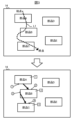
- FIG. 1 is a diagram showing a first example of a selection operation for drawing a linear trajectory input to the drawing support device according to the first embodiment, and a parent-child relationship set by the selection operation
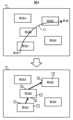
- FIG. 13 is a diagram showing a second example of a selection operation for drawing a linear trajectory input to the drawing support device according to the first embodiment, and a parent-child relationship set by the selection operation
- FIG. 1 is a block diagram showing a configuration of a drawing support device according to a first embodiment
- FIG. 1 is a diagram showing an example of a plurality of parts displayed in the drawing support device according to the first embodiment
- FIG. 1 is a diagram showing a first example of a selection operation for drawing a linear trajectory input to the drawing support device according to the first embodiment, and a parent-child relationship set by
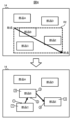
- FIG. 1 shows a first example of a selection operation for drawing a rectangular area input to the drawing support device according to the first embodiment, and a parent-child relationship set by the selection operation
- FIG. 13 shows a second example of a selection operation for drawing a rectangular area input to the drawing support device according to the first embodiment, and a parent-child relationship set by the selection operation
- FIG. 13 is a diagram showing an example of a parent-child relationship that is set by a selection operation that draws a linear trajectory in a case where the shapes of a plurality of parts displayed on the drawing support device according to the first embodiment are other than rectangular
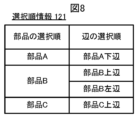
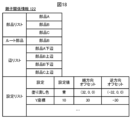
- FIG. 1 is a diagram showing an example of selection order information generated in the drawing support device according to the first embodiment
- FIG. 1 is a diagram showing an example of parent-child relationship information generated in the drawing support device according to the first embodiment
- FIG. 13 is a diagram showing an example in which settings are applied to a plurality of parts for which a parent-child relationship is set in the drawing support device according to the first embodiment
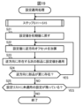
- 1 is a flowchart showing a flow of a setting application process executed by the drawing support device according to the first embodiment
- FIG. 13 is a diagram showing an example of a parent-child relationship set in the drawing support device according to the second embodiment
- FIG. 13 is a diagram showing an example of changing an edge for which a parent-child relationship is set in the drawing support device according to the third embodiment
- FIG. 13 is a diagram showing an example of changing a part for which a parent-child relationship is set in the drawing support device according to the fourth embodiment;
- FIG. 13 is a diagram showing an example of changing a part for which a parent-child relationship is set in the drawing support device according to the fifth embodiment;
- FIG. 23 is a diagram showing an example in which a parent-child relationship set between parts is reversed in the drawing support device according to the sixth embodiment;
- FIG. 23 is a diagram showing an example of parent-child relationship information generated in the drawing support device according to the sixth embodiment;
- 13 is a flowchart showing the flow of a setting application process executed by the drawing support device according to the sixth embodiment.
- (Embodiment 1) 1 shows a configuration of a drawing support device 10 according to embodiment 1.
- the drawing support device 10 is a device in which drawing software is installed, and has a function of supporting a user's operations related to drawing.
- the drawing software is screen design software for an HMI (Human Machine Interface) that is used to design the appearance and internal behavior of the screen in the HMI.
- the drawing software is GUI application software that has the function of aligning and editing multiple parts arranged on the screen.
- the drawing software is software for drawing the display screen that is displayed on a programmable display device that displays the status of devices such as a programmable logic controller (PLC) or a sensor and accepts operations for the device.
- PLC programmable logic controller
- the drawing support device 10 is a terminal device operated by a user.
- the drawing support device 10 may be any device, such as a personal computer, a tablet terminal, or a smartphone, as long as it is a terminal device that can be operated by a user.
- the drawing support device 10 includes a control unit 11, a storage unit 12, an operation unit 13, a display unit 14, and a communication unit 15.
- the control unit 11 is equipped with a CPU (Central Processing Unit).
- the CPU is also called a central processing unit, central arithmetic unit, processor, microprocessor, microcomputer, etc., and functions as a processing unit that executes processes and calculations related to the control of the drawing support device 10.
- the CPU reads and operates the programs and data stored in the memory unit 12, and provides overall control of the drawing support device 10.
- the storage unit 12 includes a ROM (Read Only Memory), a RAM (Random Access Memory), a flash memory, etc.
- the storage unit 12 stores programs and data used by the control unit 11 to perform various processes.
- the storage unit 12 also stores data generated or acquired by the control unit 11 performing various processes.
- the storage unit 12 stores selection order information 121 and parent-child relationship information 122.
- the operation unit 13 is equipped with input devices such as a touch panel, a touch pad, a keyboard, a mouse, and physical buttons, and accepts operational input from the user. By operating the operation unit 13, the user can input various instructions to the drawing support device 10.
- the display unit 14 includes a display device such as a liquid crystal panel or an organic EL (Electro-Luminescence) panel.
- the display unit 14 is driven by a display drive circuit (not shown) to display various images.
- the communication unit 15 has a communication interface for communicating with devices external to the drawing support device 10.
- the communication unit 15 communicates with devices external to the drawing support device 10 in accordance with well-known communication standards such as LAN (Local Area Network) and USB (Universal Serial Bus).
- LAN Local Area Network
- USB Universal Serial Bus
- the control unit 11 functionally comprises an operation reception unit 111, which is an example of an operation reception means, a selection order determination unit 112, which is an example of a selection order determination means, a parent-child relationship setting unit 113, which is an example of a parent-child relationship setting means, and a setting application unit 114, which is an example of a setting application means.
- Each of these functions is realized by software, firmware, or a combination of software and firmware.
- the software and firmware are written as programs and stored in the memory unit 12.
- the control unit 11 then executes the programs stored in the memory unit 12 to realize each function.
- the operation reception unit 111 receives a selection operation for selecting a plurality of parts displayed on the screen.
- a part is an element included as an image on the display screen. More specifically, a part corresponds to a GUI component, a figure, etc. used for operating the HMI. Examples of parts include a desk arranged in a room, a concrete object such as a part constituting a product, a switch, a meter, etc., a specific function, and text, a figure, etc.
- FIG. 2 shows, as an example, a case where five parts A to E are displayed on the screen of the display unit 14.
- the user operates the operation unit 13 to input a selection operation to select multiple parts that the user wishes to group from among the five parts A to E displayed on the screen in this way.
- the operation reception unit 111 accepts an operation to select multiple parts from among the five parts A to E displayed on the screen in accordance with the selection operation input by the user.
- each of parts A to E is shown as a rectangle of the same size.
- each of the multiple parts displayed on the screen is not limited to being rectangular, and may be other shapes including other polygonal shapes, circles, ellipses, etc., and may be different sizes.
- the operation reception unit 111 receives a selection operation to select three parts A to C from the five parts A to E shown in FIG. 2.
- the operation reception unit 111 can receive a selection operation using two selection methods: (1) a method of inputting a linear trajectory at a position on the screen that crosses multiple parts, and (2) a method of inputting a rectangular area at a position on the screen that overlaps multiple parts.
- the operation reception unit 111 receives a selection operation for inputting a linear trajectory at a position on the screen that crosses multiple components.
- the linear trajectory is a linear trajectory drawn by the user on the screen, and may be a straight trajectory or a curved trajectory.
- the user operates the operation unit 13 to input a selection operation that draws a straight or curved linear trajectory on the screen so that at least a portion of the trajectory overlaps with the multiple parts to be selected. Specifically, the user moves a finger, a touch pen, etc., on the touch panel, or drags a mouse, a tracker, etc., so as to trace the multiple parts to be selected.
- the operation reception unit 111 receives the selection operation thus input.
- the user inputs a selection operation to draw a linear trajectory L1 at a position that crosses three of the five parts A to E, parts A to C, the three parts A to C are selected.
- the linear trajectory L1 runs from the start point above part A to the end point below part C, crossing part A from its top edge to its bottom edge, crossing part B from its top edge to its left edge, and crossing part C from its top edge to its right edge.
- the user inputs a selection operation to draw a linear trajectory L2 at a position that crosses three of the five parts A to E, parts C, B, and D, the three parts B to D are selected.
- the linear trajectory L2 runs from the starting point below part C to the end point on the right side of part D, crossing part C from its bottom edge to its top edge, crossing part B from its bottom edge to its top edge, and crossing part D from its left edge to its right edge.
- the operation reception unit 111 receives a selection operation for inputting a rectangular area at a position on the screen that overlaps with multiple components.
- the rectangular area is a rectangular area created by the user on the screen.
- the user operates the operation unit 13 to input a selection operation that draws a two-dimensional area on the screen so that it at least partially overlaps the multiple parts to be selected. Specifically, the user moves a finger, a touch pen, etc. on the touch panel from a start point to an end point so as to cover the multiple parts to be selected, or drags a cursor displayed on the screen.
- the operation reception unit 111 receives the selection operation input in this manner.
- Rectangular region R1 covers the area from the starting point in the upper left of part A to the end point in the lower right of part C, with the starting point and end point being opposite vertices.
- Rectangular region R2 covers the range from the start point at the upper left of part B to the end point at the lower right of part E, with the start point and end point being opposite vertices.
- the selection order determination unit 112 determines the selection order of the multiple selected parts based on the selection operation accepted by the operation acceptance unit 111 and the positional relationship of the multiple selected parts on the screen. Specifically, the selection order determination unit 112 determines the selection order of the multiple parts based on the selection method of the multiple parts in the accepted selection operation and the positional relationship of the multiple parts on the screen.
- the selection order determination unit 112 determines the selection order of the parts, starting with the parts that are crossed by the linear trajectory, among the multiple selected parts.
- the selection order determination unit 112 determines the order of parts A, B, and C, which is the order in which the linear trajectory L1 crosses, as the selection order of parts.
- the selection order of parts determined in this way is shown by numbers in boxes in the lower part of Fig. 3.
- the selection order determination unit 112 determines the order of parts C, B, and D, which is the order in which the linear trajectory L2 crosses, as the selection order of parts.
- the selection order of parts determined in this way is shown by numbers in boxes in the lower part of FIG. 4.
- the selection order determination unit 112 determines the selection order of multiple parts that are located at positions that overlap with the linear trajectory in the order in which the linear trajectory input as the selection operation crosses them.
- the selection order determination unit 112 determines the selection order of the multiple selected parts, starting with the part closest to the start point of the rectangular area.
- the selection order determination unit 112 determines the selection order of parts starting from the part with the smallest absolute value of the difference in vertical coordinate from the start point of the rectangular area.
- the selection order determination unit 112 determines the selection order of the part with the smallest absolute value of the difference in horizontal coordinate from the start point of the rectangular area to be earlier among the multiple parts.
- the selection order determination unit 112 determines the selection order of the part that is present at the back of the multiple parts to be earlier among the multiple parts.
- the selection order determination unit 112 determines the selection order of parts starting from the part with the smallest absolute value of the difference in its horizontal coordinate from the start point of the rectangular area.
- the selection order determination unit 112 determines the selection order of the part with the smallest absolute value of the difference in its vertical coordinate from the start point of the rectangular area to be earlier among the multiple parts.
- the selection order determination unit 112 determines the selection order of the part that is present at the back of the multiple parts to be earlier among the multiple parts.
- the selection order determination unit 112 determines the order of parts to be the selection order of parts A, B, and C, which are closest to the start point of rectangular area R1 in a comparison of their vertical coordinates.
- the selection order of parts determined in this way is shown by numbers in squares in the lower part of Fig. 5.
- the selection order determination unit 112 determines the order of parts to be selected as follows: part C, part B, and part E, which are closest to the start point of rectangular region R1 in a comparison of their horizontal coordinates.
- the selection order of parts determined in this way is shown by numbers in squares in the lower part of FIG. 6.
- the selection order determination unit 112 determines the selection order of multiple parts that overlap the rectangular area based on the start and end points of the rectangular area input as a selection operation and the aspect ratio of the rectangular area.
- the selection order determination unit 112 further determines the selection order of the sides of the multiple parts whose selection orders have been determined.
- the selection order determination unit 112 determines the selection order of the sides from among the four sides of a rectangle circumscribing each of the parts whose selection orders have been determined, in accordance with a predetermined criterion.
- the selection order determination unit 112 When the operation receiving unit 111 receives a selection operation for inputting a linear trajectory, the selection order determination unit 112 first determines the order of one side of a rectangle circumscribing the first part in the selection order among the multiple selected parts, which last intersects with the linear trajectory. Next, the selection order determination unit 112 determines the order of two sides of a circumscribing rectangle that first and last intersect with the linear trajectory, starting from second, for at least one part other than the first and last parts in the selection order among the multiple selected parts. Furthermore, the selection order determination unit 112 finally determines the order of one side of a rectangle circumscribing the last part in the selection order, which first intersects with the linear trajectory.
- the selection order determination unit 112 determines the order of edge selection to be the bottom edge of part A, the top edge of part B, the left edge of part B, and the top edge of part C.
- the edge selection order determined in this way is shown by circled numbers in the lower part of Fig. 3.
- the selection order determination unit 112 determines the order of edge selection to be the top edge of part C, the bottom edge of part B, the top edge of part B, and the left edge of part D.
- the edge selection order determined in this manner is shown by circled numbers in the lower part of FIG. 4.
- the selection order determination unit 112 selects, for each pair of two parts that are consecutively selected from among the multiple selected parts, a pair of one side of a rectangle circumscribing the earlier selected part and one side of a rectangle circumscribing the later selected part, with the distance between the sides being the closest. Then, the selection order determination unit 112 determines the order of selection of the sides for the two sides of the pair selected from each pair of two parts that are consecutively selected, in the order of the side of the earlier selected part and the side of the later selected part.
- the distance between the sides is, for example, the Euclidean distance between the midpoint of one side and the midpoint of the other side.
- the selection order determination unit 112 selects one of the multiple pairs with equal distances according to a predetermined rule. Specifically, when the rectangular area has a vertically long shape, the selection unit 112 selects, from the multiple pairs with equal distances, the pair with the smallest absolute value of the difference in vertical coordinates between the midpoint of the side of the component that was selected earlier and the start point of the rectangular area.
- the selection order determination unit 112 selects, from the multiple pairs, the pair with the smallest absolute value of the difference in horizontal coordinates between the midpoint of the side of the component that was selected earlier and the start point of the rectangular area.
- the selection unit 112 selects, from the multiple pairs with equal distances, the pair with the smallest absolute value of the difference in horizontal coordinates between the midpoint of the side of the component that was selected earlier and the start point of the rectangular area. If there are still multiple pairs with equal distances, the selection order determination unit 112 selects the pair with the smallest absolute difference in vertical coordinate between the midpoint of the side of the component selected earlier and the start point of the rectangular area.
- the selection order determination unit 112 determines the order of edge selection to be the bottom edge of part A, the top edge of part B, the bottom edge of part B, and the top edge of part C.
- the edge selection order determined in this way is shown by circled numbers in the lower part of Fig. 5.
- the selection order determination unit 112 determines the order of edge selection to be the top edge of component C, the bottom edge of component B, the right edge of component B, and the left edge of component E.
- the edge selection order determined in this manner is shown by circled numbers in the lower part of FIG. 6.
- the rectangle circumscribing the part coincides with the sides that form the periphery of the part. Therefore, expressions such as “bottom side of part A” and “top side of part B” in the above and following descriptions have the same meaning as “bottom side of the rectangle circumscribing part A” and “top side of the rectangle circumscribing part B".
- the shapes of multiple parts displayed on the screen may be other than rectangular.
- the rectangle circumscribing the part is located outside the periphery of the part, as shown by the dashed line in the lower part of Fig. 7.
- the selection order determination unit 112 determines the selection order of the sides of the virtual rectangle that is located outside the periphery of such a part.
- the selection order determination unit 112 stores the determined selection order in selection order information 121.
- the selection order information 121 is data that temporarily holds the selection order determined by the selection order determination unit 112.
- selection order information 121 defines the selection order of parts and the selection order of edges.
- selection order information 121 holds the selection order of parts in the order of part A, part B, and part C, and holds the selection order of edges in the order of the bottom edge of part A, the top edge of part B, the left edge of part B, and the top edge of part C.
- the parent-child relationship setting unit 113 sets a parent-child relationship between the multiple selected parts based on the selection order determined by the selection order determination unit 112.
- the parent-child relationship means a subordinate relationship set between multiple parts. In general grouping, the relationships between multiple parts are equal, but in the parent-child relationship, a subordinate relationship is set between multiple parts.
- the parent-child relationship setting unit 113 sets a parent-child relationship for the multiple selected parts, with the part selected earlier as the parent part and the part selected later as the child part. At this time, if the multiple selected parts are only two parts, the parent-child relationship setting unit 113 sets a parent-child relationship for a combination of two selected parts, with the part selected earlier as the parent part and the part selected later as the child part.
- the parent-child relationship setting unit 113 sets a parent-child relationship for each of a multiple combinations, each of which is a combination of two parts of the at least three selected parts whose selection order determined by the selection order determination unit 112 is consecutive, with the part selected earlier as the parent part and the part selected later as the child part.
- the parent-child relationship setting unit 113 first sets a parent-child relationship for the combination of parts A and B, with part A being the parent part and part B being the child part. Then, the parent-child relationship setting unit 113 secondly sets a parent-child relationship for the combination of parts B and C, with part B being the parent part and part C being the child part.
- the parent-child relationship setting unit 113 first sets a parent-child relationship for the combination of parts C and B, with part C as the parent part and part B as the child part. Then, the parent-child relationship setting unit 113 secondly sets a parent-child relationship for the combination of parts B and D, with part B as the parent part and part D as the child part.
- the parent-child relationship setting unit 113 first sets a parent-child relationship for the combination of parts C and B, with part C as the parent part and part B as the child part. Then, the parent-child relationship setting unit 113 secondly sets a parent-child relationship for the combination of parts B and E, with part B as the parent part and part E as the child part.
- the parent-child relationship setting unit 113 further sets the parent-child relationship of sides.
- the parent-child relationship of sides corresponds to the corresponding relationship between the sides in the arrangement of the two components for which the parent-child relationship has been set.
- the parent component and the child component are arranged in the layout of a plurality of components including them so that the sides for which the parent-child relationship has been set face each other or so that the sides for which the parent-child relationship has been set are connected to each other.
- each part represents a desk to be placed in a room
- the parts with parent-child relationships are arranged so that the edges with parent-child relationships face each other.
- each part represents an individual part for assembling a product
- the parts with parent-child relationships are combined so that the edges with parent-child relationships are connected.
- the parent-child relationship setting unit 113 sets a parent-child relationship between one side of a rectangle circumscribing the parent component and one side of a rectangle circumscribing the child component. More specifically, based on the selection order of the edges determined by the selection order determination unit 112, for a combination of two edges where the selection order is continuous and the edge selected earlier is on the parent component side and the edge selected later is on the child component side, the parent-child relationship setting unit 113 sets a parent-child relationship in which the edge selected earlier is the parent and the edge selected later is the child.
- the parent-child relationship setting unit 113 sets a parent-child relationship between one side of a rectangle circumscribing the parent part that last intersects with the linear trajectory and one side of a rectangle circumscribing the child part that first intersects with the linear trajectory for each combination of two parts for which a parent-child relationship has been set.
- the parent-child relationship setting unit 113 first sets a parent-child relationship of edges in which the bottom edge of part A is the parent and the top edge of part B is the child. Then, the parent-child relationship setting unit 113 secondly sets a parent-child relationship of edges in which the left edge of part B is the parent and the top edge of part C is the child.
- the parent-child relationship setting unit 113 first sets a parent-child relationship of edges in which the top edge of part C is the parent and the bottom edge of part B is the child. Then, the parent-child relationship setting unit 113 secondly sets a parent-child relationship of edges in which the top edge of part B is the parent and the left edge of part D is the child.
- the parent-child relationship setting unit 113 sets the parent-child relationship for each combination of two parts for which a parent-child relationship has been set, for the combination of one side of a rectangle circumscribing the parent part and one side of a rectangle circumscribing the child part, with the side distance between them being the shortest.
- the parent-child relationship setting unit 113 first sets a parent-child relationship of edges in which the bottom edge of part A is the parent and the top edge of part B is the child. Then, the parent-child relationship setting unit 113 secondly sets a parent-child relationship of edges in which the bottom edge of part B is the parent and the top edge of part C is the child.
- the parent-child relationship setting unit 113 first sets a parent-child relationship of edges in which the top edge of part C is the parent and the bottom edge of part B is the child. Then, the parent-child relationship setting unit 113 secondly sets a parent-child relationship of edges in which the right edge of part B is the parent and the left edge of part E is the child.
- the parent-child relationship that is set when multiple parts are selected as in the upper rows of Figures 3 to 7 is shown by an arrow pointing from the parent part to the child part.
- the parent-child relationship setting unit 113 displays an arrow pointing from the parent part to the child part on the screen as a symbol indicating the parent-child relationship of the parts.
- the parent-child relationship setting unit 113 displays the arrow pointing from the parent part to the child part so as to connect the midpoints of the pair of sides for which the parent-child relationship is set.
- the arrow is one example of a symbol indicating a parent-child relationship, and a symbol other than an arrow may be used to indicate the parent-child relationship.
- the parent-child relationship setting unit 113 executes the process of setting a parent-child relationship for two parts that are consecutively selected, for each pair of two parts that are consecutively selected and are included in the three or more parts selected by the selection operation. Furthermore, the parent-child relationship setting unit 113 also sets a parent-child relationship for the edges of the parts for which a parent-child relationship has been set.
- the group of parts for which a parent-child relationship has been set by the parent-child relationship setting unit 113 will be referred to as "parent-child relationship set parts.”
- the parent-child relationship setting unit 113 stores information indicating the set parent-child relationships in parent-child relationship information 122.
- the parent-child relationship information 122 is data that holds the parent-child relationships set between parts and edges by the parent-child relationship setting unit 113.
- parent-child relationship information 122 is not stored separately for each component, but is stored collectively in the parent-child relationship setting component.
- the settings stored in parent-child relationship information 122 are applied recursively from parent components to child components.
- parent-child relationship information 122 has each of the following information: a parts list, a root part, an edge list, and a setting list.
- the parts list has information on multiple parts held in selection order information 121 in the same selection order as selection order information 121.
- the edge list has information on multiple edges held in selection order information 121 in the same selection order as selection order information 121.
- parent-child relationship information 122 holds references to parts and edges for which parent-child relationships are set, according to the selection order determined by selection order determination unit 112.
- a root part is a part that does not have a parent part among multiple parts for which a parent-child relationship has been established, and corresponds to the highest-ranking part in the parent-child relationship. For example, if the selection order of parts determined by the selection order determination unit 112 is part A, part B, and part C, then the root part is part A.
- the parent-child relationship setting unit 113 sets the highest-ranking part among multiple parts for which a parent-child relationship has been established as the root part.
- the setting list defines the settings that are applied recursively to components that have parent-child relationships. Specifically, the setting list holds information on the settings, setting values, and forward offsets.
- the settings are information related to the placement, alignment, and attributes of parts.
- the placement of parts is, for example, the X and Y coordinates of the parts on the screen.
- the alignment of parts is, for example, the width of the parts on the screen, the height of the parts, and the spacing between adjacent parts.
- the attributes of parts are, for example, the fill color of the parts, the line width of the parts, a character string related to the parts, a memory address, and the like.
- the placement, alignment, and attributes of parts are collectively referred to as "settings.”
- the settings list holds information such as the fill color of the parts and the Y coordinate of the parts as settings.
- the setting value is the specific value when applying the setting to the root part.
- the forward offset is a value added to the setting value of the parent part to derive the setting value of the child part.
- the forward offset is used to align multiple parts at a fixed interval or to set consecutive values for multiple parts.
- the setting list holds RGB (Red, Green, Blue) brightness values as the forward offset of the fill color, and holds a value equivalent to the difference in the Y coordinate between the parent part and the child part as the forward offset of the Y coordinate.
- the user can input the setting value and forward offset of each setting in the setting list by operating the operation unit 13.
- the setting application unit 114 applies settings based on the settings of the parent component to the settings of the child components for each of a plurality of combinations for which a parent-child relationship has been set by the parent-child relationship setting unit 113.
- the user operates the operation unit 13 to input an operation to apply the settings from the operation screen of the parent-child relationship information 122.
- the setting application unit 114 recursively applies the settings defined in the setting list of the parent-child relationship information 122 to the group of components for which a parent-child relationship has been set.
- the setting application unit 114 sets the setting value of the child part to a value obtained by adding an offset to the setting value of the parent part for each of the multiple combinations in which a parent-child relationship is established.
- the setting application unit 114 applies the setting value of each setting defined in the setting list to the root part.
- the setting application unit 114 applies a value obtained by adding a forward offset to the setting value of each setting applied to the root part to a child part having the root part as its parent.
- the setting application unit 114 applies a value obtained by further adding a forward offset to the setting value of each setting to a child part having the above-mentioned child part to which the setting has been applied as its parent.
- the setting application unit 114 recursively applies the settings to each combination of two parts in which a parent-child relationship is established.
- FIG. 10 an example is shown in which settings are applied to multiple parts by the setting application unit 114.
- the setting application unit 114 applies the settings in the setting list shown in FIG. 9, the settings are applied to parts A to C as shown in the lower part of FIG. 10.
- the setting application unit 114 sets the fill color of part A, which is the root part, to blue, and sets the Y coordinate of part A to 10.
- the setting application unit 114 sets the fill color of part B, which is a child of part A, to blue, and sets the Y coordinate of part B to 40, which is the Y coordinate of part A plus 30.
- the setting application unit 114 sets the fill color of part C, which is a child of part B, to blue, and sets the Y coordinate of part C to 70, which is the Y coordinate of part B plus 30. This makes it possible to change the settings of multiple parts according to certain rules with fewer steps.
- the parent-child relationship information process shown in Fig. 11 and the setting application process shown in Fig. 12 are examples of a drawing support method.
- the parent-child relationship setting process shown in FIG. 11 begins when a user starts drawing software pre-installed in the drawing support device 10 and displays multiple parts on the screen of the display unit 14.
- the control unit 11 When the parent-child relationship setting process is started, the control unit 11 functions as the operation reception unit 111 and receives a selection operation for selecting multiple parts to be selected from among the multiple parts displayed on the screen (step S1). Specifically, the control unit 11 receives a selection operation for inputting linear trajectories L1, L2 at positions that intersect the multiple parts to be selected as a first selection method, as shown in FIG. 3, FIG. 4, or FIG. 7. Alternatively, the control unit 11 receives a selection operation for inputting rectangular regions R1, R2 at positions that overlap the multiple parts to be selected as a second selection method, as shown in FIG. 5 or FIG. 6.
- control unit 11 When the control unit 11 receives the selection operation, it functions as the selection order determination unit 112 and determines the selection order of the multiple selected parts (step S2). Specifically, the control unit 11 determines the selection order of the multiple selected parts in the order that the input linear trajectory crosses them, or based on the start point and aspect ratio of the input rectangular area.
- control unit 11 determines the selection order of the sides (step S3). Specifically, the control unit 11 determines the selection order of the sides from among the four sides of a rectangle circumscribing each part whose selection order has been determined, in accordance with a predetermined criterion.
- control unit 11 updates the selection order information 121 (step S4). More specifically, the control unit 11 stores the determined selection order of the parts and edges in the selection order information 121.
- the control unit 11 After updating the selection order information 121, the control unit 11 functions as a parent-child relationship setting unit 113 and sets the parent-child relationships of the parts (step S5). Specifically, for each combination of two parts that are consecutive in the selection order determined in step S2 among the multiple parts selected in step S1, the control unit 11 sets a parent-child relationship in which the part selected earlier in the selection order is the parent part and the part selected later in the selection order is the child part.
- the control unit 11 After setting the parent-child relationship of the parts, the control unit 11 sets the parent-child relationship of the sides (step S6). Specifically, for each combination of two parts for which a parent-child relationship has been set, the control unit 11 sets a parent-child relationship in which one side of a rectangle circumscribing the parent part is the parent, and one side of a rectangle circumscribing the child part is the child.
- the control unit 11 updates the parent-child relationship information 122 (step S7). More specifically, the control unit 11 updates the parts list, edge list, and information on the root part in the parent-child relationship information 122 based on the parent-child relationships of the parts and edges that have been set.
- control unit 11 After updating the parent-child relationship information 122, the control unit 11 releases the selection order of the parts and edges from memory (step S8). This completes the parent-child relationship setting process shown in FIG. 11.
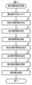
- the setting application process shown in FIG. 12 starts when an operation is input to apply the settings in the setting list to multiple components for which parent-child relationships have been set by the parent-child relationship setting process shown in FIG. 11.
- the control unit 11 functions as the setting application unit 114.
- the control unit 11 acquires one setting from the setting list in the parent-child relationship information 122 (step S11).
- the control unit 11 acquires one setting from among the fill color, Y coordinate, etc., defined in the setting list.
- control unit 11 When one setting is acquired, the control unit 11 applies the setting value of the acquired setting to the root part (step S12). In the example of FIG. 9, when a fill color setting is acquired, the control unit 11 sets the fill color of part A, which is the root part, to the setting value "blue.”
- control unit 11 adds the forward offset defined in the acquired setting to the setting value applied to the root part (step S13).
- the control unit 11 applies the setting value after the forward offset has been added to the next part in the forward direction in the parts list (step S14).
- parts B and C exist in the forward direction of part A, which is the root part. Therefore, the control unit 11 applies the setting value after the forward offset has been added to part B, which is the next part after the root part.
- the control unit 11 determines whether there are any more parts in the forward direction in the parts list (step S15). If there are more parts in the forward direction (step S15; YES), the control unit 11 returns the process to step S13. The control unit 11 then further adds the forward offset to the current setting value, and applies the added setting value to the next part in the forward direction in the parts list. In this way, the control unit 11 applies the setting value to which the forward offset has been added in sequence to each part in the forward direction in the parts list.
- step S15 determines whether or not there are any unapplied settings remaining in the setting list (step S16). If there are any unapplied settings remaining (step S16; YES), the control unit 11 returns the process to step S11 and acquires one unapplied setting from the setting list. The control unit 11 then executes the processes of steps S12 to S15 and applies the setting values of the acquired setting to each of the multiple parts with which a parent-child relationship has been established. In this way, the control unit 11 applies the setting values of each setting included in the setting list to each of the multiple parts with which a parent-child relationship has been established.
- step S16 If there are no unapplied settings remaining (step S16; NO), the control unit 11 ends the setting application process shown in FIG. 12.
- the drawing support device 10 determines the selection order of multiple parts based on the selection operation of selecting multiple parts displayed on the screen and the positional relationship of the multiple parts, and sets a parent-child relationship for the multiple parts in which the part selected earlier in the selection order is the parent part and the part selected later in the selection order is the child part.
- a parent-child relationship can be set between multiple parts by an intuitive and easy operation of inputting a linear trajectory or a rectangular area. As a result, the effort required to set multiple parts can be reduced.
- a multi-stage parent-child relationship can be set with a single operation, so the user does not need to repeat the process of selecting parts one by one and setting the parent-child relationship. Therefore, the user's effort can be significantly reduced when there are a large number of parts.
- the drawing support device 10 applies settings based on the settings of the parent component to the settings of the child components. This allows settings and changes to be made recursively all at once for multiple components that have parent-child relationships, reducing the amount of work required to set multiple components. In particular, this significantly reduces the amount of work required by the user when there are a large number of components.
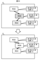
- the drawing support device 10 according to the second embodiment further sets a parent-child relationship between a group of components for which a parent-child relationship has already been set and another component.
- the drawing support device 10 according to the second embodiment can set multiple parent-child relationships.
- the upper part of Figure 13 shows an example in which parts A and B, which are a group of parts for which a parent-child relationship has already been set by the parent-child relationship setting unit 113, and another part C are displayed on the screen of the display unit 14.
- the user inputs a selection operation to draw a rectangular area R3 that stretches from the lower right of part C to the upper left of part A, as an example of a new selection operation to select parts A to C.
- the new selection operation is not limited to an operation to draw a rectangular area R3, but may also be an operation to draw a linear trajectory.
- the group of parts A and B is treated equivalent to a single part called parent-child relationship setting part AB.
- the operation reception unit 111 receives the new selection operation.
- the selection order determination unit 112 determines the selection order of the parent-child relationship setting component AB and the component C based on the new selection operation received by the operation reception unit 111. In the example of FIG. 13, the selection order determination unit 112 determines the selection order of the component C closest to the start point of the rectangular region R3 to be first, and the selection order of the parent-child relationship setting component AB to be second.
- the parent-child relationship setting unit 113 sets a new parent-child relationship between parent-child relationship setting component AB and component C based on the selection order determined by the selection order determination unit 112.
- the parent-child relationship setting unit 113 sets a parent-child relationship in which component C is the parent component and parent-child relationship setting component AB is the child component. This generates parent-child relationship setting component ABC, which has parent-child relationship setting component AB and component C in its component list.
- the parent-child relationship setting unit 113 also sets a parent-child relationship between one side of a rectangle circumscribing the parent-child relationship setting component AB and one side of a rectangle circumscribing the component C.
- the rectangle circumscribing the parent-child relationship setting component AB corresponds to the smallest rectangle that contains the components A and B, as shown by the thick solid line in the lower part of FIG. 13.
- the setting application unit 114 applies the setting based on the setting of the parent part C to the setting of the child part AB. Specifically, as in the first embodiment, the setting application unit 114 sets the setting value of the parent-child relationship setting part AB to a value obtained by adding a forward offset to the setting value of part C. At that time, the setting application unit 114 treats the parent-child relationship setting part AB as a single part having a rectangular shape circumscribing the parent-child relationship setting part AB, and sets the parent-child relationship setting part AB.
- a group of parts for which a parent-child relationship has already been set can be treated as a single part, and a parent-child relationship can be set between it and another part.
- a parent-child relationship setting part ABC is generated that has a parent-child relationship setting part AB in its parts list
- the parent-child relationship setting part AB can be set from the settings of the parent-child relationship setting part ABC.
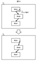
- the drawing support device 10 changes at least one of a pair of edges for which a parent-child relationship has already been set to another edge in the same part in response to a user operation.
- FIG. 14 shows an example in which parts A to C, which are a group of parts for which parent-child relationships have already been set by the parent-child relationship setting unit 113, are displayed on the screen of the display unit 14.
- a parent-child relationship of an edge is set between the bottom edge of part A and the top edge of part B
- a parent-child relationship of an edge is set between the bottom edge of part B and the top edge of part C.
- the operation reception unit 111 accepts a change operation to change one side of a pair of sides for which a parent-child relationship has been set by the parent-child relationship setting unit 113 to another side in the same part.
- the user can use a drag operation to move one end of an arrow, which is an example of a symbol indicating a parent-child relationship and is displayed on the screen, to another side in the same part. This allows the user to input a change operation to change one side of a pair of sides for which a parent-child relationship has already been set to another side.
- the parent-child relationship setting unit 113 changes the parent-child relationship set between a pair of edges to a parent-child relationship between another edge in the same component and the other edge of the pair of edges.
- the parent-child relationship setting unit 113 changes the parent-child relationship set for the pair of edges between parts A and B to a parent-child relationship between the right edge of part A and the top edge of part B, which is the other edge of the pair of edges.
- the parent-child relationship of an edge that has already been set between a parent component and a child component can be changed to a parent-child relationship between the same or a different edge of the parent component and the same or a different edge of the child component.
- This makes it possible to change the parent-child relationship of an edge with a simple operation, without having to redo the parent-child relationship settings.
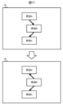
- the drawing support device 10 changes at least one of a pair of parts for which a parent-child relationship has already been established to a different part in response to a user operation.
- FIG. 15 shows an example in which parts A and B, which are a group of parts for which a parent-child relationship has already been set by the parent-child relationship setting unit 113, and part C for which a parent-child relationship has not yet been set, are displayed on the screen of the display unit 14.
- a parent-child relationship of sides is set between the bottom side of part A and the top side of part B.
- the operation receiving unit 111 receives a change operation to change one of a pair of parts for which a parent-child relationship has been set by the parent-child relationship setting unit 113 to a different part from the pair of parts displayed on the screen.
- the user can use a drag operation to move one end of an arrow, which is an example of a symbol indicating a parent-child relationship displayed on the screen, to another part for which a parent-child relationship has not been set. This allows the user to input a change operation to change one of a pair of parts for which a parent-child relationship has already been set to a different part.
- the parent-child relationship setting unit 113 changes the parent-child relationship that has been set between a pair of parts for which a parent-child relationship has already been set to a parent-child relationship between the other part of the pair and another part for which a parent-child relationship has not yet been set.
- the parent-child relationship setting unit 113 changes the parent-child relationship set between parts A and B to a parent-child relationship in which part A, the other of the pair, is the parent part and part C is the child part. Then, the parent-child relationship setting unit 113 changes the parent-child relationship of the side set between parts A and B to a parent-child relationship in which the bottom side of part A is the parent and the left side of part C is the child.
- the parent-child relationship setting unit 113 further sets a parent-child relationship between the other part and one of the pair of parts. Specifically, as shown in the lower part of FIG. 15, the parent-child relationship setting unit 113 sets a parent-child relationship in which part C, which is the other part, is the parent part and part B, which is one of the pair of parts, is the child part. Then, the parent-child relationship setting unit 113 sets a parent-child relationship in which the right side of part C is the parent and the bottom side of part B is the child.
- the parent-child relationship setting unit 113 sets the parent in the parent-child relationship of the edge between parts C and B to the opposite side, the right side of part C.
- the drawing support device 10 can reselect components of a group of parts for which a parent-child relationship has been set by the parent-child relationship setting unit 113 after the setting application unit 114 applies the settings to the group of parts.
- FIG. 16 shows an example in which parts A to C, which are a group of parts for which parent-child relationships have already been set by the parent-child relationship setting unit 113, and part D, for which a parent-child relationship has not yet been set, are displayed on the screen of the display unit 14.
- the setting application unit 114 has set the fill color of part A, which is the root part, for parts A to C to (0, 0, 0), and the forward offset to (64, 0, 0).
- the user can input a reselection operation to reselect the components of the group of parts A to C. This allows the user to change the components of the group of parts for which a parent-child relationship has already been set and the settings have been applied, or the selection order of those components.
- the user selects "Reselect part” - "Select rectangle" from the operation screen of parent-child relationship setting parts A to C. Then, as shown in the upper part of Figure 16, the user inputs a reselection operation to reselect parts A to D as components of the part group of parts A to C. For example, the user inputs a selection operation to draw a rectangular area R4 that stretches from the lower right of part D to the upper left of part A. Note that the reselection operation is not limited to the operation of drawing a rectangular area R4, and can also be the operation of drawing a linear trajectory.
- the operation reception unit 111 accepts the reselection operation.
- the selection order determination unit 112 determines the selection order of parts A to D based on the reselection operation accepted by the operation reception unit 111. In the example of FIG. 16, the selection order determination unit 112 determines the selection order as follows, in order of proximity to the start point of rectangular region R4: part D, part C, part B, and part A.
- the parent-child relationship setting unit 113 sets parent-child relationships between parts D and C, between parts C and B, and between parts B and A, based on the selection order determined by the selection order determination unit 112. At this time, the parent-child relationship setting unit 113 sets part D, which is first in the selection order, as the root part. This generates parent-child relationship-set parts A to D, each of which has parts A to D in its parts list.
- the setting application unit 114 reapplies the settings that were applied to the group of parts A to C prior to the reselection operation to the group of parts A to D after the component parts have been reselected by the reselection operation. Specifically, as shown in the lower part of FIG. 16, the setting application unit 114 sets the fill color of part D, which is the root part, to (0, 0, 0). Then, the setting application unit 114 sets the fill colors of parts C, B, and A according to the forward offset setting values (64, 0, 0).
- the drawing support device 10 accepts the reselection of a component part of a group of parts for which a parent-child relationship has already been set, and reapplies the same settings as before the reselection operation to the group of parts after the component part has been reselected by the reselection operation.
- This allows the user to reselect the parts and edges for which a parent-child relationship is to be set with a simple operation, without the need to re-enter settings such as setting values and offsets.
- the drawing support device 10 reverses the parent-child relationships of multiple parts that have parent-child relationships set, either partway through or entirely.
- FIG. 17 shows an example in which parts A to C, which are a group of parts for which parent-child relationships have already been set by the parent-child relationship setting unit 113, are displayed on the screen of the display unit 14.
- a parent-child relationship of an edge is set between the bottom edge of part A and the top edge of part B
- a parent-child relationship of an edge is set between the bottom edge of part B and the top edge of part C.
- the operation reception unit 111 receives a reversal operation that reverses the parent-child relationship in at least one of the multiple combinations for which the parent-child relationship has been set by the parent-child relationship setting unit 113.
- the user can reverse the start and end points of an arrow, which is an example of a symbol indicating a parent-child relationship, displayed on the screen by dragging.
- the user can reverse an arrow extending from part A to part B, changing it to an arrow extending from part B to part A.
- the user can open the operation screen for parent-child relationship setting part ABC and change the root part of parent-child relationship setting part ABC from part A to part B, thereby reversing the parent-child relationship in the combination of parts A and B.
- the user can input a reversal operation that reverses the parent-child relationship in at least one combination for which a parent-child relationship has already been set.
- at least one combination for which the parent-child relationship is to be reversed must include a root part.
- the parent-child relationship setting unit 113 reverses the parent-child relationship in at least one of the multiple combinations for which a parent-child relationship has been set in response to a user operation. For example, when a reversal operation is received to reverse the parent-child relationship in a combination of part A, which is a parent part and root part, and part B, which is a child part, the parent-child relationship setting unit 113 changes the parent-child relationship in the combination of parts A and B to a parent-child relationship in which part B is the parent part and root part, and part A is the child part, as shown in the lower part of Figure 17.
- FIG. 18 shows an example of parent-child relationship information 122 when the parent-child relationship between parts A and B is reversed.
- the parts list remains unchanged from the original selection order of parts A, B, and C, whereas the root part has been changed to part B due to the reversal of the parent-child relationship between parts A and B.
- the parent-child relationship information 122 holds information on reverse offsets in addition to forward offsets in the setting list.
- the reverse offset is a second offset prepared separately from the forward offset, which is the first offset, and is used between parts whose parent-child relationships are reversed.
- the reverse offset is set to a value obtained by multiplying the value of the forward offset by -1.
- the reverse offset is not limited to this, and any value may be set independently of the forward offset.
- the forward offset is applied to a child part that is located below the parent part in the parts list, i.e., a child part whose selection order determined by the selection order determination unit 112 is after the parent part.
- the backward offset is applied to a child part that is located above the parent part in the parts list, i.e., a child part whose selection order determined by the selection order determination unit 112 is before the parent part.
- the setting application unit 114 applies settings based on the settings of the parent part to the settings of the child parts for each of the multiple combinations for which the parent-child relationships have been set by the parent-child relationship setting unit 113, based on the parent-child relationship information 122 that includes such reverse offsets.
- the setting application unit 114 sets the setting value of the child component to a value obtained by adding a forward offset to the setting value of the parent component for combinations other than at least one combination in which the parent-child relationship has been reversed by a reversal operation, among the multiple combinations in which a parent-child relationship has been set. In other words, the setting application unit 114 applies the setting based on the forward offset to at least one combination in which the parent-child relationship has not been reversed, as in the first embodiment.
- the setting application unit 114 sets the setting value of the child part to a value obtained by adding a reverse offset to the setting value of the parent part for at least one combination in which the parent-child relationship has been reversed by the reversal operation, among multiple combinations in which a parent-child relationship has been set.
- the setting application process shown in FIG. 19 starts when an operation is input to apply the settings in the setting list to multiple components for which parent-child relationships have been set by the parent-child relationship setting process shown in FIG. 11.
- the control unit 11 functions as the setting application unit 114.
- control unit 11 executes the process of steps S11 to S15 described with reference to FIG. 12 in the first embodiment. As a result, the control unit 11 executes the process of applying the setting based on the forward offset to the setting obtained from the setting list.
- control unit 11 After step S15, the control unit 11 returns the setting value to which the forward offset has been added to the initial value, which is the value set for the root part in step S12 (step S21).
- control unit 11 After resetting the setting value to the initial value, the control unit 11 adds the reverse offset defined in the acquired setting to the setting value applied to the root part (step S22).
- the control unit 11 applies the setting value after the reverse offset has been added to the next part in the reverse direction in the parts list (step S23).
- part A exists in the reverse direction of part B, which is the root part. Therefore, the control unit 11 applies the setting value after the reverse offset has been added to part A, which is the next part after the root part.
- the control unit 11 determines whether there are any more parts in the reverse direction in the parts list (step S24). If there are more parts in the reverse direction (step S24; YES), the control unit 11 returns the process to step S22. The control unit 11 then further adds the reverse offset to the current setting value, and applies the added setting value to the next part in the reverse direction in the parts list. In this way, the control unit 11 applies the setting value to which the reverse offset has been added in order to each part in the reverse direction in the parts list.
- step S24 determines whether or not there are any unapplied settings remaining in the setting list (step S25). If there are any unapplied settings remaining (step S25; YES), the control unit 11 returns the process to step S11 and acquires one unapplied setting from the setting list. The control unit 11 then executes the processes of steps S12 to S15 and S21 to 24, and applies the setting values of the acquired settings to each of the multiple parts for which a parent-child relationship has been established. In this way, the control unit 11 applies the setting values of each setting included in the setting list to each of the multiple parts for which a parent-child relationship has been established.
- step S25; NO If there are no unapplied settings remaining (step S25; NO), the control unit 11 ends the setting application process shown in FIG. 19.
- the parent-child relationships are reversed partway through, or in their entirety. This allows the user to change the root part that is the basis for the settings with a simple operation, without having to redo the parent-child relationship settings. Also, different offset values can be set for the forward and reverse directions, which increases the flexibility of the settings.
- the parent-child relationship setting unit 113 sets the parent-child relationship between the edges in addition to setting the parent-child relationship between the parts.
- the parent-child relationship setting unit 113 does not have to set the parent-child relationship between the edges. Even without setting the parent-child relationship between the edges, by setting the parent-child relationship between the parts, it is possible to apply settings based on the settings of the parent part to the settings of the child part, thereby obtaining the effect of being able to efficiently edit the settings of multiple parts.
- the linear trajectory L1 shown in FIG. 3 and the linear trajectory L2 shown in FIG. 4 have their starting and ending points located outside the parts, and completely cross from the first part to the last part.
- the linear trajectory input as a selection operation may start partway through the first part and end partway through the last part.
- the parts crossed by the linear trajectory may include not only parts completely crossed by the linear trajectory, but also parts partially crossed by the linear trajectory.
- the operation reception unit 111 may select only parts completely crossed by the linear trajectory, or may select all parts that exist in a position that overlaps with the linear trajectory, including parts partially crossed by the linear trajectory. In this way, the settings of the parts selected by the linear trajectory can be changed as appropriate.
- the rectangular region R1 shown in FIG. 5 and the rectangular region R2 shown in FIG. 6 have their start and end points located outside the parts, and completely contain the multiple parts to be selected.
- the operation reception unit 111 may select only the parts that are completely contained within the rectangular region in this way, and exclude parts that only partially overlap with the rectangular region from the selection targets.
- the operation reception unit 111 may select not only parts that are completely contained within the rectangular region, but also parts that only partially overlap with the rectangular region. In this way, the settings of the parts selected by the rectangular region can be changed as appropriate.
- control unit 11 of the drawing support device 10 executes a program stored in the ROM or memory unit 12 to function as each of the operation reception unit 111, selection order determination unit 112, parent-child relationship setting unit 113, and setting application unit 114.
- the control unit 11 may be dedicated hardware. Dedicated hardware is, for example, a single circuit, a composite circuit, a programmed processor, an ASIC (Application Specific Integrated Circuit), an FPGA (Field-Programmable Gate Array), or a combination of these.
- ASIC Application Specific Integrated Circuit
- FPGA Field-Programmable Gate Array
- each unit may be realized by dedicated hardware, and other parts may be realized by software or firmware.
- the control unit 11 can realize each of the above-mentioned functions by hardware, software, firmware, or a combination of these.
- an operating program that specifies the operation of the drawing support device 10 to an existing computer such as a personal computer or information terminal device, it is possible to cause the computer to function as the drawing support device 10.
- a program is an example of a drawing support program.
- Such programs may be distributed in any manner, and may be distributed by storing them on a computer-readable recording medium such as a CD-ROM (Compact Disk ROM), a DVD (Digital Versatile Disk), an MO (Magneto Optical Disk), or a memory card, or may be distributed via a communications network such as the Internet.
- a computer-readable recording medium such as a CD-ROM (Compact Disk ROM), a DVD (Digital Versatile Disk), an MO (Magneto Optical Disk), or a memory card, or may be distributed via a communications network such as the Internet.
Landscapes
- Engineering & Computer Science (AREA)
- Theoretical Computer Science (AREA)
- General Engineering & Computer Science (AREA)
- Physics & Mathematics (AREA)
- General Physics & Mathematics (AREA)
- Human Computer Interaction (AREA)
- Software Systems (AREA)
- Audiology, Speech & Language Pathology (AREA)
- Artificial Intelligence (AREA)
- Computational Linguistics (AREA)
- General Health & Medical Sciences (AREA)
- Health & Medical Sciences (AREA)
- Computing Systems (AREA)
- User Interface Of Digital Computer (AREA)
- Stored Programmes (AREA)
- Processing Or Creating Images (AREA)
Abstract
Description
画面に表示された複数の部品を選択する選択操作を受け付ける操作受付手段、
前記操作受付手段により受け付けられた前記選択操作と、前記画面における前記複数の部品の位置関係と、に基づいて、前記複数の部品の選択順を決定する選択順決定手段、
前記複数の部品に対して、前記選択順が前の部品を親部品とし、前記選択順が後の部品を子部品とする親子関係を設定する親子関係設定手段、として機能させる。
図1に、実施の形態1に係る作画支援装置10の構成を示す。作画支援装置10は、作画ソフトがインストールされた装置であって、作画に関するユーザの操作を支援する機能を有する。
操作受付部111は、画面に表示された複数の部品を選択する選択操作を受け付ける。ここで、部品は、表示画面において画像として含まれる要素である。より具体的には、部品は、HMIの操作に使用するGUIコンポーネント、図形等に相当する。部品として、例えば、部屋に配置される机、製品を構成するパーツのような具体的な物品を示すもの、スイッチ、メータのような特定の機能を示すもの、テキスト、図形のようなデータを示すもの等が挙げられる。
図1に戻って、選択順決定部112は、操作受付部111により受け付けられた選択操作と、画面における選択された複数の部品の位置関係と、に基づいて、選択された複数の部品の選択順を決定する。具体的には、選択順決定部112は、受け付けられた選択操作における複数の部品の選択方法と、画面におけるその複数の部品の位置関係と、に基づいて、その複数の部品の選択順を決定する。
選択順決定部112は、このように部品の選択順を決定することに加えて、選択順が決定された複数の部品における辺の選択順を更に決定する。選択順決定部112は、予め定められた基準に従って、選択順が決定された各部品に外接する四角形の4辺のうちから、辺の選択順を決定する。
図1に戻って、親子関係設定部113は、選択順決定部112により決定された選択順に基づいて、選択された複数の部品の間に、親子関係を設定する。ここで、親子関係は、複数の部品の間に設定される従属関係を意味する。一般的なグループ化では複数の部品間の関係は同等であるが、親子関係では複数の部品間に従属関係が設定される。複数の部品の間に親子関係を設定することにより、親部品の設定の変更に応じて子部品の設定が自動的に変更されるというように、高度な部品操作を行うことができる。
このような部品の親子関係に加えて、親子関係設定部113は、辺の親子関係を更に設定する。ここで、辺の親子関係は、親子関係が設定された2つの部品の配置上における、辺同士の対応関係に相当する。親部品の1辺と子部品の1辺との間に親子関係が設定された場合、その親部品とその子部品は、これらを含む複数の部品のレイアウトにおいて、親子関係が設定された辺同士が向かい合うように、又は、親子関係が設定された辺同士が接続するように、配置される。
設定適用部114は、親子関係設定部113により親子関係が設定された複数の組合せのそれぞれに対して、親部品の設定を基準とする設定を子部品の設定に適用する。ユーザは、操作部13を操作して、親子関係情報122の操作画面から設定を適用する操作を入力する。この操作に応答して、設定適用部114は、親子関係が設定された部品群に対して、親子関係情報122の設定リストに定められた設定を再帰的に適用する。
次に、実施の形態2について説明する。実施の形態1と同様の構成及び機能については適宜説明を省略する。
次に、実施の形態3について説明する。実施の形態1,2と同様の構成及び機能については適宜説明を省略する。
次に、実施の形態4について説明する。実施の形態1~3と同様の構成及び機能については適宜説明を省略する。
次に、実施の形態5について説明する。実施の形態1~4と同様の構成及び機能については適宜説明を省略する。
次に、実施の形態6について説明する。実施の形態1~5と同様の構成及び機能については適宜説明を省略する。
以上、実施の形態を説明したが、各実施の形態を組み合わせたり、各実施の形態を適宜、変形、省略したりすることが可能である。
Claims (18)
- コンピュータを、
画面に表示された複数の部品を選択する選択操作を受け付ける操作受付手段、
前記操作受付手段により受け付けられた前記選択操作と、前記画面における前記複数の部品の位置関係と、に基づいて、前記複数の部品の選択順を決定する選択順決定手段、
前記複数の部品に対して、前記選択順が前の部品を親部品とし、前記選択順が後の部品を子部品とする親子関係を設定する親子関係設定手段、として機能させる、
作画支援プログラム。 - 前記親子関係設定手段は、前記複数の部品が少なくとも3つの部品である場合、それぞれが、前記少なくとも3つの部品のうちの、前記選択順決定手段により決定された前記選択順が連続する2つの部品の組合せである、複数の組合せのそれぞれに対して、前記選択順が前の部品を親部品とし、前記選択順が後の部品を子部品とする親子関係を設定する、
請求項1に記載の作画支援プログラム。 - 前記親子関係設定手段は、前記選択順が前の部品に外接する四角形の1辺と、前記選択順が後の部品に外接する四角形の1辺と、の間に親子関係を更に設定する、
請求項1又は2に記載の作画支援プログラム。 - 前記操作受付手段は、前記選択操作として、前記画面における前記複数の部品を横切る位置に線状軌跡を入力する操作を受け付け、
前記選択順決定手段は、前記複数の部品のうちの、前記線状軌跡が横切る部品から順に、前記選択順を決定する、
請求項1から3のいずれか1項に記載の作画支援プログラム。 - 前記親子関係設定手段は、前記選択順が前の部品に外接する四角形において前記線状軌跡と最後に交差する1辺と、前記選択順が後の部品に外接する四角形において前記線状軌跡と最初に交差する1辺と、の間に親子関係を更に設定する、
請求項4に記載の作画支援プログラム。 - 前記操作受付手段は、前記選択操作として、前記画面における前記複数の部品と重なる位置に矩形領域を入力する操作を受け付け、
前記選択順決定手段は、前記複数の部品のうちの、前記矩形領域の始点に近い部品から順に、前記選択順を決定する、
請求項1から5のいずれか1項に記載の作画支援プログラム。 - 前記親子関係設定手段は、前記選択順が前の部品に外接する四角形のいずれか1辺と、前記選択順が後の部品に外接する四角形のいずれか1辺と、の組合せのうちの、辺同士の距離が最も近い組合せに対して親子関係を更に設定する、
請求項6に記載の作画支援プログラム。 - 前記操作受付手段は、前記親子関係設定手段により親子関係が設定された部品群と、前記画面に表示された前記部品群とは別の部品と、を選択する新たな選択操作を受け付け、
前記選択順決定手段は、前記操作受付手段により受け付けられた前記新たな選択操作に基づいて、前記部品群と前記別の部品との選択順を決定し、
前記親子関係設定手段は、前記選択順決定手段により決定された前記選択順に基づいて、前記部品群と前記別の部品との間に新たな親子関係を設定する、
請求項1から7のいずれか1項に記載の作画支援プログラム。 - 前記操作受付手段は、前記親子関係設定手段により親子関係が設定された一対の辺のうちの一方の辺を、同じ部品における別の辺に変更する変更操作を受け付け、
前記親子関係設定手段は、前記操作受付手段が前記変更操作を受け付けた場合、前記一対の辺の間に設定された前記親子関係を、前記別の辺と、前記一対の辺のうちの他方の辺と、の間の親子関係に変更する、
請求項3、5又は7に記載の作画支援プログラム。 - 前記操作受付手段は、前記親子関係設定手段により親子関係が設定された一対の部品のうちの一方の部品を、前記画面に表示された前記一対の部品とは別の部品に変更する変更操作を受け付け、
前記親子関係設定手段は、前記操作受付手段が前記変更操作を受け付けた場合、前記一対の部品の間に設定された前記親子関係を、前記一対の部品のうちの他方の部品と、前記別の部品と、の間の親子関係に変更する、
請求項1から9のいずれか1項に記載の作画支援プログラム。 - 前記親子関係設定手段は、前記操作受付手段が前記変更操作を受け付けた場合、前記別の部品と、前記一対の部品のうちの前記一方の部品と、の間に親子関係を設定する、
請求項10に記載の作画支援プログラム。 - 前記コンピュータを、
前記親部品の設定を基準とする設定を前記子部品の設定に適用する設定適用手段、として更に機能させる、
請求項1から11のいずれか1項に記載の作画支援プログラム。 - 前記設定適用手段は、前記子部品の設定値を、前記親部品の設定値にオフセットを加算した値に設定する、
請求項12に記載の作画支援プログラム。 - 前記操作受付手段は、前記親子関係設定手段により親子関係が設定された部品群に対して前記設定適用手段により設定が適用された後で、前記部品群の構成部品を再選択する再選択操作を受け付け、
前記設定適用手段は、前記再選択操作により前記構成部品が再選択された後の前記部品群に対して、前記設定を再適用する、
請求項12又は13に記載の作画支援プログラム。 - 前記親子関係設定手段は、前記複数の部品が少なくとも3つの部品である場合、それぞれが、前記少なくとも3つの部品のうちの、前記選択順決定手段により決定された前記選択順が連続する2つの部品の組合せである、複数の組合せのそれぞれに対して、前記選択順が前の部品を親部品とし、前記選択順が後の部品を子部品とする親子関係を設定し、
前記親子関係設定手段は、ユーザの操作に応じて、前記親子関係が設定された前記複数の組合せのうちの少なくとも1つの組合せにおける親子関係を逆転させる、
請求項12から14のいずれか1項に記載の作画支援プログラム。 - 前記設定適用手段は、前記複数の組合せのうちの、前記少なくとも1つの組合せ以外の組合せに対して、前記子部品の設定値を、前記親部品の設定値に第1のオフセットを加算した値に設定し、前記複数の組合せのうちの、前記少なくとも1つの組合せに対して、前記子部品の設定値を、前記親部品の設定値に第2のオフセットを加算した値に設定する、
請求項15に記載の作画支援プログラム。 - 画面に表示された複数の部品を選択する選択操作を受け付ける操作受付手段と、
前記操作受付手段により受け付けられた前記選択操作と、前記画面における前記複数の部品の位置関係と、に基づいて、前記複数の部品の選択順を決定する選択順決定手段と、
前記複数の部品に対して、前記選択順が前の部品を親部品とし、前記選択順が後の部品を子部品とする親子関係を設定する親子関係設定手段と、を備える、
作画支援装置。 - 画面に表示された複数の部品を選択する選択操作と、前記画面における前記複数の部品の位置関係と、に基づいて、前記複数の部品の選択順を決定し、
前記複数の部品に対して、前記選択順が前の部品を親部品とし、前記選択順が後の部品を子部品とする親子関係を設定する、
作画支援方法。
Priority Applications (4)
| Application Number | Priority Date | Filing Date | Title |
|---|---|---|---|
| JP2023535059A JP7415086B1 (ja) | 2023-02-10 | 2023-02-10 | 作画支援プログラム、作画支援装置及び作画支援方法 |
| PCT/JP2023/004545 WO2024166352A1 (ja) | 2023-02-10 | 2023-02-10 | 作画支援プログラム、作画支援装置及び作画支援方法 |
| CN202380090022.9A CN120435706A (zh) | 2023-02-10 | 2023-02-10 | 绘图辅助程序、绘图辅助装置以及绘图辅助方法 |
| DE112023004522.4T DE112023004522T5 (de) | 2023-02-10 | 2023-02-10 | Zeichenhilfsprogramm, Zeichenhilfsvorrichtung und Zeichenhilfsverfahren |
Applications Claiming Priority (1)
| Application Number | Priority Date | Filing Date | Title |
|---|---|---|---|
| PCT/JP2023/004545 WO2024166352A1 (ja) | 2023-02-10 | 2023-02-10 | 作画支援プログラム、作画支援装置及び作画支援方法 |
Publications (1)
| Publication Number | Publication Date |
|---|---|
| WO2024166352A1 true WO2024166352A1 (ja) | 2024-08-15 |
Family
ID=89534353
Family Applications (1)
| Application Number | Title | Priority Date | Filing Date |
|---|---|---|---|
| PCT/JP2023/004545 Ceased WO2024166352A1 (ja) | 2023-02-10 | 2023-02-10 | 作画支援プログラム、作画支援装置及び作画支援方法 |
Country Status (4)
| Country | Link |
|---|---|
| JP (1) | JP7415086B1 (ja) |
| CN (1) | CN120435706A (ja) |
| DE (1) | DE112023004522T5 (ja) |
| WO (1) | WO2024166352A1 (ja) |
Citations (2)
| Publication number | Priority date | Publication date | Assignee | Title |
|---|---|---|---|---|
| JP2006099573A (ja) * | 2004-09-30 | 2006-04-13 | Digital Electronics Corp | 画面作成装置、画面作成プログラムおよびそれを記録した記録媒体 |
| WO2015005058A1 (ja) * | 2013-07-08 | 2015-01-15 | グレープシティ株式会社 | タッチ操作対応プログラム・コード変換方法およびプログラム |
Family Cites Families (7)
| Publication number | Priority date | Publication date | Assignee | Title |
|---|---|---|---|---|
| JP4011466B2 (ja) * | 2002-11-27 | 2007-11-21 | 株式会社デジタル | ユーザインターフェース装置、および、そのプログラム |
| US20070247394A1 (en) * | 2006-04-20 | 2007-10-25 | Boyan Corydon J | Display menu allowing better accessibility in a limited space |
| JP2013225247A (ja) * | 2012-04-23 | 2013-10-31 | Nec Casio Mobile Communications Ltd | 情報処理装置、操作補助方法およびプログラム |
| CN104715092B (zh) * | 2013-12-17 | 2017-10-10 | 北京华大九天软件有限公司 | 一种层次版图验证中快速建立Label与图形连接关系的方法 |
| JP6057006B2 (ja) * | 2016-05-17 | 2017-01-11 | 富士ゼロックス株式会社 | 情報処理装置及びプログラム |
| JP2018101237A (ja) * | 2016-12-20 | 2018-06-28 | キヤノンマーケティングジャパン株式会社 | プログラム生成装置、その処理方法及びプログラム |
| JP6576608B1 (ja) * | 2019-01-31 | 2019-09-18 | 三菱電機株式会社 | 作画支援装置、表示装置、作画支援方法およびコンピュータプログラム |
-
2023
- 2023-02-10 WO PCT/JP2023/004545 patent/WO2024166352A1/ja not_active Ceased
- 2023-02-10 CN CN202380090022.9A patent/CN120435706A/zh active Pending
- 2023-02-10 DE DE112023004522.4T patent/DE112023004522T5/de active Pending
- 2023-02-10 JP JP2023535059A patent/JP7415086B1/ja active Active
Patent Citations (2)
| Publication number | Priority date | Publication date | Assignee | Title |
|---|---|---|---|---|
| JP2006099573A (ja) * | 2004-09-30 | 2006-04-13 | Digital Electronics Corp | 画面作成装置、画面作成プログラムおよびそれを記録した記録媒体 |
| WO2015005058A1 (ja) * | 2013-07-08 | 2015-01-15 | グレープシティ株式会社 | タッチ操作対応プログラム・コード変換方法およびプログラム |
Also Published As
| Publication number | Publication date |
|---|---|
| DE112023004522T5 (de) | 2025-08-28 |
| JPWO2024166352A1 (ja) | 2024-08-15 |
| JP7415086B1 (ja) | 2024-01-16 |
| CN120435706A (zh) | 2025-08-05 |
Similar Documents
| Publication | Publication Date | Title |
|---|---|---|
| CN103069373B (zh) | 二维滑块控件 | |
| US20050068290A1 (en) | Method for creating and using user-friendly grids | |
| US20140164967A1 (en) | Object operation apparatus and non-transitory computer-readable storage medium | |
| CN112000328B (zh) | 一种页面可视化编辑方法、装置及设备 | |
| US10241651B2 (en) | Grid-based rendering of nodes and relationships between nodes | |
| JP6078243B2 (ja) | 表示システムおよび表示プログラム | |
| JP7415086B1 (ja) | 作画支援プログラム、作画支援装置及び作画支援方法 | |
| JP7085650B2 (ja) | モバイル端末のシステムインターフェースを設定する方法、装置、媒体及びデバイス | |
| CN111698491A (zh) | 一种多投影图像显示方法、装置及电子设备和存储介质 | |
| JP6330348B2 (ja) | 情報処理装置 | |
| JP5811781B2 (ja) | グラフ表示装置およびプログラム | |
| CN113625931A (zh) | 一种桌面切换方法、计算设备及可读存储介质 | |
| JP5858731B2 (ja) | ツリー表示調整装置 | |
| JP2009026160A (ja) | 階層データ表示プログラム,階層データ表示方法,階層データ表示装置 | |
| CN106843645B (zh) | 一种确定视图显示位置的方法及设备 | |
| JP6225668B2 (ja) | ファイル管理装置及びプログラム | |
| JP2016016319A (ja) | 仮想空間平面上に配置したオブジェクトを表示制御するゲーム・プログラム | |
| WO2023195050A1 (ja) | 作画支援プログラム、作画支援装置及び作画支援方法 | |
| JP6142553B2 (ja) | 図形表示制御装置、図形表示制御方法及びプログラム | |
| JP5563385B2 (ja) | レイアウトパタン生成装置及びレイアウトパタン生成方法 | |
| JP5532890B2 (ja) | 表示装置およびプログラム | |
| JP3047851B2 (ja) | 図形の寸法値表示装置及び方法 | |
| JP3635174B2 (ja) | 図形入力作業の支援装置 | |
| DE102024113891A1 (de) | System und verfahren zum erzeugen und zum spielen eines volumetrischen scrabble-spiels | |
| JP5510253B2 (ja) | 図形表示装置およびプログラム |
Legal Events
| Date | Code | Title | Description |
|---|---|---|---|
| WWE | Wipo information: entry into national phase |
Ref document number: 2023535059 Country of ref document: JP |
|
| 121 | Ep: the epo has been informed by wipo that ep was designated in this application |
Ref document number: 23921181 Country of ref document: EP Kind code of ref document: A1 |
|
| WWE | Wipo information: entry into national phase |
Ref document number: 112023004522 Country of ref document: DE |
|
| WWE | Wipo information: entry into national phase |
Ref document number: 202380090022.9 Country of ref document: CN |
|
| WWP | Wipo information: published in national office |
Ref document number: 202380090022.9 Country of ref document: CN |
|
| WWP | Wipo information: published in national office |
Ref document number: 112023004522 Country of ref document: DE |
|
| 122 | Ep: pct application non-entry in european phase |
Ref document number: 23921181 Country of ref document: EP Kind code of ref document: A1 |