WO2024166345A1 - 回転機械 - Google Patents
回転機械 Download PDFInfo
- Publication number
- WO2024166345A1 WO2024166345A1 PCT/JP2023/004514 JP2023004514W WO2024166345A1 WO 2024166345 A1 WO2024166345 A1 WO 2024166345A1 JP 2023004514 W JP2023004514 W JP 2023004514W WO 2024166345 A1 WO2024166345 A1 WO 2024166345A1
- Authority
- WO
- WIPO (PCT)
- Prior art keywords
- oil
- cylinder
- rotating shaft
- axial direction
- flow path
- Prior art date
- Legal status (The legal status is an assumption and is not a legal conclusion. Google has not performed a legal analysis and makes no representation as to the accuracy of the status listed.)
- Ceased
Links
Images


Classifications
-
- F—MECHANICAL ENGINEERING; LIGHTING; HEATING; WEAPONS; BLASTING
- F01—MACHINES OR ENGINES IN GENERAL; ENGINE PLANTS IN GENERAL; STEAM ENGINES
- F01D—NON-POSITIVE DISPLACEMENT MACHINES OR ENGINES, e.g. STEAM TURBINES
- F01D25/00—Component parts, details, or accessories, not provided for in, or of interest apart from, other groups
- F01D25/16—Arrangement of bearings; Supporting or mounting bearings in casings
-
- F—MECHANICAL ENGINEERING; LIGHTING; HEATING; WEAPONS; BLASTING
- F02—COMBUSTION ENGINES; HOT-GAS OR COMBUSTION-PRODUCT ENGINE PLANTS
- F02B—INTERNAL-COMBUSTION PISTON ENGINES; COMBUSTION ENGINES IN GENERAL
- F02B39/00—Component parts, details, or accessories relating to, driven charging or scavenging pumps, not provided for in groups F02B33/00 - F02B37/00
-
- F—MECHANICAL ENGINEERING; LIGHTING; HEATING; WEAPONS; BLASTING
- F02—COMBUSTION ENGINES; HOT-GAS OR COMBUSTION-PRODUCT ENGINE PLANTS
- F02B—INTERNAL-COMBUSTION PISTON ENGINES; COMBUSTION ENGINES IN GENERAL
- F02B39/00—Component parts, details, or accessories relating to, driven charging or scavenging pumps, not provided for in groups F02B33/00 - F02B37/00
- F02B39/14—Lubrication of pumps; Safety measures therefor
Definitions
- the present disclosure relates to a rotary machine having a rotating shaft on which a compressor impeller is provided.
- Patent Document 1 discloses a turbocharger as an example of a rotating machine.
- the turbocharger includes a rotating shaft, a bearing housing that accommodates a central portion of the rotating shaft, a compressor impeller provided at one end of the rotating shaft, a turbine impeller provided at the other end of the rotating shaft, and a bearing device that rotatably supports the central portion of the rotating shaft.
- the bearing device also includes a rolling bearing that rotatably supports the rotating shaft, and a retaining member that holds the rolling bearing.
- a minute gap extending in the axial direction is formed between the retaining member and the bearing housing as a lubricating oil flow path.
- the vibration of the rotating shaft is weak and the squeeze film effect tends not to be expected.
- the retaining member may tilt and come into contact with the bearing housing.
- the squeeze film effect is obtained when the rotation speed is low, the supporting force of the rotating shaft is small, so the axial center position of the rotating shaft is not fixed in the radial direction, and the retaining member may come into contact with the bearing housing.
- the objective of this disclosure is to provide a rotating machine that can stabilize the position of the axis of the rotating shaft even when the rotation speed of the rotating shaft is low.
- a rotary machine includes: A rotation axis; A compressor impeller provided on one end side of the rotating shaft; a bearing including a plurality of rolling elements arranged along a circumferential direction on an outer circumferential side of the rotating shaft; an outer cylinder provided radially outward of each of the plurality of rolling elements, the outer cylinder including a cylinder inner circumferential surface that rotatably supports the plurality of rolling elements; a housing including an opposing surface facing an outer circumferential surface of the outer cylinder, the housing having an oil supply passage formed therein through which lubricating oil flows from a radially outer side of the opposing surface toward the outer cylinder; Equipped with The outer cylinder and the housing are configured to form an oil axial flow passage, which is a gap through which the lubricating oil supplied by the oil supply passage flows in the axial direction, between the cylinder outer circumferential surface and the opposing surface,
- the oil flow path protrusion further includes at least one of a cylinder side protrusion
- FIG. 1 is a schematic diagram showing a turbocharger, which is a rotating machine according to an embodiment
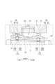
- FIG. 2 is a partially enlarged view of FIG.
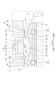
- FIG. 2 is a schematic diagram illustrating a rotating shaft rotating at a low rotation speed.
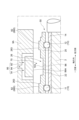
- FIG. 3 is a partially enlarged view of FIG. 2 .
- FIG. 11 is a schematic view showing an oil flow path protrusion according to another embodiment.
- expressions indicating that things are in an equal state such as “identical,””equal,” and “homogeneous,” not only indicate a state of strict equality, but also indicate a state in which there is a tolerance or a difference to the extent that the same function is obtained.
- expressions describing shapes such as a rectangular shape or a cylindrical shape do not only represent rectangular shapes or cylindrical shapes in the strict geometric sense, but also represent shapes that include uneven portions, chamfered portions, etc., to the extent that the same effect can be obtained.
- the expressions “comprise”, “include”, or “have” a certain element are not exclusive expressions excluding the presence of other elements.
- the same components are denoted by the same reference numerals and the description thereof may be omitted.
- FIG. 1 is a schematic diagram showing a turbocharger 1, which is a rotating machine according to one embodiment of the present disclosure.
- axial direction refers to the axial direction of the turbocharger 1.
- one side and the other side in the axial direction may be collectively referred to as "both sides in the axial direction.” Both sides in the axial direction refer to both the one side of the axial center of the rotating shaft 2 constituting the turbocharger 1 and the other side of the center.
- circumferential direction refers to the circumferential direction based on the axial direction.
- radial direction refers to the radial direction based on the axial direction
- radial inner side refers to the axial center side of the turbocharger 1
- radial outer side refers to the opposite side of the axial center of the turbocharger 1.
- the turbocharger 1 is configured to generate compressed air to be supplied to the engine using power obtained from the engine exhaust gas. More specifically, the turbocharger 1 has a rotating shaft 2, and a turbine impeller 6 and a compressor impeller 4 are connected to both ends of the rotating shaft 2, respectively. The turbine impeller 6 obtains rotational force from the engine exhaust gas as a working fluid to drive the turbocharger 1, and compressed air is generated by the rotation of the compressor impeller 4.
- the configuration of the turbocharger 1 according to one embodiment is shown, for example, in Publication No. 2020/170376. A detailed explanation of the configuration will be omitted in this article, and an overview will be provided below.
- turbocharger 1 includes a rotating shaft 2, a compressor impeller 4 provided on one end 2A of the rotating shaft 2, and a turbine impeller 6 provided on the other end 2B of the rotating shaft 2.
- the compressor impeller 4 is provided on a shaft 41 connected to one end 2A of the rotating shaft 2
- the turbine impeller 6 is provided on a shaft 61 connected to the other end 2B of the rotating shaft 2.
- the turbocharger 1 further includes a bearing 10 that rotatably supports the rotating shaft 2.
- the bearing 10 includes an inner ring 14 that extends in the axial direction on the outer periphery of the rotating shaft 2, and a plurality of rolling elements 13 that are arranged along the circumferential direction on the outer periphery of the inner ring 14.
- the inner ring 14 is fitted onto the outer periphery of the rotating shaft 2, and the inner ring 14 and the rotating shaft 2 can rotate together.
- An inner groove 15 that extends in the circumferential direction is formed on the outer periphery of the inner ring 14, and the plurality of rolling elements 13 can roll along the inner groove 15.
- the turbocharger 1 further includes an outer cylinder 20 that is provided outside each of the plurality of rolling elements 13.
- the outer cylinder 20 extends along the axial direction.
- the axial length of the outer cylinder 20 is approximately the same as the axial length of the inner ring 14.
- the outer cylinder 20 according to one embodiment of the present disclosure also functions as an outer ring of the bearing 10.
- the outer cylinder 20 includes a cylinder inner peripheral surface 22, and the cylinder inner peripheral surface 22 has an outer groove 25 extending in the circumferential direction.
- the above-mentioned plurality of rolling elements 13 can roll along the outer groove 25.
- each rolling element 13 is held by a retainer 29 between the inner groove 15 and the outer groove 25.
- the retainer 29 is in the shape of a ring extending in the circumferential direction.
- the retainer 29 is provided with a plurality of retaining holes into which the plurality of rolling elements 13 arranged at equal intervals in the circumferential direction are rotatably fitted.
- each rolling element 13 is held by a retaining hole and rolls along the inner groove 15 and the outer groove 25 (for the sake of simplicity, the retainer 29 is shown only in FIG. 1 and is omitted in FIGS. 2 to 5).
- the outer cylinder 20 is rotatable relative to the rolling elements 13.
- the outer cylinder 20 includes a cylinder outer peripheral surface 26 on the opposite side to the cylinder inner peripheral surface 22. The detailed shape of the cylinder outer peripheral surface 26 will be described later.
- the rotating shaft 2 the outer cylinder 20, the shaft 41, and the shaft 61 may be collectively referred to as the "rotating shaft unit 50."
- the axis (shaft center) of the rotating shaft unit 50 coincides with the axis (shaft center) of the rotating shaft 2.
- the rotating shaft unit 50 is configured to rotate integrally with the turbine impeller 6 and the compressor impeller 4.
- the turbocharger 1 further includes a housing 9 that accommodates at least the rotating shaft 2 of the rotating shaft unit 50.
- the housing 9 includes an opposing surface 99 that faces radially the outer circumferential surface 26 of the outer cylinder 20.
- the opposing surface 99 is disposed radially outward of the outer cylinder 20.
- the opposing surface 99 also extends circumferentially and faces the outer circumferential surface 26 over the entire circumferential length of the turbocharger 1.
- the housing 9 is formed with an oil supply passage 95 for allowing lubricating oil (not shown) to flow from the radial outside toward the outer cylinder 20.
- the oil supply passage 95 is disposed above the rotating shaft unit 50 (there is one oil supply passage 95).
- the lubricating oil supplied by the oil supply passage 95 flows into the oil axial flow passage 70 described below.
- the outer cylinder 20 and the housing 9 are configured to form an oil axis direction flow passage 70 between the cylinder outer peripheral surface 26 and the opposing surface 99.
- the oil axis direction flow passage 70 is a gap through which the lubricating oil (not shown) supplied by the oil supply passage 95 flows in the axial direction. Under a condition in which the lubricating oil is not supplied from the oil supply passage 95, the rotating shaft unit 50 is supported from below by the opposing surface 99 (not shown). At this time, the oil axis direction flow passage 70 is not formed at the place where the cylinder outer peripheral surface 26 and the opposing surface 99 contact each other.
- the rotating shaft unit 50 When the lubricating oil supplied from the oil supply passage 95 enters between the cylinder outer peripheral surface 26 and the opposing surface 99, the rotating shaft unit 50 is slightly separated from the opposing surface 99 by the oil film of the lubricating oil, and the oil axis direction flow passage 70 is formed in the circumferential direction (see FIG. 1).
- the lubricating oil flowing through the oil axis direction flow passage 70 flows radially outward through an oil discharge passage 96 (see FIG. 1) formed in the housing 9.
- the oil discharge passage 96 is located on the opposite side of the rotating shaft 2 to the oil supply passage 95 .
- the cylinder outer peripheral surface 26 is one of the elements that define the shape of the oil axial flow path 70.
- the cylinder outer peripheral surface 26 has a first outer peripheral surface 261, a pair of second outer peripheral surfaces 262, a pair of third outer peripheral surfaces 263, a pair of fourth outer peripheral surfaces 264, and a pair of fifth outer peripheral surfaces 265.
- Each of these outer peripheral surfaces extends circumferentially over the entire circumferential length of the turbocharger 1.
- each of these outer peripheral surfaces is parallel to the axis (shaft center) of the rotating shaft 2.
- the first outer peripheral surface 261 is formed in the axial center of the rotating shaft 2.
- An oil guide port 103 is formed in the first outer peripheral surface 261.
- the lubricating oil flowing into the oil guide port 103 is supplied to the rolling elements 13 via the lubricating oil inner supply passage 98.
- a plurality of lubricating oil inner supply passages 98 are arranged at intervals along the circumferential direction.
- the first outer peripheral surface 261 and the opposing surface 99 are configured to form a relatively wide space in the radial direction within the oil axial flow passage 70.
- the pair of second outer peripheral surfaces 262 are disposed on both sides of the first outer peripheral surface 261 in the axial direction and radially outward of the first outer peripheral surface 261.
- the pair of third outer peripheral surfaces 263 are disposed on both sides of the second outer peripheral surface 262 in the axial direction and radially outward of the second outer peripheral surface 262.
- the pair of fourth outer peripheral surfaces 264 are disposed on both sides of the third outer peripheral surface 263 in the axial direction and are disposed at the same radial position as the pair of second outer peripheral surfaces 262.
- the pair of fifth outer peripheral surfaces 265 are disposed on both sides of the fourth outer peripheral surface 264 in the axial direction and are disposed at the same radial position as the first outer peripheral surface 261.
- the tube outer peripheral surface 26 has a pair of first connection surfaces 51, a pair of second connection surfaces 52, a pair of third connection surfaces 53, and a pair of fourth connection surfaces 54.
- Each first connection surface 51 connects an end of the first outer peripheral surface 261 to one end of each second outer peripheral surface 262.
- Each second connection surface 52 connects the other end of each second outer peripheral surface 262 to one end of each third outer peripheral surface 263.
- Each third connection surface 53 connects the other end of each third outer peripheral surface 263 to one end of each fourth outer peripheral surface 264.
- Each fourth connection surface 54 connects the other end of each fourth outer peripheral surface 264 to one end of each fifth outer peripheral surface 265.
- first connection surface 51, the second outer peripheral surface 262, the fourth outer peripheral surface 264, and the fourth connection surface 54 form a tube side base end convex portion 83.
- a tube side base end convex portion 83 is formed on the other side in the axial direction.
- a pair of tube side convex portions 82 protrude from the first outer peripheral surface 261 and the fifth outer peripheral surface 265 toward the opposing surface 99.
- the second connection surface 52, the third outer peripheral surface 263, and the third connection surface 53 form a tube side convex portion 82, and on the other axial side, a tube side convex portion 82 is similarly formed.
- a pair of tube side convex portions 82 each protrude from a pair of tube side base end convex portions 83 toward the opposing surface 99.
- the tube side base end convex portion 83 and the tube side convex portion 82 illustrated in FIG. 2 are formed integrally with the first outer peripheral surface 261, but the present disclosure is not limited to this. In other examples, the tube side base end convex portion 83 and the tube side convex portion 82 may be configured separately from the first outer peripheral surface 261. In all examples, the tube side base end convex portion 83 and the tube side convex portion 82 are provided on the tube outer peripheral surface 26.
- the opposing surface 99 is one of the elements that define the shape of the oil axial flow passage 70.
- the opposing surface 99 has a central opposing surface 191 that faces the first outer peripheral surface 261 and the pair of second outer peripheral surfaces 262, a pair of prescribed opposing surfaces 193 that are respectively arranged on both axial sides of the central opposing surface 191, and a pair of outer opposing surfaces 192 that are respectively arranged on both axial sides of the pair of prescribed opposing surfaces 193.
- the central opposing surface 191 and the pair of outer opposing surfaces 192 are arranged at the same radial position, and the pair of prescribed opposing surfaces 193 are arranged radially inward of the central opposing surface 191.
- the central opposing surface 191, the prescribed opposing surfaces 193, and the outer opposing surfaces 192 are parallel to the axial direction.
- the facing surface 99 has a pair of inner connection surfaces 198 and a pair of outer connection surfaces 199.
- Each inner connection surface 198 is connected to an end of the central facing surface 191 and one end of each specified facing surface 193.
- Each outer connection surface 199 is connected to the other end of each specified facing surface 193 and one end of each outer facing surface 192.
- the inner connection surface 198, the specified opposing surface 193, and the outer connection surface 199 form a housing side protrusion 88.
- a housing side protrusion 88 is formed on the other side in the axial direction.
- the pair of housing side protrusions 88 protrude from the central opposing surface 191 and the outer opposing surface 192 toward the tube outer peripheral surface 26.
- the housing side protrusion 88 illustrated in FIG. 2 is configured integrally with the central opposing surface 191, but the present disclosure is not limited to this. In other examples, the housing side protrusion 88 may be configured separately from the central opposing surface 191. In all examples, the housing side protrusion 88 is provided on the opposing surface 99.
- the axial range in which the pair of housing side protrusions 88 are arranged is included in the axial range in which the pair of tube side protrusions 82 are arranged.
- the oil flow passage convex portion 80 narrows the oil axial direction flow passage 70 in the radial direction. More specifically, on one side in the axial direction, a first narrow passage 71 is formed between the specified opposing surface 193 constituting the housing side convex portion 88 and the third outer peripheral surface 263 constituting the cylinder side convex portion 82. Furthermore, on the other side in the axial direction, a second narrow passage 72 is formed between the specified opposing surface 193 and the third outer peripheral surface 263.
- the multiple rolling elements 13 constituting the bearing 10 include multiple first rolling elements 11 arranged in the circumferential direction and multiple second rolling elements 12 arranged in the circumferential direction at an axial position away from the multiple first rolling elements 11.
- the multiple first rolling elements 11 are arranged on one axial side of the axial center of the rotating shaft 2, and the multiple second rolling elements 12 are arranged on the other axial side of the axial center.
- the inner groove 15 includes a first inner groove 15A into which the multiple first rolling elements 11 are rollably fitted, and a second inner groove 15B into which the multiple second rolling elements 12 are rollably fitted.
- the outer groove 25 includes a first outer groove 25A into which the multiple first rolling elements 11 are rollably fitted, and a second outer groove 25B into which the multiple second rolling elements 12 are rollably fitted.
- At least a portion of the oil flow passage protrusion 80 overlaps with the multiple rolling bodies 13 in the axial direction.
- at least a portion of the axial range in which the oil flow passage protrusion 80 is arranged overlaps with the axial range in which the multiple rolling bodies 13 are arranged.
- a pair of cylinder side protrusions 82 overlap with the first rolling body 11 and the second rolling body 12, respectively, in the axial direction
- a pair of housing side protrusions 88 also overlap with the first rolling body 11 and the second rolling body 12, respectively, in the axial direction.
- a first narrow passage 71 is formed in the axial range that overlaps with the first rolling body 11
- a second narrow passage 72 is formed in the axial range that overlaps with the second rolling body 12.
- FIG. 3 is a schematic diagram illustrating a rotating shaft 2 rotating at a low rotation speed.
- the rotation speed of the rotating shaft 2 is lower than the rated rotation speed. While the rotation speed is low, the radial displacement (amplitude) of the rotating shaft unit 50 is small, and the squeeze film effect is difficult to achieve. Therefore, the force for stabilizing the radial position of the rotating shaft unit 50 is weak, and there is a concern that the rotating shaft unit 50 will tilt with respect to the axial direction.
- the rotating shaft 2 tilts so that the first narrow passage 71 is narrower than the second narrow passage 72.
- the squeeze film effect is obtained when the rotation speed is low, there is a concern that the axial center position of the rotating shaft 2 will not be determined in the radial direction because the supporting force of the rotating shaft unit 50 is small.
- the oil flow path protrusion 80 is provided to form a first narrow path 71 and a second narrow path 72, with the first narrow path 71 overlapping with the first rolling body 11 in the axial direction, and the second narrow path 72 overlapping with the second rolling body 12 in the axial direction.
- the force generated by the Lomakin effect as the lubricating oil flows to both sides in the axial direction through the first narrow path 71 or the second narrow path 72 is easily transmitted to the rotating shaft 2 via the multiple rolling bodies 13.
- the force generated by the Lomakin effect is a force that tends to widen the narrowed flow path when the lubricating oil passes through a partially narrowed flow path.
- the first narrow passage 71 is narrower than the second narrow passage 72, and a stronger Lomakin effect is obtained in the first narrow passage 71 than in the second narrow passage 72.
- the force generated by the Lomakin effect indicated by the arrow F1 is easily transmitted to the rotating shaft 2 via at least one of the first rolling bodies 11. Therefore, the tilted attitude of the rotating shaft unit 50 is easily corrected, and the rotating shaft unit 50 can return to an attitude parallel to the axial direction (see FIG. 2). Note that even if the rotating shaft unit 50 is tilted so that the second narrow passage 72 is narrower than the first narrow passage 71, the tilted attitude of the rotating shaft unit 50 is corrected by the same principle. Therefore, a turbocharger 1 is realized that can stabilize the position of the axis of the rotating shaft 2 even when the rotation speed of the rotating shaft 2 is low.
- a turbocharger 1 is realized that can stabilize the position of the axis of the rotating shaft 2 regardless of the rotation speed of the rotating shaft 2.
- At least a portion of the oil flow path convex portion 80 is formed to overlap with the multiple first rolling bodies 11 and the multiple second rolling bodies 12 in the axial direction. More specifically, on one axial side, the cylinder side convex portion 82 and the housing side convex portion 88 overlap with the first rolling bodies 11 in the axial direction, and on the other axial side, the cylinder side convex portion 82 and the housing side convex portion 88 overlap with the second rolling bodies 12 in the axial direction.
- the multiple rolling elements 13 directly contact the inner peripheral surface 22 of the outer cylinder 20. More specifically, the multiple first rolling elements 11 directly contact the first inner groove 15A, and the multiple second rolling elements 12 directly contact the second inner groove 15B. With the above configuration, the outer cylinder 20 and the multiple rolling elements 13 are in direct contact with each other, so that the force due to the Lomakin effect is easily transmitted to the rotating shaft 2 via the first rolling elements 11 or the second rolling elements 12. This makes it easier to correct the tilted posture of the rotating shaft unit 50.
- the oil flow path convex portion 80 is formed so as to overlap in the axial direction with the position where the cylinder inner peripheral surface 22 and the rolling body 13 contact. More specifically, on one side in the axial direction, there are contact points P1, P2, and P3 where the first rolling body 11 and the first inner groove 15A contact.
- the contact point P1 is the contact point between the bottom surface of the first inner groove 15A and the first rolling body 11, and the contact points P2 and P3 are the contact points between a pair of side surfaces of the first inner groove 15A and the first rolling body 11.
- the cylinder side convex portion 82 and the housing side convex portion 88 are formed so as to overlap in the axial direction with the contact points P1, P2, and P3.
- the cylinder side convex portion 82 and the housing side convex portion 88 are formed so as to overlap in the axial direction with the contact points P1, P2, and P3.
- FIG. 4 is a partially enlarged view of FIG. 2.
- a portion of the pair of third outer peripheral surfaces 263 and a portion of the pair of prescribed opposing surfaces 193 are on both sides of the first rolling body 11 and the second rolling body 12 in the axial direction. More specifically, on one side in the axial direction, a portion of the cylinder side convex portion 82 and a portion of the housing side convex portion 88 both form a first oil flow path convex portion 81 located on the opposite side of the second rolling body 12 across the first rolling body 11.
- a portion of the cylinder side convex portion 82 and a portion of the housing side convex portion 88 both form a second oil flow path convex portion 84 located on the opposite side of the second rolling body 12 across the second rolling body 12 from the first oil flow path convex portion 81.
- the first narrow passage 71 and the second narrow passage 72 are also formed on both sides in the axial direction with respect to the multiple first rolling bodies 11 and the multiple second rolling bodies 12.
- the rotating shaft unit 50 is tilted, either the first narrow passage 71 or the second narrow passage 72 located on both sides in the axial direction becomes narrower, so the force obtained by the Romakin effect is large. Therefore, it becomes easier to correct the tilted attitude of the rotating shaft unit 50, and the position of the axis of the rotating shaft 2 can be further stabilized.
- the first oil flow path convex portion 81 does not have to be configured integrally with the cylinder side convex portion 82 and the housing side convex portion 88, and may be disposed at a distance from the cylinder side convex portion 82 and the housing side convex portion 88. Even in this case, the above-mentioned advantages can be obtained.
- Oil supply path 95 As shown in FIG. 4 , the oil supply passage 95 according to the embodiment of the present disclosure supplies lubricating oil to an oil shaft through a first oil inlet 101 and a second oil inlet 102 formed in an opposing surface 99.
- the first oil inlet 101 and the second oil inlet 102 are open in the central opposing surface 191 and are arranged to supply oil to the first rolling elements 11 and the second rolling elements 12 in the axial direction.
- the second rolling element 12 is disposed between the first rolling element 12 and the second rolling element 12 .
- the oil supply passage 95 includes a main flow passage 94, a first branch passage 91, and a second branch passage 92.
- the main flow passage 94 is disposed radially outward from the opposing surface 99, and is disposed axially between the first oil inlet 101 and the second oil inlet 102.
- the first oil inlet 101 is located on one side of the main flow passage 94 in the axial direction
- the second oil inlet 102 is located on the other side of the main flow passage 94 in the axial direction.
- the first branch passage 91 is connected to the main flow passage 94 and the first oil inlet 101
- the second branch passage 92 is connected to the main flow passage 94 and the second oil inlet 102.
- the lubricating oil supplied by the main flow passage 94 flows through the first branch passage 91 or the second branch passage 92.
- a portion of the lubricating oil flowing into the oil axial flow passage 70 from the first oil inlet 101 and the second oil inlet 102 flows toward the oil discharge passage 96.
- the other lubricating oil passes through the first narrow passage 71 or the second narrow passage 72 and flows to both sides in the axial direction.
- the first oil inlet 101 and the second oil inlet 102 are provided so as to be spaced apart from each other in the axial direction, and therefore the length of the flow path through which the lubricating oil flowing from the first oil inlet 101 into the oil axial flow path 70 flows to one side in the axial direction via the first narrow passage 71 can be shortened. Similarly, the length of the flow path through which the lubricating oil flowing from the second oil inlet 102 into the oil axial flow path 70 flows to the other side in the axial direction via the second narrow passage 72 can be shortened.
- FIG. 5 is a schematic diagram showing an oil flow passage convex portion 880 according to another embodiment.
- the opposing surface 99A of the housing 9A shown in the figure is a curved plane extending in the circumferential direction, and does not have unevenness like the opposing surface 99 (see FIG. 5).
- the oil flow passage convex portion 880 in the figure is provided only on the cylinder outer peripheral surface 26 of the cylinder outer peripheral surface 26 or the opposing surface 99.
- the oil flow passage convex portion 880 includes the cylinder side convex portion 82 and does not include the housing side convex portion 88 (see FIG. 5). According to the above configuration, it is not necessary to provide unevenness on the opposing surface 99 of the housing 9, and it is possible to simplify the shape of the opposing surface 99, and the configuration of the housing 9A can be simplified.
- the axial deviation between the axial midpoint of the tube side protrusion 82 and the center of the rolling body 13 is one-third or less of the diameter of the rolling body 13. More specifically, on one axial side, the axial deviation between the axial midpoint of the tube side protrusion 82 and the center of the first rolling body 11 is one-third or less, more specifically one-quarter or less, of the diameter of the first rolling body 11. On the other axial side, the axial deviation between the axial midpoint of the tube side protrusion 82 and the center of the second rolling body 12 is one-third or less, more specifically one-quarter or less, of the diameter of the second rolling body 12.
- the axial midpoint of the tube side protrusion 82 coincides with the axial midpoint of the third outer circumferential surface 263.
- the turbocharger 1 may have an oil flow passage convex portion (not shown) provided only on the opposing surface 99 out of the cylinder outer circumferential surface 26 or the opposing surface 99.
- This oil flow passage convex portion includes the housing side convex portion 88 and does not include the cylinder side convex portion 82.
- the rolling elements 13 do not need to include a plurality of second rolling elements 12. In this case, it is preferable that the plurality of first rolling elements 11 are disposed in the center of the axial direction of the rotating shaft 2.
- a single cylinder side convex portion 82 may be provided instead of the pair of cylinder side convex portions 82, and a single housing side convex portion 88 may be provided instead of the pair of housing side convex portions 88.
- the bearing 10 may include an outer ring configured separately from the outer tube 20.
- the outer ring may be interposed between the outer tube 20 and the rolling elements 13, and the above-mentioned outer groove 25 may be formed on the inner peripheral surface of the outer ring.
- the inner peripheral surface 22 of the outer tube 20 supports the rolling elements 13 so that they can roll.
- the tilted attitude of the rotating shaft unit 50 is corrected by the force generated by the Lomakin effect. Therefore, even if the rotation speed of the rotating shaft 2 is low, the position of the axis of the rotating shaft 2 can be stabilized.
- the fourth outer peripheral surface 264 and the fifth outer peripheral surface 265 illustrated in FIG. 2 may both be disposed at the same radial position as the third outer peripheral surface 263.
- the axial end of the tube side convex portion 82 may be included in the axial end of the outer tube 20.
- the axial length of the tube side convex portion 82 increases, improving the Romakin effect.
- the shape of the outer tube 20 is simplified, making it easier to manufacture the outer tube 20.
- the rotating machine of the present disclosure may be an electric compressor instead of the turbocharger 1.
- the turbine impeller 6 is not provided on the rotating shaft 2.
- a rotary machine includes: A rotating shaft (2); A compressor impeller (4) provided on one end (2A) side of the rotating shaft; A bearing (10) including a plurality of rolling elements (13) arranged along a circumferential direction on an outer circumferential side of the rotating shaft; an outer cylinder (20) provided radially outward of each of the plurality of rolling elements, the outer cylinder including a cylinder inner peripheral surface (22) that supports the plurality of rolling elements in a rotatable manner; a housing including an opposing surface (99, 99A) opposing an outer circumferential surface (26) of the outer cylinder, the housing (9, 9A) having an oil supply passage (95) formed therein for allowing lubricating oil to flow from a radially outer side of the opposing surface toward the outer cylinder; Equipped with The outer cylinder and the housing are configured to form an oil axial flow passage (70) between the cylinder outer circumferential surface and the opposing surface, the oil axial
- narrow passages (first narrow passage 71, second narrow passage 72) in the oil axial flow passage are formed by providing an oil flow passage protrusion, and at least a portion of the narrow passage overlaps with the multiple rolling elements in the axial direction.
- the force generated by the Lomakin effect as the lubricating oil passes through the narrow passage is easily transmitted to the rotating shaft via at least one of the multiple rolling elements. Therefore, even if the rotating shaft unit (50) including the rotating shaft, bearings, and outer cylinder is tilted when the rotating shaft rotation speed is low, the tilted attitude of the rotating shaft unit is easily corrected.
- a rotating machine is realized that can stabilize the position of the axis of the rotating shaft even when the rotating shaft rotation speed is low.
- the plurality of rolling elements are A plurality of first rolling elements (11) arranged in the circumferential direction; A plurality of second rolling bodies (12) arranged in the circumferential direction at axial positions spaced apart from the plurality of first rolling bodies; Including, At least a portion of the oil flow passage protrusion is formed so as to overlap with the plurality of first rolling elements and the plurality of second rolling elements in the axial direction.
- the narrow passage of the oil axial flow path includes a first narrow passage (71) that overlaps with the multiple first rolling bodies in the axial direction, and a second narrow passage (72) that overlaps with the multiple second rolling bodies in the axial direction.
- first narrow passage or the second narrow passage narrows and the other widens.
- the tilted attitude of the rotating shaft unit is then corrected by the Lomakin effect in the narrowed narrow passage. Since it is possible to correct the attitude of the rotating shaft unit regardless of the tilt of the rotating shaft unit, the position of the axis of the rotating shaft can be further stabilized.
- the oil flow path protrusion is a first oil flow path protrusion (81) located on the opposite side of the plurality of second rolling bodies with the plurality of first rolling bodies interposed therebetween in the axial direction; a second oil flow path protrusion (84) located on the opposite side of the first rolling bodies with the second rolling bodies interposed therebetween in the axial direction; Includes.
- narrow passages in the oil axial flow passage are formed on both axial sides of the multiple first rolling bodies and the multiple second rolling bodies.
- the oil supply passage includes: A main flow path (94) extending along the radial direction on the radially outer side of the opposing surface; a first branch passage (91) connected to the main flow path and a first oil inlet (101) opening in the opposing surface on one side of the main flow path in the axial direction; A second branch passage (92) connected to the main flow path and a second oil inlet (101) opening in the opposing surface on the other side opposite to the one side of the main flow path; Including, The first oil inlet and the second oil inlet are disposed between the first plurality of rolling bodies and the second plurality of rolling bodies in the axial direction.
- the configuration of 4) above makes it possible to shorten the length of the flow path through which the lubricating oil that flows from the first oil inlet into the oil axial flow path flows to one side in the axial direction via the first narrow passage. Similarly, it is possible to shorten the length of the flow path through which the lubricating oil that flows from the second oil inlet into the oil axial flow path flows to the other side in the axial direction via the second narrow passage.
- By reducing the flow path length it is possible to reduce pressure loss in the flow of the lubricating oil toward the outside in the axial direction, and it is possible to suppress stagnation of the flow of the lubricating oil. Therefore, since a force due to the Lomakin effect is continuously generated in the narrow passage, it becomes even easier to correct the tilted attitude of the rotating shaft unit and to further stabilize the position of the axis of the rotating shaft.
- the rotary machine according to any one of 1) to 4) above, The plurality of rolling elements directly contact the inner peripheral surface of the outer cylinder.
- the outer cylinder and the multiple rolling elements are in direct contact with each other, so the force caused by the Lomakin effect is easily transmitted to the rotating shaft via the multiple rolling elements. This makes it easier to correct the tilted position of the rotating shaft unit.
- the oil flow passage protrusion is formed so as to overlap in the axial direction with a position where the cylinder inner circumferential surface and the rolling element contact each other.
- the rotary machine according to any one of 1) to 6) above,
- the oil flow path protrusion is provided only on the cylindrical outer circumferential surface out of the cylindrical outer circumferential surface or the opposing surface.
- the oil flow path protrusion does not include a housing side protrusion, so it is possible to simplify the opposing surface of the housing. This simplifies the housing configuration.
- turbocharger 2 rotating shaft 2A: one end 2B: other end 4: compressor impeller 6: turbine impeller 9, 9A: housing 10: bearing 11: first rolling element 12: second rolling element 13: rolling element 14: inner ring 15: inner groove 15A: first inner groove 15B: second inner groove 20: outer cylinder 22: cylinder inner peripheral surface 25: outer groove 25A: first outer groove 25B: second outer groove 26: cylinder outer peripheral surface 41, 61: shaft 50: rotating shaft unit 51: first connecting surface 52: second connecting surface 53: third connecting surface 54: fourth connecting surface 70: oil axial flow passage 71: first narrow passage 72: second narrow passage 80: oil flow passage convex portion 81: first oil flow passage convex portion 82 : Cylinder side convex part 83 : Cylinder side base end convex part 84 : Second oil flow path convex part 88 : Housing side convex part 91 : First branch path 92 : Second branch path 94 : Main flow path 95 : Oil supply path 96 :
Landscapes
- Engineering & Computer Science (AREA)
- Mechanical Engineering (AREA)
- General Engineering & Computer Science (AREA)
- Chemical & Material Sciences (AREA)
- Combustion & Propulsion (AREA)
- Supercharger (AREA)
Abstract
回転機械は、複数の転動体を含む軸受と、複数の転動体を転動可能に支持する筒内周面を含む外筒と、外筒の筒外周面と対向する対向面を含み、対向面よりも径方向の外側から外筒に向かって潤滑油が流れるための油供給路が形成されるハウジングとを備える。外筒とハウジングは、筒外周面と対向面との間において、油供給路によって供給される潤滑油が軸方向に流れるための隙間である油軸方向流路を形成するように構成される。回転機械は、筒外周面に設けられると共に対向面に向かって突出する筒側凸部、または、対向面に設けられると共に筒外周面に向かって突出するハウジング側凸部の少なくとも一方を含む油流路凸部をさらに備える。油流路凸部の少なくとも一部は、軸方向において複数の転動体と重複するように形成される。
Description
本開示は、コンプレッサインペラが設けられる回転軸を備えた回転機械に関する。
特許文献1は、回転機械の一例としてターボチャージャを開示する。ターボチャージャは、回転軸と、回転軸の中央部分を収容する軸受ハウジングと、回転軸の一端に設けられるコンプレッサインペラと、回転軸の他端に設けられるタービンインペラと、回転軸の中央部分を回転自在に支持する軸受装置とを備える。また、軸受装置は、回転軸を回転自在に支持する転がり軸受けと、転がり軸受けを保持する保持部材とを含む。保持部材と軸受ハウジングとの間には、軸方向に延在する微小な隙間が潤滑油流路として形成される。ターボチャージャが動作するとき、潤滑油流路に供給される潤滑油によって、回転軸の振動が潤滑油によって吸収される。
回転軸の振動により潤滑油流路の径方向長さが変化すると、スクイーズフィルム効果により生じる力が保持部材に作用する。より具体的には、保持部材が軸受ハウジングに近づいて潤滑油流路が径方向にて狭まると、潤滑油流路にある潤滑油は圧縮され、潤滑油の流体的な抵抗力が保持部材に作用する。これにより、保持部材と軸受ハウジングとの接触の回避が期待される。
しかしながら、回転軸の回転数が低いときには、回転軸の振動が弱く、スクイーズフィルム効果は期待できない傾向にある。例えば、ターボチャージャが起動運転される間においては、スクイーズフィルム効果が期待できず、保持部材が傾いてしまい、軸受ハウジングと接触する可能性がある。また別の例を挙げると、回転数が低いときにスクイーズフィルム効果が得られたとしても、回転軸の支持力が小さいため、回転軸の軸心位置が径方向において定まらず、保持部材が軸受ハウジングと接触する可能性がある。
本開示の目的は、回転軸の回転数が低い場合であっても、回転軸の軸心の位置を安定化させることができる回転機械を提供することである。
本開示の少なくとも一実施形態に係る回転機械は、
回転軸と、
前記回転軸の一端側に設けられるコンプレッサインペラと、
前記回転軸の外周側で周方向に沿って配列される複数の転動体を含む軸受と、
前記複数の転動体の各々よりも径方向の外側に設けられた外筒であって、前記複数の転動体を転動可能に支持する筒内周面を含む外筒と、
前記外筒の筒外周面と対向する対向面を含むハウジングであって、前記対向面よりも前記径方向の外側から前記外筒に向かって潤滑油が流れるための油供給路が形成されるハウジングと、
を備え、
前記外筒と前記ハウジングは、前記筒外周面と前記対向面との間において、前記油供給路によって供給される前記潤滑油が軸方向に流れるための隙間である油軸方向流路を形成するように構成され、
前記筒外周面に設けられると共に前記対向面に向かって突出する筒側凸部、または、前記対向面に設けられると共に前記筒外周面に向かって突出するハウジング側凸部の少なくとも一方を含む油流路凸部をさらに備え、
前記油流路凸部の少なくとも一部は、前記軸方向において前記複数の転動体と重複するように形成される。
回転軸と、
前記回転軸の一端側に設けられるコンプレッサインペラと、
前記回転軸の外周側で周方向に沿って配列される複数の転動体を含む軸受と、
前記複数の転動体の各々よりも径方向の外側に設けられた外筒であって、前記複数の転動体を転動可能に支持する筒内周面を含む外筒と、
前記外筒の筒外周面と対向する対向面を含むハウジングであって、前記対向面よりも前記径方向の外側から前記外筒に向かって潤滑油が流れるための油供給路が形成されるハウジングと、
を備え、
前記外筒と前記ハウジングは、前記筒外周面と前記対向面との間において、前記油供給路によって供給される前記潤滑油が軸方向に流れるための隙間である油軸方向流路を形成するように構成され、
前記筒外周面に設けられると共に前記対向面に向かって突出する筒側凸部、または、前記対向面に設けられると共に前記筒外周面に向かって突出するハウジング側凸部の少なくとも一方を含む油流路凸部をさらに備え、
前記油流路凸部の少なくとも一部は、前記軸方向において前記複数の転動体と重複するように形成される。
本開示によれば、回転軸の回転数が低い場合であっても、回転軸の軸心の位置を安定化させることができる回転機械を提供できる。
以下、添付図面を参照して本開示の幾つかの実施形態について説明する。ただし、実施形態として記載されている又は図面に示されている構成部品の寸法、材質、形状、その相対的配置等は、本開示の範囲をこれに限定する趣旨ではなく、単なる説明例にすぎない。
例えば、「ある方向に」、「ある方向に沿って」、「平行」、「直交」、「中心」、「同心」或いは「同軸」等の相対的或いは絶対的な配置を表す表現は、厳密にそのような配置を表すのみならず、公差、若しくは、同じ機能が得られる程度の角度や距離をもって相対的に変位している状態も表すものとする。
例えば、「同一」、「等しい」及び「均質」等の物事が等しい状態であることを表す表現は、厳密に等しい状態を表すのみならず、公差、若しくは、同じ機能が得られる程度の差が存在している状態も表すものとする。
例えば、四角形状や円筒形状等の形状を表す表現は、幾何学的に厳密な意味での四角形状や円筒形状等の形状を表すのみならず、同じ効果が得られる範囲で、凹凸部や面取り部等を含む形状も表すものとする。
一方、一の構成要素を「備える」、「含む」、又は、「有する」という表現は、他の構成要素の存在を除外する排他的な表現ではない。
なお、同様の構成については同じ符号を付し説明を省略することがある。
例えば、「ある方向に」、「ある方向に沿って」、「平行」、「直交」、「中心」、「同心」或いは「同軸」等の相対的或いは絶対的な配置を表す表現は、厳密にそのような配置を表すのみならず、公差、若しくは、同じ機能が得られる程度の角度や距離をもって相対的に変位している状態も表すものとする。
例えば、「同一」、「等しい」及び「均質」等の物事が等しい状態であることを表す表現は、厳密に等しい状態を表すのみならず、公差、若しくは、同じ機能が得られる程度の差が存在している状態も表すものとする。
例えば、四角形状や円筒形状等の形状を表す表現は、幾何学的に厳密な意味での四角形状や円筒形状等の形状を表すのみならず、同じ効果が得られる範囲で、凹凸部や面取り部等を含む形状も表すものとする。
一方、一の構成要素を「備える」、「含む」、又は、「有する」という表現は、他の構成要素の存在を除外する排他的な表現ではない。
なお、同様の構成については同じ符号を付し説明を省略することがある。
図1は、本開示の一実施形態に係る回転機械であるターボチャージャ1を示す概略図である。以下の説明において、「軸方向」はターボチャージャ1の軸方向である。また、軸方向の一方側と他方側を総称して「軸方向の両側」という場合がある。軸方向の両側は、ターボチャージャ1を構成する回転軸2の軸方向中央部よりも一方側、および、該中央部よりも他方側の双方を指す。さらに以下の説明において、「周方向」は軸方向を基準とした周方向である。また、「径方向」は軸方向を基準とした径方向であり、「径方向の内側」はターボチャージャ1の軸心側であり、「径方向の外側」は、ターボチャージャ1の軸心とは反対側である。
ターボチャージャ1は、エンジンの排ガスから得られる動力によって、エンジンに供給するための圧縮空気を生成するように構成される。より詳細には、ターボチャージャ1は、回転軸2を備え、回転軸2の両端にはそれぞれタービンインペラ6およびコンプレッサインペラ4が連結される。そして、タービンインペラ6が作動流体としてのエンジンの排ガスから回転力を得ることによりターボチャージャ1は駆動し、コンプレッサインペラ4の回転によって圧縮空気が生成される。一実施形態に係るターボチャージャ1の構成は、例えば再表2020/170376号公報などにおいて示されている。本稿では構成の詳説を割愛し、以下に概要を例示する。
<1.ターボチャージャ1の構成の概要>
図1に示すように、ターボチャージャ1は、回転軸2と、回転軸2の一端2A側に設けられるコンプレッサインペラ4と、回転軸2の他端2B側に設けられるタービンインペラ6とを備える。コンプレッサインペラ4は、回転軸2の一端2Aに連結されるシャフト41に設けられ、タービンインペラ6は、回転軸2の他端2Bに連結されるシャフト61に設けられる。
図1に示すように、ターボチャージャ1は、回転軸2と、回転軸2の一端2A側に設けられるコンプレッサインペラ4と、回転軸2の他端2B側に設けられるタービンインペラ6とを備える。コンプレッサインペラ4は、回転軸2の一端2Aに連結されるシャフト41に設けられ、タービンインペラ6は、回転軸2の他端2Bに連結されるシャフト61に設けられる。
ターボチャージャ1は、回転軸2を回転自在に支持する軸受10をさらに備える。本例の軸受10は、回転軸2の外周側で軸方向に延在する内輪14と、内輪14の外周面にて周方向に沿って配列される複数の転動体13とを含む。内輪14は回転軸2の外周部に嵌まっており、内輪14と回転軸2は一体的に回転可能である。内輪14の外周面には周方向に延在する内溝15が形成されており、複数の転動体13は内溝15に沿って転動可能である。
ターボチャージャ1は、複数の転動体13の各々よりも外側に設けられる外筒20をさらに備える。外筒20は軸方向に沿って延在する。外筒20の軸方向長さは内輪14の軸方向長さと略同じである。本開示の一実施形態に係る外筒20は、軸受10の外輪としての機能を兼ね備える。具体的には、外筒20は筒内周面22を含み、筒内周面22は周方向に延在する外溝25を有する。上述の複数の転動体13は、外溝25に沿って転動可能である。より具体的な構成を説明すると、各転動体13は、内溝15と外溝25との間において保持器29によって保持されている。保持器29は周方向に延在するリング状である。保持器29には、周方向において等間隔に配置される複数の転動体13がそれぞれ回転可能に嵌め込まれた複数の保持穴が設けられている。回転軸2が回転するとき、各転動体13は、保持穴によって保持された状態で内溝15と外溝25に沿って転動するようになっている(図面を簡略化する都合、保持器29は図1でのみ図示し、図2~図5では図示を省略する。)。なお、外筒20は複数の転動体13に対して相対的に回転可能である。さらに、外筒20は筒内周面22とは反対側の筒外周面26を含む。筒外周面26の詳細な形状は後述する。
以下の説明では、回転軸2、外筒20、シャフト41、および、シャフト61を総称して「回転軸ユニット50」という場合がある。回転軸ユニット50の軸線(軸心)は回転軸2の軸線(軸心)と一致する。回転軸ユニット50は、タービンインペラ6およびコンプレッサインペラ4と一体的に回転するように構成される。
ターボチャージャ1は、回転軸ユニット50の回転軸2を少なくとも収容するハウジング9をさらに備える。ハウジング9は、外筒20の筒外周面26と径方向に対向する対向面99を含む。対向面99は外筒20よりも径方向の外側に配置される。また、対向面99は周方向に延在しており、ターボチャージャ1の周方向全長に亘って、筒外周面26と対向する。ハウジング9には、径方向の外側から外筒20に向かって潤滑油(図示外)が流れるための油供給路95が形成される。図1の例では、油供給路95は、回転軸ユニット50の上側に配置される(油供給路95の個数は1個である)。油供給路95によって供給される潤滑油は、以下で説明する油軸方向流路70に流入する。
<2.油軸方向流路70の概要>
図2は、図1の部分拡大図である。外筒20とハウジング9は、筒外周面26と対向面99との間において油軸方向流路70を形成するように構成される。油軸方向流路70は、油供給路95によって供給される潤滑油(図示外)が軸方向に流れるための隙間である。油供給路95から潤滑油が供給されていない状況下では、回転軸ユニット50は対向面99によって下から支えられる(図示外)。このとき、筒外周面26と対向面99とが接触する場所においては、油軸方向流路70が形成されない。油供給路95から供給される潤滑油が筒外周面26と対向面99との間に入り込むと、潤滑油の油膜によって回転軸ユニット50は対向面99からわずかに離れ、油軸方向流路70が周方向に亘って形成される(図1参照)。なお、油軸方向流路70を流れる潤滑油は、ハウジング9に形成される油排出路96(図1参照)を径方向の外側へ向けて流れるようになっている。油排出路96は、回転軸2を挟んで油供給路95とは反対側に位置する。
図2は、図1の部分拡大図である。外筒20とハウジング9は、筒外周面26と対向面99との間において油軸方向流路70を形成するように構成される。油軸方向流路70は、油供給路95によって供給される潤滑油(図示外)が軸方向に流れるための隙間である。油供給路95から潤滑油が供給されていない状況下では、回転軸ユニット50は対向面99によって下から支えられる(図示外)。このとき、筒外周面26と対向面99とが接触する場所においては、油軸方向流路70が形成されない。油供給路95から供給される潤滑油が筒外周面26と対向面99との間に入り込むと、潤滑油の油膜によって回転軸ユニット50は対向面99からわずかに離れ、油軸方向流路70が周方向に亘って形成される(図1参照)。なお、油軸方向流路70を流れる潤滑油は、ハウジング9に形成される油排出路96(図1参照)を径方向の外側へ向けて流れるようになっている。油排出路96は、回転軸2を挟んで油供給路95とは反対側に位置する。
図2に示すように、筒外周面26は、油軸方向流路70の形を規定する要素の1つである。本例の筒外周面26は、第1外周面261、一対の第2外周面262、一対の第3外周面263、一対の第4外周面264、および、一対の第5外周面265を有する。これらの外周面の各々は、ターボチャージャ1の周方向全長に亘って、周方向に延在する。また、これらの外周面の各々は、回転軸2の軸線(軸心)と平行である。
第1外周面261は回転軸2の軸方向中央部に形成される。第1外周面261には、油案内口103が形成されている。油案内口103に流入する潤滑油は、潤滑油内側供給路98を経由して転動体13に供給されるようになっている。本例では、複数の潤滑油内側供給路98が、周方向に沿って間隔を空けて配置されている。第1外周面261と、対向面99(より詳細には後述の中央対向面191)は、油軸方向流路70のなかで径方向に比較的広い空間を形成するように構成される。
一対の第2外周面262は、第1外周面261よりも軸方向の両側にそれぞれ配置されると共に、第1外周面261よりも径方向の外側に配置される。一対の第3外周面263は、一対の第2外周面262よりも軸方向の両側にそれぞれ配置されると共に、第2外周面262よりも径方向の外側に配置される。一対の第4外周面264は、一対の第3外周面263よりも軸方向の両側にそれぞれ配置されると共に、一対の第2外周面262と同じ径方向位置に配置される。一対の第5外周面265は、一対の第4外周面264よりも軸方向の両側にそれぞれ配置されると共に、第1外周面261と同じ径方向位置に配置される。
さらに、筒外周面26は、一対の第1接続面51、一対の第2接続面52、一対の第3接続面53、および、一対の第4接続面54を有する。各第1接続面51は、第1外周面261の端と各第2外周面262の一端とを接続する。各第2接続面52は、各第2外周面262の他端と各第3外周面263の一端とを接続する。各第3接続面53は、各第3外周面263の他端と各第4外周面264の一端とを接続する。各第4接続面54は、各第4外周面264の他端と各第5外周面265の一端とを接続する。
軸方向の一方側において、第1接続面51、第2外周面262、第4外周面264、および、第4接続面54は、筒側基端凸部83を形成する。軸方向の他方側においても同様に、筒側基端凸部83が形成される。一対の筒側凸部82は、第1外周面261および第5外周面265から対向面99に向かって突出する。
軸方向一方側において、第2接続面52、第3外周面263、および、第3接続面53は、筒側凸部82を形成し、軸方向他方側においても同様に筒側凸部82が形成される。一対の筒側凸部82は、それぞれ、一対の筒側基端凸部83から対向面99に向かって突出する。
図2で例示される筒側基端凸部83と筒側凸部82は、第1外周面261と一体的に形成されるが、本開示はこれに限定されない。他の例では、筒側基端凸部83と筒側凸部82は第1外周面261とは別体に構成されてもよい。いずれの例においても、筒側基端凸部83と筒側凸部82は、筒外周面26に設けられる。
対向面99は、油軸方向流路70の形を規定する要素の1つである。本例の対向面99は、第1外周面261および一対の第2外周面262に対向する中央対向面191と、中央対向面191に対して軸方向の両側のそれぞれ配置される一対の規定対向面193と、一対の規定対向面193に対して軸方向の両側にそれぞれ配置される一対の外側対向面192と、を有する。中央対向面191および一対の外側対向面192は互いに同じ径方向位置に配置され、一対の規定対向面193は中央対向面191よりも径方向の内側に配置される。中央対向面191、規定対向面193、および、外側対向面192は、軸方向と平行である。
さらに、対向面99は、一対の内側接続面198、および、一対の外側接続面199を有する。各内側接続面198は、中央対向面191の端と各規定対向面193の一端とに接続される。各外側接続面199は、各規定対向面193の他端と各外側対向面192の一端とに接続される。
軸方向の一方側において、内側接続面198、規定対向面193、および、外側接続面199は、ハウジング側凸部88を形成する。軸方向の他方側においても同様に、ハウジング側凸部88が形成される。一対のハウジング側凸部88は、中央対向面191および外側対向面192から筒外周面26に向かって突出する。図2で例示されるハウジング側凸部88は、中央対向面191と一体的に構成されるが、本開示はこれに限定されない。他の例では、ハウジング側凸部88は中央対向面191とは別体に構成されてもよい。いずれの例においても、ハウジング側凸部88は対向面99に設けられる。図2の例では、一対のハウジング側凸部88が配置される軸方向範囲は、一対の筒側凸部82が配置される軸方向範囲に含まれる。
以下、筒側凸部82およびハウジング側凸部88を総称して、「油流路凸部80」という場合がある。油流路凸部80は、油軸方向流路70を径方向において狭めている。より詳細には、軸方向の一方側において、ハウジング側凸部88を構成する規定対向面193と、筒側凸部82を構成する第3外周面263との間には、第1狭路71が形成される。さらに、軸方向の他方側において、規定対向面193と第3外周面263との間には、第2狭路72が形成される。
<3.転動体13>
図2に示すように、本開示の一実施形態では、軸受10(図1参照)を構成する複数の転動体13は、周方向に配列される複数の第1転動体11と、複数の第1転動体11から離れた軸方向位置にて周方向に配列される複数の第2転動体12とを含む。複数の第1転動体11は回転軸2の軸方向中央部よりも軸方向一方側に配置され、複数の第2転動体12は、該軸方向中央部よりも軸方向他方側に配置される。内溝15は、複数の第1転動体11が転動可能に嵌る第1内溝15Aと、複数の第2転動体12が転動可能に嵌る第2内溝15Bとを含む。また、外溝25は、複数の第1転動体11が転動可能に嵌る第1外溝25Aと、複数の第2転動体12が転動可能に嵌る第2外溝25Bとを含む。
図2に示すように、本開示の一実施形態では、軸受10(図1参照)を構成する複数の転動体13は、周方向に配列される複数の第1転動体11と、複数の第1転動体11から離れた軸方向位置にて周方向に配列される複数の第2転動体12とを含む。複数の第1転動体11は回転軸2の軸方向中央部よりも軸方向一方側に配置され、複数の第2転動体12は、該軸方向中央部よりも軸方向他方側に配置される。内溝15は、複数の第1転動体11が転動可能に嵌る第1内溝15Aと、複数の第2転動体12が転動可能に嵌る第2内溝15Bとを含む。また、外溝25は、複数の第1転動体11が転動可能に嵌る第1外溝25Aと、複数の第2転動体12が転動可能に嵌る第2外溝25Bとを含む。
本開示の一実施形態では、油流路凸部80の少なくとも一部は、軸方向において複数の転動体13と重複する。換言すると、油流路凸部80が配置される軸方向範囲の少なくとも一部は、複数の転動体13が配置される軸方向範囲と重複する。図2の例では、一対の筒側凸部82は、それぞれ、第1転動体11および第2転動体12と軸方向において重複し、且つ、一対のハウジング側凸部88も、それぞれ、第1転動体11および第2転動体12と軸方向において重複する。つまり、第1転動体11と重なる軸方向範囲に第1狭路71が形成されており、第2転動体12と重なる軸方向範囲に第2狭路72が形成されている。
<4.回転軸ユニット50の傾き矯正>
図3は、低い回転数で回転する回転軸2を例示する概略図である。例えばターボチャージャ1の起動運転などにおいては、回転軸2の回転数は定格回転数よりも低い。回転数が低い間においては、回転軸ユニット50の径方向における変位量(振幅)が小さく、スクイーズフィルム効果が発揮されにくい。従って、回転軸ユニット50の径方向位置を安定化させるための力が弱く、回転軸ユニット50が軸方向に対して傾くことが懸念される。図3の例では、第1狭路71が第2狭路72よりも狭くなるように回転軸2は傾く。また別の例を挙げると、回転数が低いときにスクイーズフィルム効果が得られたとしても、回転軸ユニット50の支持力が小さいため、回転軸2の軸心位置が径方向において定まらないことが懸念される。
図3は、低い回転数で回転する回転軸2を例示する概略図である。例えばターボチャージャ1の起動運転などにおいては、回転軸2の回転数は定格回転数よりも低い。回転数が低い間においては、回転軸ユニット50の径方向における変位量(振幅)が小さく、スクイーズフィルム効果が発揮されにくい。従って、回転軸ユニット50の径方向位置を安定化させるための力が弱く、回転軸ユニット50が軸方向に対して傾くことが懸念される。図3の例では、第1狭路71が第2狭路72よりも狭くなるように回転軸2は傾く。また別の例を挙げると、回転数が低いときにスクイーズフィルム効果が得られたとしても、回転軸ユニット50の支持力が小さいため、回転軸2の軸心位置が径方向において定まらないことが懸念される。
本実施形態では、油流路凸部80が設けられることで第1狭路71と第2狭路72が形成されており、第1狭路71は第1転動体11と軸方向に重複し、且つ、第2狭路72は第2転動体12と軸方向に重複する。潤滑油が第1狭路71または第2狭路72を経由して軸方向の両側へ流れることに伴ってロマキン効果により生じる力は、複数の転動体13を経由して回転軸2に伝わり易い。なお、ロマキン効果により生じる力は、部分的に狭まった流路を潤滑油が通過する際に、狭まった流路を広げようとする力である。
図3の例では、第1狭路71が第2狭路72よりも狭く、第2狭路72よりも第1狭路71において強いロマキン効果が得られる。矢印F1で示されるロマキン効果によって生じる力が、複数の第1転動体11の少なくとも1つを経由して回転軸2に伝わり易い。従って、回転軸ユニット50の傾いた姿勢は容易に矯正されて、回転軸ユニット50は軸方向と平行となる姿勢に復帰できる(図2参照)。なお、第2狭路72が第1狭路71よりも狭くなるように回転軸ユニット50が傾いた場合も、回転軸ユニット50の傾いた姿勢は同様の原理により矯正される。よって、回転軸2の回転数が低い場合であっても、回転軸2の軸心の位置を安定化させることができるターボチャージャ1が実現される。
また、回転軸2の回転数がさらに増大すれば、回転軸ユニット50の径方向における振動の程度が増大し、スクイーズフィルム効果が得られる。これにより、回転軸ユニット50をハウジング9から離すための力が外筒20に追加的に作用する。つまり、回転軸2の回転数が高い場合においても、回転軸ユニット50とハウジング9との接触を抑制できる。これにより、回転軸ユニット50の振動がハウジング9に伝わることに起因する異音の発生を抑制できる。以上のように本開示では、回転軸2の回転数に関わらず、回転軸2の軸心の位置を安定化させることができるターボチャージャ1が実現される。
図2で例示される実施形態では、油流路凸部80の少なくとも一部は、複数の第1転動体11および複数の第2転動体12と、軸方向において重複するように形成される。より詳細には、軸方向一方側では筒側凸部82およびハウジング側凸部88は第1転動体11と軸方向において重なり、軸方向他方側では筒側凸部82およびハウジング側凸部88は第2転動体12と軸方向において重なる。
上記構成によれば、回転軸ユニット50が傾いた場合、第1狭路71または第2狭路72の一方が狭まり他方が広がる。そして、狭まった狭路におけるロマキン効果によって、回転軸ユニット50の傾いた姿勢は矯正される。回転軸ユニット50の傾き方に関わらず回転軸ユニット50の姿勢を矯正することが可能になるので、回転軸2の軸心の位置をより安定化させることができる。
また、図2で例示される一実施形態では、複数の転動体13は外筒20の筒内周面22に直接的に当接する。より詳細には、複数の第1転動体11は第1内溝15Aに直接的に当接し、複数の第2転動体12は第2内溝15Bに直接的に当接する。上記構成によれば、外筒20と複数の転動体13とが直接的に接触するため、ロマキン効果による力が第1転動体11または第2転動体12を介して回転軸2に伝わり易い。これにより、回転軸ユニット50の傾いた姿勢の矯正を容易化できる。
また、図2で例示される一実施形態では、油流路凸部80は、筒内周面22と転動体13とが接触する位置と軸方向において重複するように形成される。より詳細には、軸方向の一方側において、第1転動体11と第1内溝15Aとが接触する接触点として、接触点P1,P2,P3が存在する。接触点P1は、第1内溝15Aの底面と第1転動体11との接触点であり、接触点P2,P3は、第1内溝15Aの一対の側面と第1転動体11との接触点である。そして、軸方向の一方側において、筒側凸部82およびハウジング側凸部88は、接触点P1,P2,P3と軸方向において重複するように形成される。また、軸方向の他方側においても同様に、筒側凸部82およびハウジング側凸部88は接触点P1,P2,P3と軸方向において重複するように形成される。上記構成によれば、ロマキン効果による力が複数の転動体13にさらに伝わり易い。これにより、回転軸ユニット50の傾いた姿勢の矯正をさらに容易化できる。
図4は、図2の部分拡大図である。一対の第3外周面263の一部、および、一対の規定対向面193の一部は、第1転動体11および第2転動体12よりも軸方向の両側にある。より詳細には、軸方向の一方側において、筒側凸部82の一部およびハウジング側凸部88の一部はいずれも、第1転動体11を挟んで第2転動体12とは反対側に位置する第1油流路凸部81を構成する。そして、軸方向の他方側において、筒側凸部82の一部およびハウジング側凸部88の一部はいずれも、第2転動体12を挟んで第1油流路凸部81とは反対側に位置する第2油流路凸部84を構成する。
上記構成によれば、第1狭路71および第2狭路72は、複数の第1転動体11および複数の第2転動体12に対して軸方向の両側にも形成される。回転軸ユニット50が傾いた場合、軸方向の両側に位置する第1狭路71または第2狭路72のいずれか一方は、より狭まるので、ロマキン効果によって得られる力が大きい。よって、回転軸ユニット50の傾いた姿勢の矯正がさらに容易になり、回転軸2の軸心の位置をより安定化させることができる。なお、第1油流路凸部81は、筒側凸部82およびハウジング側凸部88と一体的に構成されていなくてもよく、筒側凸部82およびハウジング側凸部88に対して間隔を空けて配置されてもよい。この場合であっても、上記利点は得られる。
<5.油供給路95>
図4で示すように、本開示の一実施形態に係る油供給路95は、対向面99に形成される第1油流入口101および第2油流入口102を介して、潤滑油を油軸方向流路70に供給するように構成される。第1油流入口101と第2油流入口102は、中央対向面191において開口しており、軸方向において複数の第1転動体11と複数の第2転動体12との間に配置される。
図4で示すように、本開示の一実施形態に係る油供給路95は、対向面99に形成される第1油流入口101および第2油流入口102を介して、潤滑油を油軸方向流路70に供給するように構成される。第1油流入口101と第2油流入口102は、中央対向面191において開口しており、軸方向において複数の第1転動体11と複数の第2転動体12との間に配置される。
油軸方向流路70の具体的な構成を説明する。油供給路95は、主流路94、第1分岐路91、および、第2分岐路92を含む。主流路94は、対向面99よりも径方向の外側に配置されると共に、軸方向において第1油流入口101と第2油流入口102との間に配置される。第1油流入口101は主流路94よりも軸方向の一方側に位置し、第2油流入口102は主流路94よりも軸方向の他方側に位置する。
第1分岐路91は主流路94と第1油流入口101とに接続され、第2分岐路92は主流路94と第2油流入口102とに接続される。主流路94によって供給される潤滑油は、第1分岐路91または第2分岐路92を流れる。第1油流入口101と第2油流入口102から油軸方向流路70の流入する潤滑油の一部は、油排出路96に向かって流れる。他の潤滑油は、第1狭路71または第2狭路72を通過して軸方向の両側へ流れる。
上記構成によれば、軸方向に互いに離れた第1油流入口101と第2油流入口102とが設けられるので、第1油流入口101から油軸方向流路70に流入した潤滑油が第1狭路71を経由して軸方向の一方側へ流れる流路長を短くできる。同様に、第2油流入口102から油軸方向流路70に流入した潤滑油が第2狭路72を経由して軸方向の他方側へ流れる流路長を短くできる。流路長の低減により、軸方向の両側に向かう潤滑油の流れの圧損を低減でき、潤滑油の流れが滞るのを抑制できる。従って、第1狭路71または第2狭路72においてはロマキン効果による力が継続的に発生するので、回転軸ユニット50の傾いた姿勢の矯正がさらに容易になり、回転軸2の軸心の位置をより安定化させることができる。
<6.他の実施形態>
図5は他の実施形態に係る油流路凸部880を示す概略図である。同図で示されるハウジング9Aの対向面99Aは、周方向に延在する湾曲した平面であり、対向面99(図5参照)のような凹凸を有さない。同図における油流路凸部880は、筒外周面26または対向面99のうち筒外周面26のみに設けられる。つまり、油流路凸部880は、筒側凸部82を含みかつハウジング側凸部88(図5参照)を含まない。上記構成によれば、ハウジング9の対向面99に凹凸を設ける必要がなく、対向面99の形状を単純化することが可能になり、ハウジング9Aの構成を簡略化できる。
図5は他の実施形態に係る油流路凸部880を示す概略図である。同図で示されるハウジング9Aの対向面99Aは、周方向に延在する湾曲した平面であり、対向面99(図5参照)のような凹凸を有さない。同図における油流路凸部880は、筒外周面26または対向面99のうち筒外周面26のみに設けられる。つまり、油流路凸部880は、筒側凸部82を含みかつハウジング側凸部88(図5参照)を含まない。上記構成によれば、ハウジング9の対向面99に凹凸を設ける必要がなく、対向面99の形状を単純化することが可能になり、ハウジング9Aの構成を簡略化できる。
図5で示すように幾つかの実施形態では、筒側凸部82の軸方向中点と転動体13の中心との軸方向におけるずれ量は、転動体13の直径の3分の1以下である。より詳細には、軸方向の一方側では筒側凸部82の軸方向中点と第1転動体11の中心との軸方向におけるずれ量は、第1転動体11の直径の3分の1以下であり、より具体的には4分の1以下である。そして、軸方向の他方側では、筒側凸部82の軸方向中点と第2転動体12の中心との軸方向におけるずれ量は、第2転動体12の直径の3分の1以下であり、より具体的には4分の1以下である。なお、筒側凸部82の軸方向中点は、第3外周面263の軸方向中点と一致する。
上記構成によれば、回転軸ユニット50が傾いたとき、外筒20から転動体13に伝わるロマキン効果による力は、転動体13の中心に伝わり易い。ロマキン効果による力が転動体13の転動力に変換されることが抑制されるので、効率的に回転軸ユニット50の傾きを矯正することが可能になる。
なお、他の実施形態は、図5で示される実施形態に限定されない。筒外周面26または対向面99のうち対向面99のみに設けられる油流路凸部(図示外)をターボチャージャ1は備えてもよい。この油流路凸部は、ハウジング側凸部88を含みかつ筒側凸部82を含まない。また、転動体13は、複数の第2転動体12を含まなくてもよい。この場合、複数の第1転動体11は、回転軸2の軸方向の中央部に配置されることが好ましい。また、一対の筒側凸部82の代わりに単一の筒側凸部82が設けられてもよいし、一対のハウジング側凸部88の代わりに単一のハウジング側凸部88が設けられてもよい。
あるいは、軸受10は、外筒20とは別体に構成された外輪を含んでもよい。外輪は外筒20と転動体13との間に介在し、外輪の内周面に上述の外溝25が形成されてもよい。この場合であっても、外輪が外筒20に嵌め込まれる構成が採用されるので、外筒20の筒内周面22は転動体13を転動可能に支持していると了解される。
上記の他の実施形態のいずれにおいても、ロマキン効果によって生じる力により回転軸ユニット50の傾いた姿勢は矯正される。よって、回転軸2の回転数が低い場合であっても、回転軸2の軸心の位置を安定化させることができる。
さらに、図2で例示される第4外周面264と第5外周面265はいずれも、第3外周面263と同じ径方向位置に配置されてもよい。つまり、筒側凸部82の軸方向における端部が、外筒20の軸方向における端部に含まれてもよい。この場合、筒側凸部82の軸方向長さが増すので、ロマキン効果は向上する。また、筒外周面26に形成される段部の個数が図2で示される個数よりも減るので、外筒20の形状が簡易になり、外筒20の製造を易化できる。
さらに、本開示の回転機械は、ターボチャージャ1である代わりに電動コンプレッサであってもよい。この場合、回転軸2にはタービンインペラ6が設けられない。
<7.まとめ>
上述した幾つかの実施形態に記載の内容は、例えば以下のように把握される。
上述した幾つかの実施形態に記載の内容は、例えば以下のように把握される。
1)本開示の少なくとも一実施形態に係る回転機械(ターボチャージャ1)は、
回転軸(2)と、
前記回転軸の一端(2A)側に設けられるコンプレッサインペラ(4)と、
前記回転軸の外周側で周方向に沿って配列される複数の転動体(13)を含む軸受(10)と、
前記複数の転動体の各々よりも径方向の外側に設けられた外筒であって、前記複数の転動体を転動可能に支持する筒内周面(22)を含む外筒(20)と、
前記外筒の筒外周面(26)と対向する対向面(99,99A)を含むハウジングであって、前記対向面よりも前記径方向の外側から前記外筒に向かって潤滑油が流れるための油供給路(95)が形成されるハウジング(9,9A)と、
を備え、
前記外筒と前記ハウジングは、前記筒外周面と前記対向面との間において、前記油供給路によって供給される前記潤滑油が軸方向に流れるための隙間である油軸方向流路(70)を形成するように構成され、
前記筒外周面に設けられると共に前記対向面に向かって突出する筒側凸部(82)、または、前記対向面に設けられると共に前記筒外周面に向かって突出するハウジング側凸部(88)の少なくとも一方を含む油流路凸部(80,880)をさらに備え、
前記油流路凸部の少なくとも一部は、前記軸方向において前記複数の転動体と重複するように形成される。
回転軸(2)と、
前記回転軸の一端(2A)側に設けられるコンプレッサインペラ(4)と、
前記回転軸の外周側で周方向に沿って配列される複数の転動体(13)を含む軸受(10)と、
前記複数の転動体の各々よりも径方向の外側に設けられた外筒であって、前記複数の転動体を転動可能に支持する筒内周面(22)を含む外筒(20)と、
前記外筒の筒外周面(26)と対向する対向面(99,99A)を含むハウジングであって、前記対向面よりも前記径方向の外側から前記外筒に向かって潤滑油が流れるための油供給路(95)が形成されるハウジング(9,9A)と、
を備え、
前記外筒と前記ハウジングは、前記筒外周面と前記対向面との間において、前記油供給路によって供給される前記潤滑油が軸方向に流れるための隙間である油軸方向流路(70)を形成するように構成され、
前記筒外周面に設けられると共に前記対向面に向かって突出する筒側凸部(82)、または、前記対向面に設けられると共に前記筒外周面に向かって突出するハウジング側凸部(88)の少なくとも一方を含む油流路凸部(80,880)をさらに備え、
前記油流路凸部の少なくとも一部は、前記軸方向において前記複数の転動体と重複するように形成される。
上記1)の構成によれば、油流路凸部が設けられることで油軸方向流路の狭路(第1狭路71、第2狭路72)が形成され、狭路の少なくとも一部は軸方向において複数の転動体と重複する。これにより、潤滑油が狭路を通過することに伴いロマキン効果によって生じる力は、複数の転動体の少なくとも1つを経由して回転軸に伝わり易い。従って、回転軸の回転数が低いときに、回転軸、軸受、および、外筒を含む回転軸ユニット(50)が傾いても、回転軸ユニットの傾いた姿勢は容易に矯正される。よって、回転軸の回転数が低い場合であっても、回転軸の軸心の位置を安定化させることができる回転機械が実現される。
2)幾つかの実施形態では、上記1)に記載の回転機械であって、
前記複数の転動体は、
前記周方向に配列される複数の第1転動体(11)と、
前記複数の第1転動体から離れた軸方向位置にて前記周方向に配列される複数の第2転動体(12)と、
を含み、
前記油流路凸部の少なくとも一部は、前記複数の第1転動体および前記複数の第2転動体と、前記軸方向において重複するように形成される。
前記複数の転動体は、
前記周方向に配列される複数の第1転動体(11)と、
前記複数の第1転動体から離れた軸方向位置にて前記周方向に配列される複数の第2転動体(12)と、
を含み、
前記油流路凸部の少なくとも一部は、前記複数の第1転動体および前記複数の第2転動体と、前記軸方向において重複するように形成される。
上記2)の構成によれば、油軸方向流路の狭路は、複数の第1転動体と軸方向において重なる第1狭路(71)と、複数の第2転動体と軸方向において重なる第2狭路(72)とを含む。回転軸ユニットが傾いた場合、第1狭路または第2狭路の一方が狭まり他方が広がる。そして、狭まった狭路におけるロマキン効果によって、回転軸ユニットの傾いた姿勢は矯正される。回転軸ユニットの傾き方に関わらず回転軸ユニットの姿勢を矯正することが可能になるので、回転軸の軸心の位置をより安定化させることができる。
3)幾つかの実施形態では、上記2)に記載の回転機械であって、
前記油流路凸部は、
前記軸方向において、前記複数の第1転動体を挟んで前記複数の第2転動体とは反対側に位置する第1油流路凸部(81)と、
前記軸方向において、前記複数の第2転動体を挟んで前記複数の第1転動体とは反対側に位置する第2油流路凸部(84)と、
を含む。
前記油流路凸部は、
前記軸方向において、前記複数の第1転動体を挟んで前記複数の第2転動体とは反対側に位置する第1油流路凸部(81)と、
前記軸方向において、前記複数の第2転動体を挟んで前記複数の第1転動体とは反対側に位置する第2油流路凸部(84)と、
を含む。
上記3)の構成によれば、油軸方向流路の狭路は、複数の第1転動体および複数の第2転動体に対して軸方向の両側にも形成される。回転軸ユニットが傾いた場合に、これらの狭路はより狭まるため、ロマキン効果によって得られる力が大きい。よって、回転軸ユニットの傾いた姿勢の矯正がさらに容易になり、回転軸の軸心の位置をより安定化させることができる。
4)幾つかの実施形態では、上記2)または3)に記載の回転機械であって、
前記油供給路は、
前記対向面よりも前記径方向の外側で前記径方向に沿って延在する主流路(94)と、
前記主流路と、前記主流路よりも前記軸方向の一方側で前記対向面において開口する第1油流入口(101)とに接続される第1分岐路(91)と、
前記主流路と、前記主流路よりも前記一方側とは反対の他方側で前記対向面において開口する第2油流入口(101)とに接続される第2分岐路(92)と、
を含み、
前記第1油流入口と前記第2油流入口は、前記軸方向において、前記複数の第1転動体と前記複数の第2転動体との間に配置される。
前記油供給路は、
前記対向面よりも前記径方向の外側で前記径方向に沿って延在する主流路(94)と、
前記主流路と、前記主流路よりも前記軸方向の一方側で前記対向面において開口する第1油流入口(101)とに接続される第1分岐路(91)と、
前記主流路と、前記主流路よりも前記一方側とは反対の他方側で前記対向面において開口する第2油流入口(101)とに接続される第2分岐路(92)と、
を含み、
前記第1油流入口と前記第2油流入口は、前記軸方向において、前記複数の第1転動体と前記複数の第2転動体との間に配置される。
上記4)の構成によれば、第1油流入口から油軸方向流路に流入した潤滑油が第1狭路を経由して軸方向の一方側へ流れる流路長を短くできる。同様に、第2油流入口から油軸方向流路に流入した潤滑油が第2狭路を経由して軸方向の他方側へ流れる流路長を短くできる。流路長の低減により、軸方向の外側に向かう潤滑油の流れの圧損を低減でき、潤滑油の流れが滞るのを抑制できる。従って、狭路においてはロマキン効果による力が継続的に発生するので、回転軸ユニットの傾いた姿勢の矯正がさらに容易になり、回転軸の軸心の位置をより安定化させることができる。
5)幾つかの実施形態では、上記1)から4)のいずれかに記載の回転機械であって、
前記複数の転動体は、前記外筒の前記筒内周面に直接的に当接する。
前記複数の転動体は、前記外筒の前記筒内周面に直接的に当接する。
上記5)の構成によれば、外筒と複数の転動体とが直接的に接触するため、ロマキン効果による力が複数の転動体を介して回転軸に伝わり易い。これにより、回転軸ユニットの傾いた姿勢の矯正を容易化できる。
6)幾つかの実施形態では、上記5)に記載の回転機械であって、
前記油流路凸部は、前記筒内周面と前記転動体とが接触する位置と前記軸方向において重複するように形成される。
前記油流路凸部は、前記筒内周面と前記転動体とが接触する位置と前記軸方向において重複するように形成される。
上記6)の構成によれば、ロマキン効果による力が複数の転動体にさらに伝わり易い。これにより、回転軸ユニットの傾いた姿勢の矯正をさらに容易化できる。
7)幾つかの実施形態では、上記1)から6)のいずれかに記載の回転機械であって、
前記油流路凸部は、前記筒外周面または前記対向面のうち前記筒外周面のみに設けられる。
前記油流路凸部は、前記筒外周面または前記対向面のうち前記筒外周面のみに設けられる。
上記7)の構成によれば、油流路凸部がハウジング側凸部を含まないので、ハウジングの対向面を単純化することが可能になる。よってハウジングの構成を簡略化できる。
1 :ターボチャージャ
2 :回転軸
2A :一端
2B :他端
4 :コンプレッサインペラ
6 :タービンインペラ
9,9A :ハウジング
10 :軸受
11 :第1転動体
12 :第2転動体
13 :転動体
14 :内輪
15 :内溝
15A :第1内溝
15B :第2内溝
20 :外筒
22 :筒内周面
25 :外溝
25A :第1外溝
25B :第2外溝
26 :筒外周面
41,61 :シャフト
50 :回転軸ユニット
51 :第1接続面
52 :第2接続面
53 :第3接続面
54 :第4接続面
70 :油軸方向流路
71 :第1狭路
72 :第2狭路
80 :油流路凸部
81 :第1油流路凸部
82 :筒側凸部
83 :筒側基端凸部
84 :第2油流路凸部
88 :ハウジング側凸部
91 :第1分岐路
92 :第2分岐路
94 :主流路
95 :油供給路
96 :油排出路
98 :潤滑油内側供給路
99,99A :対向面
101 :第1油流入口
102 :第2油流入口
103 :油案内口
191 :中央対向面
192 :外側対向面
193 :規定対向面
198 :内側接続面
199 :外側接続面
261 :第1外周面
262 :第2外周面
263 :第3外周面
264 :第4外周面
265 :第5外周面
880 :油流路凸部
F1 :矢印
2 :回転軸
2A :一端
2B :他端
4 :コンプレッサインペラ
6 :タービンインペラ
9,9A :ハウジング
10 :軸受
11 :第1転動体
12 :第2転動体
13 :転動体
14 :内輪
15 :内溝
15A :第1内溝
15B :第2内溝
20 :外筒
22 :筒内周面
25 :外溝
25A :第1外溝
25B :第2外溝
26 :筒外周面
41,61 :シャフト
50 :回転軸ユニット
51 :第1接続面
52 :第2接続面
53 :第3接続面
54 :第4接続面
70 :油軸方向流路
71 :第1狭路
72 :第2狭路
80 :油流路凸部
81 :第1油流路凸部
82 :筒側凸部
83 :筒側基端凸部
84 :第2油流路凸部
88 :ハウジング側凸部
91 :第1分岐路
92 :第2分岐路
94 :主流路
95 :油供給路
96 :油排出路
98 :潤滑油内側供給路
99,99A :対向面
101 :第1油流入口
102 :第2油流入口
103 :油案内口
191 :中央対向面
192 :外側対向面
193 :規定対向面
198 :内側接続面
199 :外側接続面
261 :第1外周面
262 :第2外周面
263 :第3外周面
264 :第4外周面
265 :第5外周面
880 :油流路凸部
F1 :矢印
Claims (7)
- 回転軸と、
前記回転軸の一端側に設けられるコンプレッサインペラと、
前記回転軸の外周側で周方向に沿って配列される複数の転動体を含む軸受と、
前記複数の転動体の各々よりも径方向の外側に設けられた外筒であって、前記複数の転動体を転動可能に支持する筒内周面を含む外筒と、
前記外筒の筒外周面と対向する対向面を含むハウジングであって、前記対向面よりも前記径方向の外側から前記外筒に向かって潤滑油が流れるための油供給路が形成されるハウジングと、
を備え、
前記外筒と前記ハウジングは、前記筒外周面と前記対向面との間において、前記油供給路によって供給される前記潤滑油が軸方向に流れるための隙間である油軸方向流路を形成するように構成され、
前記筒外周面に設けられると共に前記対向面に向かって突出する筒側凸部、または、前記対向面に設けられると共に前記筒外周面に向かって突出するハウジング側凸部の少なくとも一方を含む油流路凸部をさらに備え、
前記油流路凸部の少なくとも一部は、前記軸方向において前記複数の転動体と重複するように形成される
回転機械。 - 前記複数の転動体は、
前記周方向に配列される複数の第1転動体と、
前記複数の第1転動体から離れた軸方向位置にて前記周方向に配列される複数の第2転動体と、
を含み、
前記油流路凸部の少なくとも一部は、前記複数の第1転動体および前記複数の第2転動体と、前記軸方向において重複するように形成される、
請求項1に記載の回転機械。 - 前記油流路凸部は、
前記軸方向において、前記複数の第1転動体を挟んで前記複数の第2転動体とは反対側に位置する第1油流路凸部と、
前記軸方向において、前記複数の第2転動体を挟んで前記複数の第1転動体とは反対側に位置する第2油流路凸部と、
を含む、
請求項2に記載の回転機械。 - 前記油供給路は、
前記対向面よりも前記径方向の外側で前記径方向に沿って延在する主流路と、
前記主流路と、前記主流路よりも前記軸方向の一方側で前記対向面において開口する第1油流入口とに接続される第1分岐路と、
前記主流路と、前記主流路よりも前記一方側とは反対の他方側で前記対向面において開口する第2油流入口とに接続される第2分岐路と、
を含み、
前記第1油流入口と前記第2油流入口は、前記軸方向において、前記複数の第1転動体と前記複数の第2転動体との間に配置される、
請求項2または3に記載の回転機械。 - 前記複数の転動体は、前記外筒の前記筒内周面に直接的に当接する、
請求項1または2に記載の回転機械。 - 前記油流路凸部は、前記筒内周面と前記転動体とが接触する位置と前記軸方向において重複するように形成される、
請求項5に記載の回転機械。 - 前記油流路凸部は、前記筒外周面または前記対向面のうち前記筒外周面のみに設けられる、
請求項1または2に記載の回転機械。
Priority Applications (2)
| Application Number | Priority Date | Filing Date | Title |
|---|---|---|---|
| JP2024576035A JPWO2024166345A1 (ja) | 2023-02-10 | 2023-02-10 | |
| PCT/JP2023/004514 WO2024166345A1 (ja) | 2023-02-10 | 2023-02-10 | 回転機械 |
Applications Claiming Priority (1)
| Application Number | Priority Date | Filing Date | Title |
|---|---|---|---|
| PCT/JP2023/004514 WO2024166345A1 (ja) | 2023-02-10 | 2023-02-10 | 回転機械 |
Publications (1)
| Publication Number | Publication Date |
|---|---|
| WO2024166345A1 true WO2024166345A1 (ja) | 2024-08-15 |
Family
ID=92262263
Family Applications (1)
| Application Number | Title | Priority Date | Filing Date |
|---|---|---|---|
| PCT/JP2023/004514 Ceased WO2024166345A1 (ja) | 2023-02-10 | 2023-02-10 | 回転機械 |
Country Status (2)
| Country | Link |
|---|---|
| JP (1) | JPWO2024166345A1 (ja) |
| WO (1) | WO2024166345A1 (ja) |
Citations (5)
| Publication number | Priority date | Publication date | Assignee | Title |
|---|---|---|---|---|
| JP2012036855A (ja) * | 2010-08-09 | 2012-02-23 | Ihi Corp | 転がり軸受を用いたターボチャージャ |
| JP2014020461A (ja) * | 2012-07-18 | 2014-02-03 | Jtekt Corp | ターボチャージャ用軸受装置 |
| JP2015081542A (ja) * | 2013-10-22 | 2015-04-27 | Ntn株式会社 | ターボチャージャ用軸受装置、およびターボチャージャ用軸受装置の製造方法 |
| WO2018070311A1 (ja) * | 2016-10-14 | 2018-04-19 | Ntn株式会社 | 過給機の軸受装置 |
| WO2019187023A1 (ja) * | 2018-03-30 | 2019-10-03 | 三菱重工エンジン&ターボチャージャ株式会社 | 回転機械、及びターボチャージャー |
-
2023
- 2023-02-10 WO PCT/JP2023/004514 patent/WO2024166345A1/ja not_active Ceased
- 2023-02-10 JP JP2024576035A patent/JPWO2024166345A1/ja active Pending
Patent Citations (5)
| Publication number | Priority date | Publication date | Assignee | Title |
|---|---|---|---|---|
| JP2012036855A (ja) * | 2010-08-09 | 2012-02-23 | Ihi Corp | 転がり軸受を用いたターボチャージャ |
| JP2014020461A (ja) * | 2012-07-18 | 2014-02-03 | Jtekt Corp | ターボチャージャ用軸受装置 |
| JP2015081542A (ja) * | 2013-10-22 | 2015-04-27 | Ntn株式会社 | ターボチャージャ用軸受装置、およびターボチャージャ用軸受装置の製造方法 |
| WO2018070311A1 (ja) * | 2016-10-14 | 2018-04-19 | Ntn株式会社 | 過給機の軸受装置 |
| WO2019187023A1 (ja) * | 2018-03-30 | 2019-10-03 | 三菱重工エンジン&ターボチャージャ株式会社 | 回転機械、及びターボチャージャー |
Also Published As
| Publication number | Publication date |
|---|---|
| JPWO2024166345A1 (ja) | 2024-08-15 |
Similar Documents
| Publication | Publication Date | Title |
|---|---|---|
| KR101970400B1 (ko) | 공기 베어링 및 회전체 시스템 | |
| US9599152B2 (en) | Compact squeeze film damper bearing | |
| US20170108035A1 (en) | Reversible spiral groove journal bearing for use on standard and reverse rotation turbochargers | |
| JP6168739B2 (ja) | ターボチャージャ用軸受装置 | |
| CN110382888B (zh) | 具有径向气体轴承的旋转系统 | |
| US20160208847A1 (en) | Quad foil journal air bearing | |
| US10077802B2 (en) | Tilting pad journal bearing assembly | |
| US10288112B2 (en) | Floating bush bearing device and supercharger provided with the same | |
| US10626795B2 (en) | Bearing assembly for a turbocharger, comprising an anti-rotation element | |
| US10753367B2 (en) | Mounting structure and turbocharger | |
| KR102240987B1 (ko) | 베어링 장치 및 회전기계 | |
| WO2018029836A1 (ja) | ジャーナル軸受及び回転機械 | |
| JP2010133530A (ja) | 軸受構造及び該軸受構造を備えた過給機 | |
| JP6559717B2 (ja) | メカニカルシール | |
| JP2010138753A (ja) | 過給機の軸受装置 | |
| JP2015172352A (ja) | ターボ圧縮機 | |
| US20210025403A1 (en) | Rotating machine and turbocharger | |
| WO2019087890A1 (ja) | ティルティングパッド軸受 | |
| KR102115855B1 (ko) | 저널 베어링 및 회전 기계 | |
| JP7243848B2 (ja) | 多円弧軸受、および、過給機 | |
| US11655851B2 (en) | Bearing device and rotating device | |
| US11460042B2 (en) | Floating bush bearing device and supercharger | |
| CN111316008B (zh) | 旋转机械、轴颈轴承 | |
| JP6403593B2 (ja) | ジャーナル軸受及び回転機械 | |
| WO2009144988A1 (ja) | フォイル軸受 |
Legal Events
| Date | Code | Title | Description |
|---|---|---|---|
| 121 | Ep: the epo has been informed by wipo that ep was designated in this application |
Ref document number: 23921174 Country of ref document: EP Kind code of ref document: A1 |
|
| WWE | Wipo information: entry into national phase |
Ref document number: 2024576035 Country of ref document: JP |
|
| NENP | Non-entry into the national phase |
Ref country code: DE |
|
| 122 | Ep: pct application non-entry in european phase |
Ref document number: 23921174 Country of ref document: EP Kind code of ref document: A1 |