WO2024166340A1 - ガス絶縁機器 - Google Patents
ガス絶縁機器 Download PDFInfo
- Publication number
- WO2024166340A1 WO2024166340A1 PCT/JP2023/004485 JP2023004485W WO2024166340A1 WO 2024166340 A1 WO2024166340 A1 WO 2024166340A1 JP 2023004485 W JP2023004485 W JP 2023004485W WO 2024166340 A1 WO2024166340 A1 WO 2024166340A1
- Authority
- WO
- WIPO (PCT)
- Prior art keywords
- conductor
- ring
- shaped
- rod
- gas
- Prior art date
- Legal status (The legal status is an assumption and is not a legal conclusion. Google has not performed a legal analysis and makes no representation as to the accuracy of the status listed.)
- Ceased
Links
Images

Classifications
-
- H—ELECTRICITY
- H01—ELECTRIC ELEMENTS
- H01H—ELECTRIC SWITCHES; RELAYS; SELECTORS; EMERGENCY PROTECTIVE DEVICES
- H01H1/00—Contacts
- H01H1/62—Heating or cooling of contacts
-
- H—ELECTRICITY
- H01—ELECTRIC ELEMENTS
- H01H—ELECTRIC SWITCHES; RELAYS; SELECTORS; EMERGENCY PROTECTIVE DEVICES
- H01H33/00—High-tension or heavy-current switches with arc-extinguishing or arc-preventing means
- H01H33/02—Details
- H01H33/025—Terminal arrangements
-
- H—ELECTRICITY
- H02—GENERATION; CONVERSION OR DISTRIBUTION OF ELECTRIC POWER
- H02B—BOARDS, SUBSTATIONS OR SWITCHING ARRANGEMENTS FOR THE SUPPLY OR DISTRIBUTION OF ELECTRIC POWER
- H02B13/00—Arrangement of switchgear in which switches are enclosed in, or structurally associated with, a casing, e.g. cubicle
- H02B13/02—Arrangement of switchgear in which switches are enclosed in, or structurally associated with, a casing, e.g. cubicle with metal casing
- H02B13/035—Gas-insulated switchgear
- H02B13/0358—Connections to in or out conductors
-
- H—ELECTRICITY
- H01—ELECTRIC ELEMENTS
- H01H—ELECTRIC SWITCHES; RELAYS; SELECTORS; EMERGENCY PROTECTIVE DEVICES
- H01H9/00—Details of switching devices, not covered by groups H01H1/00 - H01H7/00
- H01H9/52—Cooling of switch parts
- H01H2009/526—Cooling of switch parts of the high voltage switches
-
- H—ELECTRICITY
- H01—ELECTRIC ELEMENTS
- H01R—ELECTRICALLY-CONDUCTIVE CONNECTIONS; STRUCTURAL ASSOCIATIONS OF A PLURALITY OF MUTUALLY-INSULATED ELECTRICAL CONNECTING ELEMENTS; COUPLING DEVICES; CURRENT COLLECTORS
- H01R24/00—Two-part coupling devices, or either of their cooperating parts, characterised by their overall structure
- H01R24/58—Contacts spaced along longitudinal axis of engagement
Definitions
- This disclosure relates to gas-insulated equipment that houses multiple conductors that serve as paths for the main current inside a sealed container filled with insulating gas.
- gas-insulated equipment that houses multiple conductors that serve as the current path for the main current in a sealed container filled with insulating gas
- a method is used in which a ring-shaped conductor called a current-carrying contact is placed between the rod-shaped conductor and the tubular conductor at the electrical connection that electrically connects the rod-shaped conductor and the tubular conductor, and the rod-shaped conductor, tubular conductor, and ring-shaped conductor form part of the current path.
- gas-insulated equipment if the temperature of the part that serves as the current path for the main current rises, the current resistance increases, and the main current flowing through the current path may become smaller than the design current. For this reason, gas-insulated equipment requires a heat dissipation structure to suppress the temperature rise in parts that are expected to rise in temperature when current is applied, so as not to cause problems in the operation of the equipment.
- Patent Document 1 discloses a gas-insulated device in which the surface of the contact part, which is the heating element, and the surface of the metal shield, which is the heat receiving element, are blackened by anodizing to improve the heat transfer from the heating element to the heat receiving element.
- the ring-shaped conductor that forms part of the current path must be kept below a preset design upper limit temperature to prevent a decrease in the current flowing through the current path as described above.
- the gas-insulated equipment disclosed in Patent Document 1 can improve heat transfer by blackening it with anodizing, but since anodizing reduces electrical conductivity, when used with a ring-shaped conductor that connects conductors together, it is necessary to increase the area of the contact part between the ring-shaped conductor and the cylindrical conductor. This creates a problem in that, when the insulation distance between the electrical connection part and the sealed container is taken into account, the overall size of the equipment is inevitably increased.
- the present disclosure has been made in consideration of the above, and aims to obtain a gas-insulated device that achieves a smaller device size while suppressing the temperature rise of the ring-shaped conductor that electrically connects the rod-shaped conductor and the tubular conductor that form the current path for the main current.
- the gas-insulated device comprises a sealed container filled with insulating gas, a heat generating portion disposed inside the sealed container and generating heat when a main current is passed through it, a rod-shaped conductor forming a current path for the main current, and an electrical connection portion disposed inside the sealed container that is an electrical connection portion between the rod-shaped conductor and the tubular conductor into which the rod-shaped conductor is inserted and forming the current path for the main current.
- the electrical connection portion has a plurality of ring-shaped conductors disposed between the rod-shaped conductor and the tubular conductor.
- the plurality of ring-shaped conductors each comprise at least one first ring-shaped conductor and a second ring-shaped conductor disposed at a position farther from the heat generating portion than the first ring-shaped conductor.
- An insulating layer is provided between each of the first ring-shaped conductors and the tubular conductor, or between each of the first ring-shaped conductors and the rod-shaped conductor.
- the present disclosure has the effect of providing a gas-insulated device that achieves a reduced device size while suppressing the temperature rise of the ring-shaped conductor that electrically connects the rod-shaped conductor and the tubular conductor that form the current path for the main current.
- FIG. 1 is a cross-sectional view of a gas-insulated switchgear according to a first embodiment
- FIG. 1 is an enlarged view of an electrical connection portion of a gas-insulated switchgear according to a first embodiment
- FIG. 13 is an enlarged view of an electrical connection portion of a gas-insulated switchgear according to a second embodiment
- FIG. 13 is an enlarged view of an electrical connection portion of a gas-insulated switchgear according to a third embodiment
- FIG. 13 is an enlarged view of an electrical connection portion of a gas-insulated switchgear according to a fourth embodiment
- FIG. 13 is an enlarged view of an electrical connection portion of a gas-insulated switchgear according to a fifth embodiment.
- FIG. 1 is a cross-sectional view of a gas-insulated switchgear according to the first embodiment.
- the gas-insulated switchgear 50 according to the first embodiment which is a type of gas-insulated equipment, includes a cylindrical ground tank 1, a movable contact 5a, and a fixed contact 5b, and includes a switching section 4 insulated and supported in the ground tank 1, and a movable outer conductor 34 and a fixed outer conductor 36 arranged in a pair of bushings 22 extending above the ground tank 1.
- the ground tank 1 and the bushing 22 are integrally formed to form a sealed container in which insulating gas is sealed.
- the movable contact 5a is movable, and the open state and the closed state are switched by the movement of the movable contact 5a.
- An end plate 3a is installed at the end of the movable side of the ground tank 1, and an end plate 3b is installed at the end of the fixed side of the ground tank 1.
- the end plate 3a is disk-shaped with a hole formed in the center.
- the hole of the end plate 3a is closed by a cap 3c.
- the end plate 3b is disk-shaped with no holes.
- the direction from the fixed contactor 5b toward the movable contactor 5a is called the "moving side”
- the direction from the movable contactor 5a toward the fixed contactor 5b is called the "fixed side”.
- the state in which the movable contactor 5a and the fixed contactor 5b are in contact is called the “closed state”
- the state in which the movable contactor 5a is separated from the fixed contactor 5b is called the "open state”.
- the opening/closing unit 4 is a heat generating unit that generates heat when electricity is applied.
- the opening/closing unit 4 has a nozzle 11 arranged around the movable contact 5a, a conductor rod 14 connected to the movable contact 5a, a contact case 8 connected to the lower end of the movable outer conductor 34, a fixed support 16 connected to the lower end of the fixed outer conductor 36, and a fixed shield 15 supported by the fixed support 16.
- the conductor rod 14 is connected to an insulating rod 12 connected to a shaft 6 of an operating device (not shown) installed outside the ground tank 1 to operate the movable contact 5a.
- the opening/closing unit 4 is insulated and supported inside the ground tank 1 by the movable insulating support member 17 and the fixed insulating support member 10.
- the contact case 8 is cylindrical and made of a conductive material.
- the contact case 8 has a main body 81 that houses the contacts 33, and a cylindrical conductor 89 that protrudes from the main body 81 in the outer circumferential direction.
- the cylindrical conductor 89 is cylindrical and has a bottom surface 891.
- a step 341 is formed on the side of the movable outer conductor 34 that is connected to the cylindrical conductor 89, and the tip is a small-diameter rod-shaped conductor 88.
- the rod-shaped conductor 88 and the tubular conductor 89 form part of the current path of the main current. Therefore, the connection between the rod-shaped conductor 88 and the tubular conductor 89 forms an electrical connection part 40 that electrically connects the rod-shaped conductor 88 and the tubular conductor 89 that form the current path of the main current.
- the electrical connection part 40 includes four ring-shaped conductors 84a, 84b, 84c, and 84d.
- the contact 33 is installed inside the tube of the contact case 8.
- the contact 33 is a conductive cylinder with an intermediate plate 331 provided in the axial middle, and is in contact with the contact case 8.
- a hole is formed in the intermediate plate 331 of the contact 33, and the inner peripheral surface of the hole is in contact with the conductor rod 14.
- the conductor rod 14 passes through the hole formed in the intermediate plate 331 of the contact 33 and is connected to the insulating rod 12.
- the movable side outer conductor 34 is electrically connected to the conductor rod 14 via the contact case 8 and the contact 33.
- a movable shield 35 is attached to the conductor rod 14, surrounding the movable contact 5a from the outer periphery of the grounded tank 1.
- the movable shield 35 is disposed in the gap between the contact case 8 and the contact 33, and the end 351 facing the fixed shield 15 protrudes from the gap between the contact case 8 and the contact 33.
- the end 351 of the movable shield 35 comes into contact with the fixed shield 15.
- the space surrounded by the movable shield 35 and the contact 33 forms a puffer chamber 32 connected to the nozzle 11.
- a portion of the movable side of the movable shield 35 is stored in the gap between the contact case 8 and the contact 33, reducing the volume of the puffer chamber 32 and causing insulating gas to be sprayed from the nozzle 11.
- the arc formed between the movable contact 5a and the fixed contact 5b during the opening operation is cooled and extinguished by the insulating gas sprayed from the nozzle 11.
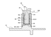
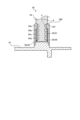
- FIG. 2 is an enlarged view of the electrical connection portion of the gas-insulated switchgear according to embodiment 1.
- the axial length of the rod-shaped conductor 88 is shorter than the axial length of the tubular conductor 89. Therefore, the step 341 of the movable-side outer conductor 34 abuts against the end 892 of the tubular conductor 89, and the tip 881 of the rod-shaped conductor 88 is not in contact with the bottom surface 891 of the tubular conductor 89.
- the tip 881 of the rod-shaped conductor 88 is also the tip 342 of the movable-side outer conductor 34.
- An insulating layer 85 is provided between a portion of the inner surface 893 of the tubular conductor 89 that is closer to the bottom surface 891 and the rod-shaped conductor 88.
- the insulating layer 85 is an insulating coating 91 formed on the inner surface 893 of the tubular conductor 89. As shown in FIG. 1, the bottom surface 891 is located closer to the opening/closing section 4 than the tubular conductor 89, so the insulating layer 85 can be considered to be provided on the portion of the inner surface 893 of the tubular conductor 89 that is closer to the opening/closing section 4.
- the ring-shaped conductors 84a, 84b, 84c, and 84d are fitted into each of the grooves of the rod-shaped conductor 88.
- the grooves in which the ring-shaped conductors 84a, 84b, 84c, and 84d are arranged are provided in the rod-shaped conductor 88 in the example described here, the grooves in which the ring-shaped conductors 84a, 84b, 84c, and 84d are arranged may be provided in the tubular conductor 89.
- the ring-shaped conductor 84a which is the furthest from the tip 881 of the rod-shaped conductor 88, is in contact with the tubular conductor 89, and the ring-shaped conductors 84b, 84c, and 84d, excluding the ring-shaped conductor 84a, are in contact with the insulating layer 85.
- the ring-shaped conductors 84b, 84c, and 84d that are in contact with the insulating layer 85 are the first ring-shaped conductors
- the ring-shaped conductor 84a is the second ring-shaped conductor that is positioned farther away from the opening/closing unit 4, which is the heat generating unit, than the first ring-shaped conductors 84b, 84c, and 84d.
- an insulating layer 85 is provided between a portion of the inner circumferential surface 893 of the tubular conductor 89 near the switching unit 4 and the rod-shaped conductor 88, and since no current flows through the first ring-shaped conductors 84b, 84c, and 84d, the current path of the main current between the movable contact 5a and the movable outer conductor 34 is the conductor rod 14, the contact 33, the main body 81, the tubular conductor 89, and the second ring-shaped conductor, ring-shaped conductor 84a. That is, as shown by the arrow A in FIG. 2, the main current passes only through the ring-shaped conductor 84a, and does not pass through the ring-shaped conductors 84b, 84c, and 84d.
- heat generated in the switching unit 4 is transferred to the rod-shaped conductor 88 via the conductor rod 14, the contact 33, the main body 81, the tubular conductor 89, and the ring-shaped conductors 84b, 84c, and 84d.
- the ring-shaped conductor 84a which is the current path, is located the furthest from the switching unit 4, which is the heat generating part, and is therefore least susceptible to the effects of heat from the switching unit 4.
- an insulating layer 85 is provided between a portion of the inner circumferential surface 893 of the cylindrical conductor 89 that is closer to the switchgear 4 and the rod-shaped conductor 88, and the ring-shaped conductors 84b, 84c, and 84d that are installed near the switchgear 4, which is a heat generating part, do not form a current path. Therefore, even if the temperature of the ring-shaped conductors 84b, 84c, and 84d that are installed near the switchgear 4, which is a heat generating part, rises, it does not affect the magnitude of the main current flowing in the current path.
- the ring-shaped conductor 84a which is installed farthest from the heat source, becomes the current path of the main current. Therefore, the temperature of the ring-shaped conductor 84a, which becomes the current path, is lower than that of the closer ring-shaped conductors 84b, 84c, and 84d, which are installed closer to the heat source.
- the heat dissipation area for dissipating heat from the ring-shaped conductor 84a, which is the current path of the main current, to below the design upper limit temperature is smaller than the heat dissipation area for dissipating heat from the ring-shaped conductors 84b, 84c, and 84d, which are not current paths of the main current, to below the design upper limit temperature. Therefore, in the gas-insulated switchgear 50 according to the first embodiment, the contact case 8 can be made smaller, so that the inner diameter of the ground tank 1, which is required for electrical insulation, is reduced, and the size of the equipment can be reduced.
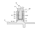
- Embodiment 2. 3 is an enlarged view of an electrical connection portion of a gas-insulated switchgear according to embodiment 2.
- the gas-insulated switchgear 50 according to embodiment 2 is similar to the gas-insulated switchgear 50 according to embodiment 1 except for the electrical connection portion 40.
- an insulating thin plate 92 is disposed between a part of an inner peripheral surface 893 of a cylindrical conductor 89 near a switching unit 4 (not shown in FIG. 3) and a rod-shaped conductor 88, and the insulating thin plate 92 forms an insulating layer 85.
- the configuration of the other portions is similar to that of the electrical connection portion 40 of the gas-insulated switchgear 50 according to embodiment 1.
- an insulating thin plate 92 arranged between a portion of the inner circumferential surface 893 of the tubular conductor 89 near the switching unit 4 (not shown in FIG. 3) and the rod-shaped conductor 88 forms an insulating layer 85, and since no current flows through the first ring-shaped conductors 84b, 84c, and 84d, the current path of the main current between the movable contact 5a and the movable outer conductor 34 is the conductor rod 14, the contact 33, the main body 81, the tubular conductor 89, and the second ring-shaped conductor, ring-shaped conductor 84a. That is, as shown by arrow A in FIG. 3, the main current passes only through the ring-shaped conductor 84a, and does not pass through the ring-shaped conductors 84b, 84c, and 84d.
- the heat generating part that generates heat when current is applied is the switchgear 4. Therefore, the heat generated in the switchgear 4 is transferred to the movable outer conductor 34 via the conductor rod 14, the contact 33, the main body 81, the tubular conductor 89, and the ring-shaped conductors 84b, 84c, and 84d.
- the ring-shaped conductor 84a which forms the current path, is located the farthest from the switchgear 4, which is the heat generating part, and is therefore least susceptible to the effects of heat from the switchgear 4.
- an insulating thin plate 92 arranged between a portion of the inner circumferential surface 893 of the cylindrical conductor 89 near the opening/closing unit 4 (not shown in FIG. 3) and the rod-shaped conductor 88 forms an insulating layer 85, and the ring-shaped conductors 84b, 84c, and 84d installed near the opening/closing unit 4, which is a heat generating part, do not form a current path.
- the ring-shaped conductor 84a installed farthest from the heat source becomes the current path of the main current, so the heat dissipation area for dissipating heat from the ring-shaped conductor 84a, which is the current path of the main current, to below the design upper limit temperature is smaller than the heat dissipation area for dissipating heat from the ring-shaped conductors 84b, 84c, and 84d, which are not current paths of the main current, to below the design upper limit temperature. Therefore, in the gas-insulated switchgear 50 according to the second embodiment, the contact case 8 can be made smaller, so the inner diameter of the ground tank 1 required for electrical insulation is smaller, making it possible to reduce the size of the equipment.
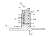
- Embodiment 3. 4 is an enlarged view of an electrical connection portion of a gas-insulated switchgear according to embodiment 3.
- the gas-insulated switchgear 50 according to embodiment 3 is similar to the gas-insulated switchgear 50 according to embodiment 1 except for the electrical connection portion 40.
- an insulating coating 94 provided on the portion of the ring-shaped conductors 84b, 84c, 84d that contacts the rod-shaped conductor 88 forms an insulating layer 85.
- the configuration of the other portions is similar to that of the electrical connection portion 40 of the gas-insulated switchgear 50 according to embodiment 1.
- the insulating coating 94 provided on the portions of the ring-shaped conductors 84b, 84c, and 84d that contact the rod-shaped conductor 88 forms the insulating layer 85, and since no current flows through the first ring-shaped conductors 84b, 84c, and 84d, the current path of the main current between the movable side contactor 5a and the movable side outer conductor 34 is the conductor rod 14, the contact 33, the main body 81, the tubular conductor 89, and the second ring-shaped conductor, ring-shaped conductor 84a. That is, as shown by the arrow A in FIG. 4, the main current passes only through the ring-shaped conductor 84a, and does not pass through the ring-shaped conductors 84b, 84c, and 84d.
- the heat generating part that generates heat when current is applied in the gas-insulated switchgear 50 according to the third embodiment is the switchgear 4. Therefore, the heat generated in the switchgear 4 is transferred to the movable outer conductor 34 via the conductor rod 14, the contact 33, the main body 81, the tubular conductor 89, and the ring-shaped conductors 84a, 84b, 84c, and 84d.
- the ring-shaped conductor 84a which forms the current path, is located the furthest from the switchgear 4, which is the heat generating part, and is therefore least susceptible to the effects of heat from the switchgear 4.
- the insulating coating 94 provided on the portions of the ring-shaped conductors 84b, 84c, and 84d that are in contact with the movable outer conductor 34 forms an insulating layer 85, and the ring-shaped conductors 84b, 84c, and 84d installed near the switchgear 4, which is a heat generating part, do not form a current path. Therefore, even if the temperature of the ring-shaped conductors 84b, 84c, and 84d installed near the switchgear 4, which is a heat generating part, rises, it does not affect the magnitude of the main current flowing in the current path.
- the ring-shaped conductor 84a installed farthest from the heat source becomes the current path of the main current, so the heat dissipation area for dissipating heat from the ring-shaped conductor 84a, which is the current path of the main current, to below the design upper limit temperature is smaller than the heat dissipation area for dissipating heat from the ring-shaped conductors 84b, 84c, and 84d, which are not current paths of the main current, to below the design upper limit temperature. Therefore, in the gas-insulated switchgear 50 according to the third embodiment, the contact case 8 can be made smaller, so the inner diameter of the ground tank 1 required for electrical insulation is smaller, making it possible to reduce the size of the equipment.
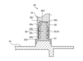
- Embodiment 4. 5 is an enlarged view of an electrical connection part of a gas-insulated switchgear according to embodiment 4.
- the gas-insulated switchgear 50 according to embodiment 4 is similar to the gas-insulated switchgear 50 according to embodiment 1 except for the electrical connection part 40.
- a hole extending in the axial direction is formed in the tip 342 of the movable-side outer conductor 34, and the tip part of the movable-side outer conductor 34 is a cylindrical conductor 89.
- the contact case 8 includes a rod-shaped conductor 88 extending in the outer circumferential direction of the main body 81 and a support part 87 that fixes the rod-shaped conductor 88 to the main body 81.
- the axial length of the rod-shaped conductor 88 is longer than the axial length of the cylindrical conductor 89. Therefore, the tip 881 of the rod-shaped conductor 88 abuts against the bottom surface 891 of the cylindrical conductor 89, and the tip 342 of the movable-side outer conductor 34 is not in contact with the support part 87.
- An insulating layer 85 is provided between the rod-shaped conductor 88 and a portion of the inner surface 893 of the cylindrical conductor 89 near the opening/closing unit 4 (not shown in FIG. 5) that generates heat when electricity is passed through it.
- the insulating layer 85 is an insulating coating 91 formed on the inner surface 893 of the cylindrical conductor 89.
- the ring-shaped conductors 84a, 84b, 84c, and 84d are fitted into each of the grooves of the rod-shaped conductor 88.
- the grooves in which the ring-shaped conductors 84a, 84b, 84c, and 84d are arranged are provided in the rod-shaped conductor 88 in the example described here, the grooves in which the ring-shaped conductors 84a, 84b, 84c, and 84d are arranged may be provided in the tubular conductor 89.
- the ring-shaped conductor 84a which is the furthest from the opening/closing portion 4, is in contact with the tubular conductor 89, and the ring-shaped conductors 84b, 84c, and 84d, excluding the ring-shaped conductor 84a, are in contact with the insulating layer 85.
- the ring-shaped conductors 84b, 84c, and 84d that are in contact with the insulating layer 85 are the first ring-shaped conductors
- the ring-shaped conductor 84a is the second ring-shaped conductor that is positioned farther away from the opening/closing unit 4, which is the heat generating unit, than the first ring-shaped conductors 84b, 84c, and 84d.
- an insulating layer 85 is provided between a portion of the inner circumferential surface 893 of the cylindrical conductor 89 near the switching unit 4 (not shown in FIG. 5) and the rod-shaped conductor 88, and the ring-shaped conductors 84b, 84c, and 84d installed near the switching unit 4 do not form a current path. Therefore, even if the temperature of the ring-shaped conductors 84b, 84c, and 84d installed near the switching unit 4, which is a heat generating part, rises, it does not affect the magnitude of the main current flowing in the current path.
- the ring-shaped conductor 84a which is installed farthest from the heat source, becomes the current path of the main current. Therefore, the temperature of the ring-shaped conductor 84a, which becomes the current path, is lower than that of the closer ring-shaped conductors 84b, 84c, and 84d, which are installed closer to the heat source.
- the heat dissipation area for dissipating heat from the ring-shaped conductor 84a, which is the current path of the main current, to below the design upper limit temperature is smaller than the heat dissipation area for dissipating heat from the ring-shaped conductors 84b, 84c, and 84d, which are not current paths of the main current, to below the design upper limit temperature. Therefore, in the gas-insulated switchgear 50 according to the fourth embodiment, the contact case 8 can be made smaller, so that the inner diameter of the ground tank 1, which is required for electrical insulation, is smaller, and the size of the equipment can be reduced.
- Embodiment 5. 6 is an enlarged view of an electrical connection part of a gas-insulated switchgear according to embodiment 5.
- the gas-insulated switchgear 50 according to embodiment 5 is similar to the gas-insulated switchgear 50 according to embodiment 1 except for the electrical connection part 40.
- the electrical connection part 40 of the gas-insulated switchgear 50 according to embodiment 5 includes a first cylindrical conductor 95 which is a part of the cylindrical conductor 89, and a second cylindrical conductor 96 which is a part of the cylindrical conductor 89.
- the second cylindrical conductor 96 is a cylindrical conductor that is thinner and shorter than the first cylindrical conductor 95, and is installed in the first cylindrical conductor 95, closer to the main body 81. Note that the opening/closing part 4, not shown in FIG.
- the first tubular conductor 95 is in contact with the main body portion 81 , but the second tubular conductor 96 is not in contact with the main body portion 81 .
- An insulating layer 85 is provided between the first tubular conductor 95 and the second tubular conductor 96.
- the insulating layer 85 is an insulating coating 91 formed on at least one of the portion of the first tubular conductor 95 that contacts the second tubular conductor 96 and the portion of the second tubular conductor 96 that contacts the first tubular conductor 95.
- the ring-shaped conductors 84a, 84b, 84c, and 84d are fitted into each of the grooves of the movable side outer conductor 34.
- the grooves in which the ring-shaped conductors 84a, 84b, 84c, and 84d are arranged are provided in the movable side outer conductor 34
- the grooves in which the ring-shaped conductors 84a, 84b, 84c, and 84d are arranged may also be provided in the first tubular conductor 95 and the second tubular conductor 96.
- the ring-shaped conductor 84a which is the furthest from the lower end of the movable-side outer conductor 34, is in contact with the first cylindrical conductor 95, and the ring-shaped conductors 84b, 84c, and 84d, excluding the ring-shaped conductor 84a, are in contact with the second cylindrical conductor 96.
- an insulating layer 85 is provided between the first tubular conductor 95 and the second tubular conductor 96, and since no current flows between the first tubular conductor 95 and the second tubular conductor 96, the main current path between the movable contact 5a and the movable outer conductor 34 is the conductor rod 14, the contact 33, the main body 81, the first tubular conductor 95, and the ring-shaped conductor 84a. As shown by the arrow A in FIG. 6, the main current passes only through the ring-shaped conductor 84a, and does not pass through the ring-shaped conductors 84b, 84c, and 84d.
- an insulating layer 85 is provided between the first cylindrical conductor 95 and the second cylindrical conductor 96, and similarly to the gas-insulated switchgear 50 according to the first embodiment, the ring-shaped conductors 84b, 84c, and 84d installed near the switchgear 4, which is a heat generating part, do not form a current path. Therefore, even if the temperature of the ring-shaped conductors 84b, 84c, and 84d installed near the switchgear 4, which is a heat generating part, rises, it does not affect the magnitude of the main current flowing in the current path.
- the ring-shaped conductor 84a which is installed farthest from the heat source, becomes the current path of the main current. Therefore, the temperature of the ring-shaped conductor 84a, which becomes the current path, is lower than that of the ring-shaped conductors 84b, 84c, and 84d, which are installed closer to the heat source.
- the heat dissipation area for dissipating heat from the ring-shaped conductor 84a, which is the current path of the main current, to below the design upper limit temperature is smaller than the heat dissipation area for dissipating heat from the ring-shaped conductors 84b, 84c, and 84d, which are not current paths of the main current, to below the design upper limit temperature. Therefore, in the gas-insulated switchgear 50 according to the fifth embodiment, the contact case 8 can be made smaller, so that the inner diameter of the ground tank 1, which is required for electrical insulation, is smaller, and the size of the equipment can be reduced.
Landscapes
- Engineering & Computer Science (AREA)
- Power Engineering (AREA)
- Gas-Insulated Switchgears (AREA)
- Installation Of Bus-Bars (AREA)
- Circuit Breakers (AREA)
Abstract
ガス絶縁開閉装置は、主電流の通電時に発熱する発熱部と、主電流の通電経路をなす棒状導体と筒状導体との電気的接続部分である電気的接続部(40)とを備え、電気的接続部(40)は、棒状導体(88)と筒状導体(89)との間に設置される複数のリング状導体(84a,84b,84c,84d)とを有し、複数のリング状導体(84a,84b,84c,84d)は、第1のリング状導体(84b,84c,84d)と、第1のリング状導体(84b,84c,84d)よりも発熱部から離れた位置に配置された第2のリング状導体(84a)とを備え、第1のリング状導体(84b,84c,84d)と筒状導体(89)との間、又は第1のリング状導体(84b,84c,84d)の各々と棒状導体(88)との間には、絶縁層(85)が設けられている。
Description
本開示は、絶縁ガスが封入された密閉容器内に主電流の通電経路となる複数の導体を収容したガス絶縁機器に関するものである。
絶縁ガスが封入された密閉容器内に主電流の通電経路となる複数の導体を収容したガス絶縁機器において、棒状導体と筒状導体とを電気的に接続する電気的接続部には、通電コンタクトと称されるリング状導体を棒状導体と筒状導体との間に配置する手法が用いられ、棒状導体、筒状導体及びリング状導体が通電経路の一部をなす。ガス絶縁機器において、主電流の通電経路となる部分の温度が上昇すると、通電抵抗が大きくなってしまい、通電経路に流れる主電流が設計上の電流よりも小さくなってしまうことがある。このため、ガス絶縁機器は、機器の運用上問題とならないように、通電時に温度上昇が見込まれる部分の温度上昇を抑えるための放熱構造が必要となる。
特許文献1には、発熱体である接点部の表面と、受熱体である金属シールドの表面とをアルマイト処理で黒色化することにより、発熱体から受熱体への伝熱性を高めたガス絶縁機器が開示されている。
密閉容器の内部において、通電経路の一部をなすリング状導体は、上記のように通電経路に流れる電流の減少を防ぐために、予め設定される設計上の上限温度以下に抑える必要がある。
特許文献1に開示されるガス絶縁機器は、アルマイト処理による黒色化により伝熱性を高めることができるものの、アルマイト処理により通電性が低下するため、導体同士を接続するリング状導体に適用する場合には、リング状導体の筒状導体との接触部の面積を大きくする必要がある。このため、電気的接続部と密閉容器との絶縁距離を考慮すると、機器全体の大型化が避けられないという問題がある。
本開示は、上記に鑑みてなされたものであって、主電流の通電経路をなす棒状導体と筒状導体とを電気的に接続するリング状導体の温度上昇を抑えつつ、機器サイズの小型化を実現したガス絶縁機器を得ることを目的とする。
上述した課題を解決し、目的を達成するために、本開示に係るガス絶縁機器は、絶縁ガスが封入された密閉容器と、密閉容器の内部に配置され、主電流の通電時に発熱する発熱部と、主電流の通電経路をなす棒状導体と、棒状導体が挿入されて主電流の通電経路をなす筒状導体との電気的接続部分であり、密閉容器の内部に配置された電気的接続部とを備える。電気的接続部は、棒状導体と筒状導体との間に設置される複数のリング状導体を有する。複数のリング状導体は、第1のリング状導体と、第1のリング状導体よりも発熱部から離れた位置に配置された第2のリング状導体とを少なくとも一つずつ備える。第1のリング状導体の各々と筒状導体との間、又は第1のリング状導体の各々と棒状導体との間には、絶縁層が設けられている。
本開示によれば、主電流の通電経路をなす棒状導体と筒状導体とを電気的に接続するリング状導体の温度上昇を抑えつつ、機器サイズの小型化を実現したガス絶縁機器を得られるという効果を奏する。
以下に、実施の形態に係るガス絶縁機器を図面に基づいて詳細に説明する。
実施の形態1.
図1は、実施の形態1に係るガス絶縁開閉装置の断面図である。ガス絶縁機器の一種である実施の形態1に係るガス絶縁開閉装置50は、筒状の接地タンク1と、可動側接触子5a及び固定側接触子5bを備えており、接地タンク1内に絶縁支持された開閉部4と、接地タンク1の上方に延びた1対のブッシング22内に配置された可動側外部導体34及び固定側外部導体36とを備える。なお、実施の形態1に係るガス絶縁開閉装置50において、接地タンク1とブッシング22とは一体に形成されて、絶縁ガスが封入される密閉容器を構成している。ガス絶縁開閉装置50は、可動側接触子5aが移動可能となっており、可動側接触子5aが移動することによって開極状態と閉極状態とが切り替わる。接地タンク1の可動側の端部には、端板3aが設置されており、接地タンク1の固定側の端部には、端板3bが設置されている。端板3aは、中央に穴が形成された円盤状である。端板3aの穴は、キャップ3cによって塞がれている。端板3bは、穴の無い円盤状である。なお、可動側接触子5aと固定側接触子5bとの配列方向において、固定側接触子5bから可動側接触子5aに向かう方向を「可動側」といい、可動側接触子5aから固定側接触子5bに向かう方向を「固定側」という。また、可動側接触子5aと固定側接触子5bとが接触した状態を「閉極状態」といい、可動側接触子5aが固定側接触子5bから離れた状態を「開極状態」という。
図1は、実施の形態1に係るガス絶縁開閉装置の断面図である。ガス絶縁機器の一種である実施の形態1に係るガス絶縁開閉装置50は、筒状の接地タンク1と、可動側接触子5a及び固定側接触子5bを備えており、接地タンク1内に絶縁支持された開閉部4と、接地タンク1の上方に延びた1対のブッシング22内に配置された可動側外部導体34及び固定側外部導体36とを備える。なお、実施の形態1に係るガス絶縁開閉装置50において、接地タンク1とブッシング22とは一体に形成されて、絶縁ガスが封入される密閉容器を構成している。ガス絶縁開閉装置50は、可動側接触子5aが移動可能となっており、可動側接触子5aが移動することによって開極状態と閉極状態とが切り替わる。接地タンク1の可動側の端部には、端板3aが設置されており、接地タンク1の固定側の端部には、端板3bが設置されている。端板3aは、中央に穴が形成された円盤状である。端板3aの穴は、キャップ3cによって塞がれている。端板3bは、穴の無い円盤状である。なお、可動側接触子5aと固定側接触子5bとの配列方向において、固定側接触子5bから可動側接触子5aに向かう方向を「可動側」といい、可動側接触子5aから固定側接触子5bに向かう方向を「固定側」という。また、可動側接触子5aと固定側接触子5bとが接触した状態を「閉極状態」といい、可動側接触子5aが固定側接触子5bから離れた状態を「開極状態」という。
開閉部4は、通電時に発熱する発熱部である。開閉部4は、可動側接触子5a及び固定側接触子5bに加え、可動側接触子5aの周囲に配置されたノズル11と、可動側接触子5aに連結された導体ロッド14と、可動側外部導体34の下端に接続されたコンタクトケース8と、固定側外部導体36の下端に接続された固定側サポート16と、固定側サポート16によって支持された固定側シールド15とを有する。導体ロッド14は、可動側接触子5aを操作するために接地タンク1外に設置された不図示の操作装置のシャフト6に連結された絶縁ロッド12に連結されている。開閉部4は、可動側絶縁支持部材17及び固定側絶縁支持部材10によって、接地タンク1の内部で絶縁支持されている。
コンタクトケース8は導電性材料で形成された筒状である。コンタクトケース8は、コンタクト33を収容する本体部81と、本体部81から外周方向に突出する筒状導体89を備えている。筒状導体89は、底面891を有する筒状である。
可動側外部導体34のうち筒状導体89に接続される側には、段差341が形成されており、先端部が小径の棒状導体88になっている。
実施の形態1において、棒状導体88及び筒状導体89は、主電流の通電経路の一部をなす。このため、棒状導体88と筒状導体89との接続部分は、主電流の通電経路をなす棒状導体88と筒状導体89とを電気的に接続する電気的接続部40となっている。電気的接続部40は、可動側外部導体34が有する棒状導体88及びコンタクトケース8が有する筒状導体89に加え、四つのリング状導体84a,84b,84c,84dを備える。
コンタクトケース8の筒内にはコンタクト33が設置されている。コンタクト33は、軸方向の中間部に中間板331が設けられた導電性の円筒であり、コンタクトケース8に接している。また、コンタクト33の中間板331には穴が形成されており、穴の内周面は、導体ロッド14に接している。導体ロッド14は、コンタクト33の中間板331に形成された穴を貫通して絶縁ロッド12に接続されている。可動側外部導体34は、コンタクトケース8及びコンタクト33を介して導体ロッド14と導通している。
導体ロッド14には、可動側接触子5aを接地タンク1の外周方向から囲む可動側シールド35が取り付けられている。可動側シールド35は、コンタクトケース8とコンタクト33との隙間に配置されており、固定側シールド15と対向する端部351は、コンタクトケース8とコンタクト33との隙間から突出している。可動側接触子5aと固定側接触子5bとが接触した閉極状態において、可動側シールド35の端部351は固定側シールド15に接触する。
可動側シールド35及びコンタクト33によって囲まれた空間は、ノズル11に繋がるパッファ室32になっている。閉極状態から開極状態に移行する開極動作の際には、可動側シールド35の可動側の一部分がコンタクトケース8とコンタクト33との隙間に収納されることにより、パッファ室32の容積が減少し、ノズル11から絶縁ガスが噴射される。開極動作時に可動側接触子5aと固定側接触子5bとの間に形成されるアークは、ノズル11から絶縁ガスが吹き付けられることによって、冷却されて消弧される。
図2は、実施の形態1に係るガス絶縁開閉装置の電気的接続部の拡大図である。棒状導体88の軸方向の長さは、筒状導体89の軸方向の長さよりも短い。このため、可動側外部導体34の段差341は、筒状導体89の端部892に突き当たっており、棒状導体88の先端881は、筒状導体89の底面891とは非接触になっている。棒状導体88の先端881は、可動側外部導体34の先端342でもある。
筒状導体89の内周面893のうち底面891寄りの一部分と棒状導体88との間には、絶縁層85が設けられている。絶縁層85は、筒状導体89の内周面893に形成された絶縁皮膜91である。図1に示したように、底面891は、筒状導体89よりも開閉部4の近くに位置しているため、絶縁層85は、筒状導体89の内周面893のうち、開閉部4寄りの一部分に設けられていると見なすことができる。
棒状導体88には、溝が四つ形成されている。リング状導体84a,84b,84c,84dは、棒状導体88の溝の各々に嵌め込まれている。なお、ここではリング状導体84a,84b,84c,84dが配置される溝が棒状導体88に設けられる構造を例としたが、リング状導体84a,84b,84c,84dが配置される溝は、筒状導体89に設けられていても良い。四つのリング状導体84a,84b,84c,84dのうち、棒状導体88の先端881から最も遠いリング状導体84aは、筒状導体89と接触しており、リング状導体84aを除いたリング状導体84b,84c,84dは、絶縁層85と接触している。リング状導体84a,84b,84c,84dのうち、絶縁層85と接触するリング状導体84b,84c,84dは、第1のリング状導体であり、リング状導体84aは、第1のリング状導体であるリング状導体84b,84c,84dよりも発熱部である開閉部4から離れた位置に配置された第2のリング状導体である。
実施の形態1に係るガス絶縁開閉装置50は、筒状導体89の内周面893のうち開閉部4寄りの一部分と棒状導体88との間に絶縁層85が設けられており、第1のリング状導体であるリング状導体84b,84c,84dには電流が流れないため、可動側接触子5aと可動側外部導体34との間の主電流の通電経路は、導体ロッド14、コンタクト33、本体部81、筒状導体89、第2のリング状導体であるリング状導体84aとなる。すなわち、図2に矢印Aで示すように、主電流は、リング状導体84aのみを通り、リング状導体84b,84c,84dを通らない。
実施の形態1に係るガス絶縁開閉装置50において、開閉部4において生じた熱は、導体ロッド14、コンタクト33、本体部81、筒状導体89及びリング状導体84b,84c,84dの経路を経て棒状導体88に伝わる。四つのリング状導体84a,84b,84c,84dのうち、通電経路となるリング状導体84aは、発熱部である開閉部4から最も遠くに配置されているため、開閉部4からの熱の影響を最も受けにくい。
実施の形態1に係るガス絶縁開閉装置50は、筒状導体89の内周面893のうち開閉部4寄りの一部分と棒状導体88との間に絶縁層85が設けられており、発熱部である開閉部4の近くに設置されたリング状導体84b,84c,84dは通電経路となっていない。したがって、発熱部である開閉部4の近くに設置されたリング状導体84b,84c,84dの温度が上昇しても、通電経路に流れる主電流の大きさには影響を及ぼさない。
実施の形態1に係るガス絶縁開閉装置50は、発熱源から最も遠くに設置されたリング状導体84aが主電流の通電経路となる。このため、通電経路となるリング状導体84aの温度は、より発熱源の近くに設置された近いリング状導体84b,84c,84dよりも低くなる。したがって、主電流の通電経路であるリング状導体84aを設計上の上限温度以下まで放熱するための放熱面積は、主電流の通電経路とはならないリング状導体84b,84c,84dを、設計上の上限温度以下まで放熱するための放熱面積よりも小さくなる。このため、実施の形態1に係るガス絶縁開閉装置50においては、コンタクトケース8を小型化できるため、電気的絶縁のために必要となる接地タンク1の内径が小さくなり、機器サイズを小さくすることが可能となる。
実施の形態2.
図3は、実施の形態2に係るガス絶縁開閉装置の電気的接続部の拡大図である。実施の形態2に係るガス絶縁開閉装置50は、電気的接続部40以外の部分は実施の形態1に係るガス絶縁開閉装置50と同様である。実施の形態2に係るガス絶縁開閉装置50の電気的接続部40においては、筒状導体89の内周面893のうち図3には不図示の開閉部4寄りの一部分と棒状導体88との間に、絶縁性薄板92が配置されており、絶縁性薄板92が絶縁層85を形成している。この他の部分の構成は、実施の形態1に係るガス絶縁開閉装置50の電気的接続部40と同様である。
図3は、実施の形態2に係るガス絶縁開閉装置の電気的接続部の拡大図である。実施の形態2に係るガス絶縁開閉装置50は、電気的接続部40以外の部分は実施の形態1に係るガス絶縁開閉装置50と同様である。実施の形態2に係るガス絶縁開閉装置50の電気的接続部40においては、筒状導体89の内周面893のうち図3には不図示の開閉部4寄りの一部分と棒状導体88との間に、絶縁性薄板92が配置されており、絶縁性薄板92が絶縁層85を形成している。この他の部分の構成は、実施の形態1に係るガス絶縁開閉装置50の電気的接続部40と同様である。
実施の形態2に係るガス絶縁開閉装置50は、筒状導体89の内周面893のうち図3には不図示の開閉部4寄りの一部分と棒状導体88との間に配置された絶縁性薄板92が絶縁層85を形成しており、第1のリング状導体であるリング状導体84b,84c,84dには電流が流れないため、可動側接触子5aと可動側外部導体34との間の主電流の通電経路は、導体ロッド14、コンタクト33、本体部81、筒状導体89、第2のリング状導体であるリング状導体84aとなる。すなわち、図3に矢印Aで示すように、主電流は、リング状導体84aのみを通り、リング状導体84b,84c,84dを通らない。
実施の形態1に係るガス絶縁開閉装置50と同様に、実施の形態2に係るガス絶縁開閉装置50において、通電時に発熱する発熱部は、開閉部4である。このため、開閉部4において生じた熱は、導体ロッド14、コンタクト33、本体部81、筒状導体89及びリング状導体84b,84c,84dの経路を経て可動側外部導体34に伝わる。四つのリング状導体84a,84b,84c,84dのうち、通電経路となるリング状導体84aは、発熱部である開閉部4から最も遠くに配置されているため、開閉部4からの熱の影響を最も受けにくい。
実施の形態2に係るガス絶縁開閉装置50は、筒状導体89の内周面893のうち図3には不図示の開閉部4寄りの一部分と棒状導体88との間に配置された絶縁性薄板92が絶縁層85を形成しており、発熱部である開閉部4の近くに設置されたリング状導体84b,84c,84dは通電経路となっていない。したがって、発熱部である開閉部4の近くに設置されたリング状導体84b,84c,84dの温度が上昇しても、通電経路に流れる主電流の大きさには影響を及ぼさない。
実施の形態2に係るガス絶縁開閉装置50は、実施の形態1に係るガス絶縁開閉装置50と同様に、発熱源から最も遠くに設置されたリング状導体84aが主電流の通電経路となるため、主電流の通電経路であるリング状導体84aを設計上の上限温度以下まで放熱するための放熱面積は、主電流の通電経路とはならないリング状導体84b,84c,84dを、設計上の上限温度以下まで放熱するための放熱面積よりも小さくなる。このため、実施の形態2に係るガス絶縁開閉装置50においては、コンタクトケース8を小型化できるため、電気的絶縁のために必要となる接地タンク1の内径が小さくなり、機器サイズを小さくすることが可能となる。
実施の形態3.
図4は、実施の形態3に係るガス絶縁開閉装置の電気的接続部の拡大図である。実施の形態3に係るガス絶縁開閉装置50は、電気的接続部40以外の部分は実施の形態1に係るガス絶縁開閉装置50と同様である。実施の形態3に係るガス絶縁開閉装置50の電気的接続部40においては、リング状導体84b,84c,84dのうち棒状導体88と接触する部分に設けられた絶縁皮膜94が絶縁層85を形成している。この他の部分の構成は、実施の形態1に係るガス絶縁開閉装置50の電気的接続部40と同様である。
図4は、実施の形態3に係るガス絶縁開閉装置の電気的接続部の拡大図である。実施の形態3に係るガス絶縁開閉装置50は、電気的接続部40以外の部分は実施の形態1に係るガス絶縁開閉装置50と同様である。実施の形態3に係るガス絶縁開閉装置50の電気的接続部40においては、リング状導体84b,84c,84dのうち棒状導体88と接触する部分に設けられた絶縁皮膜94が絶縁層85を形成している。この他の部分の構成は、実施の形態1に係るガス絶縁開閉装置50の電気的接続部40と同様である。
実施の形態3に係るガス絶縁開閉装置50は、リング状導体84b,84c,84dのうち棒状導体88と接触する部分に設けられた絶縁皮膜94が絶縁層85を形成しており、第1のリング状導体であるリング状導体84b,84c,84dには電流が流れないため、可動側接触子5aと可動側外部導体34との間の主電流の通電経路は、導体ロッド14、コンタクト33、本体部81、筒状導体89、第2のリング状導体であるリング状導体84aとなる。すなわち、図4に矢印Aで示すように、主電流は、リング状導体84aのみを通り、リング状導体84b,84c,84dを通らない。
実施の形態1に係るガス絶縁開閉装置50と同様に、実施の形態3に係るガス絶縁開閉装置50において通電時に発熱する発熱部は、開閉部4である。このため、開閉部4において生じた熱は、導体ロッド14、コンタクト33、本体部81、筒状導体89及びリング状導体84a,84b,84c,84dの経路を経て可動側外部導体34に伝わる。四つのリング状導体84a,84b,84c,84dのうち、通電経路となるリング状導体84aは、発熱部である開閉部4から最も遠くに配置されているため、開閉部4からの熱の影響を最も受けにくい。
実施の形態3に係るガス絶縁開閉装置50は、リング状導体84b,84c,84dのうち可動側外部導体34と接触する部分に設けられた絶縁皮膜94が絶縁層85を形成しており、発熱部である開閉部4の近くに設置されたリング状導体84b,84c,84dは通電経路となっていない。したがって、発熱部である開閉部4の近くに設置されたリング状導体84b,84c,84dの温度が上昇しても、通電経路に流れる主電流の大きさには影響を及ぼさない。
実施の形態3に係るガス絶縁開閉装置50は、実施の形態1に係るガス絶縁開閉装置50と同様に、発熱源から最も遠くに設置されたリング状導体84aが主電流の通電経路となるため、主電流の通電経路であるリング状導体84aを設計上の上限温度以下まで放熱するための放熱面積は、主電流の通電経路とはならないリング状導体84b,84c,84dを、設計上の上限温度以下まで放熱するための放熱面積よりも小さくなる。このため、実施の形態3に係るガス絶縁開閉装置50においては、コンタクトケース8を小型化できるため、電気的絶縁のために必要となる接地タンク1の内径が小さくなり、機器サイズを小さくすることが可能となる。
実施の形態4.
図5は、実施の形態4に係るガス絶縁開閉装置の電気的接続部の拡大図である。実施の形態4に係るガス絶縁開閉装置50は、電気的接続部40以外の部分は実施の形態1に係るガス絶縁開閉装置50と同様である。実施の形態4に係るガス絶縁開閉装置50の電気的接続部40においては、可動側外部導体34の先端342に軸方向に延びる穴が形成されており、可動側外部導体34の先端部が筒状導体89になっている。また、コンタクトケース8は、本体部81の外周方向に延びる棒状導体88と、棒状導体88を本体部81に固定する支持部87とを備えている。棒状導体88の軸方向の長さは、筒状導体89の軸方向の長さよりも長くなっている。このため、棒状導体88の先端881は、筒状導体89の底面891に突き当たっており、可動側外部導体34の先端342は、支持部87とは非接触になっている。
図5は、実施の形態4に係るガス絶縁開閉装置の電気的接続部の拡大図である。実施の形態4に係るガス絶縁開閉装置50は、電気的接続部40以外の部分は実施の形態1に係るガス絶縁開閉装置50と同様である。実施の形態4に係るガス絶縁開閉装置50の電気的接続部40においては、可動側外部導体34の先端342に軸方向に延びる穴が形成されており、可動側外部導体34の先端部が筒状導体89になっている。また、コンタクトケース8は、本体部81の外周方向に延びる棒状導体88と、棒状導体88を本体部81に固定する支持部87とを備えている。棒状導体88の軸方向の長さは、筒状導体89の軸方向の長さよりも長くなっている。このため、棒状導体88の先端881は、筒状導体89の底面891に突き当たっており、可動側外部導体34の先端342は、支持部87とは非接触になっている。
筒状導体89の内周面893のうち通電により発熱する図5には不図示の開閉部4寄りの一部分と棒状導体88との間には、絶縁層85が設けられている。絶縁層85は、筒状導体89の内周面893に形成された絶縁皮膜91である。
棒状導体88には、溝が四つ形成されている。リング状導体84a,84b,84c,84dは、棒状導体88の溝の各々に嵌め込まれている。なお、ここではリング状導体84a,84b,84c,84dが配置される溝が棒状導体88に設けられる構造を例としたが、リング状導体84a,84b,84c,84dが配置される溝は、筒状導体89に設けられていても良い。四つのリング状導体84a,84b,84c,84dのうち、開閉部4から最も遠いリング状導体84aは、筒状導体89と接触しており、リング状導体84aを除いたリング状導体84b,84c,84dは、絶縁層85と接触している。リング状導体84a,84b,84c,84dのうち、絶縁層85と接触するリング状導体84b,84c,84dは、第1のリング状導体であり、リング状導体84aは、第1のリング状導体であるリング状導体84b,84c,84dよりも発熱部である開閉部4から離れた位置に配置された第2のリング状導体である。
実施の形態4に係るガス絶縁開閉装置50は、筒状導体89の内周面893のうち図5には不図示の開閉部4寄りの一部分と棒状導体88との間に絶縁層85が設けられており、開閉部4の近くに設置されたリング状導体84b,84c,84dは通電経路となっていない。したがって、発熱部である開閉部4の近くに設置されたリング状導体84b,84c,84dの温度が上昇しても、通電経路に流れる主電流の大きさには影響を及ぼさない。
実施の形態4に係るガス絶縁開閉装置50は、発熱源から最も遠くに設置されたリング状導体84aが主電流の通電経路となる。このため、通電経路となるリング状導体84aの温度は、より発熱源の近くに設置された近いリング状導体84b,84c,84dよりも低くなる。したがって、主電流の通電経路であるリング状導体84aを設計上の上限温度以下まで放熱するための放熱面積は、主電流の通電経路とはならないリング状導体84b,84c,84dを、設計上の上限温度以下まで放熱するための放熱面積よりも小さくなる。このため、実施の形態4に係るガス絶縁開閉装置50においては、コンタクトケース8を小型化できるため、電気的絶縁のために必要となる接地タンク1の内径が小さくなり、機器サイズを小さくすることが可能となる。
実施の形態5.
図6は、実施の形態5に係るガス絶縁開閉装置の電気的接続部の拡大図である。実施の形態5に係るガス絶縁開閉装置50は、電気的接続部40以外の部分は実施の形態1に係るガス絶縁開閉装置50と同様である。実施の形態5に係るガス絶縁開閉装置50の電気的接続部40においては、筒状導体89の一部分である第1の筒状導体95と、筒状導体89の一部分である第2の筒状導体96とを備えている。第2の筒状導体96は、第1の筒状導体95よりも細くかつ短い筒状であり、第1の筒状導体95の筒内に、本体部81側に寄せて設置されている。なお、図6では不図示の開閉部4は、筒状導体89よりも本体部81側に設置されているため、第2の筒状導体96は、第1の筒状導体95の筒内において、開閉部4側に寄っている。第1の筒状導体95は、第2の筒状導体96が設置された部分よりも本体部81から離れた部分において内周面が露出している。第1の筒状導体95は本体部81に接触しているが、第2の筒状導体96は本体部81に接触していない。
図6は、実施の形態5に係るガス絶縁開閉装置の電気的接続部の拡大図である。実施の形態5に係るガス絶縁開閉装置50は、電気的接続部40以外の部分は実施の形態1に係るガス絶縁開閉装置50と同様である。実施の形態5に係るガス絶縁開閉装置50の電気的接続部40においては、筒状導体89の一部分である第1の筒状導体95と、筒状導体89の一部分である第2の筒状導体96とを備えている。第2の筒状導体96は、第1の筒状導体95よりも細くかつ短い筒状であり、第1の筒状導体95の筒内に、本体部81側に寄せて設置されている。なお、図6では不図示の開閉部4は、筒状導体89よりも本体部81側に設置されているため、第2の筒状導体96は、第1の筒状導体95の筒内において、開閉部4側に寄っている。第1の筒状導体95は、第2の筒状導体96が設置された部分よりも本体部81から離れた部分において内周面が露出している。第1の筒状導体95は本体部81に接触しているが、第2の筒状導体96は本体部81に接触していない。
第1の筒状導体95と第2の筒状導体96との間には、絶縁層85が設けられている。絶縁層85は、第1の筒状導体95のうち第2の筒状導体96に接する部分と、第2の筒状導体96のうち第1の筒状導体95に接する部分との少なくとも一方に形成された絶縁皮膜91である。
棒状導体である可動側外部導体34のうち筒状導体である第1の筒状導体95及び第2の筒状導体96に挿入される部分には、溝が四つ形成されている。リング状導体84a,84b,84c,84dは、可動側外部導体34の溝の各々に嵌め込まれている。なお、ここではリング状導体84a,84b,84c,84dが配置される溝が可動側外部導体34に設けられる構造を例としたが、リング状導体84a,84b,84c,84dが配置される溝は、第1の筒状導体95及び第2の筒状導体96に設けられていても良い。四つのリング状導体84a,84b,84c,84dのうち、可動側外部導体34の下端から最も遠いリング状導体84aは、第1の筒状導体95と接触しており、リング状導体84aを除いたリング状導体84b,84c,84dは、第2の筒状導体96と接触している。
実施の形態5に係るガス絶縁開閉装置50は、第1の筒状導体95と第2の筒状導体96との間に絶縁層85が設けられており、第1の筒状導体95と第2の筒状導体96との間には電流が流れないため、可動側接触子5aと可動側外部導体34との間の主電流の通電経路は、導体ロッド14、コンタクト33、本体部81、第1の筒状導体95、リング状導体84aとなる。図6に矢印Aで示すように、主電流は、リング状導体84aのみを通り、リング状導体84b,84c,84dを通らない。
実施の形態5に係るガス絶縁開閉装置50は、第1の筒状導体95と第2の筒状導体96との間に絶縁層85が設けられており、実施の形態1に係るガス絶縁開閉装置50と同様に、発熱部である開閉部4の近くに設置されたリング状導体84b,84c,84dは通電経路となっていない。したがって、発熱部である開閉部4の近くに設置されたリング状導体84b,84c,84dの温度が上昇しても、通電経路に流れる主電流の大きさには影響を及ぼさない。
実施の形態5に係るガス絶縁開閉装置50は、発熱源から最も遠くに設置されたリング状導体84aが主電流の通電経路となる。このため、通電経路となるリング状導体84aの温度は、より発熱源の近くに設置されたリング状導体84b,84c,84dよりも低くなる。したがって、主電流の通電経路であるリング状導体84aを設計上の上限温度以下まで放熱するための放熱面積は、主電流の通電経路とはならないリング状導体84b,84c,84dを、設計上の上限温度以下まで放熱するための放熱面積よりも小さくなる。このため、実施の形態5に係るガス絶縁開閉装置50においては、コンタクトケース8を小型化できるため、電気的絶縁のために必要となる接地タンク1の内径が小さくなり、機器サイズを小さくすることが可能となる。
以上の実施の形態に示した構成は、内容の一例を示すものであり、別の公知の技術と組み合わせることも可能であるし、要旨を逸脱しない範囲で、構成の一部を省略、変更することも可能である。
1 接地タンク、3a,3b 端板、3c キャップ、4 開閉部、5a 可動側接触子、5b 固定側接触子、6 シャフト、8 コンタクトケース、10 固定側絶縁支持部材、11 ノズル、12 絶縁ロッド、14 導体ロッド、15 固定側シールド、16 固定側サポート、17 可動側絶縁支持部材、22 ブッシング、32 パッファ室、33 コンタクト、34 可動側外部導体、35 可動側シールド、36 固定側外部導体、40 電気的接続部、50 ガス絶縁開閉装置、81 本体部、84a,84b,84c,84d リング状導体、85 絶縁層、87 支持部、88 棒状導体、89 筒状導体、91,94 絶縁皮膜、92 絶縁性薄板、95 第1の筒状導体、96 第2の筒状導体、331 中間板、341 段差、342,881 先端、351,892 端部、891 底面、893 内周面。
Claims (7)
- 絶縁ガスが封入された密閉容器と、
前記密閉容器の内部に配置され、主電流の通電時に発熱する発熱部と、
前記主電流の通電経路をなす棒状導体と、前記棒状導体が挿入されて前記主電流の通電経路をなす筒状導体との電気的接続部分であり、前記密閉容器の内部に配置された電気的接続部とを備え、
前記電気的接続部は、
前記棒状導体と前記筒状導体との間に設置される複数のリング状導体とを有し、
前記複数のリング状導体は、第1のリング状導体と、前記第1のリング状導体よりも前記発熱部から離れた位置に配置された第2のリング状導体とを少なくとも一つずつ備え、
前記第1のリング状導体の各々と前記筒状導体との間、又は前記第1のリング状導体の各々と前記棒状導体との間には、絶縁層が設けられていることを特徴とするガス絶縁機器。 - 前記絶縁層は、前記筒状導体のうち前記第1のリング状導体と接する部分及び前記棒状導体のうち前記第1のリング状導体に接する部分の少なくとも一方に形成された絶縁被膜であることを特徴とする請求項1に記載のガス絶縁機器。
- 前記絶縁層は、前記筒状導体と前記棒状導体との間に配置された絶縁板であることを特徴とする請求項1に記載のガス絶縁機器。
- 前記絶縁層は、前記第1のリング状導体のうち前記棒状導体と接する部分に形成された絶縁被膜であることを特徴とする請求項1に記載のガス絶縁機器。
- 絶縁ガスが封入された密閉容器と、
前記密閉容器の内部に配置され、主電流の通電時に発熱する発熱部と、
前記主電流の通電経路をなす棒状導体と、前記棒状導体が挿入されて前記主電流の通電経路をなす筒状導体との電気的接続部分であり、前記密閉容器の内部に配置された電気的接続部とを備え、
前記電気的接続部は、
前記棒状導体と前記筒状導体との間に設置される複数のリング状導体とを有し、
前記複数のリング状導体は、第1のリング状導体と、前記第1のリング状導体よりも前記発熱部から離れた位置に配置された第2のリング状導体とを少なくとも一つずつ備え、
前記筒状導体は、第1の筒状導体と、前記第1の筒状導体よりも細くかつ短い筒状であり、前記第1の筒状導体の筒内に、前記発熱部側に寄せて設置された第2の筒状導体とを含み、
前記第1の筒状導体と前記第2の筒状導体との間には、絶縁層が設けられていることを特徴とするガス絶縁機器。 - 前記絶縁層は、前記第1の筒状導体のうち前記第2の筒状導体に接する部分と、前記第2の筒状導体のうち前記第1の筒状導体に接する部分との少なくとも一方に形成された絶縁皮膜であることを特徴とする請求項5に記載のガス絶縁機器。
- 前記棒状導体のうち、前記筒状導体に挿入される部分には複数の溝が形成されており、
前記複数のリング状導体は、前記複数の溝の各々に配置されていることを特徴とする請求項1から6のいずれか1項に記載のガス絶縁機器。
Priority Applications (3)
| Application Number | Priority Date | Filing Date | Title |
|---|---|---|---|
| EP23921170.9A EP4664696A1 (en) | 2023-02-10 | 2023-02-10 | Gas-insulated apparatus |
| PCT/JP2023/004485 WO2024166340A1 (ja) | 2023-02-10 | 2023-02-10 | ガス絶縁機器 |
| JP2023540838A JP7412650B1 (ja) | 2023-02-10 | 2023-02-10 | ガス絶縁機器 |
Applications Claiming Priority (1)
| Application Number | Priority Date | Filing Date | Title |
|---|---|---|---|
| PCT/JP2023/004485 WO2024166340A1 (ja) | 2023-02-10 | 2023-02-10 | ガス絶縁機器 |
Publications (1)
| Publication Number | Publication Date |
|---|---|
| WO2024166340A1 true WO2024166340A1 (ja) | 2024-08-15 |
Family
ID=89451981
Family Applications (1)
| Application Number | Title | Priority Date | Filing Date |
|---|---|---|---|
| PCT/JP2023/004485 Ceased WO2024166340A1 (ja) | 2023-02-10 | 2023-02-10 | ガス絶縁機器 |
Country Status (3)
| Country | Link |
|---|---|
| EP (1) | EP4664696A1 (ja) |
| JP (1) | JP7412650B1 (ja) |
| WO (1) | WO2024166340A1 (ja) |
Citations (3)
| Publication number | Priority date | Publication date | Assignee | Title |
|---|---|---|---|---|
| JPH0417607U (ja) * | 1990-05-31 | 1992-02-13 | ||
| JP2017227329A (ja) | 2016-06-15 | 2017-12-28 | 住友化学株式会社 | 積層体およびその製造方法 |
| JP7090825B1 (ja) * | 2021-09-28 | 2022-06-24 | 三菱電機株式会社 | タンク型遮断器 |
-
2023
- 2023-02-10 JP JP2023540838A patent/JP7412650B1/ja active Active
- 2023-02-10 EP EP23921170.9A patent/EP4664696A1/en active Pending
- 2023-02-10 WO PCT/JP2023/004485 patent/WO2024166340A1/ja not_active Ceased
Patent Citations (3)
| Publication number | Priority date | Publication date | Assignee | Title |
|---|---|---|---|---|
| JPH0417607U (ja) * | 1990-05-31 | 1992-02-13 | ||
| JP2017227329A (ja) | 2016-06-15 | 2017-12-28 | 住友化学株式会社 | 積層体およびその製造方法 |
| JP7090825B1 (ja) * | 2021-09-28 | 2022-06-24 | 三菱電機株式会社 | タンク型遮断器 |
Also Published As
| Publication number | Publication date |
|---|---|
| EP4664696A1 (en) | 2025-12-17 |
| JP7412650B1 (ja) | 2024-01-12 |
| JPWO2024166340A1 (ja) | 2024-08-15 |
Similar Documents
| Publication | Publication Date | Title |
|---|---|---|
| CN103109339B (zh) | 用于受限制的两个接触电极的断路器管开关装置 | |
| US9330868B2 (en) | Contact assembly for a vacuum circuit breaker | |
| CN103026564B (zh) | 气体绝缘电气设备 | |
| CN103703533B (zh) | 气体断路器 | |
| JP5060328B2 (ja) | 真空スイッチギヤ | |
| US11348748B2 (en) | Switch device | |
| WO2024166340A1 (ja) | ガス絶縁機器 | |
| ZA201003154B (en) | Electrical conductor for a high-current bushing | |
| CN101233593A (zh) | 电开关装置以及运行电开关装置的方法 | |
| CN105529209A (zh) | 用于真空断续器的轴向磁场线圈 | |
| CN101288141B (zh) | 具有防燃弧的短路电流引导装置的高功率开关 | |
| EA001575B1 (ru) | Дугогасительная камера для высоковольтного выключателя | |
| JP6245972B2 (ja) | 真空バルブおよびそれを用いた開閉器 | |
| CN101728119A (zh) | 用于高压开关的消弧室以及高压开关 | |
| CN102005328B (zh) | 一种气体绝缘负荷开关的旋弧式灭弧装置 | |
| JP7608296B2 (ja) | ガス絶縁開閉装置 | |
| CN109314010A (zh) | 具有双导电壳体的开关装置 | |
| US20150114933A1 (en) | Pushrod assembly for a medium voltage vacuum circuit breaker | |
| CN112164620A (zh) | 一种真空灭弧室结构 | |
| CN203277206U (zh) | 户外真空断路器 | |
| EP4693359A1 (en) | Electric field controller for vacuum interrupter, and vacuum switch | |
| CN113284760B (zh) | 一种带有可动屏蔽罩结构的真空灭弧室 | |
| JP2007188661A (ja) | 真空バルブ | |
| JP5525364B2 (ja) | 真空バルブ | |
| JP2910162B2 (ja) | ガス遮断器 |
Legal Events
| Date | Code | Title | Description |
|---|---|---|---|
| WWE | Wipo information: entry into national phase |
Ref document number: 2023540838 Country of ref document: JP |
|
| 121 | Ep: the epo has been informed by wipo that ep was designated in this application |
Ref document number: 23921170 Country of ref document: EP Kind code of ref document: A1 |
|
| NENP | Non-entry into the national phase |
Ref country code: DE |
|
| WWP | Wipo information: published in national office |
Ref document number: 2023921170 Country of ref document: EP |