WO2024166340A1 - Appareillage à isolation gazeuse - Google Patents
Appareillage à isolation gazeuse Download PDFInfo
- Publication number
- WO2024166340A1 WO2024166340A1 PCT/JP2023/004485 JP2023004485W WO2024166340A1 WO 2024166340 A1 WO2024166340 A1 WO 2024166340A1 JP 2023004485 W JP2023004485 W JP 2023004485W WO 2024166340 A1 WO2024166340 A1 WO 2024166340A1
- Authority
- WO
- WIPO (PCT)
- Prior art keywords
- conductor
- ring
- shaped
- rod
- gas
- Prior art date
- Legal status (The legal status is an assumption and is not a legal conclusion. Google has not performed a legal analysis and makes no representation as to the accuracy of the status listed.)
- Ceased
Links
Images

Classifications
-
- H—ELECTRICITY
- H01—ELECTRIC ELEMENTS
- H01H—ELECTRIC SWITCHES; RELAYS; SELECTORS; EMERGENCY PROTECTIVE DEVICES
- H01H1/00—Contacts
- H01H1/62—Heating or cooling of contacts
-
- H—ELECTRICITY
- H01—ELECTRIC ELEMENTS
- H01H—ELECTRIC SWITCHES; RELAYS; SELECTORS; EMERGENCY PROTECTIVE DEVICES
- H01H33/00—High-tension or heavy-current switches with arc-extinguishing or arc-preventing means
- H01H33/02—Details
- H01H33/025—Terminal arrangements
-
- H—ELECTRICITY
- H02—GENERATION; CONVERSION OR DISTRIBUTION OF ELECTRIC POWER
- H02B—BOARDS, SUBSTATIONS OR SWITCHING ARRANGEMENTS FOR THE SUPPLY OR DISTRIBUTION OF ELECTRIC POWER
- H02B13/00—Arrangement of switchgear in which switches are enclosed in, or structurally associated with, a casing, e.g. cubicle
- H02B13/02—Arrangement of switchgear in which switches are enclosed in, or structurally associated with, a casing, e.g. cubicle with metal casing
- H02B13/035—Gas-insulated switchgear
- H02B13/0358—Connections to in or out conductors
-
- H—ELECTRICITY
- H01—ELECTRIC ELEMENTS
- H01H—ELECTRIC SWITCHES; RELAYS; SELECTORS; EMERGENCY PROTECTIVE DEVICES
- H01H9/00—Details of switching devices, not covered by groups H01H1/00 - H01H7/00
- H01H9/52—Cooling of switch parts
- H01H2009/526—Cooling of switch parts of the high voltage switches
-
- H—ELECTRICITY
- H01—ELECTRIC ELEMENTS
- H01R—ELECTRICALLY-CONDUCTIVE CONNECTIONS; STRUCTURAL ASSOCIATIONS OF A PLURALITY OF MUTUALLY-INSULATED ELECTRICAL CONNECTING ELEMENTS; COUPLING DEVICES; CURRENT COLLECTORS
- H01R24/00—Two-part coupling devices, or either of their cooperating parts, characterised by their overall structure
- H01R24/58—Contacts spaced along longitudinal axis of engagement
Definitions
- This disclosure relates to gas-insulated equipment that houses multiple conductors that serve as paths for the main current inside a sealed container filled with insulating gas.
- gas-insulated equipment that houses multiple conductors that serve as the current path for the main current in a sealed container filled with insulating gas
- a method is used in which a ring-shaped conductor called a current-carrying contact is placed between the rod-shaped conductor and the tubular conductor at the electrical connection that electrically connects the rod-shaped conductor and the tubular conductor, and the rod-shaped conductor, tubular conductor, and ring-shaped conductor form part of the current path.
- gas-insulated equipment if the temperature of the part that serves as the current path for the main current rises, the current resistance increases, and the main current flowing through the current path may become smaller than the design current. For this reason, gas-insulated equipment requires a heat dissipation structure to suppress the temperature rise in parts that are expected to rise in temperature when current is applied, so as not to cause problems in the operation of the equipment.
- Patent Document 1 discloses a gas-insulated device in which the surface of the contact part, which is the heating element, and the surface of the metal shield, which is the heat receiving element, are blackened by anodizing to improve the heat transfer from the heating element to the heat receiving element.
- the ring-shaped conductor that forms part of the current path must be kept below a preset design upper limit temperature to prevent a decrease in the current flowing through the current path as described above.
- the gas-insulated equipment disclosed in Patent Document 1 can improve heat transfer by blackening it with anodizing, but since anodizing reduces electrical conductivity, when used with a ring-shaped conductor that connects conductors together, it is necessary to increase the area of the contact part between the ring-shaped conductor and the cylindrical conductor. This creates a problem in that, when the insulation distance between the electrical connection part and the sealed container is taken into account, the overall size of the equipment is inevitably increased.
- the present disclosure has been made in consideration of the above, and aims to obtain a gas-insulated device that achieves a smaller device size while suppressing the temperature rise of the ring-shaped conductor that electrically connects the rod-shaped conductor and the tubular conductor that form the current path for the main current.
- the gas-insulated device comprises a sealed container filled with insulating gas, a heat generating portion disposed inside the sealed container and generating heat when a main current is passed through it, a rod-shaped conductor forming a current path for the main current, and an electrical connection portion disposed inside the sealed container that is an electrical connection portion between the rod-shaped conductor and the tubular conductor into which the rod-shaped conductor is inserted and forming the current path for the main current.
- the electrical connection portion has a plurality of ring-shaped conductors disposed between the rod-shaped conductor and the tubular conductor.
- the plurality of ring-shaped conductors each comprise at least one first ring-shaped conductor and a second ring-shaped conductor disposed at a position farther from the heat generating portion than the first ring-shaped conductor.
- An insulating layer is provided between each of the first ring-shaped conductors and the tubular conductor, or between each of the first ring-shaped conductors and the rod-shaped conductor.
- the present disclosure has the effect of providing a gas-insulated device that achieves a reduced device size while suppressing the temperature rise of the ring-shaped conductor that electrically connects the rod-shaped conductor and the tubular conductor that form the current path for the main current.
- FIG. 1 is a cross-sectional view of a gas-insulated switchgear according to a first embodiment
- FIG. 1 is an enlarged view of an electrical connection portion of a gas-insulated switchgear according to a first embodiment
- FIG. 13 is an enlarged view of an electrical connection portion of a gas-insulated switchgear according to a second embodiment
- FIG. 13 is an enlarged view of an electrical connection portion of a gas-insulated switchgear according to a third embodiment
- FIG. 13 is an enlarged view of an electrical connection portion of a gas-insulated switchgear according to a fourth embodiment
- FIG. 13 is an enlarged view of an electrical connection portion of a gas-insulated switchgear according to a fifth embodiment.
- FIG. 1 is a cross-sectional view of a gas-insulated switchgear according to the first embodiment.
- the gas-insulated switchgear 50 according to the first embodiment which is a type of gas-insulated equipment, includes a cylindrical ground tank 1, a movable contact 5a, and a fixed contact 5b, and includes a switching section 4 insulated and supported in the ground tank 1, and a movable outer conductor 34 and a fixed outer conductor 36 arranged in a pair of bushings 22 extending above the ground tank 1.
- the ground tank 1 and the bushing 22 are integrally formed to form a sealed container in which insulating gas is sealed.
- the movable contact 5a is movable, and the open state and the closed state are switched by the movement of the movable contact 5a.
- An end plate 3a is installed at the end of the movable side of the ground tank 1, and an end plate 3b is installed at the end of the fixed side of the ground tank 1.
- the end plate 3a is disk-shaped with a hole formed in the center.
- the hole of the end plate 3a is closed by a cap 3c.
- the end plate 3b is disk-shaped with no holes.
- the direction from the fixed contactor 5b toward the movable contactor 5a is called the "moving side”
- the direction from the movable contactor 5a toward the fixed contactor 5b is called the "fixed side”.
- the state in which the movable contactor 5a and the fixed contactor 5b are in contact is called the “closed state”
- the state in which the movable contactor 5a is separated from the fixed contactor 5b is called the "open state”.
- the opening/closing unit 4 is a heat generating unit that generates heat when electricity is applied.
- the opening/closing unit 4 has a nozzle 11 arranged around the movable contact 5a, a conductor rod 14 connected to the movable contact 5a, a contact case 8 connected to the lower end of the movable outer conductor 34, a fixed support 16 connected to the lower end of the fixed outer conductor 36, and a fixed shield 15 supported by the fixed support 16.
- the conductor rod 14 is connected to an insulating rod 12 connected to a shaft 6 of an operating device (not shown) installed outside the ground tank 1 to operate the movable contact 5a.
- the opening/closing unit 4 is insulated and supported inside the ground tank 1 by the movable insulating support member 17 and the fixed insulating support member 10.
- the contact case 8 is cylindrical and made of a conductive material.
- the contact case 8 has a main body 81 that houses the contacts 33, and a cylindrical conductor 89 that protrudes from the main body 81 in the outer circumferential direction.
- the cylindrical conductor 89 is cylindrical and has a bottom surface 891.
- a step 341 is formed on the side of the movable outer conductor 34 that is connected to the cylindrical conductor 89, and the tip is a small-diameter rod-shaped conductor 88.
- the rod-shaped conductor 88 and the tubular conductor 89 form part of the current path of the main current. Therefore, the connection between the rod-shaped conductor 88 and the tubular conductor 89 forms an electrical connection part 40 that electrically connects the rod-shaped conductor 88 and the tubular conductor 89 that form the current path of the main current.
- the electrical connection part 40 includes four ring-shaped conductors 84a, 84b, 84c, and 84d.
- the contact 33 is installed inside the tube of the contact case 8.
- the contact 33 is a conductive cylinder with an intermediate plate 331 provided in the axial middle, and is in contact with the contact case 8.
- a hole is formed in the intermediate plate 331 of the contact 33, and the inner peripheral surface of the hole is in contact with the conductor rod 14.
- the conductor rod 14 passes through the hole formed in the intermediate plate 331 of the contact 33 and is connected to the insulating rod 12.
- the movable side outer conductor 34 is electrically connected to the conductor rod 14 via the contact case 8 and the contact 33.
- a movable shield 35 is attached to the conductor rod 14, surrounding the movable contact 5a from the outer periphery of the grounded tank 1.
- the movable shield 35 is disposed in the gap between the contact case 8 and the contact 33, and the end 351 facing the fixed shield 15 protrudes from the gap between the contact case 8 and the contact 33.
- the end 351 of the movable shield 35 comes into contact with the fixed shield 15.
- the space surrounded by the movable shield 35 and the contact 33 forms a puffer chamber 32 connected to the nozzle 11.
- a portion of the movable side of the movable shield 35 is stored in the gap between the contact case 8 and the contact 33, reducing the volume of the puffer chamber 32 and causing insulating gas to be sprayed from the nozzle 11.
- the arc formed between the movable contact 5a and the fixed contact 5b during the opening operation is cooled and extinguished by the insulating gas sprayed from the nozzle 11.
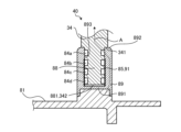
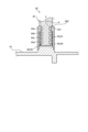
- FIG. 2 is an enlarged view of the electrical connection portion of the gas-insulated switchgear according to embodiment 1.
- the axial length of the rod-shaped conductor 88 is shorter than the axial length of the tubular conductor 89. Therefore, the step 341 of the movable-side outer conductor 34 abuts against the end 892 of the tubular conductor 89, and the tip 881 of the rod-shaped conductor 88 is not in contact with the bottom surface 891 of the tubular conductor 89.
- the tip 881 of the rod-shaped conductor 88 is also the tip 342 of the movable-side outer conductor 34.
- An insulating layer 85 is provided between a portion of the inner surface 893 of the tubular conductor 89 that is closer to the bottom surface 891 and the rod-shaped conductor 88.
- the insulating layer 85 is an insulating coating 91 formed on the inner surface 893 of the tubular conductor 89. As shown in FIG. 1, the bottom surface 891 is located closer to the opening/closing section 4 than the tubular conductor 89, so the insulating layer 85 can be considered to be provided on the portion of the inner surface 893 of the tubular conductor 89 that is closer to the opening/closing section 4.
- the ring-shaped conductors 84a, 84b, 84c, and 84d are fitted into each of the grooves of the rod-shaped conductor 88.
- the grooves in which the ring-shaped conductors 84a, 84b, 84c, and 84d are arranged are provided in the rod-shaped conductor 88 in the example described here, the grooves in which the ring-shaped conductors 84a, 84b, 84c, and 84d are arranged may be provided in the tubular conductor 89.
- the ring-shaped conductor 84a which is the furthest from the tip 881 of the rod-shaped conductor 88, is in contact with the tubular conductor 89, and the ring-shaped conductors 84b, 84c, and 84d, excluding the ring-shaped conductor 84a, are in contact with the insulating layer 85.
- the ring-shaped conductors 84b, 84c, and 84d that are in contact with the insulating layer 85 are the first ring-shaped conductors
- the ring-shaped conductor 84a is the second ring-shaped conductor that is positioned farther away from the opening/closing unit 4, which is the heat generating unit, than the first ring-shaped conductors 84b, 84c, and 84d.
- an insulating layer 85 is provided between a portion of the inner circumferential surface 893 of the tubular conductor 89 near the switching unit 4 and the rod-shaped conductor 88, and since no current flows through the first ring-shaped conductors 84b, 84c, and 84d, the current path of the main current between the movable contact 5a and the movable outer conductor 34 is the conductor rod 14, the contact 33, the main body 81, the tubular conductor 89, and the second ring-shaped conductor, ring-shaped conductor 84a. That is, as shown by the arrow A in FIG. 2, the main current passes only through the ring-shaped conductor 84a, and does not pass through the ring-shaped conductors 84b, 84c, and 84d.
- heat generated in the switching unit 4 is transferred to the rod-shaped conductor 88 via the conductor rod 14, the contact 33, the main body 81, the tubular conductor 89, and the ring-shaped conductors 84b, 84c, and 84d.
- the ring-shaped conductor 84a which is the current path, is located the furthest from the switching unit 4, which is the heat generating part, and is therefore least susceptible to the effects of heat from the switching unit 4.
- an insulating layer 85 is provided between a portion of the inner circumferential surface 893 of the cylindrical conductor 89 that is closer to the switchgear 4 and the rod-shaped conductor 88, and the ring-shaped conductors 84b, 84c, and 84d that are installed near the switchgear 4, which is a heat generating part, do not form a current path. Therefore, even if the temperature of the ring-shaped conductors 84b, 84c, and 84d that are installed near the switchgear 4, which is a heat generating part, rises, it does not affect the magnitude of the main current flowing in the current path.
- the ring-shaped conductor 84a which is installed farthest from the heat source, becomes the current path of the main current. Therefore, the temperature of the ring-shaped conductor 84a, which becomes the current path, is lower than that of the closer ring-shaped conductors 84b, 84c, and 84d, which are installed closer to the heat source.
- the heat dissipation area for dissipating heat from the ring-shaped conductor 84a, which is the current path of the main current, to below the design upper limit temperature is smaller than the heat dissipation area for dissipating heat from the ring-shaped conductors 84b, 84c, and 84d, which are not current paths of the main current, to below the design upper limit temperature. Therefore, in the gas-insulated switchgear 50 according to the first embodiment, the contact case 8 can be made smaller, so that the inner diameter of the ground tank 1, which is required for electrical insulation, is reduced, and the size of the equipment can be reduced.
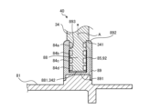
- Embodiment 2. 3 is an enlarged view of an electrical connection portion of a gas-insulated switchgear according to embodiment 2.
- the gas-insulated switchgear 50 according to embodiment 2 is similar to the gas-insulated switchgear 50 according to embodiment 1 except for the electrical connection portion 40.
- an insulating thin plate 92 is disposed between a part of an inner peripheral surface 893 of a cylindrical conductor 89 near a switching unit 4 (not shown in FIG. 3) and a rod-shaped conductor 88, and the insulating thin plate 92 forms an insulating layer 85.
- the configuration of the other portions is similar to that of the electrical connection portion 40 of the gas-insulated switchgear 50 according to embodiment 1.
- an insulating thin plate 92 arranged between a portion of the inner circumferential surface 893 of the tubular conductor 89 near the switching unit 4 (not shown in FIG. 3) and the rod-shaped conductor 88 forms an insulating layer 85, and since no current flows through the first ring-shaped conductors 84b, 84c, and 84d, the current path of the main current between the movable contact 5a and the movable outer conductor 34 is the conductor rod 14, the contact 33, the main body 81, the tubular conductor 89, and the second ring-shaped conductor, ring-shaped conductor 84a. That is, as shown by arrow A in FIG. 3, the main current passes only through the ring-shaped conductor 84a, and does not pass through the ring-shaped conductors 84b, 84c, and 84d.
- the heat generating part that generates heat when current is applied is the switchgear 4. Therefore, the heat generated in the switchgear 4 is transferred to the movable outer conductor 34 via the conductor rod 14, the contact 33, the main body 81, the tubular conductor 89, and the ring-shaped conductors 84b, 84c, and 84d.
- the ring-shaped conductor 84a which forms the current path, is located the farthest from the switchgear 4, which is the heat generating part, and is therefore least susceptible to the effects of heat from the switchgear 4.
- an insulating thin plate 92 arranged between a portion of the inner circumferential surface 893 of the cylindrical conductor 89 near the opening/closing unit 4 (not shown in FIG. 3) and the rod-shaped conductor 88 forms an insulating layer 85, and the ring-shaped conductors 84b, 84c, and 84d installed near the opening/closing unit 4, which is a heat generating part, do not form a current path.
- the ring-shaped conductor 84a installed farthest from the heat source becomes the current path of the main current, so the heat dissipation area for dissipating heat from the ring-shaped conductor 84a, which is the current path of the main current, to below the design upper limit temperature is smaller than the heat dissipation area for dissipating heat from the ring-shaped conductors 84b, 84c, and 84d, which are not current paths of the main current, to below the design upper limit temperature. Therefore, in the gas-insulated switchgear 50 according to the second embodiment, the contact case 8 can be made smaller, so the inner diameter of the ground tank 1 required for electrical insulation is smaller, making it possible to reduce the size of the equipment.
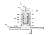
- Embodiment 3. 4 is an enlarged view of an electrical connection portion of a gas-insulated switchgear according to embodiment 3.
- the gas-insulated switchgear 50 according to embodiment 3 is similar to the gas-insulated switchgear 50 according to embodiment 1 except for the electrical connection portion 40.
- an insulating coating 94 provided on the portion of the ring-shaped conductors 84b, 84c, 84d that contacts the rod-shaped conductor 88 forms an insulating layer 85.
- the configuration of the other portions is similar to that of the electrical connection portion 40 of the gas-insulated switchgear 50 according to embodiment 1.
- the insulating coating 94 provided on the portions of the ring-shaped conductors 84b, 84c, and 84d that contact the rod-shaped conductor 88 forms the insulating layer 85, and since no current flows through the first ring-shaped conductors 84b, 84c, and 84d, the current path of the main current between the movable side contactor 5a and the movable side outer conductor 34 is the conductor rod 14, the contact 33, the main body 81, the tubular conductor 89, and the second ring-shaped conductor, ring-shaped conductor 84a. That is, as shown by the arrow A in FIG. 4, the main current passes only through the ring-shaped conductor 84a, and does not pass through the ring-shaped conductors 84b, 84c, and 84d.
- the heat generating part that generates heat when current is applied in the gas-insulated switchgear 50 according to the third embodiment is the switchgear 4. Therefore, the heat generated in the switchgear 4 is transferred to the movable outer conductor 34 via the conductor rod 14, the contact 33, the main body 81, the tubular conductor 89, and the ring-shaped conductors 84a, 84b, 84c, and 84d.
- the ring-shaped conductor 84a which forms the current path, is located the furthest from the switchgear 4, which is the heat generating part, and is therefore least susceptible to the effects of heat from the switchgear 4.
- the insulating coating 94 provided on the portions of the ring-shaped conductors 84b, 84c, and 84d that are in contact with the movable outer conductor 34 forms an insulating layer 85, and the ring-shaped conductors 84b, 84c, and 84d installed near the switchgear 4, which is a heat generating part, do not form a current path. Therefore, even if the temperature of the ring-shaped conductors 84b, 84c, and 84d installed near the switchgear 4, which is a heat generating part, rises, it does not affect the magnitude of the main current flowing in the current path.
- the ring-shaped conductor 84a installed farthest from the heat source becomes the current path of the main current, so the heat dissipation area for dissipating heat from the ring-shaped conductor 84a, which is the current path of the main current, to below the design upper limit temperature is smaller than the heat dissipation area for dissipating heat from the ring-shaped conductors 84b, 84c, and 84d, which are not current paths of the main current, to below the design upper limit temperature. Therefore, in the gas-insulated switchgear 50 according to the third embodiment, the contact case 8 can be made smaller, so the inner diameter of the ground tank 1 required for electrical insulation is smaller, making it possible to reduce the size of the equipment.
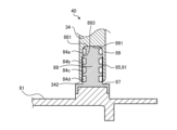
- Embodiment 4. 5 is an enlarged view of an electrical connection part of a gas-insulated switchgear according to embodiment 4.
- the gas-insulated switchgear 50 according to embodiment 4 is similar to the gas-insulated switchgear 50 according to embodiment 1 except for the electrical connection part 40.
- a hole extending in the axial direction is formed in the tip 342 of the movable-side outer conductor 34, and the tip part of the movable-side outer conductor 34 is a cylindrical conductor 89.
- the contact case 8 includes a rod-shaped conductor 88 extending in the outer circumferential direction of the main body 81 and a support part 87 that fixes the rod-shaped conductor 88 to the main body 81.
- the axial length of the rod-shaped conductor 88 is longer than the axial length of the cylindrical conductor 89. Therefore, the tip 881 of the rod-shaped conductor 88 abuts against the bottom surface 891 of the cylindrical conductor 89, and the tip 342 of the movable-side outer conductor 34 is not in contact with the support part 87.
- An insulating layer 85 is provided between the rod-shaped conductor 88 and a portion of the inner surface 893 of the cylindrical conductor 89 near the opening/closing unit 4 (not shown in FIG. 5) that generates heat when electricity is passed through it.
- the insulating layer 85 is an insulating coating 91 formed on the inner surface 893 of the cylindrical conductor 89.
- the ring-shaped conductors 84a, 84b, 84c, and 84d are fitted into each of the grooves of the rod-shaped conductor 88.
- the grooves in which the ring-shaped conductors 84a, 84b, 84c, and 84d are arranged are provided in the rod-shaped conductor 88 in the example described here, the grooves in which the ring-shaped conductors 84a, 84b, 84c, and 84d are arranged may be provided in the tubular conductor 89.
- the ring-shaped conductor 84a which is the furthest from the opening/closing portion 4, is in contact with the tubular conductor 89, and the ring-shaped conductors 84b, 84c, and 84d, excluding the ring-shaped conductor 84a, are in contact with the insulating layer 85.
- the ring-shaped conductors 84b, 84c, and 84d that are in contact with the insulating layer 85 are the first ring-shaped conductors
- the ring-shaped conductor 84a is the second ring-shaped conductor that is positioned farther away from the opening/closing unit 4, which is the heat generating unit, than the first ring-shaped conductors 84b, 84c, and 84d.
- an insulating layer 85 is provided between a portion of the inner circumferential surface 893 of the cylindrical conductor 89 near the switching unit 4 (not shown in FIG. 5) and the rod-shaped conductor 88, and the ring-shaped conductors 84b, 84c, and 84d installed near the switching unit 4 do not form a current path. Therefore, even if the temperature of the ring-shaped conductors 84b, 84c, and 84d installed near the switching unit 4, which is a heat generating part, rises, it does not affect the magnitude of the main current flowing in the current path.
- the ring-shaped conductor 84a which is installed farthest from the heat source, becomes the current path of the main current. Therefore, the temperature of the ring-shaped conductor 84a, which becomes the current path, is lower than that of the closer ring-shaped conductors 84b, 84c, and 84d, which are installed closer to the heat source.
- the heat dissipation area for dissipating heat from the ring-shaped conductor 84a, which is the current path of the main current, to below the design upper limit temperature is smaller than the heat dissipation area for dissipating heat from the ring-shaped conductors 84b, 84c, and 84d, which are not current paths of the main current, to below the design upper limit temperature. Therefore, in the gas-insulated switchgear 50 according to the fourth embodiment, the contact case 8 can be made smaller, so that the inner diameter of the ground tank 1, which is required for electrical insulation, is smaller, and the size of the equipment can be reduced.
- Embodiment 5. 6 is an enlarged view of an electrical connection part of a gas-insulated switchgear according to embodiment 5.
- the gas-insulated switchgear 50 according to embodiment 5 is similar to the gas-insulated switchgear 50 according to embodiment 1 except for the electrical connection part 40.
- the electrical connection part 40 of the gas-insulated switchgear 50 according to embodiment 5 includes a first cylindrical conductor 95 which is a part of the cylindrical conductor 89, and a second cylindrical conductor 96 which is a part of the cylindrical conductor 89.
- the second cylindrical conductor 96 is a cylindrical conductor that is thinner and shorter than the first cylindrical conductor 95, and is installed in the first cylindrical conductor 95, closer to the main body 81. Note that the opening/closing part 4, not shown in FIG.
- the first tubular conductor 95 is in contact with the main body portion 81 , but the second tubular conductor 96 is not in contact with the main body portion 81 .
- An insulating layer 85 is provided between the first tubular conductor 95 and the second tubular conductor 96.
- the insulating layer 85 is an insulating coating 91 formed on at least one of the portion of the first tubular conductor 95 that contacts the second tubular conductor 96 and the portion of the second tubular conductor 96 that contacts the first tubular conductor 95.
- the ring-shaped conductors 84a, 84b, 84c, and 84d are fitted into each of the grooves of the movable side outer conductor 34.
- the grooves in which the ring-shaped conductors 84a, 84b, 84c, and 84d are arranged are provided in the movable side outer conductor 34
- the grooves in which the ring-shaped conductors 84a, 84b, 84c, and 84d are arranged may also be provided in the first tubular conductor 95 and the second tubular conductor 96.
- the ring-shaped conductor 84a which is the furthest from the lower end of the movable-side outer conductor 34, is in contact with the first cylindrical conductor 95, and the ring-shaped conductors 84b, 84c, and 84d, excluding the ring-shaped conductor 84a, are in contact with the second cylindrical conductor 96.
- an insulating layer 85 is provided between the first tubular conductor 95 and the second tubular conductor 96, and since no current flows between the first tubular conductor 95 and the second tubular conductor 96, the main current path between the movable contact 5a and the movable outer conductor 34 is the conductor rod 14, the contact 33, the main body 81, the first tubular conductor 95, and the ring-shaped conductor 84a. As shown by the arrow A in FIG. 6, the main current passes only through the ring-shaped conductor 84a, and does not pass through the ring-shaped conductors 84b, 84c, and 84d.
- an insulating layer 85 is provided between the first cylindrical conductor 95 and the second cylindrical conductor 96, and similarly to the gas-insulated switchgear 50 according to the first embodiment, the ring-shaped conductors 84b, 84c, and 84d installed near the switchgear 4, which is a heat generating part, do not form a current path. Therefore, even if the temperature of the ring-shaped conductors 84b, 84c, and 84d installed near the switchgear 4, which is a heat generating part, rises, it does not affect the magnitude of the main current flowing in the current path.
- the ring-shaped conductor 84a which is installed farthest from the heat source, becomes the current path of the main current. Therefore, the temperature of the ring-shaped conductor 84a, which becomes the current path, is lower than that of the ring-shaped conductors 84b, 84c, and 84d, which are installed closer to the heat source.
- the heat dissipation area for dissipating heat from the ring-shaped conductor 84a, which is the current path of the main current, to below the design upper limit temperature is smaller than the heat dissipation area for dissipating heat from the ring-shaped conductors 84b, 84c, and 84d, which are not current paths of the main current, to below the design upper limit temperature. Therefore, in the gas-insulated switchgear 50 according to the fifth embodiment, the contact case 8 can be made smaller, so that the inner diameter of the ground tank 1, which is required for electrical insulation, is smaller, and the size of the equipment can be reduced.
Landscapes
- Engineering & Computer Science (AREA)
- Power Engineering (AREA)
- Gas-Insulated Switchgears (AREA)
- Installation Of Bus-Bars (AREA)
- Circuit Breakers (AREA)
Abstract
La présente invention concerne un dispositif d'ouverture et de fermeture à isolation gazeuse qui comprend : une partie d'émission de chaleur qui émet de la chaleur lorsqu'elle est électrifiée par un courant électrique principal; et une partie de connexion électrique (40) qui constitue une connexion électrique avec un conducteur en forme de tige et un conducteur cylindrique qui forment un trajet d'électrification pour le courant électrique principal, la partie de connexion électrique (40) ayant une pluralité de conducteurs en forme d'anneau (84a, 84b, 84c, 84d) qui sont agencés entre le conducteur en forme de tige (88) et le conducteur cylindrique (89), la pluralité de conducteurs en forme d'anneau (84a, 84b, 84c, 84d) comprenant des premiers conducteurs en forme d'anneau (84b, 84c, 84d) et un second conducteur en forme d'anneau (84a) qui est positionné à une position qui est plus éloignée de la partie d'émission de chaleur que les premiers conducteurs en forme d'anneau (84b, 84c, 84d), et une couche isolante (85) étant disposée entre les premiers conducteurs en forme d'anneau (84b, 84c, 84d) et le conducteur cylindrique (89), ou entre chacun des premiers conducteurs en forme d'anneau (84b, 84c, 84d) et le conducteur en forme de tige (88).
Priority Applications (3)
| Application Number | Priority Date | Filing Date | Title |
|---|---|---|---|
| EP23921170.9A EP4664696A1 (fr) | 2023-02-10 | 2023-02-10 | Appareillage à isolation gazeuse |
| PCT/JP2023/004485 WO2024166340A1 (fr) | 2023-02-10 | 2023-02-10 | Appareillage à isolation gazeuse |
| JP2023540838A JP7412650B1 (ja) | 2023-02-10 | 2023-02-10 | ガス絶縁機器 |
Applications Claiming Priority (1)
| Application Number | Priority Date | Filing Date | Title |
|---|---|---|---|
| PCT/JP2023/004485 WO2024166340A1 (fr) | 2023-02-10 | 2023-02-10 | Appareillage à isolation gazeuse |
Publications (1)
| Publication Number | Publication Date |
|---|---|
| WO2024166340A1 true WO2024166340A1 (fr) | 2024-08-15 |
Family
ID=89451981
Family Applications (1)
| Application Number | Title | Priority Date | Filing Date |
|---|---|---|---|
| PCT/JP2023/004485 Ceased WO2024166340A1 (fr) | 2023-02-10 | 2023-02-10 | Appareillage à isolation gazeuse |
Country Status (3)
| Country | Link |
|---|---|
| EP (1) | EP4664696A1 (fr) |
| JP (1) | JP7412650B1 (fr) |
| WO (1) | WO2024166340A1 (fr) |
Citations (3)
| Publication number | Priority date | Publication date | Assignee | Title |
|---|---|---|---|---|
| JPH0417607U (fr) * | 1990-05-31 | 1992-02-13 | ||
| JP2017227329A (ja) | 2016-06-15 | 2017-12-28 | 住友化学株式会社 | 積層体およびその製造方法 |
| JP7090825B1 (ja) * | 2021-09-28 | 2022-06-24 | 三菱電機株式会社 | タンク型遮断器 |
-
2023
- 2023-02-10 JP JP2023540838A patent/JP7412650B1/ja active Active
- 2023-02-10 EP EP23921170.9A patent/EP4664696A1/fr active Pending
- 2023-02-10 WO PCT/JP2023/004485 patent/WO2024166340A1/fr not_active Ceased
Patent Citations (3)
| Publication number | Priority date | Publication date | Assignee | Title |
|---|---|---|---|---|
| JPH0417607U (fr) * | 1990-05-31 | 1992-02-13 | ||
| JP2017227329A (ja) | 2016-06-15 | 2017-12-28 | 住友化学株式会社 | 積層体およびその製造方法 |
| JP7090825B1 (ja) * | 2021-09-28 | 2022-06-24 | 三菱電機株式会社 | タンク型遮断器 |
Also Published As
| Publication number | Publication date |
|---|---|
| EP4664696A1 (fr) | 2025-12-17 |
| JP7412650B1 (ja) | 2024-01-12 |
| JPWO2024166340A1 (fr) | 2024-08-15 |
Similar Documents
| Publication | Publication Date | Title |
|---|---|---|
| CN103109339B (zh) | 用于受限制的两个接触电极的断路器管开关装置 | |
| US9330868B2 (en) | Contact assembly for a vacuum circuit breaker | |
| CN103026564B (zh) | 气体绝缘电气设备 | |
| CN103703533B (zh) | 气体断路器 | |
| JP5060328B2 (ja) | 真空スイッチギヤ | |
| US11348748B2 (en) | Switch device | |
| WO2024166340A1 (fr) | Appareillage à isolation gazeuse | |
| ZA201003154B (en) | Electrical conductor for a high-current bushing | |
| CN101233593A (zh) | 电开关装置以及运行电开关装置的方法 | |
| CN105529209A (zh) | 用于真空断续器的轴向磁场线圈 | |
| CN101288141B (zh) | 具有防燃弧的短路电流引导装置的高功率开关 | |
| EA001575B1 (ru) | Дугогасительная камера для высоковольтного выключателя | |
| JP6245972B2 (ja) | 真空バルブおよびそれを用いた開閉器 | |
| CN101728119A (zh) | 用于高压开关的消弧室以及高压开关 | |
| CN102005328B (zh) | 一种气体绝缘负荷开关的旋弧式灭弧装置 | |
| JP7608296B2 (ja) | ガス絶縁開閉装置 | |
| CN109314010A (zh) | 具有双导电壳体的开关装置 | |
| US20150114933A1 (en) | Pushrod assembly for a medium voltage vacuum circuit breaker | |
| CN112164620A (zh) | 一种真空灭弧室结构 | |
| CN203277206U (zh) | 户外真空断路器 | |
| EP4693359A1 (fr) | Contrôleur de champ électrique pour interrupteur à vide, et interrupteur à vide | |
| CN113284760B (zh) | 一种带有可动屏蔽罩结构的真空灭弧室 | |
| JP2007188661A (ja) | 真空バルブ | |
| JP5525364B2 (ja) | 真空バルブ | |
| JP2910162B2 (ja) | ガス遮断器 |
Legal Events
| Date | Code | Title | Description |
|---|---|---|---|
| WWE | Wipo information: entry into national phase |
Ref document number: 2023540838 Country of ref document: JP |
|
| 121 | Ep: the epo has been informed by wipo that ep was designated in this application |
Ref document number: 23921170 Country of ref document: EP Kind code of ref document: A1 |
|
| NENP | Non-entry into the national phase |
Ref country code: DE |
|
| WWP | Wipo information: published in national office |
Ref document number: 2023921170 Country of ref document: EP |