WO2024166287A1 - 機械 - Google Patents
機械 Download PDFInfo
- Publication number
- WO2024166287A1 WO2024166287A1 PCT/JP2023/004350 JP2023004350W WO2024166287A1 WO 2024166287 A1 WO2024166287 A1 WO 2024166287A1 JP 2023004350 W JP2023004350 W JP 2023004350W WO 2024166287 A1 WO2024166287 A1 WO 2024166287A1
- Authority
- WO
- WIPO (PCT)
- Prior art keywords
- actuator
- machine
- actuators
- wire
- wiring
- Prior art date
- Legal status (The legal status is an assumption and is not a legal conclusion. Google has not performed a legal analysis and makes no representation as to the accuracy of the status listed.)
- Ceased
Links
Images






Classifications
-
- B—PERFORMING OPERATIONS; TRANSPORTING
- B25—HAND TOOLS; PORTABLE POWER-DRIVEN TOOLS; MANIPULATORS
- B25J—MANIPULATORS; CHAMBERS PROVIDED WITH MANIPULATION DEVICES
- B25J19/00—Accessories fitted to manipulators, e.g. for monitoring, for viewing; Safety devices combined with or specially adapted for use in connection with manipulators
- B25J19/0025—Means for supplying energy to the end effector
- B25J19/0029—Means for supplying energy to the end effector arranged within the different robot elements
Definitions
- This disclosure relates to a machine.
- Each of the multiple actuators includes a motor, an amplifier, and the like.
- the multiple actuators or the amplifiers of the multiple actuators are connected to each other via a bus connection or a daisy chain connection. This allows current from an external power source to be supplied to each of the multiple actuators (see, for example, JP 2015-093329 A).
- each actuator requires both an input terminal and an output terminal.
- the actuator board area becomes larger, and the actuator becomes larger. This means that machines equipped with multiple actuators also become larger.
- the actuator in the case of bus connection, it is sufficient for the actuator to have one terminal.
- soldering or branching work using a branch connector is required. This reduces the reliability of a machine equipped with multiple actuators, and also requires space to perform the branching work. This causes the problem of the machine becoming larger.
- a machine includes a first actuator and a second actuator, a first wire that connects an external power source to the first actuator, a first wiring section provided on the first wire, and a second wire that connects the second actuator to the first wiring section.
- FIG. 1 is a perspective view of an exemplary machine of the present disclosure.
- FIG. 2 is a block diagram of a machine according to a first embodiment.
- FIG. 2 is a block diagram of a machine according to a first variant of the first embodiment.
- FIG. 11 is a block diagram of a machine according to a second variant of the first embodiment.
- FIG. 11 is a block diagram of a machine according to a third variant of the first embodiment.
- FIG. 11 is a block diagram of a machine according to a variant of the second embodiment.
- FIG. 2C is a view similar to FIG. 2B.
- FIG. 4 is a view similar to FIG.
- FIG. 2 is a view similar to FIG.
- FIG. 1 is a block diagram of a machine in the prior art.
- FIG. 1 is a block diagram of another machine in the prior art.
- FIG. 1 is a perspective view showing a typical machine of the present disclosure.
- the machine 1 shown in FIG. 1 is a robot 1, for example, a six-axis vertical articulated robot.
- the robot 1 is equipped with a plurality of actuators, for example, six actuators 5a-5f.
- the actuators 5a-5f are arranged at each of the joint axes of the robot 1. These actuators 5a-5f are arranged in order from the base of the robot 1 toward the tip of the robot 1.
- an external power source 10 shown in FIG. 1 supplies current to the plurality of actuators 5a-5f of the machine 1, thereby driving the machine 1.
- the machine 1 will be described as a robot. However, the machine 1 only needs to be equipped with two or more actuators, and does not necessarily have to be equipped with six actuators. The machine 1 may also be another machine equipped with multiple actuators, such as a machine tool.
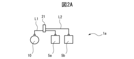
- FIG. 2A is a block diagram of a machine based on the first embodiment.
- the machine 1a shown in FIG. 2A has two actuators 5a and 5b.
- Each of the actuators 5a to 5f includes a motor, a reducer, an amplifier, etc., but these are not shown for the sake of simplicity. The same applies to the other actuators 5c to 5f described below.
- the first actuator 5a of the machine 1a and the external power source 10 are connected to each other by a first wire L1.
- the first wire L1 is, for example, a power bus or a power cable.
- a first wiring section 21 is provided between the first actuator 5a and the external power source 10.
- the first wiring section 21 is a wiring section that branches the first wire L1, which supplies current, to at least one other wire.
- the first wiring section 21 can be, for example, a terminal block with multiple terminals.
- the second wire L2 extends from the first wiring section 21 and is connected to the second actuator 5b.
- the first actuator 5a it is sufficient for the first actuator 5a to have a single connector to be connected to the first wire L1.
- the second actuator 5b it is sufficient for the second actuator 5b to have a single connector to be connected to the second wire L2.
- the actuators 5a and 5b do not need to have multiple terminals, such as an input terminal and an output terminal, and as a result, the actuators 5a and 5b can be made in a space-saving manner. This also allows the machine 1a including the actuators 5a and 5b to be space-saving.
- the second wire L2 is connected using the first wiring portion 21.
- the second wire L2 is connected using the first wiring portion 21.
- FIG. 6A is a block diagram of a machine in the prior art.
- FIG. 6A shows a machine 1' equipped with multiple actuators 5a'-5f'.
- Each of the multiple actuators 5a'-5f' is daisy-chain connected. For this reason, each actuator 5a'-5f' requires an input terminal and an output terminal.
- the prior art had the problem that each actuator 5a'-5f' and the machine 1' became large in size.
- FIG. 6B is a block diagram of a machine in the prior art.
- FIG. 6B shows a machine 1'' equipped with multiple actuators 5a''-5f''.
- a wire L'' is connected to an external power source 10.
- Each of the multiple actuators 5a''-5f'' is bus-connected to the wire L''. For this reason, soldering or branching processing using a branch connector was required to connect each of the multiple actuators 5a''-5f'' to the wire L''. This could result in a decrease in the reliability of the machine 1''.
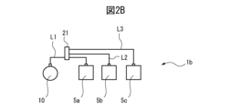
- FIG. 2B is a block diagram of a machine based on a first modified example of the first embodiment.
- Machine 1b shown in FIG. 2B includes three actuators 5a to 5c.
- Second and third wires L2 and L3 are connected to first wiring section 21.
- Third wires L3 are connected to third actuator 5c. In this manner, multiple wires L2 and L3 may be connected to first wiring section 21, and the same effect as described above can be obtained.
- FIG. 2C is a block diagram of a machine based on a second modified example of the first embodiment.
- the machine 1c shown in FIG. 2C includes four actuators 5a-5d.
- a second wiring section 22 is provided on the filament L2.
- the second wiring section 22 has a similar configuration to the first wiring section 21, and is a section that wires the filament L2 so that it branches out to at least one other filament.
- the second wiring section 22 is provided on the filament L2 connected to the first wiring section 21, whereas the first wiring section 21 is provided on the first filament L1 connected to the external power source 10.
- a third wire L3 and a fourth wire L4 extend from the second wiring portion 22.
- the third wire L3 is connected to the third actuator 5c, and the fourth wire L4 is connected to the fourth actuator 5d.
- a configuration in which multiple wires L3 and L4 are connected to the second wiring portion 22 may be used, and in this case as well, the same effect as described above can be obtained.
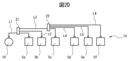
- FIG. 2D is a block diagram of a machine based on a third modified example of the first embodiment.
- the machine 1d shown in FIG. 2D includes five actuators 5a to 5e.
- the second wiring section 22 is provided on the third umbilical member L3.
- a fourth umbilical member L4 and a fifth umbilical member L5 extend further from the second wiring section 22.
- the fourth umbilical member L4 is connected to the fourth actuator 5d
- the fifth umbilical member L5 is connected to the fifth actuator 5f.
- a configuration in which multiple umbilical members L3, L4, and L5 are connected to the second wiring section 22 may be used, and the same effect as described above can be obtained.
- FIG. 3 is a block diagram of another machine based on the second embodiment.
- the machine 1f shown in FIG. 3 includes six actuators 5a to 5f.
- a plurality of filaments L2, L3 are connected to a first wiring section 21 provided on a first filament L1.
- a plurality of filaments L4 to L6 are further connected to a second wiring section 22 provided on a third filament L3.
- the plurality of filaments L4 to L6 are respectively connected to a fourth actuator 5d to a sixth actuator 5f.
- a plurality of filaments L2, L3 are connected to a single first wiring section 21 and a plurality of filaments L4 to L6 are connected to a single second wiring section 22 is also included in the scope of the present disclosure.
- FIG. 4A is a diagram similar to FIG. 2B.
- the first wire body L1 in the machine 1e shown in FIG. 4A is divided into a first wire body portion L1a located between the external power source 10 and the first wiring section 21, and a first wire body portion L1b located between the first wiring section 21 and the first actuator 5a.
- the first wire body portion L1a is thicker than the first wire body portion L1b.
- FIG. 4A shows region A located between the first wiring portion 21 and the first actuator 5a.
- the first filament portion L1b and two filaments L2, L3 are present.
- the thickness of the two filaments L2, L3 is approximately equal to the thickness of the first filament portion L1b.
- the first filament portion L1a of the first filament L1 is thick enough to supply the current required for the three actuators 5a to 5c.
- the first filament portion L1b and the two filaments L2 and L3 only need to be thick enough to supply the current required for the corresponding single actuator.
- the total thickness of these need only be approximately the same as that of the first filament portion L1a.
- the total number of filament portions L1b and filaments L2 and L3 in region A is large, no additional space is required in region A. This is similar in other embodiments and other modified examples, and it is possible to reduce the thickness of each filament (and filament portion) in a region where multiple filaments (and filament portions) are present, as described above.
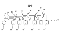
- FIG. 4B is a diagram similar to FIG. 3.
- the wires L2 and L3 are fixed by a relay connector R1.
- the wires L4 to L6 are fixed by a relay connector R2.
- the wires L5 and L6 are fixed by a relay connector R3.
- a certain actuator for example actuator 5c
- the next actuator for example actuator 5d
- a relay connector for example relay connector R2 fixes a number of wires, for example wires L4, L5, and L6, between a certain actuator, for example actuator 5c, and the next actuator, for example actuator 5d.
- relay connectors R1 to R3 bundle the multiple wires together inside machine 1f, thereby preventing the multiple wires from being exposed to the outside of machine 1f and facilitating wiring work inside machine 1f.
- the wire L6 may be fixed by a relay connector R4.
- another wire for example a wire for operating an end effector (not shown) located closer to the tip of the robot than the sixth actuator 5f, may be fixed by the relay connector R4. In this case as well, the same effect as described above can be obtained.
- FIG. 5 is a diagram similar to FIG. 1.
- the six-axis vertical articulated robot 1f shown in FIG. 5 includes a first arm member 11 extending vertically relative to a base member BA and rotatable about a first axis, a second arm member 12 supported rotatably about a second axis extending horizontally relative to the first arm member 11, a third arm member 13 supported rotatably about a third axis extending horizontally at the tip side of the second arm member 12, a fourth arm member 14 supported by the third arm member 13 rotatably about a fourth axis extending in the extension direction of the third arm member 13, a fifth arm member 15 supported by the fourth arm member 14 rotatably about a fifth axis extending in a direction perpendicular to the fourth axis, and a sixth arm member 16 supported by the fifth arm member 15 rotatably about a sixth axis.
- Each of the first to sixth axes is perpendicular to the other adjacent axes.
- the first to sixth actuators 5a to 5f are arranged inside the robot 1f in correspondence with the first to sixth axes, respectively.
- a first group 51 is shown, which is made up of three or more actuators, 5a-5c.
- a first wire L1 connects the external power source 10 to one of the actuators in the first group 51, 5a.
- a first wiring section 21 is also disposed on the first wire L1.
- the remaining actuators 5b and 5c in the first group 51, excluding the aforementioned one actuator 5a, are connected to the first wiring section 21 by wires L2 and L3, respectively.
- FIG. 3 shows a second set 52 consisting of at least one actuator 5d-5f.
- the second wiring portion 22 is provided on the third wire body L3.
- at least one additional wire body L4-L6 is arranged to connect at least one actuator 5d-5f in the second set 52 to the second wiring portion 22.
- wiring units 21, 22 and filaments L1-L6 are arranged on robot 1f based on the configuration in FIG. 3.
- first wiring unit 21 is arranged near first arm member 11 of robot 1f, and can also be mounted inside first arm member 11. Furthermore, first arm member 11 is located on the base end side of robot 1f. Sixth arm member 16 of machine 1f almost never moves near first arm member 11, and therefore there are no space issues with first wiring unit 21.
- the second wiring part 22 is disposed inside the second arm member 12 which is rotatably connected to the first arm member 11. Therefore, the presence of the second wiring part 22 does not change the external shape of the robot 1f, for example, the external shape of the second arm member 12. Therefore, there are no space problems with respect to the second wiring part 22.
- each of the groups 51, 52 is equipped with wiring units 21, 22.
- the reason for this is that by arranging the wiring units 21, 22 in a location in the machine 1f where there is ample space, it is possible to avoid the machine 1f becoming larger. Therefore, it is particularly advantageous to apply the configuration shown in Figure 3 to a 6-axis vertical articulated robot 1f as shown in Figure 5.
- the effect of at least one of the embodiments described above is that the actuator only needs to be provided with a single terminal, and therefore the actuator and the machine do not need to be made larger.
- a space-saving machine consisting of multiple actuators with only one terminal can be provided.
- soldering or branching processing using a branch connector is no longer necessary, which can increase the reliability of the machine.
- (Appendix 1) A first actuator and a second actuator; A first umbilical member that connects an external power source and the first actuator; A first wiring portion provided on the first filament; a second wire member connecting the second actuator and the first wiring portion.
- (Appendix 2) A third actuator; and 2.
- (Appendix 3) At least one additional actuator; A second wiring portion provided on the second filament; 2.
- (Appendix 4) At least one additional actuator; A second wiring portion provided on the third filament; 3.
- the machine of claim 2 further comprising at least one additional wire connecting the at least one additional actuator and the second wiring portion.
- Appendix 5 a first set of three or more actuators; a first umbilical member connecting an external power source to one of the first set of actuators; A first wiring portion provided on the first filament; at least one additional wire connecting at least one remaining actuator of the first set, excluding the one actuator, to the first wiring portion.
- Appendix 6) a second set of at least one actuator; A single second wiring portion provided in the at least one second filament; 6.
Landscapes
- Engineering & Computer Science (AREA)
- Robotics (AREA)
- Mechanical Engineering (AREA)
- Manipulator (AREA)
- Linear Motors (AREA)
Abstract
Description
図1は本開示の典型的な機械を示す斜視図である。図1に示される機械1は、ロボット1、例えば6軸垂直多関節ロボットである。ロボット1は、複数、例えば6個のアクチュエータ5a~5fを備えている。公知であるように、アクチュエータ5a~5fはロボット1の関節軸のそれぞれに配置されている。これらアクチュエータ5a~5fはロボット1の基部からロボット1の先端に向かって順番に配置されている。なお、図1に示される外部電源10は機械1の複数のアクチュエータ5a~5fに電流を供給し、それにより、機械1を駆動させる。
(付記1)
第一アクチュエータおよび第二アクチュエータと、
外部電源と前記第一アクチュエータとを接続する第一線条体と、
該第一線条体に備えられた第一配線部と、
前記第二アクチュエータと前記第一配線部とを接続する第二線条体と、を具備する、機械。
(付記2)
第三アクチュエータと、
該第三アクチュエータと前記第一配線部とを接続する第三線条体と、更に具備する、付記1に記載の機械。
(付記3)
少なくとも一つの追加アクチュエータと、
前記第二線条体に備えられた第二配線部と、
前記少なくとも一つの追加アクチュエータと前記第二配線部とを接続する少なくとも一つの追加線条体とを具備する、付記1に記載の機械。
(付記4)
少なくとも一つの追加アクチュエータと、
前記第三線条体に備えられた第二配線部と、
前記少なくとも一つの追加アクチュエータと前記第二配線部とを接続する少なくとも一つの追加線条体とを具備する、付記2に記載の機械。
(付記5)
三つ以上のアクチュエータからなる第一組と、
外部電源と前記第一組のうちの一つのアクチュエータとを接続する第一線条体と、
該第一線条体に備えられた第一配線部と、
前記一つのアクチュエータを除いた前記第一組の残りの少なくとも一つのアクチュエータと前記第一配線部とを接続する少なくとも一つの追加線条体と、を具備する、機械。
(付記6)
少なくとも一つのアクチュエータからなる第二組と、
前記少なくとも一つの第二線条体に備えられた単一の第二配線部と、
前記第二組における前記少なくとも一つのアクチュエータと前記第二配線部とを接続する少なくとも一つの追加線条体と、をさらに具備する付記5に記載の機械。
5c~5f アクチュエータ
11 ベース
11 第一アーム部材
12 第二アーム部材
13 第三アーム部材
14 第四アーム部材
15 第五アーム部材
16 第六アーム部材
21 第一配線部
22 第二配線部
51 第一組
52 第二組
L1~L6 線条体
L1a、L1b 第一線条体部分
R1~R3 中継コネクタ
Claims (6)
- 第一アクチュエータおよび第二アクチュエータと、
外部電源と前記第一アクチュエータとを接続する第一線条体と、
該第一線条体に備えられた第一配線部と、
前記第二アクチュエータと前記第一配線部とを接続する第二線条体と、を具備する、機械。 - 第三アクチュエータと、
該第三アクチュエータと前記第一配線部とを接続する第三線条体と、更に具備する、請求項1に記載の機械。 - 少なくとも一つの追加アクチュエータと、
前記第二線条体に備えられた第二配線部と、
前記少なくとも一つの追加アクチュエータと前記第二配線部とを接続する少なくとも一つの追加線条体とを具備する、請求項1に記載の機械。 - 少なくとも一つの追加アクチュエータと、
前記第三線条体に備えられた第二配線部と、
前記少なくとも一つの追加アクチュエータと前記第二配線部とを接続する少なくとも一つの追加線条体とを具備する、請求項2に記載の機械。 - 三つ以上のアクチュエータからなる第一組と、
外部電源と前記第一組のうちの一つのアクチュエータとを接続する第一線条体と、
該第一線条体に備えられた第一配線部と、
前記一つのアクチュエータを除いた前記第一組の残りの少なくとも一つのアクチュエータと前記第一配線部とを接続する少なくとも一つの追加線条体と、を具備する、機械。 - 少なくとも一つのアクチュエータからなる第二組と、
前記少なくとも一つの第二線条体に備えられた単一の第二配線部と、
前記第二組における前記少なくとも一つのアクチュエータと前記第二配線部とを接続する少なくとも一つの追加線条体と、をさらに具備する請求項5に記載の機械。
Priority Applications (6)
| Application Number | Priority Date | Filing Date | Title |
|---|---|---|---|
| DE112023004106.7T DE112023004106T5 (de) | 2023-02-09 | 2023-02-09 | Maschine |
| CN202380081670.8A CN120265438A (zh) | 2023-02-09 | 2023-02-09 | 机械 |
| JP2024575982A JPWO2024166287A1 (ja) | 2023-02-09 | 2023-02-09 | |
| PCT/JP2023/004350 WO2024166287A1 (ja) | 2023-02-09 | 2023-02-09 | 機械 |
| TW113100884A TW202432326A (zh) | 2023-02-09 | 2024-01-09 | 機械 |
| US19/194,501 US20250269545A1 (en) | 2023-02-09 | 2025-04-30 | Machine |
Applications Claiming Priority (1)
| Application Number | Priority Date | Filing Date | Title |
|---|---|---|---|
| PCT/JP2023/004350 WO2024166287A1 (ja) | 2023-02-09 | 2023-02-09 | 機械 |
Related Child Applications (1)
| Application Number | Title | Priority Date | Filing Date |
|---|---|---|---|
| US19/194,501 Continuation US20250269545A1 (en) | 2023-02-09 | 2025-04-30 | Machine |
Publications (1)
| Publication Number | Publication Date |
|---|---|
| WO2024166287A1 true WO2024166287A1 (ja) | 2024-08-15 |
Family
ID=92262224
Family Applications (1)
| Application Number | Title | Priority Date | Filing Date |
|---|---|---|---|
| PCT/JP2023/004350 Ceased WO2024166287A1 (ja) | 2023-02-09 | 2023-02-09 | 機械 |
Country Status (6)
| Country | Link |
|---|---|
| US (1) | US20250269545A1 (ja) |
| JP (1) | JPWO2024166287A1 (ja) |
| CN (1) | CN120265438A (ja) |
| DE (1) | DE112023004106T5 (ja) |
| TW (1) | TW202432326A (ja) |
| WO (1) | WO2024166287A1 (ja) |
Citations (4)
| Publication number | Priority date | Publication date | Assignee | Title |
|---|---|---|---|---|
| JP2002175103A (ja) * | 2000-12-06 | 2002-06-21 | Oriental Motor Co Ltd | モータ等の制御ユニットとデジタル通信路とを接続するコネクタ装置 |
| JP2005250924A (ja) * | 2004-03-05 | 2005-09-15 | Denso Corp | 製造設備 |
| JP2015013343A (ja) * | 2013-07-05 | 2015-01-22 | ファナック株式会社 | ロボット用駆動ケーブルの処理構造体及びそれを具備するロボット装置 |
| JP2017195038A (ja) * | 2016-04-18 | 2017-10-26 | オークラ輸送機株式会社 | 端子台取付装置および搬送装置 |
-
2023
- 2023-02-09 WO PCT/JP2023/004350 patent/WO2024166287A1/ja not_active Ceased
- 2023-02-09 DE DE112023004106.7T patent/DE112023004106T5/de active Pending
- 2023-02-09 CN CN202380081670.8A patent/CN120265438A/zh active Pending
- 2023-02-09 JP JP2024575982A patent/JPWO2024166287A1/ja active Pending
-
2024
- 2024-01-09 TW TW113100884A patent/TW202432326A/zh unknown
-
2025
- 2025-04-30 US US19/194,501 patent/US20250269545A1/en active Pending
Patent Citations (4)
| Publication number | Priority date | Publication date | Assignee | Title |
|---|---|---|---|---|
| JP2002175103A (ja) * | 2000-12-06 | 2002-06-21 | Oriental Motor Co Ltd | モータ等の制御ユニットとデジタル通信路とを接続するコネクタ装置 |
| JP2005250924A (ja) * | 2004-03-05 | 2005-09-15 | Denso Corp | 製造設備 |
| JP2015013343A (ja) * | 2013-07-05 | 2015-01-22 | ファナック株式会社 | ロボット用駆動ケーブルの処理構造体及びそれを具備するロボット装置 |
| JP2017195038A (ja) * | 2016-04-18 | 2017-10-26 | オークラ輸送機株式会社 | 端子台取付装置および搬送装置 |
Also Published As
| Publication number | Publication date |
|---|---|
| US20250269545A1 (en) | 2025-08-28 |
| TW202432326A (zh) | 2024-08-16 |
| CN120265438A (zh) | 2025-07-04 |
| JPWO2024166287A1 (ja) | 2024-08-15 |
| DE112023004106T5 (de) | 2025-08-07 |
Similar Documents
| Publication | Publication Date | Title |
|---|---|---|
| JP6245096B2 (ja) | ロボットおよびロボットシステム | |
| US9975239B2 (en) | Robot | |
| JP2008044019A (ja) | 産業用ロボットの手首駆動構造 | |
| CN105269590A (zh) | 机器人的关节机构以及机器人 | |
| TWI872233B (zh) | 協作機器人操作系統,協作機器人線管理系統,及用於固定操作經安裝於一協作機器人之一末端執行器上之工具之複數個撓性線之方法 | |
| CN105290566A (zh) | 机器人 | |
| JP2017047492A (ja) | 多関節マニピュレータ | |
| JPH07124887A (ja) | 産業用ロボットのケーブル処理装置 | |
| EP0909999A4 (en) | TRANSMISSION PROCEDURE FOR MACHINE CONTROL | |
| WO2024166287A1 (ja) | 機械 | |
| CN105291089A (zh) | 机器人 | |
| US20240383128A1 (en) | Industrial robot with cable wiring structure | |
| JP6962118B2 (ja) | ワーク搬送装置 | |
| CN104821526A (zh) | 工业机器人的线缆布置结构以及工业机器人 | |
| CN104440942A (zh) | 机器人 | |
| EP2781300A2 (en) | Workpiece assembly line and method for producing workpiece | |
| JP2003025270A (ja) | 産業用ロボットの配線配管処理装置 | |
| US12186901B2 (en) | Robot system | |
| JP2008091684A (ja) | サーボアンプおよび表面実装機 | |
| KR20230110608A (ko) | 다관절 작동 키네마틱 | |
| JP2011104773A (ja) | ワーク加工システム | |
| JP5939364B1 (ja) | 加工装置 | |
| TW202612862A (zh) | 多關節機器人 | |
| CN115298001A (zh) | 线缆束、线缆束的制造方法及具有线缆束的工业用机器人 | |
| US11956092B2 (en) | Communication system and connector |
Legal Events
| Date | Code | Title | Description |
|---|---|---|---|
| 121 | Ep: the epo has been informed by wipo that ep was designated in this application |
Ref document number: 23921118 Country of ref document: EP Kind code of ref document: A1 |
|
| WWE | Wipo information: entry into national phase |
Ref document number: 2024575982 Country of ref document: JP |
|
| WWE | Wipo information: entry into national phase |
Ref document number: 202380081670.8 Country of ref document: CN |
|
| WWE | Wipo information: entry into national phase |
Ref document number: 112023004106 Country of ref document: DE |
|
| WWP | Wipo information: published in national office |
Ref document number: 202380081670.8 Country of ref document: CN |
|
| WWP | Wipo information: published in national office |
Ref document number: 112023004106 Country of ref document: DE |
|
| 122 | Ep: pct application non-entry in european phase |
Ref document number: 23921118 Country of ref document: EP Kind code of ref document: A1 |