WO2024166283A1 - 表示装置 - Google Patents
表示装置 Download PDFInfo
- Publication number
- WO2024166283A1 WO2024166283A1 PCT/JP2023/004339 JP2023004339W WO2024166283A1 WO 2024166283 A1 WO2024166283 A1 WO 2024166283A1 JP 2023004339 W JP2023004339 W JP 2023004339W WO 2024166283 A1 WO2024166283 A1 WO 2024166283A1
- Authority
- WO
- WIPO (PCT)
- Prior art keywords
- display
- screen
- meter
- meter display
- size
- Prior art date
- Legal status (The legal status is an assumption and is not a legal conclusion. Google has not performed a legal analysis and makes no representation as to the accuracy of the status listed.)
- Ceased
Links
Images




Classifications
-
- B—PERFORMING OPERATIONS; TRANSPORTING
- B60—VEHICLES IN GENERAL
- B60K—ARRANGEMENT OR MOUNTING OF PROPULSION UNITS OR OF TRANSMISSIONS IN VEHICLES; ARRANGEMENT OR MOUNTING OF PLURAL DIVERSE PRIME-MOVERS IN VEHICLES; AUXILIARY DRIVES FOR VEHICLES; INSTRUMENTATION OR DASHBOARDS FOR VEHICLES; ARRANGEMENTS IN CONNECTION WITH COOLING, AIR INTAKE, GAS EXHAUST OR FUEL SUPPLY OF PROPULSION UNITS IN VEHICLES
- B60K35/00—Instruments specially adapted for vehicles; Arrangement of instruments in or on vehicles
Definitions
- This case concerns a display device that is installed in a vehicle and displays content information related to the vehicle.
- Patent Document 1 discloses a configuration in which this content information is displayed using a meter image, and the layout of the meter image can be selected and set by the user.
- Patent Document 1 is a technology that allows users to select and display the meter image that they need, which is beneficial for discerning users.
- not all users are like that. For example, there are users who find the selection process cumbersome, and users who want to use the pre-set screen as is. Therefore, there is room for improvement in order to provide content information that is easy to use for all users and useful.
- the display device of this case was devised in consideration of these problems, and one of its objectives is to improve convenience and provide useful content information.
- another objective of this case is to achieve effects that cannot be obtained with conventional technology, which are derived from the configurations shown in the "Mode for carrying out the invention" described below.
- the disclosed display device can be realized as the aspects (application examples) disclosed below, which solve at least part of the above problems.
- Each of the aspects from aspect 2 onwards is an aspect that can be selected additionally as appropriate, and each of the aspects can be omitted. None of the aspects from aspect 2 onwards discloses an essential aspect or configuration for the present case.
- the disclosed display device is a display device having a meter display mode that displays content information related to a vehicle on a meter display unit, and the meter display mode has a first display screen that is set in advance and displays two or more meter display units that have a predetermined relationship with each other among the multiple meter display units side-by-side on the same screen, and a second display screen that displays a meter display unit arbitrarily selected by the user of the vehicle from the multiple meter display units, and the first display screen and the second display screen can be switched by the user's screen switching operation.
- Aspect 2 In the above aspect 1, it is preferable that a plurality of types of the first display screens having different associations are set in advance. Aspect 3. In the above aspect 1 or 2, it is preferable that the number of the meter display sections on the first display screen is the same as the number of the meter display sections on the second display screen.
- the number of meter display sections on the first display screen is three
- the screen size of the meter display mode is changeable by the user's mode switching operation to one of a full screen size, a first reduced size that is approximately two-thirds of the full screen size, and a second reduced size that is approximately one-third of the full screen size, and that in the first reduced size, the number of meter display sections displayed is reduced to two, and in the second reduced size, the number of meter display sections displayed is reduced to one.
- Aspect 5 when the screen size in the meter display mode is the first reduced size or the second reduced size, it is preferable that the meter display portion to be displayed is switched by a meter switching operation by the user.
- Aspect 6 In the above aspect 4 or 5, it is preferable that, when a display mode other than the meter display mode is provided, and the screen size of the meter display mode is the first reduced size or the second reduced size, the other display mode is displayed on the same screen as the meter display mode in a screen size of at least one of the first reduced size and the second reduced size.
- the meter display mode is configured such that, when the screen size is full screen size, the meter display mode switches between a fixed display in which the screen switching operation cannot be accepted and a selection display in which the screen switching operation can be accepted when a predetermined condition is met, and the selection display has a reception area for accepting the screen switching operation and a launcher display area in which a launcher for starting an application is displayed, and it is preferable that, in the fixed display, the launcher display area is not displayed and the meter display portion is displayed in a larger size than the size of the meter display portion in the selection display.
- the disclosed display device can improve user convenience and provide useful content information.
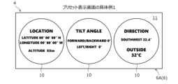
- FIG. 13 is a diagram showing a first specific example of a first display screen.
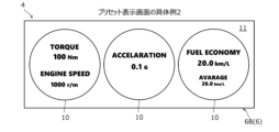
- FIG. 13 is a diagram showing a second specific example of the first display screen.
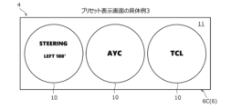
- FIG. 13 is a diagram showing a third specific example of the first display screen.
- FIG. 13 is a diagram showing a fourth specific example of the first display screen.
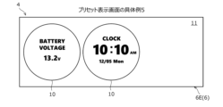
- FIG. 13 is a diagram showing a fifth specific example of the first display screen.
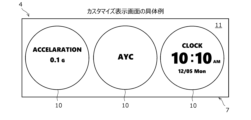
- FIG. 13 is a diagram showing a specific example of a second display screen.
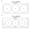
- 10A and 10B are diagrams showing an example of a screen configuration in a meter display mode, in which (a) shows a fixed display and (b) shows a selection display.
- FIG. 13 is a diagram showing a screen configuration in a meter display mode, in which (a) shows a fixed display and (b) shows a selection display.
- FIG. 10A and 10B are diagrams showing an example of a screen configuration in a meter display mode, in which (a) shows a fixed display and (b
- FIG. 1 is a block diagram showing the configuration of a display device 1 according to an embodiment.
- the display device 1 is mounted on a vehicle (not shown) and displays various content information related to the vehicle.
- the content information includes, for example, physical information about the vehicle, information about the output of the vehicle, information about the operation of the vehicle, information about the drive score of the vehicle, outside temperature, and time.
- physical information of a vehicle examples include vehicle position information (latitude, longitude, and altitude), the inclination angle of the vehicle body, and the direction of travel of the vehicle.
- Physical information is generated, for example, in various ECUs (not shown), such as the vehicle integrated ECU (Electronic Control Unit) and the powertrain ECU, based on information acquired through wireless communication with GPS satellites and signals transmitted from various sensors (not shown), such as inclination sensors.
- ECUs such as the vehicle integrated ECU (Electronic Control Unit) and the powertrain ECU, based on information acquired through wireless communication with GPS satellites and signals transmitted from various sensors (not shown), such as inclination sensors.
- output information information related to the output of the vehicle
- output information include the output torque of the drive source (engine or driving motor) not shown, the rotational speed of the drive source, the horsepower (power rate) of the drive source, the longitudinal acceleration of the vehicle, the fuel consumption of the engine, the power consumption of the driving motor, fuel economy and electricity consumption.
- the output information is generated, for example, in various ECUs based on signals transmitted from various sensors such as a rotational speed sensor and a longitudinal acceleration sensor.
- operation information includes steering angle, drive mode, and control mode (e.g., active yaw control (AYC), traction control (TCL)).
- operation information is generated, for example, in various ECUs, based on signals transmitted from various sensors such as a steering angle sensor, and mode information set by user operation.
- score information A specific example of information relating to a vehicle's drive score (hereinafter referred to as "score information”) is the score that evaluates the accelerator operation, steering operation, and brake operation of the driver who drives the vehicle in a specified drive cycle (e.g., one drive cycle).
- the score information is generated, for example, in various ECUs by using a specified algorithm to convert the accelerator operation, steering operation, and brake operation during a specified drive cycle into a numerical value.
- the display device 1 of this embodiment can display other information that indicates the operating status of in-vehicle devices, etc.
- other information include audio information, car navigation information, call information, various websites, etc. This information is generated or acquired by, for example, various ECUs, various in-vehicle devices, various sensors, etc., and transmitted to the display device 1.
- the display device 1 includes an electronic control device 2 and an output device 3.
- the electronic control device 2 is a computer for controlling the content displayed on the output device 3, and includes a processor (arithmetic processing unit) and a memory (storage device).
- the processing content (program) of the electronic control device 2 is stored in the memory, and is executed by loading the content into the processor as appropriate.
- the electronic control device 2 may be formed integrally with the output device 3 (built into the output device 3), or may be provided separately from the output device 3.
- the output device 3 is a device that displays information about the vehicle described above, and is, for example, a liquid crystal display, an organic EL (Electro-Luminescence) display, a projector, etc. All information displayed on the output device 3 is controlled by the electronic control unit 2.
- the shape of the information display area on the output device 3 is not particularly limited, but is, for example, rectangular.
- the output device 3 is placed in a position that is easy for the driver to see, such as in the front center of the vehicle interior (forward of the middle between the driver's seat and the passenger seat) or in front of the driver (forward of the steering wheel).
- Associated devices of the output device 3 a touch panel device that detects touch operations on a screen, an input device provided with a keyboard, physical buttons, or a touchpad, a gaze detection device that detects gaze, a gesture reading device that detects gesture operations, etc. may be provided.
- the display device 1 has at least a meter display mode 4 in which the above-mentioned content information is displayed on a meter display unit 10 (see FIG. 2, for example) as a display mode (display form) of information to be displayed on the output device 3.
- the display device 1 may have another display mode 5 in which the above-mentioned other information is displayed.
- the meter display unit 10 is a circular image (meter image) that imitates an existing analog meter, and is the part that displays content information. Inside the circle of the meter display unit 10, letters, numbers, scales, pictograms, images, videos (video), etc. are displayed.
- Figures 2 to 7 show an example of a meter display unit 10 that only has letters and numbers, it may also be combined with scales, images, etc.
- the meter display unit 10 is displayed within the display area of the output device 3 (display, projector, etc.), but the background 11 other than the meter display unit 10 is not particularly limited and may be a single color (black or white), or may display a pattern or digital time, for example.
- the display device 1 includes a plurality of meter display units 10 prepared in advance. At least one of the above-mentioned content information is displayed on one meter display unit 10.
- the following meter display units 10 are prepared: one that indicates the vehicle's position information (latitude, longitude, altitude), one that indicates the vehicle's inclination angle, one that indicates the vehicle's heading direction, one that indicates output torque, one that indicates rotation speed, one that indicates horsepower (power), one that indicates longitudinal acceleration, one that indicates fuel consumption or power consumption, one that indicates fuel economy or electricity consumption, one that indicates steering angle, one that indicates drive mode, one that indicates control mode, one that indicates drive score, one that indicates outside temperature, one that indicates time, and the like.
- two or more pieces of content information may be displayed on one meter display unit 10.
- the meter display mode 4 has a preset display screen 6 (first display screen) that is set in advance, and a customized display screen 7 (second display screen) that is set by a user of the vehicle (a user of the display device 1).
- the preset display screen 6 is a screen that displays two or more meter display units 10 that have a predetermined relationship with each other among the multiple meter display units 10 side by side on the same screen.
- predetermined relationship means that they have the same attributes (theme), such as the above-mentioned physical information, output information, operation information, and score information.
- meter display units 10 that have a predetermined relationship.
- specific situations include, for example, when driving on a mountain road, when driving in a city, when driving on a highway, when ending driving, etc.
- the preset display screen 6A shown in Fig. 2 has a relationship with the physical vehicle state.
- a meter display section 10 showing the vehicle's three-dimensional position information (latitude, longitude, altitude) and GPS positioning number
- a meter display section 10 center in the figure
- the vehicle's tilt angle front-rear tilt angle, left-right tilt angle
- a meter display section 10 showing the heading direction and outside air temperature
- the above physical information is information that has a relationship with the physical vehicle state.
- the preset display screen 6A in Fig. 2 may include a meter display section 10 showing the above physical information.
- the preset display screen 6B shown in FIG. 3 is related to the output state of the vehicle.
- a meter display section 10 (left in the figure) showing the output torque and rotation speed of the drive source (engine)
- a meter display section 10 center in the figure showing the longitudinal acceleration of the vehicle
- a meter display section 10 (right in the figure) showing the instantaneous fuel consumption and average fuel consumption are displayed side by side on the same screen.
- the above output information is information related to the output state of the vehicle.
- the preset display screen 6B in FIG. 3 may include a meter display section 10 showing the above output information.
- each meter display section 10 in FIG. 3 may have a scale on its circumference, and each piece of information may be displayed together with the extension of the gauge relative to the scale.
- the preset display screen 6C shown in FIG. 4 is related to the driver's operation state (or the vehicle driving state based on the driver's operation).
- a meter display section 10 (left in the figure) showing the steering angle
- a meter display section 10 (center in the figure) showing AYC (right/left turn direction and left/right tire yaw control display)
- a meter display section 10 (right in the figure) showing TCL (right/left turn direction and traction control display) are displayed side by side on the same screen.
- the above operation information is information related to the driver's operation state (or the vehicle driving state based on the driver's operation).
- the preset display screen 6C in FIG. 4 may include a meter display section 10 showing the above operation information.
- it is preferable that information is displayed by images and videos (videos) not shown in addition to text information.
- the preset display screen 6D shown in FIG. 5 has a correlation called a drive score.
- a meter display section 10 showing the score of the accelerator operation
- a meter display section 10 center in the figure
- a meter display section 10 showing the score of the brake operation
- the above score information is information that has a correlation called a drive score.
- the preset display screen 6D in FIG. 5 may include a meter display section 10 showing the above score information.
- the preset display screen 6E shown in FIG. 6 has an association called "others" that does not have the above associations.
- a meter display section 10 (left in the figure) that shows the voltage of the vehicle battery and a meter display section 10 (center in the figure) that shows the date, day of the week, and time are displayed side by side on the same screen, and a space is left on the right side in the figure in which one meter display section 10 can be placed. That is, although only two meter display sections 10 are displayed on the preset display screen 6E in FIG.
- this preset display screen 6E also has three meter display sections 10, just like the preset display screens 6A to 6D in FIG. 2 to FIG. 5.
- the meter display section 10 that shows the time may be a digital display as shown in FIG. 6, an analog display, an analog clock that shows only the time, or one that shows the date and time.
- five types of preset display screens 6 having different associations are preset in the display device 1 of this embodiment.
- the number of preset display screens 6 is not limited to five, and may be one to four, or six or more.
- the preset display screen 6 (6A to 6D) of this embodiment three meter display sections 10 are displayed in a horizontal line at equal intervals with gaps between them so as not to overlap each other.
- the customized display screen 7 is a screen that displays a meter display section 10 that the user has arbitrarily selected from among a plurality of meter display sections 10. In other words, the customized display screen 7 allows the user to freely select the meter display sections 10 that they wish to display and arrange them in the desired positions.
- Figure 7 is an example of a customized display screen 7.
- a meter display section 10 (left in the figure) that shows the vehicle's longitudinal acceleration
- a meter display section 10 center in the figure) that shows AYC (right/left turn direction and left/right tire yaw control display)
- a meter display section 10 (right in the figure) that shows the date, day of the week, and time are displayed side by side on the same screen.
- the number of meter display sections 10 on the customized display screen 7 may be one or more, and is preferably set to the same number as the number of preset display screens 6 (three in this embodiment).
- the display device 1 can be switched between the preset display screen 6 and the customized display screen 7 by a screen switching operation by the user.
- the preset display screens 6A to 6E can also be switched by the screen switching operation by the user.
- the screen switching operation is a predetermined operation that is set according to the output device 3 (or according to an accessory device of the output device 3). For example, if a touch panel device is attached, a touch operation or a swipe operation on an image or screen is set as the screen switching operation. Also, for example, if an input device is attached, a click operation or a press operation on a keyboard, physical button, or touchpad can be set as the screen switching operation. Only one screen switching operation may be set, or multiple screen switching operations may be set.
- the display device 1 of this embodiment is configured to switch between a fixed display that does not accept a screen switching operation by the user and a selection display that can accept the screen switching operation when a predetermined condition is met.
- the fixed display is a display for viewing only
- the selection display is a display that allows the user to operate (editing operation or setting operation). Editing and setting of the customized display screen 7 can be performed in this selection display state.
- full screen size means that the meter display mode 4 is displayed over the entire display area of the output device 3.
- the preset display screens 6A to 6E of Figs. 2 to 6 and the customized display screen 7 of Fig. 7 described above are fixed displays, similar to the screen configuration shown in Fig. 8(a).
- FIG. 8(b) shows the screen configuration in the case of the selection display.
- a reception area 12 that receives the user's screen switching operation and a launcher display area 13 in which a launcher for starting an application is displayed are provided.
- the reception area 12 is provided horizontally at the bottom of the meter display unit 10
- the launcher display area 13 is provided vertically at the left and right of the meter display unit 10, but the arrangement of each area 12, 13 is not limited to this.
- Examples of applications that are started by the launcher include a calling application, a video recording application, a navigation application, and a setting application.
- FIG. 8(b) shows the screen configuration in the case of the selection display.
- a title display area 14 that displays the title of the screen being displayed (e.g., the preset display screen 6) is further provided in the upper center of the display area.
- icons indicating the time, radio wave status, battery level, and mail reception status may be displayed in the four corners (e.g., upper right and upper left) of the background 11.
- FIG. 9 shows a state in which the preset display screen 6A shown in FIG. 2 has been switched to a selection display.
- the reception area 12 displays, for example, the titles of the multiple preset display screens 6 and the title of the customized display screen 7 ("Customize" in FIG. 9), and can receive (detect) a user's touch operation or swipe operation.
- the reception area 12 may have a function for receiving a user operation (selection, arrangement, setting, etc.) for setting the customized display screen 7, in addition to receiving a screen switching operation.
- the reception area 12 may receive a user operation to set the customized display screen 7.
- the reception area 12 and launcher display area 13 that are displayed in the selective display are both hidden, and the meter display section 10 is displayed in a larger size than the size of the meter display section 10 in the selective display.
- the title display area 14 that is displayed in the selective display is also hidden in the fixed display.
- the positional relationship of the three meter display sections 10 remains almost unchanged from the fixed display, their size becomes smaller overall, and the display areas 12 to 14 other than the meter display section 10 are displayed to the left, right, above and below the meter display section 10.
- the specified condition for switching from a fixed display to a selection display is, for example, the user touching a specified area on the screen or pressing a physical button or switch.
- the specified condition for switching from a selection display to a fixed display is, for example, the user touching a specified area on the screen (e.g., the meter display unit 10) or no user operation is performed for a specified period of time during the selection display (timeout).
- the specified conditions for switching between a fixed display and a selection display are not limited to these.
- the screen size in meter display mode 4 can be changed (reduced) from the full screen size in two stages by the user's mode switching operation.
- the meter display unit 10 is configured to be able to change the screen size to one of the full screen size (see FIG. 9), a first reduced size that is approximately two-thirds of the full screen size (see FIG. 10), and a second reduced size that is approximately one-third of the full screen size (see FIG. 11).
- mode switching operations include the user touching a specified area on the screen (e.g., the title display area 14) or pressing a physical button or switch.
- the number of meter display sections 10 on the preset display screen 6 is three, and three meter display sections 10 are displayed at full screen size.
- the number of displayed meter display sections 10 is reduced to two, and at the second reduced size, the number of displayed meter display sections 10 is reduced to one. Note that the sizes of the meter display sections 10 displayed at the first reduced size and the second reduced size are approximately the same, but are slightly smaller than the size of the meter display sections 10 at full screen size.
- the screen size of meter display mode 4 when the screen size of meter display mode 4 is the first reduced size, two of the three meter display sections 10 are displayed side by side, and one is hidden. Also, as shown in FIG. 11, when the screen size of meter display mode 4 is the second reduced size, one of the three meter display sections 10 is displayed, and two are hidden.
- the screen size of meter display mode 4 is the first reduced size or the second reduced size, the meter display section 10 to be displayed is switched by the user's meter switching operation. Examples of meter switching operations include an operation of swiping the meter display section 10 left and right, and an operation of tapping the arrow icon 15 displayed below the meter display section 10.
- the display device 1 has another display mode 5 in addition to the meter display mode 4.
- the other display modes 5 include an audio mode, a car navigation mode, a call mode, a web mode, and an avionics mode (a screen display mode such as that installed on an aircraft).
- the display device 1 displays the other display mode 5 on the same screen as the meter display mode 4 in at least one of the first reduced size and the second reduced size.
- the display device 1 sets the screen size of the other display mode 5 to the second reduced size and displays the two modes 4 and 5 side by side.
- the screen size of the other display mode 5 is the first reduced size and displays the two modes 4 and 5 side by side.
- the screen size of the two other display modes 5 is both the second reduced size and displays the three second reduced size modes 4 and 5 side by side.
- FIG. 10 is an example in which a first reduced-size meter display mode 4 and another second reduced-size display mode 5 (here, call mode 5A) are displayed side by side.
- FIG. 11 is an example in which a second reduced-size meter display mode 4 and another first reduced-size display mode 5 (here, audio mode 5B) are displayed side by side. Note that while FIG. 10 shows an example in which the meter display mode 4 is displayed on the right and FIG. 11 shows an example in which the meter display mode 4 is displayed on the left, the first reduced-size meter display mode 4 may also be displayed on the left, and the second reduced-size meter display mode 4 may also be displayed on the right.
- a home screen (not shown) is provided that displays all modes in a second reduced size, and on that home screen, operations such as changing the order of the modes and switching between display and non-display are possible.
- the order set here is maintained, and when any mode is displayed in the first reduced size, the adjacent modes on the left and right are displayed in the second reduced size.
- the above-described display device 1 has a preset display screen 6 (first display screen) that is set in advance and displays two or more meter display units 10 that have a predetermined correlation with each other among the multiple meter display units 10 side by side on the same screen, and a customized display screen 7 (second display screen) that displays a meter display unit 10 arbitrarily selected by the user from the multiple meter display units 10, and the preset display screen 6 and the customized display screen 7 are switched by a screen switching operation by the user.
- first display screen first display screen
- second display screen that displays a meter display unit 10 arbitrarily selected by the user from the multiple meter display units 10
- the display device 1 is provided with a preset preset display screen 6 and a customized display screen 7 that can be arbitrarily set by the user, and these display screens 6 and 7 can be switched by a screen switching operation by the user, thereby improving convenience for any user.
- the preset display screen 6 displays meter display sections 10 with a predetermined correlation side by side, it is possible to provide the user with content information that is particularly useful in specific situations. For example, when driving on a mountain road, by displaying the preset display screen 6A shown in FIG. 2, the user can understand the location and environment in which the vehicle is traveling and experience active driving scenes from the vehicle's three-dimensional position information (latitude, longitude, altitude), inclination angle information, heading direction, and outside temperature information, thereby providing the user with the enjoyment of driving.
- the number of meter display sections 10 on the preset display screen 6 is the same as the number of meter display sections 10 on the customized display screen 7 (three in each case). This allows the number of meter display sections 10 to remain the same even when switching between the preset display screen 6 and the customized display screen 7, providing a natural impression to the user when switching between the displays.
- the number of meter display sections 10 on the preset display screen 6 is three, and the screen size of the meter display mode 4 is configured to be changeable to one of the full screen size, the first reduced size, and the second reduced size by the user's mode switching operation.
- the first reduced size the number of meter display sections 10 displayed is reduced to two
- the second reduced size the number of meter display sections 10 displayed is reduced to one.
- the screen size of the meter display mode 4 is changed in the reduced direction, the number of meter display sections 10 displayed is reduced, so that the size of the meter display section 10 itself can be maintained and visibility can be ensured.
- the screen size of the meter display mode 4 becomes the first reduced size or the second reduced size, other information can be displayed in the remaining area of the screen, so that other information can be provided together, improving convenience.
- the displayed meter display unit 10 is switched by the user's meter switching operation, so that the user can switch and view the three meter display units 10 even when the screen size is small.
- the display device 1 has a display mode 5 other than the meter display mode 4, and the screen size of the meter display mode 4 is the first reduced size or the second reduced size, if the display device 1 is configured to display the other display mode 5 on the same screen as the meter display mode 4 in at least one of the first reduced size and the second reduced size, it is possible to provide the user with more information and to further improve convenience.
- the selected display has a reception area 12 that accepts screen switching operations and a launcher display area 13 in which a launcher for launching applications is displayed, and in the fixed display, the launcher display area 13 is not displayed and the meter display unit 10 is displayed in an enlarged manner compared to the selected display. Therefore, in the selected display, an app can be easily launched using the launchers on the left and right, improving convenience. Also, in the fixed display, the launcher display area 13 is not displayed and the meter display unit 10 is displayed in an enlarged manner, improving visibility for the user.
- the above-described display device 1 is an example, and is not limited to the above. 2 to 6 are merely examples, and the preset display screens 6 may have the same combinations (e.g., the combination of position, tilt angle, direction, and outside air temperature in FIG. 2) of meter display units 10 arranged in different positions, or the meter display units 10 that display the above-mentioned output information, operation information, etc.
- the content information displayed on one meter display unit 10 may be one type (e.g., only longitudinal acceleration, only steering angle, etc.), or may not include two or more types of content information (e.g., direction, outside air temperature, and weather, output torque, and rotation speed, etc.).
- the method of setting the customized display screen 7 is not limited to the above-mentioned method.
- it may be configured to accept user operations not only in the reception area 12 but also in any area of the selection display screen, allowing the selection and repositioning of the meter display section 10.
- the various user operations described above are also examples, and can be set appropriately depending on the output device 3 and its auxiliary devices.
- the display device 1 does not need to have other display modes 5.
- the empty space may be a background screen with a solid color or a pattern, or some image or video may be displayed.
- FIG. 10 and FIG. 11 explain the case where the selection display of the full screen size is changed to the first reduced size or the second reduced size, the screen size may be reduced from a fixed display of the full screen size. Also, in the first reduced size or the second reduced size, the reception area 12 and the launcher display area 13 may be omitted.
- the preset display screen 6 described above is a triple multimeter with three meter display sections 10 lined up, but the number of meter display sections 10 may be two or more and need not be arranged in a horizontal line.
- four meter display sections 10 may be arranged two by two vertically and five meter display sections 10 may be arranged like an Olympic rings mark.
- the number of meter display sections 10 on the preset display screen 6 and the number of meter display sections 10 on the customized display screen 7 may be different.
- This invention can be used in the manufacturing industry of display devices mounted on vehicles, and also in the manufacturing industry of vehicles equipped with such display devices.
Landscapes
- Engineering & Computer Science (AREA)
- Chemical & Material Sciences (AREA)
- Combustion & Propulsion (AREA)
- Transportation (AREA)
- Mechanical Engineering (AREA)
- Instrument Panels (AREA)
Priority Applications (2)
| Application Number | Priority Date | Filing Date | Title |
|---|---|---|---|
| JP2024575978A JPWO2024166283A1 (cg-RX-API-DMAC7.html) | 2023-02-09 | 2023-02-09 | |
| PCT/JP2023/004339 WO2024166283A1 (ja) | 2023-02-09 | 2023-02-09 | 表示装置 |
Applications Claiming Priority (1)
| Application Number | Priority Date | Filing Date | Title |
|---|---|---|---|
| PCT/JP2023/004339 WO2024166283A1 (ja) | 2023-02-09 | 2023-02-09 | 表示装置 |
Publications (1)
| Publication Number | Publication Date |
|---|---|
| WO2024166283A1 true WO2024166283A1 (ja) | 2024-08-15 |
Family
ID=92262221
Family Applications (1)
| Application Number | Title | Priority Date | Filing Date |
|---|---|---|---|
| PCT/JP2023/004339 Ceased WO2024166283A1 (ja) | 2023-02-09 | 2023-02-09 | 表示装置 |
Country Status (2)
| Country | Link |
|---|---|
| JP (1) | JPWO2024166283A1 (cg-RX-API-DMAC7.html) |
| WO (1) | WO2024166283A1 (cg-RX-API-DMAC7.html) |
Citations (4)
| Publication number | Priority date | Publication date | Assignee | Title |
|---|---|---|---|---|
| JPH10297318A (ja) * | 1997-05-01 | 1998-11-10 | Furukawa Electric Co Ltd:The | インパネ画像選択装置およびその方法 |
| JP2010070078A (ja) * | 2008-09-19 | 2010-04-02 | Nippon Seiki Co Ltd | 車両用表示装置 |
| JP2014130122A (ja) * | 2012-12-29 | 2014-07-10 | Yupiteru Corp | 車両用システム及びプログラム |
| JP2016028240A (ja) * | 2015-09-02 | 2016-02-25 | 株式会社ユピテル | 電子システム及びプログラム |
Family Cites Families (5)
| Publication number | Priority date | Publication date | Assignee | Title |
|---|---|---|---|---|
| JP2017507828A (ja) * | 2014-01-06 | 2017-03-23 | ジョンソン コントロールズ テクノロジー カンパニーJohnson Controls Technology Company | 車両におけるオーディオビジュアルコンテンツの提示及びこれとの相互作用 |
| KR101969805B1 (ko) * | 2017-09-15 | 2019-08-20 | 엘지전자 주식회사 | 차량 제어 장치 및 그것을 포함하는 차량 |
| JP7214542B2 (ja) * | 2019-04-12 | 2023-01-30 | フォルシアクラリオン・エレクトロニクス株式会社 | 表示制御装置、及び表示制御方法 |
| JP7213565B2 (ja) * | 2021-02-16 | 2023-01-27 | 株式会社ユピテル | 装置及びプログラム |
| JP7716081B2 (ja) * | 2021-03-23 | 2025-07-31 | 株式会社ユピテル | システム及びプログラム等 |
-
2023
- 2023-02-09 JP JP2024575978A patent/JPWO2024166283A1/ja active Pending
- 2023-02-09 WO PCT/JP2023/004339 patent/WO2024166283A1/ja not_active Ceased
Patent Citations (4)
| Publication number | Priority date | Publication date | Assignee | Title |
|---|---|---|---|---|
| JPH10297318A (ja) * | 1997-05-01 | 1998-11-10 | Furukawa Electric Co Ltd:The | インパネ画像選択装置およびその方法 |
| JP2010070078A (ja) * | 2008-09-19 | 2010-04-02 | Nippon Seiki Co Ltd | 車両用表示装置 |
| JP2014130122A (ja) * | 2012-12-29 | 2014-07-10 | Yupiteru Corp | 車両用システム及びプログラム |
| JP2016028240A (ja) * | 2015-09-02 | 2016-02-25 | 株式会社ユピテル | 電子システム及びプログラム |
Also Published As
| Publication number | Publication date |
|---|---|
| JPWO2024166283A1 (cg-RX-API-DMAC7.html) | 2024-08-15 |
Similar Documents
| Publication | Publication Date | Title |
|---|---|---|
| CN115535123B (zh) | 摩托车 | |
| CN103909864B (zh) | 车辆显示装置以及包括车辆显示装置的车辆 | |
| EP2726970B1 (en) | Vehicle operation device and vehicle operation method | |
| JP5168322B2 (ja) | 車両用表示装置 | |
| CN113263912B (zh) | 车辆用显示装置 | |
| JP2006010325A (ja) | 表示装置、インストルメントパネル、自動車両およびゲームシステム | |
| CN101101219A (zh) | 车载显示设备和车载显示设备中采用的显示方法 | |
| US20070008189A1 (en) | Image display device and image display method | |
| JP2011113345A (ja) | 車載表示システム | |
| WO2016084360A1 (ja) | 車両用表示制御装置 | |
| US20180074687A1 (en) | Steering wheel hard switch for control of mid software switches | |
| US10088970B2 (en) | Interchangeable display of information panels on a dashboard | |
| KR20160023550A (ko) | 인간-기계 인터페이스 경험을 강화하기 위한 클러스터-라디오 정보 교환 시스템 | |
| CN111559245B (zh) | 显示装置 | |
| US20170168702A1 (en) | Clustered instrument panel in a transportation apparatus | |
| CN201616876U (zh) | 车载多功能显示系统 | |
| JP2020083192A (ja) | 車両用メータユニット | |
| US20120056811A1 (en) | Display device for vehicle | |
| JP2017178300A (ja) | 車両用情報提供装置 | |
| CN113733910A (zh) | 用于机动车辆的智能交互式控制系统 | |
| KR20240162073A (ko) | 차량용 디스플레이 디바이스 | |
| JP7639937B2 (ja) | 表示装置 | |
| JP7758222B2 (ja) | 表示装置 | |
| WO2024166284A1 (ja) | 表示装置 | |
| JP7401017B1 (ja) | 自動車用ディスプレイ |
Legal Events
| Date | Code | Title | Description |
|---|---|---|---|
| 121 | Ep: the epo has been informed by wipo that ep was designated in this application |
Ref document number: 23921114 Country of ref document: EP Kind code of ref document: A1 |
|
| DPE2 | Request for preliminary examination filed before expiration of 19th month from priority date (pct application filed from 20040101) | ||
| WWE | Wipo information: entry into national phase |
Ref document number: 2024575978 Country of ref document: JP |
|
| WWE | Wipo information: entry into national phase |
Ref document number: 2501005255 Country of ref document: TH |
|
| NENP | Non-entry into the national phase |
Ref country code: DE |
|
| 122 | Ep: pct application non-entry in european phase |
Ref document number: 23921114 Country of ref document: EP Kind code of ref document: A1 |