WO2024166201A1 - センサ及び組成物 - Google Patents
センサ及び組成物 Download PDFInfo
- Publication number
- WO2024166201A1 WO2024166201A1 PCT/JP2023/003953 JP2023003953W WO2024166201A1 WO 2024166201 A1 WO2024166201 A1 WO 2024166201A1 JP 2023003953 W JP2023003953 W JP 2023003953W WO 2024166201 A1 WO2024166201 A1 WO 2024166201A1
- Authority
- WO
- WIPO (PCT)
- Prior art keywords
- composition
- current
- sensor
- fine particles
- enzyme
- Prior art date
- Legal status (The legal status is an assumption and is not a legal conclusion. Google has not performed a legal analysis and makes no representation as to the accuracy of the status listed.)
- Ceased
Links
Images








Classifications
-
- G—PHYSICS
- G01—MEASURING; TESTING
- G01N—INVESTIGATING OR ANALYSING MATERIALS BY DETERMINING THEIR CHEMICAL OR PHYSICAL PROPERTIES
- G01N27/00—Investigating or analysing materials by the use of electric, electrochemical, or magnetic means
- G01N27/02—Investigating or analysing materials by the use of electric, electrochemical, or magnetic means by investigating impedance
- G01N27/04—Investigating or analysing materials by the use of electric, electrochemical, or magnetic means by investigating impedance by investigating resistance
- G01N27/12—Investigating or analysing materials by the use of electric, electrochemical, or magnetic means by investigating impedance by investigating resistance of a solid body in dependence upon absorption of a fluid; of a solid body in dependence upon reaction with a fluid, for detecting components in the fluid
- G01N27/125—Composition of the body, e.g. the composition of its sensitive layer
- G01N27/126—Composition of the body, e.g. the composition of its sensitive layer comprising organic polymers
-
- G—PHYSICS
- G01—MEASURING; TESTING
- G01N—INVESTIGATING OR ANALYSING MATERIALS BY DETERMINING THEIR CHEMICAL OR PHYSICAL PROPERTIES
- G01N27/00—Investigating or analysing materials by the use of electric, electrochemical, or magnetic means
- G01N27/02—Investigating or analysing materials by the use of electric, electrochemical, or magnetic means by investigating impedance
- G01N27/04—Investigating or analysing materials by the use of electric, electrochemical, or magnetic means by investigating impedance by investigating resistance
- G01N27/12—Investigating or analysing materials by the use of electric, electrochemical, or magnetic means by investigating impedance by investigating resistance of a solid body in dependence upon absorption of a fluid; of a solid body in dependence upon reaction with a fluid, for detecting components in the fluid
-
- G—PHYSICS
- G01—MEASURING; TESTING
- G01N—INVESTIGATING OR ANALYSING MATERIALS BY DETERMINING THEIR CHEMICAL OR PHYSICAL PROPERTIES
- G01N27/00—Investigating or analysing materials by the use of electric, electrochemical, or magnetic means
- G01N27/26—Investigating or analysing materials by the use of electric, electrochemical, or magnetic means by investigating electrochemical variables; by using electrolysis or electrophoresis
- G01N27/28—Electrolytic cell components
- G01N27/30—Electrodes, e.g. test electrodes; Half-cells
- G01N27/327—Biochemical electrodes, e.g. electrical or mechanical details for in vitro measurements
- G01N27/3271—Amperometric enzyme electrodes for analytes in body fluids, e.g. glucose in blood
- G01N27/3272—Test elements therefor, i.e. disposable laminated substrates with electrodes, reagent and channels
Definitions
- the present invention relates to a sensor and a composition.
- the present invention relates to a chemical resistance type sensor and a composition used therein.
- Electrochemical sensors can be manufactured at low cost, are easy to measure, and allow rapid detection. However, electrochemical sensors require a reference electrode and have a large electrode area, which limits their miniaturization and cost reduction.
- potentiometric sensors require a reference electrode for reliable potential measurement
- amperometric sensors require a reference electrode to apply an accurate potential during measurement.
- the response of potentiometric sensors is highly dependent on the stability of the reference electrode. However, a small solid-state reference electrode with long-term stability has not yet been realized.
- a chemical resistance sensor is a resistance type sensor that detects target molecules by utilizing the change in resistance when the target molecule is adsorbed on the surface of a resistor.
- Chemical resistance sensors are a simple method for measuring chemical substances. Chemical resistance sensors are expected to be used to detect toxic substances and substances related to certain diseases.
- Patent Document 1 discloses a resistive biosensor in which an enzyme is immobilized on a single-walled carbon nanotube. More specifically, it discloses that glucose oxidase is used as the enzyme, and glucose is detected by the hydrogen peroxide produced by the enzyme reaction changing the electrical resistance of the single-walled carbon nanotube.
- Non-Patent Document 1 a conductive polymer, polyaniline, is used as a resistor, and glucose is detected by utilizing the change in resistance associated with a local pH change around the resistor.
- Glucose oxidase is dispersed in the resistor.
- a small amount of platinum nanoparticles is added to oxidize the hydrogen peroxide generated when glucose is oxidized by glucose oxidase.
- the hydrogen peroxide generated as a result of the enzyme reaction reacts with the platinum catalyst, and the conductive polymer is oxidized by the generated hydroxide ions (i.e., OH - ), increasing its resistance.
- the biosensor in Patent Document 1 is manufactured in a complicated manner, and its detection sensitivity is not necessarily high.
- the chemical resistance type sensor in Non-Patent Document 1 has low detection sensitivity because it utilizes the resistance change of polyaniline caused by oxidation.
- the chemical resistance type sensor in Non-Patent Document 1 has a very slow response speed, so it takes about 200 seconds to detect.
- the bandwidth of the glucose concentration that can be detected is narrow, at 0 to 10 mM.
- the object of the present invention is to provide a sensor that has high detection sensitivity and is easy to manufacture.
- a sensor comprising a sensor unit for detecting a target substance in a liquid, a current/voltage control means, and a current/voltage measurement means, wherein the sensor unit comprises first and second electrodes arranged adjacent to each other with a gap therebetween, and a composition arranged between the first and second electrodes and in contact with both, the current/voltage control means and the current/voltage measurement means are electrically connected to the first and second electrodes, the composition comprises a hydrophilic polymer, conductive fine particles and an enzyme, the conductive fine particles and the enzyme are dispersed in the hydrophilic polymer, the content of the conductive fine particles relative to the total mass of the composition is, on a mass basis, a ratio of the composition in a percolation state, and a product produced by the reaction between the target substance and the enzyme electrochemically interacts with the conductive fine particles, causing a change in the electrical resistance value of the composition.
- a composition comprising a hydrophilic polymer, conductive fine particles, and an enzyme, the conductive fine particles and the enzyme being dispersed in the hydrophilic polymer, and the content of the conductive fine particles relative to the total mass of the composition is, on a mass basis, a proportion of the composition in a percolation state.
- the above aspect makes it possible to provide a sensor that has high detection sensitivity and is easy to manufacture, and a composition for use in the sensor.
- FIG. 2 is a schematic diagram of a sensor according to an embodiment.
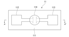
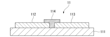
- FIG. 2 is a plan view of a sensor unit according to an embodiment. This is a cross-sectional view of the sensor portion of Figure 2 along the A-A' section.
- 1 is a graph showing the resistance value of a mixture in air using polyvinyl alcohol and platinum nanoparticles versus the mass ratio of platinum nanoparticles in the mixture.
- 5A to 5C are schematic diagrams for explaining a method for manufacturing a sensor according to an embodiment.
- 5A to 5C are schematic diagrams for explaining a method for manufacturing a sensor according to an embodiment.
- 5A to 5C are schematic diagrams for explaining a method for manufacturing a sensor according to an embodiment.
- 5A to 5C are schematic diagrams for explaining a method for manufacturing a sensor according to an embodiment.
- FIG. 13 is a top view of a sensor unit according to another embodiment.
- 1 is a graph showing the resistance value versus glucose concentration in an aqueous glucose solution in the sensor of Example 1.
- 13 is a graph showing the resistance value versus creatinine concentration in an aqueous creatinine solution in the sensor of Example 2.
- a sensor includes a sensor portion for detecting a target substance in a liquid, a current/voltage control means, and a current/voltage measurement means.
- 1 is a schematic diagram of a sensor according to a first embodiment.
- the sensor 1 of this embodiment has a sensor unit 11, a current/voltage control means 12, and a current/voltage measurement means 13.
- the sensor unit 11, the current/voltage control means 12, and the current/voltage measurement means 13 are electrically connected to each other.
- FIG. 2 is a plan view of the sensor unit 11 according to the first embodiment as viewed from the substrate 111 side.
- FIG. 3 is a cross-sectional view of the sensor unit 11 in FIG. 2 along the A-A' cross section.
- the sensor unit 11 of this embodiment has a substrate 111, a first electrode 112, a second electrode 113, and a composition 114.
- the substrate 111 may be an insulating substrate, such as a glass substrate, a silicon substrate, or a printed circuit board.
- the first and second electrodes 112 and 113 are located on the substrate 111.
- the first and second electrodes 112 and 113 are disposed adjacent to each other with a gap therebetween.
- the gap between the first and second electrodes 112 and 113 is preferably 10 to 100 ⁇ m.
- the first and second electrodes 112 and 113 are conductive metal thin films.
- the material of the conductive metal thin film is not particularly limited, but examples include gold, silver, chromium, copper, and alloys thereof, or conductive carbon.
- the conductive metal thin film may be a single layer of the material, or may be a multilayer of two or more layers. It is desirable to protect the surfaces of the electrodes 112 and 113 with an insulating resin or the like to prevent leakage current.
- the composition 114 is disposed on the first and second electrodes 112 and 113 and on the substrate 111 so as to fill the gap between the first and second electrodes 112 and 113.
- the composition 114 is in contact with the first and second electrodes 112 and 113.
- the composition 114 includes a hydrophilic polymer, conductive fine particles, and an enzyme.
- the conductive fine particles and the enzyme are dispersed in the hydrophilic polymer. In other words, the conductive fine particles spread throughout the gap between the first and second electrodes 112 and 113 at least without short-circuiting.
- the enzyme is dispersed not only on the surface of the composition 114 but throughout the composition 114, that is, inside the composition 114 as well. By locating the enzyme inside the composition 114 as well, the resistance value of the composition 114 can be easily changed by the reaction between the enzyme and the target substance, improving the detection sensitivity of the target substance.
- the hydrophilic polymer is an insulating hydrophilic polymer.
- hydrophilic polymers examples include polyvinyl alcohol, polyethylene glycol, polyvinyl acetate, and cellulose fiber, with polyvinyl alcohol being preferred.
- a hydrophilic polymer in composition 114 the target substance in the liquid and the enzyme come into contact with each other even inside composition 114, improving the detection sensitivity of the target substance in water. It is preferable that the hydrophilic polymer does not expand or contract due to the reaction between the enzyme and the target substance, and is capable of stably holding the conductive microparticles.
- the ratio of the hydrophilic polymer to the total mass of the composition 114 is preferably 20% by mass or more and 90% by mass or less.
- the metal microparticles are Pt with a diameter of 2 nm
- the ratio of the hydrophilic polymer to the total mass of the composition 114 is 30% by mass or more and 50% by mass or less, the composition 114 can be easily controlled to the mass ratio of the conductive microparticles in a percolation state.
- the conductive fine particles are preferably at least one of metal fine particles, graphite fine particles, and graphite fine wires.
- the metal fine particles refer to metal particles having a particle diameter of 1 to 80 nm.
- the particle diameter of the metal fine particles is preferably 1 to 50 nm, and more preferably 1 to 20 nm.
- the metal fine particles may be metal fine particles having a catalytic action that promotes the decomposition reaction of the electrode active material (for example, when the target substance is creatinine, hydrogen peroxide water generated by a cascade reaction) accompanying the reaction of the target substance with the enzyme, and are preferably noble metal fine particles.
- noble metal fine particles include platinum nanoparticles, gold nanoparticles, silver nanoparticles, and palladium nanoparticles.
- the graphite fine particles refer to graphite particles having a diameter of 10 to 90 nm.
- the graphite fine wire refers to filamentous graphite having a diameter of 1 to 20 nm and a length of 2 to 50 ⁇ m (i.e., carbon nanofibers and carbon nanotubes).
- the particle size means the median size (also called D50 ).
- the mass ratio of the conductive fine particles contained in the composition is controlled so that the composition is in a percolation state.
- the electrical conductivity changes as the ratio of the conductive fine particles increases.
- a conductive path is formed by the connected fine particles, and the electrical conductivity of the mixture increases rapidly.
- Such a sudden increase in electrical conductivity is called the percolation phenomenon.
- the region in which the electrical conductivity changes rapidly is very sensitive to slight changes in carriers.
- a sensor with excellent sensitivity can be provided by using a region in which the electrical conductivity of the mixture changes rapidly beyond a certain ratio.
- the resistance value R of the composition is too large, noise increases and the composition is not suitable for measurement. Therefore, when the resistance value of the water-soluble polymer when a constant current or voltage is applied is R1 and the resistance value when an excessive amount of conductive fine particles is added to the water-soluble polymer is R2 , the resistance value R is preferably in the range of 2.0 ⁇ R2 ⁇ R ⁇ 0.8 ⁇ R1 , and more preferably is a value of ( R1 + R2 )/2.5 ⁇ R ⁇ ( R1 + R2 )/1.75.
- Fig. 4 is a graph showing the resistance value of a mixture in air versus the mass ratio of platinum nanoparticles in a mixture using polyvinyl alcohol as a water-soluble polymer and platinum nanoparticles as conductive particles.
- the measurement voltage is 0.5 V.
- the horizontal axis is the amount of deionized water containing 4% by mass of platinum nanoparticles added to 3 mL of deionized water containing 4% by mass of polyvinyl alcohol.
- the resistance value R1 is 1000 M ⁇
- the resistance value R2 is 100 M ⁇ .
- the resistance value R of the mixture is preferably a value in the vicinity of 600 M ⁇ , for example, 480 M ⁇ or more and 685 M ⁇ or less.
- the mass ratio of the conductive fine particles when the composition is in a percolation state is preferably such that the resistance value in air of the mixture of the water-soluble polymer and the conductive fine particles is 200 M ⁇ or more and 800 M ⁇ or less, more preferably 300 M ⁇ or more and 750 M ⁇ or less, even more preferably 500 M ⁇ or more and 700 M ⁇ or less, and particularly preferably 550 M ⁇ or more and 650 M ⁇ or less.
- the mass ratio of the conductive fine particles when the composition is in a percolation state is preferably such that the resistance value of the mixture of the water-soluble polymer and the conductive fine particles in water is 0.01 M ⁇ or more and 10 M ⁇ or less, and more preferably 0.05 M ⁇ or more and 3 M ⁇ or less.
- the mass ratio of the conductive microparticles in which composition 114 is in a percolation state is, for example, preferably 30% by mass or more and 75% by mass or less, more preferably 35% by mass or more and 70% by mass or less, and even more preferably 35% by mass or more and 65% by mass or less, as the mass of the conductive microparticles relative to the total mass of composition 114.
- composition 114 By controlling the mass ratio of the conductive fine particles contained in composition 114 so that the composition is in a percolation state, composition 114 exhibits a large change in resistance even when the electrical change due to the reaction between the target substance and the enzyme is small, thereby improving the sensitivity of the sensor.
- the enzyme is not particularly limited as long as it can be dispersed and supported in a hydrophilic polymer and produces an electrode active material in a reaction between the target substance and the enzyme, and an enzyme capable of detecting the target substance is appropriately selected.
- the electrode active material produced by the catalytic reaction of the enzyme is oxidized or reduced by the conductive fine particles, which are the electrochemical catalyst, and exchanges charges with the conductive fine particles.
- Examples of the electrode active material include hydrogen peroxide, oxygen, ammonia, hydrogen, and carbon dioxide.
- Hydrogen peroxide is an electrode active material that contributes to both oxidation and reduction, and can exchange charges with the conductive fine particles through the following reaction. ( Oxidation reaction) H2O2 ⁇ O2 + 2H ++ 2e- ( Reduction reaction) H2O2 + 2H ++ 2e- ⁇ 2H2O
- the conductive fine particles are negatively ionized, and depending on the conditions, the electrons contribute to hopping conduction or tunneling conduction, thereby decreasing the resistance of composition 114.
- the conductive fine particles are stable in a negatively charged state due to electrons, the charge caused by the electrification of the conductive fine particles changes the potential barrier, causing a decrease in the electrical conductivity of composition 114.
- the reduction reaction is dominant, the conductive fine particles are positively ionized, and the carriers contributing to electrical conduction decrease, causing an increase in the resistance of composition 114.
- These oxidation-reduction reactions may occur simultaneously in the conductive fine particles, in which case electrical conduction occurs in composition 114 in which the conductive fine particles are dispersed, depending on the concentration of the electrode active material.
- the enzyme may be one type or two or more types. When two or more types of enzymes are used, it is not necessary for hydrogen peroxide to be produced in all enzyme reactions, as long as at least one enzyme reaction produces an electrode active material.
- the target substance is creatinine
- three types of enzymes can be used: creatininase, creatinase, and sarcosine oxidase.
- Creatininase, creatinase, and sarcosine oxidase (hydrolysis reaction) creatinine + H 2 O ⁇ creatine (hydrolysis reaction) creatine + H 2 O ⁇ sarcosine + urea (oxidation reaction) sarcosine + H 2 O + O 2 ⁇ glycine + HCHO + H 2 O 2
- the mass ratio of the enzyme to the total mass of composition 114 is preferably 0.01% by mass or more and 10% by mass or less, more preferably 0.02% by mass or more and 8% by mass or less, and even more preferably 0.05% by mass or more and 5% by mass or less.
- the current/voltage control means 12 and the current/voltage measurement means 13 may be implemented using well-known electrochemical measurement devices such as a potentiostat/galvanostat measurement station.
- the sensor 1 may further include a first estimation unit.
- the first estimation unit controls the current/voltage control means 12 to apply a voltage to the composition 114, and controls the current value at that time to be measured by the current/voltage measurement means 13, thereby acquiring a current/voltage curve.
- the first estimation unit can estimate the electrical resistance value of the composition 114 from the current/voltage curve.
- the sensor 1 may further include a second estimation unit.
- the second estimation unit controls the current-voltage control means 12 to apply a current to the composition 114, and controls the current-voltage measurement means 13 to measure the voltage value at that time, thereby acquiring a current-voltage curve.
- the second estimation unit can estimate the electrical resistance value of the composition 114 from the current-voltage curve.
- a sensor with the above configuration can detect target substances in liquids with high sensitivity.
- a method for detecting a target substance using a sensor in this embodiment will be described.
- the sensor portion 11 of the sensor 1 is immersed in a sample, which is a liquid containing the target substance.
- a constant current or voltage is applied using the current/voltage control means 12.
- a constant voltage is applied to the sensor 1, and the current value at that time is measured.
- a calibration curve of the current value versus the mass ratio of the target substance per sample volume is prepared in advance, and the mass ratio of the target substance can be obtained from the measured current value.
- the electrical resistance value can be estimated by the above-mentioned first estimation unit or second estimation unit.
- the sensor of this embodiment can detect the target substance.
- the current-voltage control means 12 may scan the voltage of the sensor 1 at a predetermined range, detect the current at that time with the current-voltage measurement means 13, and estimate the electrical resistance value of the composition 114 from the current-voltage curve obtained as a result.
- the current-voltage control means 12 may scan the current passed through the sensor 1, detect the voltage at that time with the current-voltage measurement means 13, and estimate the electrical resistance value of the composition 114 from the current-voltage curve obtained as a result.
- the target substance may be continuously brought into contact with the sensor 1 by flowing or circulating a liquid sample.
- a liquid delivery pump, syringe pump, or the like may be used to achieve this.
- a conductive metal thin film 115 is formed on a substrate 111.
- One method for forming the conductive metal thin film 115 is sputtering.
- the conductive metal thin film 115 is formed as a single layer, but the conductive metal thin film 115 may be a multilayer film having two or more layers. The materials mentioned above can be used as the material for the conductive metal thin film.
- a photoresist layer 116 is formed on the conductive metal thin film 115.
- a positive type resist or a negative type photoresist may be used.
- the positive type resist for example, OFPR800 manufactured by Tokyo Ohka Kogyo Co., Ltd. may be used.
- the negative type resist for example, OMR83 manufactured by Tokyo Ohka Kogyo Co., Ltd. may be used. In this embodiment, an example using a positive type photoresist will be described.
- the photoresist layer 116 is irradiated with ultraviolet light through a photomask 117.
- the photoresist layer 116 is then developed using a developer to form a photoresist pattern 118.
- the conductive metal thin film 115 is etched through the photoresist pattern 118 to form the first and second electrodes 112 and 113.
- a metal etchant can be used as the etching liquid.
- a mixed liquid containing a hydrophilic polymer, conductive microparticles and enzyme is prepared.
- the hydrophilic polymer, conductive microparticles and enzyme are weighed taking into account the final mass ratio in the composition.
- the weighed hydrophilic polymer, conductive microparticles and enzyme are each added to deionized water to prepare a hydrophilic polymer liquid, a conductive microparticle liquid and an enzyme liquid, which are then mixed to prepare a mixed liquid.
- a well-known method may be used so that the conductive microparticles and enzyme are dispersed as uniformly as possible within the hydrophilic polymer.
- the mixed liquid is dropped onto the first and second electrodes 112 and 113 and onto the substrate 111 so as to fill the gaps between the first and second electrodes 112 and 113.
- the method for dropping the mixed liquid is not particularly limited, but inkjet is preferable.
- the mixture is dried to form a composition 114.
- conductive particles are dispersed in a hydrophilic polymer, and an enzyme is supported by the hydrophilic polymer.
- the first and second electrodes 112 and 113 are connected to the current/voltage control means 12 and the current/voltage measurement means 13 by wiring, completing the sensor 1.
- FIG. 6 is a top view of the sensor unit according to this embodiment.
- the sensor unit 11' of this embodiment includes first to third electrodes 112, 113, and 119, a composition 114, and a reference composition 120.
- the second electrode 113 is disposed adjacent to the first electrode 112 via a gap, and is also disposed adjacent to the third electrode 119 via a gap.
- the reference composition 120 is disposed on the second and third electrodes 113 and 119 and on the substrate 111 so as to fill the gap between the second and third electrodes 113 and 119.
- the reference composition 120 is in contact with the second and third electrodes 113 and 119.
- the third electrode 119 is the same conductive thin film as the first and second electrodes 112 and 113.
- the reference composition 120 is a mixture of hydrophilic polymer and conductive particles, the same as composition 114, except that it does not contain the enzyme.
- the first and second electrodes 112 and 113 and the composition 114 are the target substance detection element
- the second and third electrodes 113 and 119 and the reference composition 120 are the reference element.
- Example 1 A 20 nm-thick chromium thin film was formed on a Tempax glass substrate using a sputtering device (Shibaura Mechatronics, CFS-4ES). A 0.1 ⁇ m-thick gold thin film was formed on this chromium thin film using a sputtering device (Shibaura Mechatronics, CFS-4ES). A positive photoresist (Tokyo Ohka, product number: OFPR800-30CP) was applied onto the gold thin film, and a photoresist pattern was formed by irradiating ultraviolet light through a photomask and developing with a developer. Thereafter, the first and second electrodes were fabricated by etching and patterning the metal with gold and chromium etchants. The shortest distance between the first and second electrodes was 50 ⁇ m.
- Mixed solution 1 was prepared by mixing platinum nanoparticles (Tanaka Kikinzoku, particle size: 2 nm) with deionized water. The platinum nanoparticles accounted for 4 mass% of the mass of mixed solution 1.
- Mixed solution 2 was prepared by mixing polyvinyl alcohol (Fujifilm Wako Pure Chemical Industries, Ltd.) with deionized water and adding 0.6 wt% boric acid to crosslink and stabilize the polyvinyl alcohol. The polyvinyl alcohol accounted for 4 mass% of the mass of mixed solution 2.
- Mixed solution 3 was prepared by mixing 0.11 mg (30 mU) of glucose oxidase (Nacalai Tesque, product number: 16831-01) with 1 mL of deionized water.
- the liquid obtained by mixing mixtures 1 to 3 was dropped with a pipette into the gap between the first and second electrodes and onto the ends of the first and second electrodes, and then dried at 45°C for 60 minutes to form a composition with a thickness of 5 to 10 ⁇ m.
- the first and second electrodes and composition on the glass substrate thus formed were used as the sensor part.
- the first and second wiring were connected to the first and second electrodes, respectively.
- a current-voltage control means manufactured by Keithley, part number: 2400
- a current-voltage measurement means manufactured by Keithley, part number: 2400
- the sensor part of the manufactured sensor was immersed in aqueous glucose solutions with glucose concentrations of 0.05 mol/L, 0.1 mol/L, 0.2 mol/L, and 0.5 mol/L, respectively, and a constant current of 640 ⁇ A was passed using the current-voltage control means, and the resistance value of the sensor part was obtained from the voltage value at that time.
- Figure 7 is a graph showing the resistance value of the sensor part versus the glucose concentration in the aqueous glucose solution in the sensor of Example 1. It was found that the resistance value of the sensor part decreased as the concentration of glucose contained in the sample increased.
- Example 2 First and second electrodes were prepared on a glass substrate by the method described in Example 1.
- Mixture 4 was prepared by mixing 0.5 mg of creatinase (Sigma-Aldrich, product number: C3921-500UN), 5.7 mg of creatinase (Sigma-Aldrich, product number: C3172-1KU), and 2.3 mg of sarcosine oxidase (Sigma-Aldrich, product number: S7897-1KU) in 1 mL of deionized water.
- the liquid obtained by mixing mixed solutions 1, 2, and 4 was dropped with a pipette so as to cover the gap between the first and second electrodes and the ends of the first and second electrodes, and the sensor part was produced by drying at 45°C for 60 minutes.
- the manufacturing process for the sensor was the same as that of Example 1 except for the sensor part.
- the sensor part of the manufactured sensor was immersed in creatinine aqueous solutions with creatinine concentrations of 0 mg/dL, 3 mg/dL, 6 mg/dL, 25 mg/dL, 50 mg/dL, 75 mg/dL, 100 mg/dL, 150 mg/dL, 200 mg/dL, 250 mg/dL, and 300 mg/dL, respectively, and a voltage of 0.1 to 1.0 V was applied in increments of 0.1 V by the current/voltage control means, and the resistance value of the sensor part was obtained from the current value at that time.
- Figure 8 is a graph showing the resistance value of the sensor part versus the creatinine concentration in the creatinine aqueous solution in the sensor of Example 2. It was found that the resistance value of the sensor part decreased as the concentration of creatinine in the sample increased.
- Target substances include peptidyl-L-lysyl peptide, xanthine, uric acid, L-amino acids, cholesterol, L-lactate, pyruvic acid, histamine, peptidyl-L-lysyl peptide, etc., and can be measured using the following enzymes: protein-lysine-6-oxidase, xanthine oxidase, uric acid oxidase, L-amino acid oxidase, cholesterol oxidase, lactate oxidase, pyruvic acid oxidase, diamine oxidase, and protein-lysine-6-oxidase, respectively.
- the above aspect makes it possible to provide a sensor that has high detection sensitivity and is easy to manufacture, and a composition for use in the sensor.
Landscapes
- Chemical & Material Sciences (AREA)
- Health & Medical Sciences (AREA)
- Life Sciences & Earth Sciences (AREA)
- General Health & Medical Sciences (AREA)
- Physics & Mathematics (AREA)
- Electrochemistry (AREA)
- Analytical Chemistry (AREA)
- Biochemistry (AREA)
- Chemical Kinetics & Catalysis (AREA)
- General Physics & Mathematics (AREA)
- Immunology (AREA)
- Pathology (AREA)
- Biophysics (AREA)
- Hematology (AREA)
- Molecular Biology (AREA)
- Investigating Or Analyzing Materials By The Use Of Electric Means (AREA)
Abstract
このセンサ(1)は、液体中の対象物質を検出するセンサ部(11)と、電流電圧制御手段(12)と、電流電圧測定手段(13)と、を備えたセンサ(1)であって、センサ部は、空隙を介して互いに隣接して配置される第1及び第2電極(112)、(113)と、第1及び第2電極の間に配置され、両者に接触している組成物(114)と、を含み、電流電圧制御手段及び電流電圧測定手段は、第1及び第2電極と電気的に接続されており、組成物は、親水性ポリマー、導電性微粒子及び酵素を含み、導電性微粒子及び酵素は、親水性ポリマー中に分散しており、組成物の総質量に対する導電性微粒子の含有量が、質量基準で、組成物がパーコレーション状態の割合であり、対象物質と酵素との反応により生成する生成物が導電性微粒子と電気化学的に相互作用し、組成物の電気抵抗値が変化する。
Description
本発明は、センサ、及び、組成物に関する。特に、本発明は、化学抵抗型センサ及びそれに用いられる組成物に関する。
電気化学センサは、低コストで製造が可能であり、計測が簡易であり、迅速な検出が可能である。しかしながら電気化学センサは、参照電極が必要であり電極面積が広いため、小型化や低コスト化の制限がある。電気化学センサのうち、電位差センサは、信頼性の高い電位測定のために参照電極を必要とし、アンペロメトリックセンサでは、測定において正確な電位を印可するために参照電極を必要とする。電位差センサの場合、その応答が参照電極の安定性に強く依存する。しかしながら、長期的な安定性を備えた小型の固体参照電極は、まだ実現されていない。
最近では、化学抵抗型センサ、コンダクタメトリックセンサ、及び電界効果型センサなどが化学物質検出の目的で開発されている。
化学抵抗型センサは、抵抗体の表面に対象分子が吸着した際に、その抵抗が変化することを利用して対象分子を検出する抵抗型のセンサである。化学抵抗型センサは、化学物質の測定手法としては単純なものであるといえる。化学抵抗型センサは、有毒物質の検出及び特定の疾患に関与する物質の検出等への応用が期待されている。
特許文献1は、単層カーボンナノチューブに酵素を固定した抵抗型バイオセンサーを開示している。より具体的には、酵素としてグルコースオキシダーゼを利用し、酵素反応により生じる過酸化水素が単層カーボンナノチューブの電気抵抗を変化させることでグルコースを検出することを開示している。
非特許文献1は、導電性ポリマーであるポリアニリンを抵抗体とし、この抵抗体の周囲の局所的なpH変化に伴う抵抗変化を利用してグルコースを検出している。抵抗体には、グルコースオキシダーゼが分散している。グルコースをグルコースオキシダーゼで酸化する際に発生する過酸化水素を酸化する目的で、微量の白金ナノ微粒子が添加されている。グルコースが存在すると、酵素反応の結果として発生した過酸化水素が白金触媒と反応し、発生した水酸化物イオン(つまりOH-)により導電性ポリマーが酸化されその抵抗が大きくなる。
Edward Song, Tallis H. da Costa, Jin-Woo Choi, A chemiresistive glucose sensor fabricated by inkjet printing, Microsyst. Technol., 23 (2017) 3505-3511
特許文献1のバイオセンサーは、製造方法が複雑であり、検出感度が必ずしも高くない。また、非特許文献1の化学抵抗型センサは、酸化によるポリアニリンの抵抗変化を利用しているため、検出感度が低い。また、非特許文献1の化学抵抗型センサは、応答速度が非常に遅いため、検出に200秒間程度かかる。また、その検出できるグルコース濃度の帯域幅は、0~10mMと狭い。
本発明の目的は、検出感度が高く、かつ容易に製造できるセンサを提供することにある。
本発明は、以下の態様を包含する。
液体中の対象物質を検出するセンサ部と、電流電圧制御手段と、電流電圧測定手段と、を備えたセンサであって、前記センサ部は、空隙を介して互いに隣接して配置される第1及び第2電極と、前記第1及び第2電極の間に配置され、両者に接触している組成物と、を含み、前記電流電圧制御手段及び前記電流電圧測定手段は、前記第1及び第2電極と電気的に接続されており、前記組成物は、親水性ポリマー、導電性微粒子及び酵素を含み、前記導電性微粒子及び前記酵素は、前記親水性ポリマー中に分散しており、前記組成物の総質量に対する前記導電性微粒子の含有量が、質量基準で、前記組成物がパーコレーション状態の割合であり、前記対象物質と前記酵素との反応により生成する生成物が前記導電性微粒子と電気化学的に相互作用し、前記組成物の電気抵抗値が変化する、センサ。
液体中の対象物質を検出するセンサ部と、電流電圧制御手段と、電流電圧測定手段と、を備えたセンサであって、前記センサ部は、空隙を介して互いに隣接して配置される第1及び第2電極と、前記第1及び第2電極の間に配置され、両者に接触している組成物と、を含み、前記電流電圧制御手段及び前記電流電圧測定手段は、前記第1及び第2電極と電気的に接続されており、前記組成物は、親水性ポリマー、導電性微粒子及び酵素を含み、前記導電性微粒子及び前記酵素は、前記親水性ポリマー中に分散しており、前記組成物の総質量に対する前記導電性微粒子の含有量が、質量基準で、前記組成物がパーコレーション状態の割合であり、前記対象物質と前記酵素との反応により生成する生成物が前記導電性微粒子と電気化学的に相互作用し、前記組成物の電気抵抗値が変化する、センサ。
親水性ポリマー、導電性微粒子及び酵素を含む組成物であって、前記導電性微粒子及び前記酵素は、前記親水性ポリマー中に分散しており、前記組成物の総質量に対する前記導電性微粒子の含有量が、質量基準で、前記組成物がパーコレーション状態の割合である組成物。
上記態様によれば、検出感度が高く、かつ容易に製造できるセンサ及び当該センサに用いられる組成物を提供することができる。
〈第1の実施形態〉
(センサ)
以下、図面を参照しながら実施形態について詳しく説明する。
ただし、以下に示す実施形態はあくまでも例示に過ぎず、実施形態で明示しない種々の変形例や技術の適用を排除する意図はない。また、図面に示される一例のサイズや比は、理解を容易にするため、一部を拡大して記載されているものもあり、又、形状も、一例である。必ずしもそれに限られるものではない。すなわち、本実施形態を、その趣旨を逸脱しない範囲で種々変形して実施することができる。
(センサ)
以下、図面を参照しながら実施形態について詳しく説明する。
ただし、以下に示す実施形態はあくまでも例示に過ぎず、実施形態で明示しない種々の変形例や技術の適用を排除する意図はない。また、図面に示される一例のサイズや比は、理解を容易にするため、一部を拡大して記載されているものもあり、又、形状も、一例である。必ずしもそれに限られるものではない。すなわち、本実施形態を、その趣旨を逸脱しない範囲で種々変形して実施することができる。
本発明の一態様におけるセンサは、液体中の対象物質を検出するセンサ部と、電流電圧制御手段と、電流電圧測定手段と、を備える。
図1は、第1の実施形態に係るセンサの模式図である。本実施形態のセンサ1は、センサ部11と、電流電圧制御手段12と、電流電圧測定手段13とを有する。センサ部11、電流電圧制御手段12及び電流電圧測定手段13は、電気的に接続されている。
図1は、第1の実施形態に係るセンサの模式図である。本実施形態のセンサ1は、センサ部11と、電流電圧制御手段12と、電流電圧測定手段13とを有する。センサ部11、電流電圧制御手段12及び電流電圧測定手段13は、電気的に接続されている。
図2は、第1の実施形態に係るセンサ部11を基板111側から見たときの平面図である。図3は、図2のセンサ部11のA-A’断面における断面図である。本実施形態のセンサ部11は、基板111、第1電極112、第2電極113及び組成物114を有する。
基板111は、絶縁基板を用いることができ、例えばガラス基板、シリコン基板又はプリント基板等を用いることができる。
第1及び第2電極112及び113は、基板111上に位置する。第1及び第2電極112及び113は、空隙を介して互いに隣接して配置される。第1及び第2電極112及び113の間隙は、10~100μmであることが好ましい。第1及び第2電極112及び113は、導電性金属薄膜である。導電性金属薄膜の材料は、特に限定されないが、例えば金、銀、クロム、銅等及びこれらの合金、又は、導電性炭素が挙げられる。導電性金属薄膜は、前記材料の単層でもよく、2層以上の多層でもよい。電極112及び113の表面は、リーク電流を防ぐために絶縁性の樹脂等で保護しておくのが望ましい。
組成物114は、第1及び第2電極112及び113間の空隙を埋めるように、第1及び第2電極112及び113上、並びに基板111上に配置される。組成物114は、第1及び第2電極112及び113に接触している。組成物114は、親水性ポリマー、導電性微粒子及び酵素を含む。導電性微粒子及び酵素は、親水性ポリマーに分散している。言い換えれば、第1及び第2電極112及び113間の空隙を、導電性微粒子は、少なくとも短絡することなく全体に広がっている。酵素は、組成物114表面のみでなく、組成物114全体に、つまり組成物114の内部にも分散していることが好ましい。酵素が組成物114の内部にも位置することで、酵素と対象物質との反応により組成物114の抵抗値を変動させやすく、対象物質の検出感度が向上する。
親水性ポリマーは、絶縁性の親水性ポリマーである。親水性ポリマーとしては、ポリビニルアルコール、ポリエチレングリコール、ポリ酢酸ビニル、セルロースファイバー等を用いることができ、ポリビニルアルコールであることが好ましい。組成物114が親水性ポリマーを含むことで、液体中の対象物質と酵素とが組成物114の内部においても接触するため、水中の対象物質の検出感度が向上する。なお、親水性ポリマーは、酵素と対象物質との反応により伸長または収縮などが起きず、安定して導電性微粒子を保持できるものであることが好ましい。
組成物114の総質量に対する親水性ポリマーの割合は、20質量%以上90質量%以下であることが好ましい。例えば、金属微粒子が2nmの直径のPtの場合には、組成物114の総質量に対する親水性ポリマーの割合が30質量%以上50質量%以下であると、組成物114がパーコレーション状態である導電性微粒子の質量割合に制御しやすい。
導電性微粒子としては、金属微粒子、グラファイト微粒子及びグラファイト細線の少なくとも1つであることが好ましい。金属微粒子とは、粒子径が1~80nmの金属粒子を意味する。金属微粒子の粒子径は、1~50nmであることが好ましく、1~20nmであることがより好ましい。金属微粒子としては、対象物質と酵素の反応に伴う、電極活物質(例えば、対象物質がクレアチニンであった場合、カスケード反応により生じる過酸化水素水等。)の分解反応を促進する触媒作用を有する金属の微粒子であればよく、貴金属微粒子であることが好ましい。貴金属微粒子の具体例として、白金ナノ微粒子、金ナノ微粒子、銀ナノ微粒子及びパラジウムナノ微粒子等が挙げられる。なかでも、白金ナノ微粒子であることが好ましい。グラファイト微粒子とは、10~90nmのグラファイト粒子を意味する。グラファイト細線とは、直径が1~20nm、長さが2~50μmの糸状のグラファイト(つまり、カーボンナノファイバーやカーボンナノチューブ)を意味する。なお、本明細書において粒子径とは、メディアン径(D50ともいう。)を意味する。
組成物に含まれる導電性微粒子の質量割合は、組成物がパーコレーション状態となるよう制御されている。絶縁性ポリマー等の絶縁体に導電性微粒子を添加した混合物は、導電性微粒子の割合が増加すると電気伝導度が変化する。導電性微粒子がある一定の割合を超えると、連結した微粒子による導電パスが形成されて混合物の電気伝導度が急激に上昇する。このような電気伝導度の急激な上昇は、パーコレーション現象と呼ばれる。電気伝導度が急激に変化する領域は、わずかなキャリアの変化に対して非常に敏感である。本実施形態では、ある一定の割合を超え混合物の電気伝導度が急激に変化する領域を用いることで、感度の優れたセンサを提供できる。本明細書において「組成物がパーコレーション状態である」とは、導電性微粒子の密度の変化に伴って、組成物が上述の電気伝導度の急激な変化を生じる範囲の割合で導電性微粒子を含み、分散していることを示す。
本実施形態における組成物の抵抗値Rは、その値が大きすぎるとノイズが多くなり測定に適さない。そのため、一定の電流又は電圧を印加したときの水溶性ポリマーの抵抗値をR1、水溶性ポリマーに過剰に導電性微粒子を添加した状態における抵抗値をR2としたとき、抵抗値Rは、2.0×R2≦R≦0.8×R1の範囲となることが好ましく、(R1+R2)/2.5≦R≦(R1+R2)/1.75の値であることがより好ましい。
例えば、図4は、水溶性ポリマーとしてポリビニルアルコール、導電性微粒子として白金微粒子を用いた混合物における白金ナノ微粒子の質量割合に対する大気中での混合物の抵抗値を示すグラフである。測定電圧は、0.5Vである。横軸は、4質量%のポリビニルアルコール添加脱イオン水3mLに対する4質量%の白金ナノ微粒子添加脱イオン水の添加量である。この例において、抵抗値R1は、1000MΩであり、抵抗値R2は、100MΩである。混合物の抵抗値Rは、600MΩ近傍の値であることが好ましく、例えば480MΩ以上685MΩ以下であることが好ましい。
組成物がパーコレーション状態である導電性微粒子の質量割合は、水溶性ポリマーと導電性微粒子との混合物の大気中での抵抗値が200MΩ以上800MΩ以下となる質量割合が好ましく、300MΩ以上750MΩ以下となる質量割合がより好ましく、500MΩ以上700MΩ以下となる質量割合がさらに好ましく、550MΩ以上650MΩ以下となる質量割合が特に好ましい。
また、組成物がパーコレーション状態である導電性微粒子の質量割合は、水溶性ポリマーと導電性微粒子との混合物の水中での抵抗値が0.01MΩ以上10MΩ以下となる質量割合が好ましく、0.05MΩ以上3MΩ以下となる質量割合がより好ましい。
例えば、導電性微粒子として白金ナノ微粒子を用いる場合、組成物114がパーコレーション状態である導電性微粒子の質量割合は、一例として組成物114の総質量に対する導電性微粒子の質量としては、30質量%以上75質量%以下が好ましく、35質量%以上70質量%以下がより好ましく、35質量%以上65質量%以下がさらに好ましい。
組成物114に含まれる導電性微粒子の質量割合を組成物がパーコレーション状態となるよう制御することで、対象物質と酵素との反応による電気的な変化が小さくても組成物114が大きな抵抗変化を示すため、センサの感度が向上する。
酵素としては、親水性ポリマーに分散及び担持することができ、対象物質と酵素との反応において電極活物質を生じる酵素であれば特に限定されず、対象物質を検出可能な酵素が適切に選択される。酵素による触媒反応により生じた電極活物質は、その電気化学触媒である導電性微粒子により酸化又は還元され、導電性微粒子と電荷交換する。電極活物質としては、過酸化水素、酸素、アンモニア、水素及び二酸化炭素などが挙げられる。過酸化水素は、酸化還元の両方に寄与する電極活物質であり、以下の反応により導電性微粒子と電荷交換できる。
(酸化反応) H2O2→O2+2H++2e-
(還元反応) H2O2+2H++2e-→2H2O
(酸化反応) H2O2→O2+2H++2e-
(還元反応) H2O2+2H++2e-→2H2O
過酸化水素が酸化される場合は、導電性微粒子に電子が与えられ、過酸化水素が還元される場合は、導電性微粒子から電子を引き抜き、導電性微粒子が正にイオン化する。例えば、酸化されて電子を放出する電極活物質としてアンモニアがあり、導電性微粒子が電気化学触媒となり酸化される。あるいは、下記還元反応によりpHが変化し、組成物114の電気伝導度が変化する。
(酸化反応) 2NH3→N2(g)+6H++6e-
(還元反応) NH3+H2O→NH4 ++OH-
(酸化反応) 2NH3→N2(g)+6H++6e-
(還元反応) NH3+H2O→NH4 ++OH-
酸化反応が優勢の場合は、導電性微粒子が負にイオン化し、条件によってはその電子がホッピング伝導、もしくはトンネリング伝導に寄与することで組成物114の抵抗が低下する。あるいは、導電性微粒子が電子によって負に帯電した状態が安定な場合、導電性微粒子の帯電による電荷の影響でポテンシャル障壁に変化が生じ組成物114の電気伝導度が低下することが生じる。還元反応が優勢の場合は、導電性微粒子が正にイオン化し、電気伝導に寄与するキャリアが減少するので組成物114の抵抗が増加する。これらの酸化還元反応は、導電性微粒子で同時に起こってもよく、その場合、導電性微粒子を分散させている組成物114においては、電極活物質の濃度に依存して電気伝導が生じる。
例えば、過酸化水素を発生する酵素、及び酵素と基質との反応例を以下に示す。
(A)グルコースオキシダーゼ(GODともいう)
β-D-グルコース+O2→D-グルコノ-1,5-ラクトン+H2O2
(B)タンパク質-リシン-6-オキシダーゼ
ペプチジル-L-リシルペプチド+O2++H2O→ペプチジルアリシルペプチド+NH3+H2O2
(C)キサンチンオキシダーゼ
キサンチン+H2O+O2→尿酸+H2O2
(D)尿酸オキシダーゼ
尿酸+H2O+O2→5-ヒドロキシイソ尿酸+H2O2
(E)L-アミノ酸オキシダーゼ
L-アミノ酸+H2O+O2→2-オキソ酸+NH3+H2O2
(F)コレステロールオキシダーゼ
コレステロール+O2→コレスト-4-エン-3-オン+H2O2
(G)乳酸オキシダーゼ
L-ラクテート+O2→ピルビン酸塩+H2O2
(H)ピルビン酸オキシターゼ
ピルビン酸+リン酸+O2→アセチルリン酸+CO2+H2O2
(I)ジアミンオキシダーゼ
・ヒスタミン+H2O+O2→(イミダゾール-4-イル)アセトアルデヒド+NH3+H2O2
(J)タンパク質-リシン-6-オキシダーゼ
ペプチジル-L-リシルペプチド+H2O+O2→ペプチジルアリシルペプチド+NH3+H2O2
(A)グルコースオキシダーゼ(GODともいう)
β-D-グルコース+O2→D-グルコノ-1,5-ラクトン+H2O2
(B)タンパク質-リシン-6-オキシダーゼ
ペプチジル-L-リシルペプチド+O2++H2O→ペプチジルアリシルペプチド+NH3+H2O2
(C)キサンチンオキシダーゼ
キサンチン+H2O+O2→尿酸+H2O2
(D)尿酸オキシダーゼ
尿酸+H2O+O2→5-ヒドロキシイソ尿酸+H2O2
(E)L-アミノ酸オキシダーゼ
L-アミノ酸+H2O+O2→2-オキソ酸+NH3+H2O2
(F)コレステロールオキシダーゼ
コレステロール+O2→コレスト-4-エン-3-オン+H2O2
(G)乳酸オキシダーゼ
L-ラクテート+O2→ピルビン酸塩+H2O2
(H)ピルビン酸オキシターゼ
ピルビン酸+リン酸+O2→アセチルリン酸+CO2+H2O2
(I)ジアミンオキシダーゼ
・ヒスタミン+H2O+O2→(イミダゾール-4-イル)アセトアルデヒド+NH3+H2O2
(J)タンパク質-リシン-6-オキシダーゼ
ペプチジル-L-リシルペプチド+H2O+O2→ペプチジルアリシルペプチド+NH3+H2O2
酵素は、1種でも良く、2種以上の複数種でもよい。酵素を2種以上用いる場合、全ての酵素反応において過酸化水素を生じる必要はなく、少なくとも1つの酵素反応において電極活物質が生じればよい。
例えば、対象物質がクレアチニンである場合、酵素として、クレアチニナーゼ、クレアチナーゼ及びサルコシンオキシダーゼの3種を用いることができる。
(K)クレアチニナーゼ、クレアチナーゼ、及びサルコシンオキシダーゼ
(加水分解反応)クレアチニン+H2O→クレアチン
(加水分解反応)クレアチン+H2O→サルコシン+尿素
(酸化反応)サルコシン+H2O+O2→グリシン+HCHO+H2O2
(K)クレアチニナーゼ、クレアチナーゼ、及びサルコシンオキシダーゼ
(加水分解反応)クレアチニン+H2O→クレアチン
(加水分解反応)クレアチン+H2O→サルコシン+尿素
(酸化反応)サルコシン+H2O+O2→グリシン+HCHO+H2O2
アンモニアを電極活物質としてクレアチニンを測定する例として、以下が挙げられる。
(L)クレアチニンイミノハイド口ラーゼ及びクレアチニンデアミナーゼ
クレアチニン+H2O→N-メチルヒダントイン+NH3
(L)クレアチニンイミノハイド口ラーゼ及びクレアチニンデアミナーゼ
クレアチニン+H2O→N-メチルヒダントイン+NH3
組成物114の総質量に対する酵素の質量割合は、0.01質量%以上10質量%以下が好ましく、0.02質量%以上8質量%以下がより好ましく、0.05質量%以上5質量%以下がさらに好ましい。
電流電圧制御手段12と、電流電圧測定手段13は、ポテンショスタット/ガルバノスタット計測ステーション等の周知の電気化学測定装置を用いてもよい。
センサ1は、さらに第1の推定部を有していてもよい。第1の推定部は、電流電圧制御手段12により組成物114に電圧を印加するよう制御し、その際の電流値を電流電圧測定手段13で測定するよう制御して電流電圧曲線を取得する。第1の推定部は、電流電圧曲線から組成物114の電気抵抗値を推定することができる。
センサ1は、さらに第2の推定部を有していてもよい。第2の推定部は、電流電圧制御手段12により組成物114に電流を印加するよう制御し、その際の電圧値を電流電圧測定手段13で測定するよう制御して電流電圧曲線を取得する。第2の推定部は、電流電圧曲線から組成物114の電気抵抗値を推定することができる。
以上の構成のセンサは、液体中の対象物質を感度よく検出することができる。
(センサによる対象物質の検出方法)
本実施形態におけるセンサによる対象物質の検出方法について説明する。センサ1のセンサ部11を、対象物質を含む液体である試料に浸漬させる。試料をゆっくり撹拌しながら、電流電圧制御手段12を用いて一定の電流又は電圧を印加する。一例として、センサ1において一定の電圧を印加し、その際の電流値を測定する。試料体積あたりの対象物質の質量割合に対する電流値の検量線を予め用意しておき、測定された電流値から対象物質の質量割合を求めることができる。また、上述した第1の推定部又は第2の推定部により、電気抵抗値を推定することができる。
本実施形態におけるセンサによる対象物質の検出方法について説明する。センサ1のセンサ部11を、対象物質を含む液体である試料に浸漬させる。試料をゆっくり撹拌しながら、電流電圧制御手段12を用いて一定の電流又は電圧を印加する。一例として、センサ1において一定の電圧を印加し、その際の電流値を測定する。試料体積あたりの対象物質の質量割合に対する電流値の検量線を予め用意しておき、測定された電流値から対象物質の質量割合を求めることができる。また、上述した第1の推定部又は第2の推定部により、電気抵抗値を推定することができる。
上記手法以外にも、本実施形態におけるセンサによる対象物質の検出が可能である。例えば、対象物質を含む試料にセンサ1のセンサ部11を浸漬後、電流電圧制御手段12は、センサ1に電圧を所定範囲の電圧で走査して、その際の電流を電流電圧測定手段13で検出し、その結果得られた、電流電圧曲線から組成物114の電気抵抗値を推定してもよい。或いは、電流電圧制御手段12は、センサ1に流す電流を走査し、その際の電圧を電流電圧測定手段13で検出し、その結果、得られた電流電圧曲線から、組成物114電気抵抗値を推定してもよい。
なお、対象物質を含む試料をゆっくり撹拌する手法に変えて、対象物質を液体試料を流す、或いは、循環させることで、センサ1に連続的に試料を接触させてもよい。その場合、それらを実現するために、送液ポンプやシリンジポンプ等を使用してもよい。
(センサの製造方法)
以下に本実施形態のセンサ1の製造方法の一例を図5A~図5Eを参照して説明する。
以下に本実施形態のセンサ1の製造方法の一例を図5A~図5Eを参照して説明する。
図5Aに示すように、基板上111上に導電性金属薄膜115を形成する。導電性金属薄膜115の形成方法としてはスパッタリングが挙げられる。本実施形態では導電性金属薄膜115は単層で形成されているが、導電性金属薄膜115は2層以上の多層であってもよい。導電性金属薄膜の材料は、上述の材料を用いることができる。
図5Bに示すように、導電性金属薄膜115上にフォトレジスト層116を形成する。フォトレジストとしてはポジティブ型レジストを用いてもよく、ネガティブ型フォトレジストを用いてもよい。ポジティブ型レジストとしては、例えば東京応化社製OFPR800用いることができる。ネガティブ型レジストとしては、例えば東京応化社製OMR83を用いることができる。本実施形態では、ポジティブ型フォトレジストを用いる例について説明する。
図5Cに示すように、フォトレジスト層116にフォトマスク117を介して紫外線を照射する。その後、現像液を用いて現像することでフォトレジストパターン118を形成する。
図5Dに示すように、フォトレジストパターン118を介して導電性金属薄膜115をエッチングし、第1及び第2電極112及び113を形成する。エッチング液として金属エッチャントを用いることができる。
親水性ポリマー、導電性微粒子及び酵素を含む混合液を調製する。一例として、親水性ポリマー、導電性微粒子及び酵素を組成物における最終質量割合を勘案して秤量する。秤量した親水性ポリマー、導電性微粒子及び酵素をそれぞれ脱イオン水に添加して、親水性ポリマー液、導電性微粒子液及び酵素液を調製し、これらを混合して混合液を調製することができる。混合においては、周知の手法を用いて、導電性微粒子と酵素が親水性ポリマー内でできる限り均一に分散するように混合すればよい。
図5Eに示すように、第1及び第2電極112及び113の間隙を埋めるように、第1及び第2電極112及び113上、並びに基板111上に混合液を滴下する。混合液を滴下する方法は、特に限定されないが、インクジェットであることが好ましい。混合液を滴下後、乾燥させることで組成物114が形成される。このように形成された組成物114では、親水性ポリマーに導電性微粒子が分散しており、かつ親水性ポリマーに酵素が担持されている。
第1及び第2電極112及び113と、電流電圧制御手段12及び電流電圧測定手段13とを配線により接続し、センサ1が完成する。
〈第2の実施形態〉
本実施形態のセンサは、センサ部の構成が第1の実施形態と異なる。それ以外のセンサの構成は、第1の実施形態と同じであるので説明を省略する。図6は、本実施形態に係わるセンサ部の上面図である。本実施形態のセンサ部11’は、第1~第3電極112、113及び119と、組成物114と、参照用組成物120を含む。
本実施形態のセンサは、センサ部の構成が第1の実施形態と異なる。それ以外のセンサの構成は、第1の実施形態と同じであるので説明を省略する。図6は、本実施形態に係わるセンサ部の上面図である。本実施形態のセンサ部11’は、第1~第3電極112、113及び119と、組成物114と、参照用組成物120を含む。
第2電極113は、空隙を介して第1電極112に隣接して配置されると共に、空隙を介して第3電極119と隣接して配置される。参照用組成物120は、第2及び第3電極113及び119の間隙を埋めるように、第2及び第3電極113及び119上、並びに基板111上に配置される。参照用組成物120は、第2及び第3電極113及び119に接触している。
第3電極119は、第1及び第2電極112及び113と同一の導電性薄膜である。参照用組成物120は、酵素を含まない以外は、組成物114と同じ、親水性ポリマー及び導電性微粒子の混合物である。
本実施形態において、第1及び第2電極112及び113並びに組成物114が対象物質検出用素子であり、第2及び第3電極113及び119並びに参照用組成物120が参照用素子である。参照用素子の抵抗値を対象物質検出用素子の抵抗値から差引くことで組成物114の抵抗値を補正し、対象物質を含む試料中の夾雑物質による抵抗値の変動による影響を抑制することができる。
以下、実施例により本発明をさらに説明するが、本発明はこれらの実施例により何ら限定されるものではない。
(実施例1)
テンパックスガラス基板上に、スパッタリング装置(芝浦メカトロニクス社製、CFS-4ES)により厚さが20nmのクロム薄膜を形成した。このクロム薄膜上に、スパッタリング装置(芝浦メカトロニクス社製、CFS-4ES)により厚さが0.1μmの金薄膜を形成した。金薄膜上にポジ型フォトレジスト(東京応化社製、品番:OFPR800-30CP)を塗布し、フォトマスクを介して紫外線を照射し、現像液を用いて現像することでフォトレジストパターンを形成した。その後、金とクロムのエッチャントとにより金属をエッチングしてパターニングすることにより第1及び第2電極を作製した。第1及び第2電極間の最短距離は、50μmとした。
テンパックスガラス基板上に、スパッタリング装置(芝浦メカトロニクス社製、CFS-4ES)により厚さが20nmのクロム薄膜を形成した。このクロム薄膜上に、スパッタリング装置(芝浦メカトロニクス社製、CFS-4ES)により厚さが0.1μmの金薄膜を形成した。金薄膜上にポジ型フォトレジスト(東京応化社製、品番:OFPR800-30CP)を塗布し、フォトマスクを介して紫外線を照射し、現像液を用いて現像することでフォトレジストパターンを形成した。その後、金とクロムのエッチャントとにより金属をエッチングしてパターニングすることにより第1及び第2電極を作製した。第1及び第2電極間の最短距離は、50μmとした。
白金ナノ微粒子(田中貴金属社製、粒子径:2nm)を脱イオン水に混合した混合液1を調製した。混合液1の質量に対し、白金ナノ微粒子は、4質量%であった。ポリビニルアルコール(富士フイルム和光純薬社製)を脱イオン水に混合し、かつポリビニルアルコールを架橋させ安定にするため0.6重量%のほう酸を加えた混合液2を調製した。混合液2の質量に対し、ポリビニルアルコールは、4質量%であった。グルコースオキシダーゼ(ナカライテスク社製、品番:16831-01)0.11mg(30mU)を1mLの脱イオン水に混合した混合液3を調製した。
混合液1~3を混合して得られた液体を第1及び第2電極間の間隙及び第1及び第2電極の端部を覆うようにピペットで滴下し、45℃で60分間乾燥させ、厚さ5~10μmの組成物を形成した。このよう形成されたガラス基板上の第1及び第2電極及び組成物をセンサ部とした。
第1及び第2電極のそれぞれに第1及び第2配線を接続した。第1及び第2配線間に接続されるよう電流電圧制御手段(ケースレー社製、品番:2400)及び電流電圧測定手段(ケースレー社製、品番:2400)を接続し、センサを製造した。
製造されたセンサのセンサ部をグルコース濃度が0.05mol/L、0.1mol/L、0.2mol/L及び0.5mol/Lのグルコース水溶液にそれぞれ浸漬させ、電流電圧制御手段により640μAの定電流を流しし、その際の電圧値からセンサ部の抵抗値を得た。図7は、実施例1のセンサにおけるグルコース水溶液中のグルコース濃度に対するセンサ部の抵抗値を表すグラフである。試料に含まれるグルコースの濃度が高くなると、センサ部の抵抗値が低くなることが分かった。
(実施例2)
実施例1に記載の方法でガラス基板上に第1及び第2電極を作製した。クレアチニナーゼ(Sigma-Aldrich社製、品番:C3921-500UN)0.5mg、クレアチナーゼ(Sigma-Aldrich社製、品番:C3172-1KU)5.7mg及びサルコシンオキシダーゼ(Sigma-Aldrich社製、品番:S7897-1KU)2.3mgを1mLの脱イオン水に混合した混合液4を調製した。
実施例1に記載の方法でガラス基板上に第1及び第2電極を作製した。クレアチニナーゼ(Sigma-Aldrich社製、品番:C3921-500UN)0.5mg、クレアチナーゼ(Sigma-Aldrich社製、品番:C3172-1KU)5.7mg及びサルコシンオキシダーゼ(Sigma-Aldrich社製、品番:S7897-1KU)2.3mgを1mLの脱イオン水に混合した混合液4を調製した。
混合液1、2および4を混合して得られた液体を第1及び第2電極間の間隙および第1及び第2電極の端部を覆うようにピペットで滴下し、45℃で60分間乾燥させて、センサ部を作製した。センサ部以外の製造方法は、実施例1と同じ手順でセンサを製造した。
製造されたセンサのセンサ部をクレアチニン濃度が0mg/dL、3mg/dL、6mg/dL、25mg/dL、50mg/dL、75mg/dL、100mg/dL、150mg/dL、200mg/dL、250mg/dL及び300mg/dLのクレアチニン水溶液にそれぞれ浸漬させ、電流電圧制御手段により0.1~1.0Vの電圧を0.1V刻みでそれぞれ印加し、その際の電流値からセンサ部の抵抗値を得た。図8は、実施例2のセンサにおけるクレアチニン水溶液中のクレアチニン濃度に対するセンサ部の抵抗値を表すグラフである。試料に含まれるクレアチニンの濃度が高くなると、センサ部の抵抗値が低くなることが分かった。
上記では、対象物質として、グルコースやクレアチニン測定を例に説明したがそれに限られるものではない。対象物質としては、ペプチジル-L-リシルペプチド、キサンチン、尿酸、L-アミノ酸、コレステロール、L-ラクテート、ピルビン酸、ヒスタミン、ペプチジル-L-リシルペプチド等が挙げられ、その際の酵素としては、それぞれタンパク質-リシン-6-オキシダーゼ、キサンチンオキシダーゼ、尿酸オキシダーゼ、L-アミノ酸オキシダーゼ、コレステロールオキシダーゼ、乳酸オキシダーゼ、ピルビン酸オキシターゼ、ジアミンオキシダーゼ、タンパク質-リシン-6-オキシダーゼをそれぞれ用いることで、測定が可能である。
上記態様によれば、検出感度が高く、かつ容易に製造できるセンサ及び当該センサに用いられる組成物を提供することができる。
1…センサ、11、11’…センサ部、12…電流電圧制御手段、13…電流電圧測定手段、111…基板、112…第1電極、113…第2電極、114…組成物、115…導電性金属薄膜、116…フォトレジスト層、117…フォトマスク、118…フォトレジストパターン、119…第3電極、120…参照用組成物
Claims (7)
- 液体中の対象物質を検出するセンサ部と、電流電圧制御手段と、電流電圧測定手段と、を備えたセンサであって、
前記センサ部は、空隙を介して互いに隣接して配置される第1及び第2電極と、
前記第1及び第2電極の間に配置され、両者に接触している組成物と、を含み、
前記電流電圧制御手段及び前記電流電圧測定手段は、前記第1及び第2電極と電気的に接続されており、
前記組成物は、親水性ポリマー、導電性微粒子及び酵素を含み、
前記導電性微粒子及び前記酵素は、前記親水性ポリマー中に分散しており、
前記組成物の総質量に対する前記導電性微粒子の含有量が、質量基準で、前記組成物がパーコレーション状態の割合であり、
前記対象物質と前記酵素との反応により生成する生成物が前記導電性微粒子と電気化学的に相互作用し、前記組成物の電気抵抗値が変化する、センサ。 - 前記親水性ポリマーが絶縁性のポリマーである、請求項1に記載のセンサ。
- 前記導電性微粒子が、金属微粒子、グラファイト微粒子及びグラファイト細線のうちの少なくとも1つである、請求項1又は2記載のセンサ。
- 前記センサ部は、さらに、前記第2電極と空隙を介して互いに隣接して配置される第3電極と、
前記第2電極と前記第3電極との間に配置され親水性ポリマー及び導電性微粒子の混合物からなる参照用組成物とを備える、請求項1又は2記載のセンサ。 - さらに第1の推定部を有し、
前記第1の推定部が前記電流電圧制御手段により前記組成物に電圧を印加させ、その際の電流値を前記電流電圧測定手段で測定させて電流電圧曲線を取得し、
前記第1の推定部が前記電流電圧曲線から前記組成物の前記電気抵抗値を推定する、請求項1又は2に記載のセンサ。 - さらに第2の推定部を有し、
前記第2の推定部が前記電流電圧制御手段により前記組成物に電流を印加させ、その際の電圧値を前記電流電圧測定手段で測定させて電流電圧曲線を取得し、
前記第2の推定部が前記電流電圧曲線から前記組成物の前記電気抵抗値を推定する、請求項1又は2に記載のセンサ。 - 親水性ポリマー、導電性微粒子及び酵素を含む組成物であって、
前記導電性微粒子及び前記酵素は、前記親水性ポリマー中に分散しており、
前記組成物の総質量に対する前記導電性微粒子の含有量が、質量基準で、前記組成物がパーコレーション状態の割合である組成物。
Priority Applications (3)
| Application Number | Priority Date | Filing Date | Title |
|---|---|---|---|
| JP2024575905A JP7824693B2 (ja) | 2023-02-07 | 2023-02-07 | センサ及び組成物 |
| US19/139,515 US20260210892A1 (en) | 2023-02-07 | 2023-02-07 | Sensor and composition |
| PCT/JP2023/003953 WO2024166201A1 (ja) | 2023-02-07 | 2023-02-07 | センサ及び組成物 |
Applications Claiming Priority (1)
| Application Number | Priority Date | Filing Date | Title |
|---|---|---|---|
| PCT/JP2023/003953 WO2024166201A1 (ja) | 2023-02-07 | 2023-02-07 | センサ及び組成物 |
Publications (1)
| Publication Number | Publication Date |
|---|---|
| WO2024166201A1 true WO2024166201A1 (ja) | 2024-08-15 |
Family
ID=92262118
Family Applications (1)
| Application Number | Title | Priority Date | Filing Date |
|---|---|---|---|
| PCT/JP2023/003953 Ceased WO2024166201A1 (ja) | 2023-02-07 | 2023-02-07 | センサ及び組成物 |
Country Status (3)
| Country | Link |
|---|---|
| US (1) | US20260210892A1 (ja) |
| JP (1) | JP7824693B2 (ja) |
| WO (1) | WO2024166201A1 (ja) |
Citations (6)
| Publication number | Priority date | Publication date | Assignee | Title |
|---|---|---|---|---|
| JPS57106850A (en) * | 1980-12-24 | 1982-07-02 | Toshiba Corp | Measuring method of material concentration and enzyme electrode for its practice |
| WO2005045409A1 (ja) * | 2003-11-07 | 2005-05-19 | Osaka Prefecture | 電気抵抗型検出センサおよび検出方法 |
| JP2007010321A (ja) * | 2005-06-28 | 2007-01-18 | Sony Corp | バイオセンサー |
| US8614466B2 (en) * | 2008-11-18 | 2013-12-24 | The United States Of America, As Represented By The Secretary, Department Of Health And Human Services | Semiconductor for measuring biological interactions |
| JP2017519183A (ja) * | 2014-03-25 | 2017-07-13 | ザ プロクター アンド ギャンブル カンパニー | 感受性ポリマーマトリックスとその中に埋め込まれた導電性粒子とをセンサが備える、化学的環境変化を感知するための装置 |
| JP2021117171A (ja) * | 2020-01-29 | 2021-08-10 | 三菱マテリアル株式会社 | バイオセンサ |
-
2023
- 2023-02-07 WO PCT/JP2023/003953 patent/WO2024166201A1/ja not_active Ceased
- 2023-02-07 JP JP2024575905A patent/JP7824693B2/ja active Active
- 2023-02-07 US US19/139,515 patent/US20260210892A1/en active Pending
Patent Citations (6)
| Publication number | Priority date | Publication date | Assignee | Title |
|---|---|---|---|---|
| JPS57106850A (en) * | 1980-12-24 | 1982-07-02 | Toshiba Corp | Measuring method of material concentration and enzyme electrode for its practice |
| WO2005045409A1 (ja) * | 2003-11-07 | 2005-05-19 | Osaka Prefecture | 電気抵抗型検出センサおよび検出方法 |
| JP2007010321A (ja) * | 2005-06-28 | 2007-01-18 | Sony Corp | バイオセンサー |
| US8614466B2 (en) * | 2008-11-18 | 2013-12-24 | The United States Of America, As Represented By The Secretary, Department Of Health And Human Services | Semiconductor for measuring biological interactions |
| JP2017519183A (ja) * | 2014-03-25 | 2017-07-13 | ザ プロクター アンド ギャンブル カンパニー | 感受性ポリマーマトリックスとその中に埋め込まれた導電性粒子とをセンサが備える、化学的環境変化を感知するための装置 |
| JP2021117171A (ja) * | 2020-01-29 | 2021-08-10 | 三菱マテリアル株式会社 | バイオセンサ |
Also Published As
| Publication number | Publication date |
|---|---|
| JPWO2024166201A1 (ja) | 2024-08-15 |
| JP7824693B2 (ja) | 2026-03-05 |
| US20260210892A1 (en) | 2026-07-23 |
Similar Documents
| Publication | Publication Date | Title |
|---|---|---|
| US9632058B2 (en) | Non-invasive glucose sensor | |
| Choi et al. | Tris (2, 2′-bipyridyl) ruthenium (II) electrogenerated chemiluminescence sensor based on carbon nantube dispersed in sol–gel-derived titania–Nafion composite films | |
| JP2009533674A (ja) | 導電性ポリマー材料を含むセンサー | |
| WO2001073419A1 (en) | Biosensor | |
| US20140318990A1 (en) | pH SENSOR SYSTEM AND METHODS OF SENSING pH | |
| US20060131171A1 (en) | Analysis implement with opening in insulation film | |
| JP2018036091A (ja) | バイオセンサ、及びその製造方法 | |
| Gong et al. | A glucose biosensor based on the polymerization of aniline induced by a bio-interphase of glucose oxidase and horseradish peroxidase | |
| JPH0816664B2 (ja) | バイオセンサおよびその製造法 | |
| US20240210350A1 (en) | Selective chemical sensor | |
| JP2502665B2 (ja) | バイオセンサ | |
| Morawska et al. | Multi-walled carbon nanotubes and copper oxide nanoparticles composite used as transducer medias in nitrate ion-selective electrodes | |
| JP7824693B2 (ja) | センサ及び組成物 | |
| Woo et al. | Indium tin oxide bipolar electrodes modified with Pt nanoparticles encapsulated inside dendrimers as sensitive electrochemiluminescence platforms | |
| Karim et al. | Simultaneous Determination of Ranitidine and Metronidazole at Low Potential Using an Acid‐Activated Glassy Carbon Electrode | |
| JPS61155949A (ja) | pHセンサ− | |
| JP2002207022A (ja) | バイオセンサ | |
| Ayaz et al. | Flow injection amperometric sensing of hydroxylamine at a Cu (ii)–neocuproine-functionalized multiwalled carbon nanotube/screen printed carbon electrode | |
| JP2019039817A (ja) | クレアチニンセンサ | |
| Zhang et al. | Poly (thiophene-3-acetic acid)-palladium nanoparticle composite modified electrodes for supersensitive determination of hydrazine | |
| JP4696723B2 (ja) | バイオセンサー | |
| Pasakon et al. | Electrochemical detection of glutathione based on inkjet-printed graphene modified screen printed carbon paste electrode | |
| JP7731594B2 (ja) | 試料中の中性検体を検出するための試験ストリップ | |
| TW201727232A (zh) | 分子拓印薄膜之製備方法及其分子拓印薄膜、分子感測電極之製備方法及其分子感測電極以及分子感測系統與其用途 | |
| Görçay et al. | Highly sensitive electrochemical determination of acetaminophen in pharmaceuticals by poly [2, 5-di (2-thiophenyl)-1-p-(tolyl) pyrrole] modified pencil graphite electrode |
Legal Events
| Date | Code | Title | Description |
|---|---|---|---|
| 121 | Ep: the epo has been informed by wipo that ep was designated in this application |
Ref document number: 23921037 Country of ref document: EP Kind code of ref document: A1 |
|
| WWE | Wipo information: entry into national phase |
Ref document number: 2024575905 Country of ref document: JP |
|
| NENP | Non-entry into the national phase |
Ref country code: DE |
|
| 122 | Ep: pct application non-entry in european phase |
Ref document number: 23921037 Country of ref document: EP Kind code of ref document: A1 |