WO2024166178A1 - 電動車椅子 - Google Patents
電動車椅子 Download PDFInfo
- Publication number
- WO2024166178A1 WO2024166178A1 PCT/JP2023/003826 JP2023003826W WO2024166178A1 WO 2024166178 A1 WO2024166178 A1 WO 2024166178A1 JP 2023003826 W JP2023003826 W JP 2023003826W WO 2024166178 A1 WO2024166178 A1 WO 2024166178A1
- Authority
- WO
- WIPO (PCT)
- Prior art keywords
- state
- grip
- motor
- detection unit
- control device
- Prior art date
- Legal status (The legal status is an assumption and is not a legal conclusion. Google has not performed a legal analysis and makes no representation as to the accuracy of the status listed.)
- Ceased
Links
Images





Classifications
-
- A—HUMAN NECESSITIES
- A61—MEDICAL OR VETERINARY SCIENCE; HYGIENE
- A61G—TRANSPORT, PERSONAL CONVEYANCES, OR ACCOMMODATION SPECIALLY ADAPTED FOR PATIENTS OR DISABLED PERSONS; OPERATING TABLES OR CHAIRS; CHAIRS FOR DENTISTRY; FUNERAL DEVICES
- A61G5/00—Chairs or personal conveyances specially adapted for patients or disabled persons, e.g. wheelchairs
-
- A—HUMAN NECESSITIES
- A61—MEDICAL OR VETERINARY SCIENCE; HYGIENE
- A61G—TRANSPORT, PERSONAL CONVEYANCES, OR ACCOMMODATION SPECIALLY ADAPTED FOR PATIENTS OR DISABLED PERSONS; OPERATING TABLES OR CHAIRS; CHAIRS FOR DENTISTRY; FUNERAL DEVICES
- A61G5/00—Chairs or personal conveyances specially adapted for patients or disabled persons, e.g. wheelchairs
- A61G5/04—Chairs or personal conveyances specially adapted for patients or disabled persons, e.g. wheelchairs motor-driven
Definitions
- This disclosure relates to an electric wheelchair.
- Patent Document 1 describes an electric wheelchair that is configured to provide a propulsive force in response to the operation of the operator.
- the grip that the operator holds is provided so that it can move in the forward and backward directions, and a propulsive force is provided in response to the displacement of the grip.
- the drive wheels are controlled in the same way when moving forward and backward, the operator may find it difficult to operate. Furthermore, when going over a step in the road surface, the operator lifts the front wheels off the road surface, moves the wheelchair forward, and then places the front wheels on the ground. In this case, the drive wheels may go off the road surface and then back on the ground. During this time, if the drive wheels are controlled in the same way, the operator may find it difficult to operate.
- Patent Document 1 does not mention understanding the state of an electric wheelchair.
- This disclosure was made in consideration of these issues, and aims to provide an electric wheelchair that can improve safety and operability.
- a vehicle body Drive wheels for driving the vehicle body; A motor that drives the drive wheels; A grip that can be held by an operator and can be displaced in the front-rear direction of the vehicle body by an operation of the operator; a state sensor for detecting an operation state or a gripping state of the operator with respect to the grip; A control device for controlling the motor; Equipped with an electric wheelchair, wherein the control device determines whether the operator is in an operating state or a non-operating state with respect to the grip, or whether the operator is in a gripping state or a non-gripping state with respect to the grip, and controls the motor in accordance with the operating state or the non-operating state, or in accordance with the gripping state or the non-gripping state; is located.
- a vehicle body Drive wheels for driving the vehicle body;
- a motor that drives the drive wheels;
- a grip that can be held by an operator and can be displaced in the front-rear direction of the vehicle body by an operation of the operator;
- an operation detection unit that detects a position of the grip in the front-rear direction;
- a control device that controls the motor based on the position detected by the operation detection unit; Equipped with an electric wheelchair, wherein the control device determines whether the vehicle body is in a forward movement state or a backward movement state, and controls the motor in accordance with the forward movement state or the backward movement state; is located.
- Yet another aspect of the present disclosure is a method for manufacturing a semiconductor device comprising: A vehicle body, Drive wheels for driving the vehicle body; A motor that drives the drive wheels; A grip that can be held by an operator and can be moved in the front-rear direction of the vehicle body by the operator's operation; An operation detection unit that detects a position of the grip in a front-rear direction; A rotation information detection unit that detects information regarding the rotation of the drive wheels; a control device that controls the motor based on the position detected by the operation detection unit; Equipped with The drive wheel is configured to be capable of being in a ground contact state and a non-ground contact free spin state when driven, an electric wheelchair, wherein when the control device determines that the drive wheels have transitioned from the non-ground contact spin state to the ground contact state based on the information detected by the rotation information detection unit, the control device immediately after the determination switches control of the motor from a normal driving mode based on the position of the grip to a ground contact transition mode not based on the position of the grip; is located.
- the control device determines whether the operator is in an operating state or a non-operating state with respect to the grip, or whether the operator is in a gripping state or a non-gripping state with respect to the grip.
- the control device then controls the motor depending on whether the operator is in the operating state or the non-operating state, or depending on whether the operator is in the gripping state or the non-gripping state. Therefore, by understanding the state of the operator with respect to the electric wheelchair and controlling the motor depending on that state, the safety of the electric wheelchair can be improved.
- the control device determines whether the vehicle body is in a forward or reverse state, and controls the motor depending on whether the vehicle body is in the forward or reverse state.
- the drive direction of the drive wheels in the forward state corresponds to the direction in which the electric wheelchair moves away from the operator.
- the drive direction of the drive wheels in the reverse state corresponds to the direction in which the electric wheelchair moves toward the operator.
- the drive direction of the drive wheels in the forward and reverse states differs with respect to the positional relationship between the operator and the electric wheelchair. Therefore, by determining whether the vehicle body is in a forward or reverse state and controlling the motor depending on that state, it is possible to provide good operability for the operator.
- the control device determines that the drive wheels have transitioned from a non-grounded spinning state to a grounded state, and immediately after the drive wheels have transitioned from the non-grounded spinning state to the grounded state, switches motor control from a normal driving mode based on the grip position to a grounded transition mode that is not based on the grip position. For example, when going over a step, the drive wheels transition from a non-grounded spinning state to a grounded state. In such a case, the control device grasps the state and controls the motor according to that state, thereby improving operability immediately after the drive wheels transition to a grounded state.
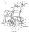
- FIG. 1 is a perspective view of an electric wheelchair according to an embodiment
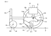
- FIG. 2 is a diagram of a drive unit disposed on the right side of a vehicle body as viewed from the center in the left-right direction of the vehicle body
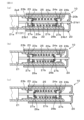
- FIG. 3 is a cross-sectional view of a first operating unit
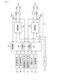
- FIG. 4 is a block diagram showing an example of a configuration for controlling the operation of a motor in an electric wheelchair
- FIG. 5 is a diagram for explaining a control logic of the drive mechanism by the control device
- FIG. 6 is a diagram showing a schematic view of a state in which an operator operates an electric wheelchair
- FIG. 1 is a perspective view of an electric wheelchair according to an embodiment
- FIG. 2 is a diagram of a drive unit disposed on the right side of a vehicle body as viewed from the center in the left-right direction of the vehicle body
- FIG. 3 is a cross-sectional view of a first operating unit
- FIG. 4 is a block diagram showing an example of a configuration for controlling the operation of
- FIG. 7 is a flowchart showing a process executed by the control device;
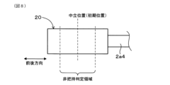
- FIG. 8 is a diagram for explaining a non-grip determination region of a grip;
- FIG. 9 is a flowchart showing a non-grasping determination process in FIG.
- FIG. 10 is a diagram showing a schematic view of a state in which an operator moves the electric wheelchair backward;
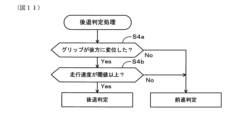
- FIG. 11 is a flowchart showing the reverse motion determination process in FIG. 7 .
- FIG. 12 is a diagram showing a schematic view of a state in which an operator operates an electric wheelchair to overcome a step;
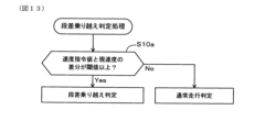
- FIG. 13 is a flowchart showing the step clearance determination process in FIG.
- the electric wheelchair 1 comprises a wheelchair section 2, a drive mechanism 4, a control box 6, a first operating section 10, and a second operating section 12.
- the wheelchair section 2 is a typical wheelchair, and comprises a vehicle body 2a mainly composed of a frame such as a metal pipe, a pair of main wheels 2b, and a pair of casters 2c.
- the pair of casters 2c are provided on both the left and right sides of the vehicle body 2a.
- the pair of main wheels 2b are also provided on both the left and right sides of the vehicle body 2a.
- the pair of main wheels 2b are provided behind the pair of casters 2c. Therefore, the pair of main wheels 2b are rear wheels.
- the pair of casters 2c are front wheels.
- the vehicle body 2a has a seat portion 2a1 on which a passenger sits, and a backrest portion 2a2.
- the vehicle body 2a has a pair of left and right support pipes 2a3.
- the pair of support pipes 2a3 support the backrest portion 2a2.
- a pair of protrusions 2a4 is provided on the upper ends of the pair of support pipes 2a3.
- the pair of protrusions 2a4 protrude rearward from the backrest portion 2a2.
- the pair of protrusions 2a4 are pipes having openings at their rear ends.
- a pair of first operating units 10 are provided on the pair of protrusions 2a4. Thus, the pair of first operating units 10 are disposed above the left and right sides of the backrest portion 2a2.
- the direction in which the passenger faces when riding in the electric wheelchair 1 (the direction in which the backrest portion 2a2 faces forward) is referred to as the forward direction, and the opposite direction is referred to as the rearward direction. Therefore, the passenger rides facing the front of the electric wheelchair 1. Additionally, the direction facing the left side as seen from the passenger's perspective is referred to as the leftward direction, and the direction facing the right side as seen from the passenger's perspective is referred to as the rightward direction.
- the drive mechanism 4 includes a pair of drive units 14.
- the pair of drive units 14 are fixed to the left and right sides of the vehicle body 2a.
- the pair of drive units 14 are disposed on the vehicle inward side of the pair of main wheels 2b.
- Each of the pair of left and right drive units 14 has a base plate 14a, an arm 14b, a drive wheel 14c, a motor 15, and a tipping bar 13.
- the base plate 14a is fixed to the frame of the vehicle body 2a. In this way, the drive unit 14 is attached to the wheelchair section 2.
- the tipping bar 13 is provided at the rear end of the base plate 14a.
- the tipping bar 13 is a member that is stepped on by the leg of an operator operating the electric wheelchair 1 from behind when the operator is climbing over a step. When the operator steps on the tipping bar 13, the caster 2c is lifted upward with the main wheel 2b as a fulcrum.
- the arm 14b is provided on the inside of the vehicle on the base plate 14a.
- the arm 14b is fixed to the base plate 14a so that it can swing up and down.
- the arm 14b can swing within a predetermined angular range.
- a motor 15 and a drive wheel 14c are provided at the tip of the arm 14b.
- the arm 14b supports the drive wheel 14c so that it can rotate freely.
- the arm 14b elastically biases the drive wheel 14c downward. As a result, the arm 14b presses the drive wheel 14c against the road surface to make it touch the ground.
- the motor 15 is an in-wheel motor and is provided inside the drive wheel 14c.
- the rotor (not shown) of the motor 15 can rotate integrally with the drive wheel 14c.
- the stator (not shown) of the motor 15 is fixed to the arm 14b side. This allows the motor 15 to drive and rotate the drive wheel 14c.
- the motor 15 is connected to a battery, a control device, etc. in the control box 6 via a cable (not shown).
- the cable is inserted into the arm 14b and connects the motor 15 and the control box 6.
- the control box 6 is fixed to the frame part on the lower right side of the seat portion 2a1.
- the control box 6 houses a battery, a control device that controls each part, etc.
- the drive wheels 14c are supported by the arm 14b so that they can rotate freely around a rotation axis C1 (see Figure 2) that is parallel to the left-right direction.
- the drive wheels 14c are driven to rotate by the motor 15 while in contact with the road surface.
- the pair of left and right motors 15 drive the pair of left and right drive wheels 14c, causing the wheelchair section 2 (vehicle body 2a) to move.
- the drive wheel 14c is disposed between the caster 2c and the main wheel 2b. More specifically, the position of the rotation axis C1 in the front-rear direction is between the rotation axis C2 of the caster 2c and the rotation axis C3 of the main wheel 2b. Therefore, the ground contact position t1 of the drive wheel 14c on the road surface F is located between the ground contact position t2 of the caster 2c and the ground contact position t3 of the main wheel 2b. It is sufficient that the ground contact position t1 of the drive wheel 14c is located in the range from the ground contact position t2 to the ground contact position t3. In other words, it is sufficient that the position of the rotation axis C1 in the front-rear direction is located in the range from the position of the rotation axis C2 to the position of the rotation axis C3.
- the first operation unit 10 has an operation detection unit 21 in addition to the grip 20.
- the grip 20 is attached to the tip of the protruding portion 2a4 on the left side of the vehicle.
- the grip 20 has a tubular portion 20a and a bottom portion 20b.
- the bottom portion 20b closes the rear opening of the tubular portion 20a.
- the tubular portion 20a is attached to the outer periphery of the protruding portion 2a4.
- the tubular portion 20a can move while sliding on the outer periphery of the protruding portion 2a4. Therefore, the grip 20 can move along the axial direction of the protruding portion 2a4.
- the protruding portion 2a4 extends along the front-rear direction. Therefore, the grip 20 can be held by the operator and can be displaced in the front-rear direction relative to the vehicle body 2a by the operator's operation.
- the operation detection unit 21 has a function of detecting the position and amount of displacement of the grip 20 in the forward/backward direction as displacement information of the grip 20 in the forward/backward direction.
- the operation detection unit 21 also has a function of detecting grip information of the grip 20 by the operator from the displacement information of the grip 20 in the forward/backward direction. Therefore, the operation detection unit 21 corresponds to a state sensor that detects the operation state or grip state of the operator with respect to the grip 20.
- the operation detection unit 21 is a potentiometer.
- the operation detection unit 21 is provided inside the protrusion 2a4.
- the operation detection unit 21 includes a main body 21a and a rod 21b.
- the main body 21a is fixed to the protrusion 2a4.
- the rod 21b extends rearward from the main body 21a.
- the rod 21b passes through the inside of the tube 20a and the protrusion 2a4.
- the rod 21b is movable in the axial direction relative to the main body 21a.
- the operation detection unit 21 detects and outputs the amount of displacement of the rod 21b in the axial direction.
- the tip 21b1 of the rod 21b is fixed to the bottom 20b. Therefore, the rod 21b moves in the front-rear direction together with the grip 20.
- the operation detection unit 21 allows the operation detection unit 21 to detect the amount of displacement of the grip 20 in the front-rear direction relative to the vehicle main body 2a.
- the operation detection unit 21 is connected to a control device described later in the control box 6.
- the output of the operation detection unit 21 is provided to the control device.
- a sleeve 22 In addition to the above-mentioned operation detector 21, a sleeve 22, a front bush 23, a rear bush 24, and a spring 25 are provided inside the protruding portion 2a4.
- the sleeve 22 is a cylindrical member that is inserted into and fixed to the inner circumferential surface of the protruding portion 2a4.
- the front bush 23, the rear bush 24, and the spring 25 are disposed on the inner circumferential side of the sleeve 22.
- the front bush 23 has a cylindrical portion 23a and a bottom portion 23b.
- the cylindrical portion 23a is inserted into and fixed to the inner circumferential surface 22a of the sleeve 22.
- the bottom portion 23b is provided at the front opening of the cylindrical portion 23a.
- the bottom portion 23b has a central hole 23b1.
- the rod 21b is inserted into the central hole 23b1.
- the rear bush 24 has a cylindrical portion 24a and a bottom portion 24b.
- the cylindrical portion 24a is inserted into and fixed to the inner circumferential surface 22a of the sleeve 22.
- the bottom portion 24b is provided at the rear opening of the cylindrical portion 24a.
- the bottom portion 24b has a central hole 24b1.
- the rod 21b is inserted into the central hole 24b1.
- the spring 25 is disposed between the front bush 23 and the rear bush 24.
- the rod 21b passes through the front bush 23, the rear bush 24, and the spring 25.
- the rod 21b is provided with a front retainer 26a, a front retaining ring 27a, a rear retainer 26b, and a rear retaining ring 27b.
- the front retaining ring 27a is provided on the front side of the spring 25.
- the front retaining ring 27a is fixed to the rod 21b.
- the front retaining ring 27a is fitted into a circumferential groove provided in the rod 21b.
- the rear retaining ring 27b is provided on the rear side of the spring 25.
- the rear retaining ring 27b is also fixed to the rod 21b.
- the rear retaining ring 27b is fitted into a circumferential groove provided in the rod 21b.
- the rear retaining ring 27b can move together with the rod 21b in the axial direction.
- the front retaining ring 27a and the rear retaining ring 27b are fixed to the rod 21b at a fixed distance in the axial direction.
- Front retainer 26a, rear retainer 26b, and spring 25 are disposed between front retaining ring 27a and rear retaining ring 27b.
- Front retainer 26a and rear retainer 26b are annular members that are passed through rod 21b.
- Front retainer 26a and rear retainer 26b hold the front end face and rear end face of spring 25.
- Front retainer 26a is interposed between front bush 23 and the front end face of spring 25.
- Rear retainer 26b is interposed between rear bush 24 and the rear end face of spring 25.
- Neutral position of the grip 20 (a) in Fig. 3 shows the case where the grip 20 is in the neutral position.
- the grip 20 is in the neutral position when it is not being held by the operator or when the operator is not inputting an operating force.
- the spring 25 biases the front retainer 26a toward the front bush 23.
- the spring 25 also biases the rear retainer 26b toward the rear bush 24.
- the front retainer 26a abuts against the cylindrical portion 23a of the front bush 23.
- the rear retainer 26b abuts against the cylindrical portion 24a of the rear bush 24.
- the distance between the front retainer 26 a and the rear retainer 26 b is shorter than the free length of the spring 25 .
- Front Position of Grip 20 (b) in FIG. 3 shows a case where the grip 20 moves to a front position forward of the neutral position.
- the rod 21b also moves forward. This causes the output of the operation detection unit 21 to change.
- the spring 25 is pressed forward by the rear retainer 26b and the rear stop ring 27b. Therefore, the rear retainer 26b moves away from the rear bush 24.
- the front stop ring 27a abuts against the bottom 23b of the front bush 23, as shown in (b) in FIG. 3. As a result, the front stop ring 27a and the front bush 23 restrict the forward movement of the rod 21b.
- Rear position of the grip 20 (c) in FIG. 3 shows a case where the grip 20 moves to a rear position rearward from the neutral position.
- the rod 21b also moves rearward. This causes the output of the operation detection unit 21 to change.
- the spring 25 is pressed rearward by the front retainer 26a and the front stop ring 27a. Therefore, the front retainer 26a moves away from the front bush 23.
- the rear stop ring 27b abuts against the bottom 24b of the rear bush 24, as shown in (c) in FIG. 3. As a result, the rear stop ring 27b and the rear bush 24 restrict the rearward movement of the rod 21b.
- the grip 20 can be elastically moved in the front-rear direction around the neutral position by the spring 25.
- the range of movement of the grip 20 and rod 21b in the front-rear direction is limited by the front bush 23, the rear bush 24, the front retaining ring 27a, and the rear retaining ring 27b.
- the electric wheelchair 1 further includes left and right drive speed sensors 17, an inertial sensor 8, a battery 16, and a control device 18.
- the inertial sensor 8, the battery 16, and the control device 18 are all housed in the control box 6 (see Fig. 1).
- the drive speed sensor 17 is for detecting the drive speed of the drive wheel 14c.
- the drive speed sensor 17 is attached to the drive wheel 14c.
- the drive speed sensor 17 is electrically connected to the control device 18. Therefore, the output of the drive speed sensor 17 is provided to the control device 18.
- the running speed of the vehicle body 2a of the electric wheelchair 1 can be calculated from the drive speed of the drive wheel 14c. Therefore, the drive speed sensor 17 can be said to be a running speed detection unit that detects the running speed of the vehicle body 2a of the electric wheelchair 1.
- the inertial sensor 8 is for detecting information related to the inertia acting on the vehicle body 2a.
- the inertial sensor 8 is, for example, an IMU (Inertial Measurement Unit) and includes at least a three-axis acceleration sensor.
- the inertial sensor 8 is electrically connected to the control device 18. Therefore, the output of the inertial sensor 8 is provided to the control device 18.
- the control device 18 determines the longitudinal tilt angle of the vehicle body 2a based on the output of the inertial sensor 8. In other words, the inertial sensor 8 functions as a sensor for detecting the longitudinal tilt angle of the vehicle body 2a.
- the battery 16 supplies power to the pair of motors 15 and to each component that requires operating power.
- the control device 18 has the function of controlling the drive mechanism 4 (pair of motors 15) by providing command values to the drive mechanism 4, and thus controlling the speed of the vehicle body 2a.
- the drive mechanism 4 including the pair of motors 15 has a pair of drive circuits 34.
- Each of the pair of motors 15 includes a motor body 15a and a rotation detector 15b.
- the motor body 15a includes the main components of a motor, such as a rotor and a stator.
- the rotation detector 15b is, for example, a Hall sensor provided on the motor body 15a.
- the rotation detector 15b detects the rotation angle of the rotor of the motor body 15a.
- the rotation detector 15b is connected to the drive circuit 34 and the control device 18. Therefore, the output of the rotation detector 15b is given to the drive circuit 34 and the control device 18. At this time, the rotation speed of the motor 15 is derived from the rotation angle of the rotor of the motor body 15a.
- the rotation detector 15b functions as a motor information detection unit that detects motor information related to the rotation speed of the motor 15.
- the motor information detected by the rotation detector 15b is also information related to the rotation of the drive wheel 14c. Therefore, the rotation detector 15b can also be called a rotation information detection unit that detects information related to the rotation of the drive wheel 14c.
- the pair of drive circuits 34 are, for example, inverters.
- the pair of drive circuits 34 may be housed in the control box 6, or may be provided on the base plate 14a or the arm 14b.
- the pair of drive circuits 34 are connected to the control device 18, the battery 16, and the pair of motors 15.
- the pair of drive circuits 34 provide power from the battery 16 to the pair of motors 15.
- the pair of drive circuits 34 have the function of providing drive power to the pair of motors 15 based on a speed command value provided by the control device 18 and the output of the rotation detector 15b, and controlling the motors 15 to rotate at the speed indicated by the speed command value.
- the pair of drive circuits 34 and the pair of motors 15 are connected by a pair of power lines 34a.
- the pair of power lines 34a are provided with a pair of current detection units 36.
- the pair of current detection units 36 are current sensors that detect the current flowing through the pair of power lines 34a. In other words, the pair of current detection units 36 detect the motor current flowing through the pair of motors 15.
- the pair of current detection units 36 are connected to the control device 18. Therefore, the output of the pair of current detection units 36 is provided to the control device 18.
- the pair of first operating unit 10 and second operating unit 12 are also connected to the control device 18. As described above, the output of the first operating unit 10 (i.e., the output of the operation detection unit 21) and the output of the second operating unit 12 are provided to the control device 18. In this embodiment, the outputs of the pair of operation detection units 21 are defined as operation inputs of the pair of grips 20 to the control device 18.
- the control device 18 is configured by a computer or the like that includes a processing unit 38 consisting of a processor or the like, and a storage unit 40 consisting of a memory, a hard disk, or the like.
- the storage unit 40 stores computer programs to be executed by the processing unit 38 and necessary information.
- the processing unit 38 realizes the various processing functions of the control device 18 by executing computer programs stored in a computer-readable, non-transitory recording medium such as the storage unit 40.
- control device 18 controls the drive mechanism 4 in accordance with the control logic shown in FIG.
- Impedance control and generation of a rotation speed command value are performed based on the operation input of the pair of grips 20.
- impedance control a spring-damper model, which will be described later, is used.
- a basic propulsive force is calculated based on the sum of the operation inputs of the pair of grips 20.
- a rotation speed command value is generated based on the difference between the operation inputs of the pair of grips 20.
- a total propulsive force is calculated by subtracting the external force and the braking force from the basic propulsive force.
- the external force is calculated based on the motor current detected by the current detection unit 36 (see Figure 4).
- the braking force is calculated using the driving speed.
- the driving speed is calculated from the driving speed detected by the driving speed sensor 17 (see Figure 4).
- a speed command value for the motor 15 is generated based on the total propulsive force and the turning speed torque.
- the turning torque is calculated based on the turning speed command value and the yaw rate.
- the yaw rate is calculated based on the drive speed of the drive wheels 14c and the wheel spacing between the pair of drive wheels 14c.
- the speed control of the motor 15 is executed based on the generated speed command value and the drive speed of the drive wheels 14c.
- a known PID control can be used to improve responsiveness.
- PID control adds feedback control of integral action (I control) and feedback control of differential action (D control) to control (P control) that performs adjustment proportional to the deviation between the current output value and the target value.
- control device 18 Based on the output provided by the pair of first operating units 10, control device 18 generates a speed command value for motor 15 and provides it to a pair of drive circuits 34. In this way, control device 18 controls motor 15.
- the motor 15 When operator A grips the grip 20 and pushes it forward, the motor 15 is controlled so that the drive wheel 14c assists the forward movement of the electric wheelchair 1. When operator A grips the grip 20 and pulls it backward, the motor 15 is controlled so that the drive wheel 14c assists the backward movement of the electric wheelchair 1. On the other hand, when operator A is in a non-gripping state where he is not gripping the grip 20, or when operator A does not operate the grip 20 in the forward or backward direction from the neutral position, the motor 15 is controlled so as not to drive the drive wheel 14c.
- control device 18 determines whether operator A is in an operating state or a non-operating state with respect to the grip 20, or whether operator A is in a gripping state or a non-gripping state with respect to the grip 20, and controls the motor 15 according to the operating state or the non-operating state, or according to the gripping state or the non-gripping state.
- the output from the pair of first operating units 10 indicates the amount of longitudinal displacement of the pair of grips 20 relative to the vehicle body 2a.
- the control device 18 determines the amount of longitudinal displacement of each of the pair of grips 20 based on the output from the pair of first operating units 10. Note that this amount of displacement is the distance between a reference position (e.g., neutral position) that is preset within the movable range of the grips 20 and the current position of the grips 20. When the reference position and the current position coincide in the longitudinal direction, the amount of displacement is 0 (zero).
- the control device 18 discretely acquires the amount of displacement of the grips 20 over time and stores it in the memory unit 40.
- control device 18 controls drive mechanism 4 so that the movement of vehicle body 2a in response to the amount of displacement mimics mechanical impedance characteristics. That is, as shown in FIG. 6, control device 18 controls drive mechanism 4 so that distance H between grip 20 and vehicle body 2a is constant while reproducing a movement in which grip 20 and vehicle body 2a are connected by virtual spring 42 and virtual damper 44.
- a spring-damper model using virtual spring 42 and damper 44 is used for impedance control (see FIG. 5).
- Control of the drive mechanism 4 so that the distance H between the grip 20 and the vehicle body 2a is constant includes control to maintain the amount of displacement at 0 (zero) or a predetermined set value.
- the control device 18 controls the drive mechanism 4 to move the vehicle body 2a forward according to the amount of displacement of the grip 20. For example, when operator A moves forward and the grip 20 is pressed forward, the control device 18 controls the drive mechanism 4 to move the vehicle body 2a forward. Conversely, when operator A moves backward and the grip 20 is pulled backward, the control device 18 controls the drive mechanism 4 to move the vehicle body 2a backward. Also, when the position of the grip 20 is in the reference position (neutral position), the control device 18 controls the drive mechanism 4 to stop the vehicle body 2a.
- processing unit 38 of the control device 18 sequentially executes processing from step S1 to step S15 for controlling the drive mechanism 4.
- the grip 20 being in a gripped or non-grip state is essentially the same as the grip 20 being in an operated or non-operated state. That is, the operator operates the grip 20 while gripping the grip 20, whereas the operator releases the grip of the grip 20 when releasing the operation of the grip 20.
- “non-grip judgment” and “grip judgment” are also referred to as “non-operation judgment” and “operation judgment”, respectively
- “non-grip state” and “grip state” are also referred to as “non-operation state” and “operation state”, respectively.
- Non-Grip Determination Process Step S1 in FIG. 1 is a step for performing a non-grip determination process for the grip 20.
- This non-grip determination process is a non-operation determination process.
- a non-grip determination region is set for the grip 20.
- the non-grip determination region includes the neutral position (see (a) in FIG. 3), which is the initial position of the grip 20.
- This non-grip determination region is a non-operation determination region.
- step S1 in FIG. 7 includes steps S1a and S1b.
- Step S1a is a step for determining whether or not the grip 20 is within the non-grasping judgment area. If the grip 20 is within the non-grasping judgment area ("Yes” at step S1a), the process proceeds to step S1b. On the other hand, if the grip 20 is not within the non-grasping judgment area ("No” at step S1a), a "grasping judgment” is made that the grip 20 is in a gripping state. This gripping judgment is also an "operation judgment” that the grip 20 is in an operating state.
- Step S1b is a step for determining whether or not the displacement speed of the grip 20 is equal to or less than a threshold value. If the displacement speed of the grip 20 is equal to or less than the threshold value ("Yes” in step S1b), a “non-grasping determination” is made that the grip 20 is in an ungrasped state. This non-grasping determination is also a "non-operation determination” that the grip 20 is in an unoperated state. On the other hand, if the displacement speed of the grip 20 exceeds the threshold value ("No” in step S1b), a "grasping determination” is made that the grip 20 is in a gripped state.
- the threshold value used in step S1b is pre-stored in the memory unit 40.
- step S2 is a step for detecting whether or not the grip 20 is in an ungrasped state based on the result of the ungrasped determination process in step S1. If the grip 20 is in an ungrasped state ("Yes” in step S2), the process proceeds to step S3. On the other hand, if the grip 20 is not in an ungrasped state ("No" in step S2), the process proceeds to step S4. This step S2 is the starting point for switching the control parameters for the drive mechanism 4.
- Step S3 is a step for setting the grip 20 to the neutral position. According to this step S3, the amount of displacement of the grip 20 from the neutral position becomes 0 (zero). After executing step S3, the process proceeds to step S7.
- Step S4 is a step for performing the reverse determination process. That is, the reverse determination process in step S4 is executed in a gripping state in which the grip 20 is gripped by the operator A.
- a state in which the grip 20 is gripped by the operator A and the electric wheelchair 1 is reversing on the road surface F together with the operator A is referred to as "reverse".
- step S4 in FIG. 7 includes steps S4a and S4b.
- Step S4a is a step for determining whether or not the grip 20 has been displaced backward. If the grip 20 has been displaced backward ("Yes” at step S4a), the process proceeds to step S4b. On the other hand, if the grip 20 has not been displaced backward ("No” at step S4a), a "forward movement determination" is made to determine that the electric wheelchair 1 is in a forward movement state.
- Step S4b is a step for determining whether the traveling speed of the vehicle body 2a of the electric wheelchair 1 is equal to or higher than a threshold value.
- the traveling speed of the vehicle body 2a is calculated from the driving speed detected by the driving speed sensor 17 (see FIG. 4).
- the traveling speed is always a positive value regardless of whether the electric wheelchair 1 is in a forward or backward state. That is, when the electric wheelchair 1 is moving forward, the traveling speed is calculated with the forward direction as positive, and when the electric wheelchair 1 is moving backward, the traveling speed is calculated with the backward direction as positive.
- step S4b If the traveling speed is equal to or higher than the threshold value (if "Yes” in step S4b), a “backward determination” is made that the vehicle body 2a of the electric wheelchair 1 is in a backward state. On the other hand, if the traveling speed is lower than the threshold value (if "NO” in step S4b), a “forward determination” is made that the vehicle body 2a of the electric wheelchair 1 is in a forward state.
- the threshold value used in step S4b is prestored in the memory unit 40.
- step S5 is a step for detecting whether or not the electric wheelchair 1 is in a backward movement state based on the result of the backward movement determination process in step S4. If the electric wheelchair 1 is in a forward movement state (if "No” in step S5), the process proceeds to step S7.
- Step S6 is a step for setting control parameters for backward movement if the electric wheelchair 1 is in a backward movement state (if "Yes” in step S5). After executing step S6, the process proceeds to step S7.
- Step S7 is a step for calculating the input torque that the motor 15 inputs to the drive wheel 14c.
- step S7 if the electric wheelchair 1 is in a forward movement state, the input torque is calculated based on the forward movement control parameters, and if the electric wheelchair 1 is in a backward movement state, the input torque is calculated based on the backward movement control parameters.
- Step S8 is a step for generating a speed command value for the motor 15 using the input torque calculated in step S7.
- Step S9 is a step for determining whether or not the traveling speed of the vehicle body 2a of the electric wheelchair 1 is within the assist range. If the traveling speed is within the assist range ("Yes” at step S9), proceed to step S10. On the other hand, if the traveling speed is not within the assist range ("No" at step S9), i.e., if the traveling speed exceeds the assist range, proceed to step S14.
- Step S14 is a step for setting the motor 15 to the servo-off state.
- the motor 15 is set to the servo-off state, the assistance of the drive wheels 14c in the movement of the electric wheelchair 1 is released.
- step S15 is a step for replacing the speed command value for the motor 15 with the current speed of the motor 15.
- step S13 the process proceeds to step S13.
- Step S10 is a step for performing step-crossing determination process.
- the operation of the electric wheelchair 1 by the operator A so that the electric wheelchair 1 crosses a step is referred to as a "step-crossing operation" in this step-crossing determination process.
- This step-crossing operation is shown in stages, for example, by (a) to (c) in FIG. 12.
- Step S10a is a step in which a speed command value for the motor 15 and the current speed of the motor 15 are used to determine whether or not the difference between the speed command value and the current speed is equal to or greater than a threshold value.
- the current speed of the motor 15 is derived from the rotation angle of the rotor of the motor body 15a detected by the rotation detector 15b. If the difference between the speed command value and the current speed is equal to or greater than the threshold value (if "Yes" in step S10a), the drive wheel 14c has transitioned from a ground contact free spin state to a ground contact state (see (c) in FIG.
- step S10a a "normal running determination” is made that the electric wheelchair 1 is in a normal running state.
- the threshold value used in step S10a is pre-stored in the memory unit 40.
- a drive speed sensor 17 may be used in addition to detecting the drive speed of the drive wheel 14c.
- step S11 is a step for detecting whether or not the electric wheelchair 1 is in a step-climbing state based on the result of the step-climbing determination process in step S10. If the electric wheelchair 1 is in a step-climbing state ("Yes" in step S11), the process proceeds to step S12. On the other hand, if the electric wheelchair 1 is not in a step-climbing state ("No" in step S11), the process proceeds to step S13.
- Step S12 is a step in which the speed command value for the motor 15 is replaced with the current speed of the motor 15. According to this step S12, immediately after it is determined that the drive wheel 14c has transitioned from a non-grounded spinning state to a grounded state, the control of the motor 15 is switched from a normal driving mode based on the position of the grip 20 to a grounded transition mode that is not based on the position of the grip 20. After executing step S12, the process proceeds to step S13. Step S13 is a step in which the currently set speed command value is output.
- the control device 18 determines whether the operator A is in an operating state or a non-operating state with respect to the grip 20, or whether the operator A is in a gripping state or a non-gripping state with respect to the grip 20. The control device 18 then controls the motor 15 according to the operating state or the non-operating state, or according to the gripping state or the non-gripping state. Therefore, by grasping the state of the operator A with respect to the electric wheelchair 1 and controlling the motor 15 according to that state, the safety of the electric wheelchair 1 can be improved.
- the control device 18 determines whether the vehicle body 2a is in a forward or backward state, and controls the motor 15 according to the forward or backward state.
- the drive direction of the drive wheels 14c in the forward state corresponds to the direction in which the electric wheelchair 1 moves away from the operator A.
- the drive direction of the drive wheels 14c in the backward state corresponds to the direction in which the electric wheelchair 1 moves toward the operator A.
- the drive direction of the drive wheels 14c in the forward and backward states is different with respect to the positional relationship between the operator A and the electric wheelchair 1. Therefore, by determining whether the vehicle body 2a is in a forward or backward state and controlling the motor 15 according to that state, good operability can be achieved for the operator A.
- the control device 18 determines that the drive wheels 14c have transitioned from a non-grounded spinning state to a grounded state, and immediately after the drive wheels have transitioned from a non-grounded spinning state to a grounded state, the control of the motor 15 is switched from a normal driving mode based on the position of the grip 20 to a grounded transition mode that is not based on the position of the grip 20. This makes it possible to improve operability immediately after the drive wheels 14c transition to a grounded state when going over a step.
- the operation detection unit 21 is used to perform the non-grasping determination, but a means other than the operation detection unit 21 may be used.
- An example of the other means is a pressure sensor provided in the grip 20. For example, when the pressure detected by the pressure sensor is below a threshold, it can be determined that the state is non-grasping, and when the pressure is equal to or greater than the threshold, it can be determined that the state is gripping.
- a means other than the operation detection unit 21 may be used.
- An example of such a means is a distance measurement sensor that can measure distance, such as an ultrasonic sensor. If the distance measurement sensor is used to detect the amount of rearward displacement of the grip 20, this amount of displacement can be used in the determination of whether the vehicle is moving backward.
- the rotation detector 15b is used to determine whether or not a step has been crossed, but a means other than the rotation detector 15b may be used.
- An example of such a means is a load cell that can detect a load. If the load applied to the drive wheel 14c is detected using a load cell, this load can be used to determine whether or not the step has been crossed.
Landscapes
- Health & Medical Sciences (AREA)
- Life Sciences & Earth Sciences (AREA)
- Animal Behavior & Ethology (AREA)
- General Health & Medical Sciences (AREA)
- Public Health (AREA)
- Veterinary Medicine (AREA)
- Handcart (AREA)
Abstract
電動車椅子(1)は、車両本体(2a)と、車両本体(2a)を走行させる駆動輪(14c)と、駆動輪(14c)を駆動するモータ(15)と、操作者により把持可能であり車両本体(2a)の前後方向に変位可能なグリップ(20)と、操作者のグリップ(20)に対する操作状態または把持状態を検出する状態センサ(21)と、モータ(15)を制御する制御装置(18)と、を備え、制御装置(18)は、操作者がグリップ(20)に対して操作状態と非操作状態のいずれの状態であるか、又は、操作者がグリップ(20)に対して把持状態と非把持状態のいずれの状態であるかを判定し、操作状態と非操作状態に応じて、又は、把持状態と非把持状態に応じて、モータ(15)を制御する。
Description
本開示は、電動車椅子に関する。
下記特許文献1には、操作者の操作に応じた推進力を付与するように構成された電動車椅子が記載されている。当該電動車椅子においては、操作者が把持するグリップが前後方向に移動可能に設けられており、グリップの変位に応じて推進力を付与する。
電動車椅子において、操作者がグリップを把持している状態であれば操作者が電動車椅子を操作できるが、把持していない状態では操作者が電動車椅子を操作できない。そこで、操作者がグリップを把持していない状態において、電動車椅子の安全性を高めることが求められる。
また、電動車椅子において、前進状態及び後退状態において駆動輪に対して同一の制御を行うと、操作者が操作しにくいと感じるおそれがある。また、路面の段差を乗り越える場合には、操作者が前輪を路面から浮かせて前進させ、その後に前輪を接地させる。この場合、駆動輪が路面から非接地状態となった後に接地状態となることがある。この間、駆動輪に対して同一の制御を行うと、操作者が操作しにくいと感じるおそれがある。
従って、電動車椅子の状態を把握することは、安全性及び操作性の観点から重要である。しかし、特許文献1には、電動車椅子の状態を把握することまで記載されていない。
本開示は、かかる課題に鑑みてなされたものであり、安全性又は操作性を向上することができる電動車椅子を提供しようとするものである。
本開示の一態様は、
車両本体と、
前記車両本体を走行させる駆動輪と、
前記駆動輪を駆動するモータと、
操作者により把持可能であり前記操作者の操作により前記車両本体の前後方向に変位可能なグリップと、
前記操作者の前記グリップに対する操作状態または把持状態を検出する状態センサと、
前記モータを制御する制御装置と、
を備え、
前記制御装置は、前記操作者が前記グリップに対して操作状態と非操作状態のいずれの状態であるか、又は、前記操作者が前記グリップに対して把持状態と非把持状態のいずれの状態であるかを判定し、前記操作状態と前記非操作状態に応じて、又は、前記把持状態と前記非把持状態に応じて、前記モータを制御する、電動車椅子、
にある。
車両本体と、
前記車両本体を走行させる駆動輪と、
前記駆動輪を駆動するモータと、
操作者により把持可能であり前記操作者の操作により前記車両本体の前後方向に変位可能なグリップと、
前記操作者の前記グリップに対する操作状態または把持状態を検出する状態センサと、
前記モータを制御する制御装置と、
を備え、
前記制御装置は、前記操作者が前記グリップに対して操作状態と非操作状態のいずれの状態であるか、又は、前記操作者が前記グリップに対して把持状態と非把持状態のいずれの状態であるかを判定し、前記操作状態と前記非操作状態に応じて、又は、前記把持状態と前記非把持状態に応じて、前記モータを制御する、電動車椅子、
にある。
本開示の他の態様は、
車両本体と、
前記車両本体を走行させる駆動輪と、
前記駆動輪を駆動するモータと、
操作者により把持可能であり前記操作者の操作により前記車両本体の前後方向に変位可能なグリップと、
前記グリップの前記前後方向の位置を検出する操作検出部と、
前記操作検出部が検出した前記位置に基づいて前記モータを制御する制御装置と、
を備え、
前記制御装置は、前記車両本体が前進状態と後退状態のいずれの状態であるかを判定し、前記前進状態と前記後退状態に応じて前記モータを制御する、電動車椅子、
にある。
車両本体と、
前記車両本体を走行させる駆動輪と、
前記駆動輪を駆動するモータと、
操作者により把持可能であり前記操作者の操作により前記車両本体の前後方向に変位可能なグリップと、
前記グリップの前記前後方向の位置を検出する操作検出部と、
前記操作検出部が検出した前記位置に基づいて前記モータを制御する制御装置と、
を備え、
前記制御装置は、前記車両本体が前進状態と後退状態のいずれの状態であるかを判定し、前記前進状態と前記後退状態に応じて前記モータを制御する、電動車椅子、
にある。
本開示のさらなる他の態様は、
車両本体と、
前記車両本体を走行させる駆動輪と、
前記駆動輪を駆動するモータと、
操作者により把持可能であり前記操作者の操作により前記車両本体の前後方向に移動可能なグリップと、
前記グリップの前後方向の位置を検出する操作検出部と、
前記駆動輪の回転に関する情報を検出する回転情報検出部と、
前記操作検出部が検出した前記位置に基づいて前記モータを制御する制御装置と、
を備え、
前記駆動輪は、駆動時において接地状態と非接地空転状態とを取り得るように構成されており、
前記制御装置は、前記回転情報検出部が検出した前記情報に基づいて前記駆動輪が前記非接地空転状態から前記接地状態に移行したことを判定した場合、その判定直後に前記モータの制御を、前記グリップの前記位置に基づく通常走行モードから、前記グリップの前記位置に基づかない接地移行モードに切り替える、電動車椅子、
にある。
車両本体と、
前記車両本体を走行させる駆動輪と、
前記駆動輪を駆動するモータと、
操作者により把持可能であり前記操作者の操作により前記車両本体の前後方向に移動可能なグリップと、
前記グリップの前後方向の位置を検出する操作検出部と、
前記駆動輪の回転に関する情報を検出する回転情報検出部と、
前記操作検出部が検出した前記位置に基づいて前記モータを制御する制御装置と、
を備え、
前記駆動輪は、駆動時において接地状態と非接地空転状態とを取り得るように構成されており、
前記制御装置は、前記回転情報検出部が検出した前記情報に基づいて前記駆動輪が前記非接地空転状態から前記接地状態に移行したことを判定した場合、その判定直後に前記モータの制御を、前記グリップの前記位置に基づく通常走行モードから、前記グリップの前記位置に基づかない接地移行モードに切り替える、電動車椅子、
にある。
本開示の一態様によれば、制御装置が、操作者がグリップに対して操作状態と非操作状態のいずれの状態であるか、又は、操作者がグリップに対して把持状態と非把持状態のいずれの状態であるかを判定している。そして、制御装置が、操作状態と非操作状態に応じて、又は、把持状態と非把持状態に応じて、モータを制御する。従って、電動車椅子に対する操作者の状態を把握して、その状態に応じてモータを制御することにより、電動車椅子の安全性を高めることができる。
また、本開示の他の態様によれば、制御装置が、車両本体が前進状態と後退状態のいずれの状態であるかを判定し、前進状態と後退状態に応じてモータを制御する。前進状態における駆動輪の駆動方向は、操作者に対して、電動車椅子が遠ざかる方向に一致する。一方、後退状態における駆動輪の駆動方向は、操作者に対して、電動車椅子が近づく方向に一致する。このように、前進状態と後退状態では、操作者と電動車椅子との位置関係に対する駆動輪の駆動方向が異なる。そこで、車両本体が前進状態と後退状態とのいずれであるかを把握して、その状態に応じてモータを制御することにより、操作者に対して操作性を良好とすることができる。
また、本開示のさらなる他の態様によれば、制御装置が、駆動輪が非接地空転状態から接地状態に移行したことを判定し、駆動輪が非接地空転状態から接地状態に移行した直後において、モータの制御を、グリップの位置に基づく通常走行モードから、グリップの位置に基づかない接地移行モードに切り替える。例えば、段差乗り越え時に、駆動輪が非接地空転状態から接地状態に移行する。このような場合に、制御装置が当該状態を把握して、その状態に応じてモータを制御することにより、駆動輪が接地状態に移行した直後における操作性を良好とすることができる。
以上のごとく、上述の態様によれば、安全性又は操作性を向上することができる電動車椅子を提供することができる。
なお、請求の範囲に記載した括弧内の符号は、後述する実施形態に記載の具体的手段との対応関係を示すものであり、本開示の技術的範囲を限定するものではない。
本開示についての上記目的およびその他の目的、特徴や利点は、添付の図面を参照しながら説明する下記の詳細な記述により、より明確になる。その図面は、
図1は、実施形態に係る電動車椅子の斜視図であり、
図2は、車両本体の右側に配置される駆動ユニットを車両本体の左右方向中央からみたときの図であり、
図3は、第1操作部の断面図であり、
図4は、電動車椅子における、モータの動作制御を行うための構成例を示すブロック図であり、
図5は、制御装置による駆動機構の制御ロジックを説明するための図であり、
図6は、操作者が電動車椅子を操作するときの様子を模式的に示す図であり、
図7は、制御装置が実行する処理を示すフローチャートであり、
図8は、グリップの非把持判定領域を説明するための図であり、
図9は、図7中の非把持判定処理を示すフローチャートであり、
図10は、操作者が電動車椅子を後退させるときの様子を模式的に示す図であり、
図11は、図7中の後退判定処理を示すフローチャートであり、
図12は、操作者による電動車椅子の段差乗り越え操作時の様子を模式的に示す図であり、
図13は、図7中の段差乗り越え判定処理を示すフローチャートである。
以下、上述の態様の一実施形態である電動車椅子について、図面を参照しつつ説明する。
(実施形態)
1.電動車椅子1の全体構造
図1に示されるように、実施形態の電動車椅子1は、操作者による操作によって走行する電動車両である。この電動車椅子1の走行は、電動駆動式の駆動輪14cによって補助される。
1.電動車椅子1の全体構造
図1に示されるように、実施形態の電動車椅子1は、操作者による操作によって走行する電動車両である。この電動車椅子1の走行は、電動駆動式の駆動輪14cによって補助される。
電動車椅子1は、車椅子部2と、駆動機構4と、コントロールボックス6と、第1操作部10と、第2操作部12と、を備える。車椅子部2は、一般的な車椅子であり、主に金属製のパイプ等のフレームで構成された車両本体2aと、一対の主輪2bと、一対のキャスタ2cと、を備える。一対のキャスタ2cは、車両本体2aの左右両側に設けられている。一対の主輪2bも、車両本体2aの左右両側に設けられている。一対の主輪2bは、一対のキャスタ2cの後方に設けられている。よって、一対の主輪2bは後輪である。また、一対のキャスタ2cは前輪である。
車両本体2aは、搭乗者が着座する座部2a1と、背もたれ部2a2と、を有する。車両本体2aは、左右一対の支持パイプ2a3を有する。一対の支持パイプ2a3は、背もたれ部2a2を支持する。一対の支持パイプ2a3の上端には、一対の突出部2a4が設けられている。一対の突出部2a4は、背もたれ部2a2から後方に突出している。一対の突出部2a4は、後端に開口を有するパイプである。一対の第1操作部10は、一対の突出部2a4に設けられている。よって、一対の第1操作部10は、背もたれ部2a2の左右上方に配置されている。一対の第1操作部10は、それぞれ、グリップ20を有する。第2操作部12は、右側の突出部2a4に設けられている。第2操作部12には、操作者の操作を受け付けるための複数の操作スイッチ12aが設けられている。複数の操作スイッチ12aには、電源をオンオフするための操作スイッチと、駆動機構4の状態を、電動車椅子1の動作のアシストを開始した状態と、当該アシストを終了した状態と、の間で切り替えるための操作スイッチと、が含まれている。
以下の説明では、搭乗者が電動車椅子1に乗車したときに当該搭乗者の正面が向く方向(背もたれ部2a2が正面を向く方向)を前方向、その反対方向を後方向とする。よって、搭乗者は、電動車椅子1の前方を向いて乗車する。また、搭乗者から見て左側へ向く方向を左方向、搭乗者から見て右側へ向く方向を右方向とする。
駆動機構4は、一対の駆動ユニット14を含む。一対の駆動ユニット14は、車両本体2aの左右に固定されている。一対の駆動ユニット14は、一対の主輪2bの車両内方側に配置されている。左右一対の駆動ユニット14は、それぞれ、ベースプレート14aと、アーム14bと、駆動輪14cと、モータ15と、ティッピングバー13と、を有する。
2.駆動ユニット14の構造
図1及び図2に示されるように、ベースプレート14aは、車両本体2aのフレームに固定される。これにより、駆動ユニット14は、車椅子部2に装着される。ティッピングバー13は、ベースプレート14aの後端に設けられている。ティッピングバー13は、電動車椅子1を後方から操作する操作者による段差乗り越え操作のときに操作者の脚によって踏み込まれる部材である。操作者がティッピングバー13を踏み込むことで、主輪2bを支点としてキャスタ2cが上方へ持ち上げられる。
図1及び図2に示されるように、ベースプレート14aは、車両本体2aのフレームに固定される。これにより、駆動ユニット14は、車椅子部2に装着される。ティッピングバー13は、ベースプレート14aの後端に設けられている。ティッピングバー13は、電動車椅子1を後方から操作する操作者による段差乗り越え操作のときに操作者の脚によって踏み込まれる部材である。操作者がティッピングバー13を踏み込むことで、主輪2bを支点としてキャスタ2cが上方へ持ち上げられる。
アーム14bは、ベースプレート14aの車両内方側に設けられている。アーム14bは、上下方向に揺動可能にベースプレート14aに固定されている。アーム14bは、所定の角度範囲で揺動可能である。アーム14bの先端部には、モータ15と、駆動輪14cとが設けられている。アーム14bは、駆動輪14cを回転自在に支持する。アーム14bは、駆動輪14cを下方向へ向けて弾性的に付勢している。これにより、アーム14bは、駆動輪14cを路面に押圧して接地させる。
モータ15は、インホイールモータであり、駆動輪14cの内部に設けられている。モータ15が有するロータ(図示省略)は、駆動輪14cと一体回転可能である。また、モータ15が有するステータ(図示省略)は、アーム14b側に固定される。これにより、モータ15は、駆動輪14cを回転駆動する。モータ15は、ケーブル(図示省略)を介してコントロールボックス6内のバッテリや制御装置等に接続されている。前記ケーブルは、アーム14b内に挿通され、モータ15とコントロールボックス6を繋ぐ。コントロールボックス6は、座部2a1の下方右側のフレーム部分に固定されている。コントロールボックス6には、バッテリや各部を制御する制御装置等が収容されている。
駆動輪14cは、左右方向に平行な回転軸C1(図2を参照)回りに回転自在にアーム14bに支持されている。駆動輪14cは、路面に接地した状態で、モータ15によって回転駆動される。左右一対のモータ15が左右一対の駆動輪14cを駆動することで、車椅子部2(車両本体2a)が走行する。
図2に示されるように、駆動輪14cは、キャスタ2cと主輪2bとの間に配置されている。より具体的には、前後方向における回転軸C1の位置は、キャスタ2cの回転軸C2と、主輪2bの回転軸C3との間である。よって、路面Fにおける駆動輪14cの接地位置t1は、キャスタ2cの接地位置t2と、主輪2bの接地位置t3との間に位置している。駆動輪14cの接地位置t1は、接地位置t2から接地位置t3までの範囲に位置していればよい。言い換えると、前後方向における回転軸C1の位置は、回転軸C2の位置から回転軸C3の位置までの範囲に位置していればよい。
3.第1操作部10の構造
図3中の(a)に示されるように、第1操作部10は、グリップ20の他、操作検出部21を有する。グリップ20は、車両左側の突出部2a4の先端部に装着されている。グリップ20は、筒部20aと、底部20bと、を有する。底部20bは、筒部20aの後方側の開口を塞いでいる。筒部20aは、突出部2a4の外周側に装着される。筒部20aは、突出部2a4の外周面をスライドしつつ移動可能である。よって、グリップ20は、突出部2a4の軸方向に沿って移動可能である。突出部2a4は、前後方向に沿って延びている。よって、グリップ20は、操作者により把持可能であり操作者の操作により車両本体2aに対して前後方向に変位可能である。
図3中の(a)に示されるように、第1操作部10は、グリップ20の他、操作検出部21を有する。グリップ20は、車両左側の突出部2a4の先端部に装着されている。グリップ20は、筒部20aと、底部20bと、を有する。底部20bは、筒部20aの後方側の開口を塞いでいる。筒部20aは、突出部2a4の外周側に装着される。筒部20aは、突出部2a4の外周面をスライドしつつ移動可能である。よって、グリップ20は、突出部2a4の軸方向に沿って移動可能である。突出部2a4は、前後方向に沿って延びている。よって、グリップ20は、操作者により把持可能であり操作者の操作により車両本体2aに対して前後方向に変位可能である。
操作検出部21は、グリップ20の前後方向の変位情報として、グリップ20の前後方向の位置及び変位量を検出する機能を有する。また、操作検出部21は、グリップ20の前後方向の変位情報から、操作者によるグリップ20の把持情報をも検出する機能を有する。このため、操作検出部21は、操作者のグリップ20に対する操作状態または把持状態を検出する状態センサに相当する。
本形態において、操作検出部21はポテンショメータである。操作検出部21は、突出部2a4の内部に設けられている。操作検出部21は、本体部21aと、ロッド21bと、を備える。本体部21aは、突出部2a4に固定されている。ロッド21bは、本体部21aから後方向に延びている。ロッド21bは、筒部20a及び突出部2a4の内部を通過する。ロッド21bは、本体部21aに対して軸方向に相対移動可能である。操作検出部21は、ロッド21bの軸方向の変位量を検出し出力する。ロッド21bの先端部21b1は、底部20bに固定されている。よって、ロッド21bはグリップ20と一体に前後方向に移動する。これにより、操作検出部21は、車両本体2aに対するグリップ20の前後方向の変位量を検出することができる。操作検出部21は、コントロールボックス6内の後述する制御装置に接続されている。操作検出部21の出力は、制御装置へ与えられる。
突出部2a4の内部には、上述の操作検出部21の他、スリーブ22と、前ブッシュ23と、後ブッシュ24と、スプリング25と、が設けられている。スリーブ22は、円筒状の部材であり、突出部2a4の内周面に挿入され、固定されている。前ブッシュ23、後ブッシュ24、及びスプリング25は、スリーブ22の内周側に配置されている。
前ブッシュ23は、円筒部23aと、底部23bと、を有する。円筒部23aは、スリーブ22の内周面22aに挿入され、固定されている。底部23bは、円筒部23aの前側の開口に設けられている。底部23bは、中心孔23b1を有する。中心孔23b1には、ロッド21bが挿通される。後ブッシュ24は、円筒部24aと、底部24bと、を有する。円筒部24aは、スリーブ22の内周面22aに挿入され、固定されている。底部24bは、円筒部24aの後側の開口に設けられている。底部24bは、中心孔24b1を有する。中心孔24b1には、ロッド21bが挿通される。
スプリング25は、前ブッシュ23と、後ブッシュ24との間に配置されている。よって、ロッド21bは、前ブッシュ23、後ブッシュ24、及びスプリング25を貫通している。ロッド21bには、前リテーナ26aと、前止め輪27aと、後リテーナ26bと、後止め輪27bと、が設けられている。前止め輪27aは、スプリング25の前側に設けられている。前止め輪27aは、ロッド21bに固定されている。前止め輪27aは、ロッド21bに設けられた周溝に嵌め込まれている。よって、前止め輪27aは、ロッド21bと軸方向に一体に移動可能である。後止め輪27bは、スプリング25の後側に設けられている。後止め輪27bも、ロッド21bに固定されている。後止め輪27bは、ロッド21bに設けられた周溝に嵌め込まれている。よって、後止め輪27bは、ロッド21bと軸方向に一体に移動可能である。つまり、前止め輪27aと、後止め輪27bとは、軸方向に一定の間隔を置いてロッド21bに固定されている。
前リテーナ26a、後リテーナ26b、及びスプリング25は、前止め輪27aと、後止め輪27bとの間に配置されている。前リテーナ26a及び後リテーナ26bは、ロッド21bに貫通された円環状の部材である。前リテーナ26a及び後リテーナ26bは、スプリング25の前端面及び後端面を保持する。前リテーナ26aは、前ブッシュ23とスプリング25の前端面との間に介在している。後リテーナ26bは、後ブッシュ24とスプリング25の後端面との間に介在している。
4.グリップ20の中立位置
図3中の(a)は、グリップ20が中立位置の場合を示している。グリップ20は、操作者に把持されていない状態のときや、操作者による操作力の入力がないときに、中立位置となる。グリップ20が中立位置の場合、スプリング25は、前リテーナ26aを前ブッシュ23へ向けて付勢する。また、スプリング25は、後リテーナ26bを後ブッシュ24へ向けて付勢する。このとき、前リテーナ26aは、前ブッシュ23の円筒部23aに当接する。また、後リテーナ26bは、後ブッシュ24の円筒部24aに当接する。
つまり、グリップ20が中立位置の場合、前リテーナ26aと後リテーナ26bとの間の間隔は、スプリング25の自由長よりも短い。
図3中の(a)は、グリップ20が中立位置の場合を示している。グリップ20は、操作者に把持されていない状態のときや、操作者による操作力の入力がないときに、中立位置となる。グリップ20が中立位置の場合、スプリング25は、前リテーナ26aを前ブッシュ23へ向けて付勢する。また、スプリング25は、後リテーナ26bを後ブッシュ24へ向けて付勢する。このとき、前リテーナ26aは、前ブッシュ23の円筒部23aに当接する。また、後リテーナ26bは、後ブッシュ24の円筒部24aに当接する。
つまり、グリップ20が中立位置の場合、前リテーナ26aと後リテーナ26bとの間の間隔は、スプリング25の自由長よりも短い。
5.グリップ20の前側位置
図3中の(b)は、グリップ20が中立位置よりも前方の前側位置へ移動した場合を示している。グリップ20が中立位置から前方へ移動すると、ロッド21bも前方へ移動する。これにより、操作検出部21の出力は変化する。グリップ20及びロッド21bが中立位置よりも前方へ移動すると、スプリング25は後リテーナ26b及び後止め輪27bによって前方へ押圧される。よって、後リテーナ26bは、後ブッシュ24から離間する。グリップ20がさらに前方に移動すると、図3中の(b)に示されるように、前止め輪27aが前ブッシュ23の底部23bに当接する。これにより、前止め輪27a及び前ブッシュ23は、ロッド21bの前方への移動を制限する。
図3中の(b)は、グリップ20が中立位置よりも前方の前側位置へ移動した場合を示している。グリップ20が中立位置から前方へ移動すると、ロッド21bも前方へ移動する。これにより、操作検出部21の出力は変化する。グリップ20及びロッド21bが中立位置よりも前方へ移動すると、スプリング25は後リテーナ26b及び後止め輪27bによって前方へ押圧される。よって、後リテーナ26bは、後ブッシュ24から離間する。グリップ20がさらに前方に移動すると、図3中の(b)に示されるように、前止め輪27aが前ブッシュ23の底部23bに当接する。これにより、前止め輪27a及び前ブッシュ23は、ロッド21bの前方への移動を制限する。
6.グリップ20の後側位置
図3中の(c)は、グリップ20が中立位置よりも後方の後側位置へ移動した場合を示している。グリップ20が中立位置から後方へ移動すると、ロッド21bも後方へ移動する。これにより、操作検出部21の出力は変化する。グリップ20及びロッド21bが中立位置よりも後方へ移動すると、スプリング25は前リテーナ26a及び前止め輪27aによって後方へ押圧される。よって、前リテーナ26aは、前ブッシュ23から離間する。グリップ20がさらに後方へ移動すると、図3中の(c)に示されるように、後止め輪27bが後ブッシュ24の底部24bに当接する。これにより、後止め輪27b及び後ブッシュ24は、ロッド21bの後方への移動を制限する。
図3中の(c)は、グリップ20が中立位置よりも後方の後側位置へ移動した場合を示している。グリップ20が中立位置から後方へ移動すると、ロッド21bも後方へ移動する。これにより、操作検出部21の出力は変化する。グリップ20及びロッド21bが中立位置よりも後方へ移動すると、スプリング25は前リテーナ26a及び前止め輪27aによって後方へ押圧される。よって、前リテーナ26aは、前ブッシュ23から離間する。グリップ20がさらに後方へ移動すると、図3中の(c)に示されるように、後止め輪27bが後ブッシュ24の底部24bに当接する。これにより、後止め輪27b及び後ブッシュ24は、ロッド21bの後方への移動を制限する。
上記構成により、グリップ20は、スプリング25によって、中立位置を中心に弾性的に前後方向に弾性的に移動可能である。また、グリップ20及びロッド21bの前後方向の移動範囲は、前ブッシュ23、後ブッシュ24、前止め輪27a、及び、後止め輪27bによって制限される。
7.電動車椅子1の構成
図4に示されるように、電動車椅子1は、左右の駆動速度センサ17と、慣性センサ8と、バッテリ16と、制御装置18と、をさらに備える。慣性センサ8、バッテリ16、及び制御装置18は、ともにコントロールボックス6(図1を参照)に収容される。
図4に示されるように、電動車椅子1は、左右の駆動速度センサ17と、慣性センサ8と、バッテリ16と、制御装置18と、をさらに備える。慣性センサ8、バッテリ16、及び制御装置18は、ともにコントロールボックス6(図1を参照)に収容される。
駆動速度センサ17は、駆動輪14cの駆動速度を検出するためのものである。駆動速度センサ17は、駆動輪14cに取り付けられている。駆動速度センサ17は、制御装置18に電気的に接続されている。このため、駆動速度センサ17の出力は、制御装置18へ与えられる。駆動輪14cの駆動速度から、電動車椅子1の車両本体2aの走行速度を演算することができる。このため、駆動速度センサ17を、電動車椅子1の車両本体2aの走行速度を検出する走行速度検出部ということができる。
慣性センサ8は、車両本体2aに作用する慣性に関する情報を検出するためのものである。本形態において、慣性センサ8は、例えば、IMU(Inertial Measurement Unit:慣性計測ユニット)であり、少なくとも、3軸加速度センサを含む。慣性センサ8は、制御装置18に電気的に接続されている。このため、慣性センサ8の出力は、制御装置18へ与えられる。制御装置18は、慣性センサ8の出力に基づいて車両本体2aの前後方向の傾斜角度を求める。つまり、慣性センサ8は、車両本体2aの前後方向の傾斜角度を検出するためのセンサとして機能する。
バッテリ16は、一対のモータ15や、動作電力を必要とする各部に電力を供給する。制御装置18は、指令値を駆動機構4へ与えることで駆動機構4(一対のモータ15)を制御し、車両本体2aの速度を制御する機能を有する。
一対のモータ15を含む駆動機構4は、一対の駆動回路34を有する。また、一対のモータ15は、それぞれ、モータ本体15aと、回転検出器15bとを備える。モータ本体15aは、ロータやステータ等モータとしての主要構成を含む。回転検出器15bは、例えば、モータ本体15aに設けられたホールセンサである。回転検出器15bは、モータ本体15aのロータの回転角度を検出する。回転検出器15bは、駆動回路34及び制御装置18に接続されている。このため、回転検出器15bの出力は、駆動回路34及び制御装置18へ与えられる。このとき、モータ本体15aのロータの回転角度からモータ15の回転速度が導出される。このため、回転検出器15bは、モータ15の回転速度に関するモータ情報を検出するモータ情報検出部としての機能を有する。また、回転検出器15bが検出するモータ情報は、駆動輪14cの回転に関する情報でもある。このため、回転検出器15bを、駆動輪14cの回転に関する情報を検出する回転情報検出部ということもできる。
一対の駆動回路34は、例えば、インバータである。一対の駆動回路34は、コントロールボックス6内に収容されていてもよいし、ベースプレート14aや、アーム14bに設けられていてもよい。一対の駆動回路34は、制御装置18、バッテリ16、及び一対のモータ15に接続されている。一対の駆動回路34は、バッテリ16の電力を一対のモータ15へ与える。一対の駆動回路34は、制御装置18から与えられる速度指令値及び回転検出器15bの出力に基づいて、一対のモータ15へ駆動電力を与え、速度指令値が示す回転速度となるようにモータ15を制御する機能を有する。
一対の駆動回路34、及び、一対のモータ15(モータ本体15a)は、一対の電力線34aによって接続されている。一対の電力線34aには、一対の電流検出部36が設けられている。一対の電流検出部36は、一対の電力線34aを流れる電流を検出する電流センサである。つまり、一対の電流検出部36は、一対のモータ15に流れるモータ電流を検出する。一対の電流検出部36は、制御装置18に接続されている。このため、一対の電流検出部36の出力は、制御装置18へ与えられる。
一対の第1操作部10及び第2操作部12も制御装置18に接続されている。上述のように、第1操作部10の出力(すなわち、操作検出部21の出力)、及び第2操作部12の出力は、制御装置18へ与えられる。本形態では、一対の操作検出部21の出力は、制御装置18に対する、一対のグリップ20の操作入力と定義される。
制御装置18は、プロセッサ等からなる処理部38と、メモリやハードディスク等からなる記憶部40と、を備えるコンピュータ等により構成される。記憶部40には、処理部38に実行させるためのコンピュータプログラムや、必要な情報が記憶されている。処理部38は、記憶部40のようなコンピュータ読み取り可能な非一過性の記録媒体に記憶されたコンピュータプログラムを実行することで、制御装置18が有する各種処理機能を実現する。
8.制御装置18の構成
制御装置18は、図5に示される制御ロジックにしたがって駆動機構4の制御を実行する。
制御装置18は、図5に示される制御ロジックにしたがって駆動機構4の制御を実行する。
一対のグリップ20の操作入力に基づいて、インピーダンス制御及び旋回速度指令値生成が実行される。インピーダンス制御では、後述のバネ・ダンパモデルを使用する。インピーダンス制御によれば、一対のグリップ20の操作入力の和に基づいて基本推進力が演算される。これに対して、一対のグリップ20の操作入力の差に基づいて、旋回速度指令値が生成される。基本推進力から、外力とブレーキ力を減算することによって総合推進力が演算される。外力は、電流検出部36(図4を参照)で検出されるモータ電流に基づいて演算される。ブレーキ力は、走行速度を用いて演算される。走行速度は、駆動速度センサ17(図4を参照)で検出される駆動速度から演算される。
上記総合推進力と、旋回速トルクと、に基づいて、モータ15に対する速度指令値が生成される。旋回トルクは、旋回速度指令値と、ヨーレートと、に基づいて演算される。ヨーレートは、駆動輪14cの駆動速度と、一対の駆動輪14cの車輪間隔と、に基づいて演算される。そして、生成した速度指令値と、駆動輪14cの駆動速度と、に基づいて、モータ15の速度制御を実行する。この速度制御では、応答性の向上を図るために、例えば、既知のPID制御を利用することができる。PID制御は、現在の出力値と目標値との偏差に比例した調節を行う制御(P制御)に、積分動作のフィードバック制御(I制御)と、微分動作のフィードバック制御(D制御)と、を加えたものである。
図6に示されるように、操作者Aは、電動車椅子1を路面Fに沿って移動させたい場合、電動車椅子1の操作者Aは、一対の第1操作部10それぞれのグリップ20を左右の手で把持して操作する。このとき、一対のグリップ20が車両本体2aに対して前後方向に相対移動する。一対の第1操作部10は、一対のグリップ20の移動に応じた出力を制御装置18へ与える。制御装置18は、一対の第1操作部10から与えられる出力に基づいて、モータ15に対する速度指令値を生成し、一対の駆動回路34へ与える。このようにして、制御装置18はモータ15を制御する。
操作者Aがグリップ20を把持して前方へ押すように操作することで、電動車椅子1の前進動作を駆動輪14cがアシストするようにモータ15が制御される。また、操作者Aがグリップ20を把持して後方へ引くように操作することで、電動車椅子1の後退動作を駆動輪14cがアシストするようにモータ15が制御される。これに対して、操作者Aがグリップ20を把持しない非把持状態である場合、又は操作者Aがグリップ20を中立位置から前後方向に操作しない場合には、駆動輪14cを駆動しないようにモータ15が制御される。このように、制御装置18は、操作者Aがグリップ20に対して操作状態と非操作状態のいずれの状態であるか、又は、操作者Aがグリップ20に対して把持状態と非把持状態のいずれの状態であるかを判定し、操作状態と非操作状態に応じて、又は、把持状態と非把持状態に応じて、モータ15を制御する。
一対の第1操作部10からの出力は、車両本体2aに対する一対のグリップ20の前後方向の変位量を示す。制御装置18は、一対の第1操作部10の出力に基づいて、一対のグリップ20それぞれの前後方向の変位量を求める。なお、この変位量とは、グリップ20の可動範囲内に予め設定された基準位置(例えば、中立位置)と、グリップ20の現在位置との間の距離である。前記基準位置と現在位置とが前後方向で一致する場合、変位量は0(ゼロ)となる。制御装置18は、グリップ20の変位量を経過時間に沿って離散的に取得し記憶部40に記憶する。
操作者Aが第1操作部10及び第2操作部12を把持して操作する場合において、制御装置18は、変位量に対する車両本体2aの動きが、機械的なインピーダンス特性を模擬するような動きとなるように、駆動機構4を制御する。すなわち、制御装置18は、図6に示されるように、グリップ20と車両本体2aとが、仮想的なバネ42、及び仮想的なダンパ44で接続されているような動きを再現しつつ、グリップ20と、車両本体2aとの間の距離Hが一定となるように、駆動機構4を制御する。本形態では、インピーダンス制御(図5を参照)に、仮想的なバネ42及びダンパ44によるバネ・ダンパモデルを使用している。
グリップ20と、車両本体2aとの間の距離Hが一定となるような駆動機構4の制御には、変位量を0(ゼロ)、又は所定の設定値に維持するような制御が含まれる。これにより、制御装置18は、グリップ20の変位量に応じて車両本体2aを進行させるように駆動機構4を制御する。例えば、操作者Aが前進しグリップ20が前方へ押圧されると、制御装置18は、車両本体2aを前進させるように駆動機構4を制御する。逆に、操作者Aが後退しグリップ20が後方へ引かれると、制御装置18は、車両本体2aを後退させるように駆動機構4を制御する。また、グリップ20の位置が基準位置(中立位置)の場合、制御装置18は、車両本体2aを停止させるように駆動機構4を制御する。
9.制御装置18の処理
図7に示されるように、制御装置18の処理部38は、駆動機構4の制御についてステップS1からステップS15までの処理を順次実行する。
図7に示されるように、制御装置18の処理部38は、駆動機構4の制御についてステップS1からステップS15までの処理を順次実行する。
なお、グリップ20が把持状態または非把持状態であることは、グリップ20が操作状態または非操作状態であることと実質的に同じである。すなわち、操作者はグリップ20を把持した状態でグリップ20を操作する一方で、操作者はグリップ20の操作を解除するときにグリップ20の把持を解除する。このため、本明細書では、「非把持判定」及び「把持判定」のそれぞれを「非操作判定」及び「操作判定」ともいい、「非把持状態」及び「把持状態」のそれぞれを「非操作状態」及び「操作状態」ともいう。
10.非把持判定処理
図1のステップS1は、グリップ20の非把持判定処理を行うステップである。この非把持判定処理は、非操作判定処理である。この非把持判定処理について、本形態では、図8に示されるように、グリップ20に対して非把持判定領域を設定している。非把持判定領域には、グリップ20の初期位置である中立位置(図3中の(a)を参照)が含まれる。この非把持判定領域は、非操作判定領域である。
図1のステップS1は、グリップ20の非把持判定処理を行うステップである。この非把持判定処理は、非操作判定処理である。この非把持判定処理について、本形態では、図8に示されるように、グリップ20に対して非把持判定領域を設定している。非把持判定領域には、グリップ20の初期位置である中立位置(図3中の(a)を参照)が含まれる。この非把持判定領域は、非操作判定領域である。
図9に示されるように、図7中のステップS1の非把持判定処理には、ステップS1a及びステップS1bが含まれる。
ステップS1aは、グリップ20が非把持判定領域内にあるか否かを判定するステップである。グリップ20が非把持判定領域内にある場合(ステップS1aの「Yes」の場合)には、ステップステップS1bにすすむ。一方で、グリップ20が非把持判定領域内ない場合(ステップS1aの「No」の場合)には、グリップ20が把持状態であるという「把持判定」を行う。この把持判定は、グリップ20が操作状態であるという「操作判定」でもある。
ステップS1bは、グリップ20の変位速度が閾値以下であるか否かを判定するステップである。グリップ20の変位速度が閾値以下である場合(ステップS1bの「Yes」の場合)には、グリップ20が非把持状態であるという「非把持判定」を行う。この非把持判定は、グリップ20が非操作状態であるという「非操作判定」でもある。一方で、グリップ20の変位速度が閾値を上回る場合(ステップS1bの「No」の場合)には、グリップ20が把持状態であるという「把持判定」を行う。ステップS1bで使用する閾値は、記憶部40に予め格納されている。
図7に戻り説明すると、ステップS2は、ステップS1の非把持判定処理の結果に基づいて、グリップ20が非把持状態であるか否かを検知するステップである。グリップ20が非把持状態である場合(ステップS2の「Yes」の場合)に、ステップS3にすすむ。一方で、グリップ20が非把持状態でない場合(ステップS2の「No」の場合)に、ステップS4にすすむ。このステップS2は、駆動機構4のための制御パラメータを切り替える起点となる。
ステップS3は、グリップ20を中立位置に設定するステップである。このステップS3によれば、グリップ20の中立位置からの変位量が0(ゼロ)になる。ステップS3の実行後にステップS7にすすむ。
11.後退判定処理
ステップS4は、後退判定処理を行うステップである。すなわち、ステップS4の後退判定処理は、グリップ20が操作者Aによって把持されている把持状態のもとで実行される。この後退判定処理について、本形態では、図10に示されるように、グリップ20が操作者Aによって把持されていて、電動車椅子1が操作者Aと共に路面Fを後退している状況を「後退」という。
ステップS4は、後退判定処理を行うステップである。すなわち、ステップS4の後退判定処理は、グリップ20が操作者Aによって把持されている把持状態のもとで実行される。この後退判定処理について、本形態では、図10に示されるように、グリップ20が操作者Aによって把持されていて、電動車椅子1が操作者Aと共に路面Fを後退している状況を「後退」という。
図11に示されるように、図7中のステップS4の後退判定処理には、ステップS4a及びステップS4bが含まれる。
ステップS4aは、グリップ20が後方に変位したか否かを判定するステップである。グリップ20が後方に変位している場合(ステップS4aの「Yes」の場合)には、ステップステップS4bにすすむ。一方で、グリップ20が後方に変位していない場合(ステップS4aの「No」の場合)には、電動車椅子1が前進状態であるという「前進判定」を行う。
ステップS4bは、電動車椅子1の車両本体2aの走行速度が閾値以上であるか否かを判定するステップである。車両本体2aの走行速度は、駆動速度センサ17(図4を参照)で検出される駆動速度から演算される。本形態において、電動車椅子1が前進状態であるか後退状態であるかにかかわらず、走行速度を常に正の値とする。すなわち、電動車椅子1が前進しているときには前向きを正として走行速度を算出し、電動車椅子1が後退しているときには後向きの正として走行速度を算出する。走行速度が閾値以上である場合(ステップS4bの「Yes」の場合)には、電動車椅子1の車両本体2aが後退状態であるという「後退判定」を行う。一方で、走行速度が閾値を下回る場合(ステップS4bの「NO」の場合)には、電動車椅子1の車両本体2aが前進状態であるという「前進判定」を行う。ステップS4bで使用する閾値は、記憶部40に予め格納されている。
図7に戻り説明すると、ステップS5は、ステップS4の後退判定処理の結果に基づいて、電動車椅子1が後退状態であるか否かを検知するステップである。電動車椅子1が前進状態である場合(ステップS5の「No」の場合)にステップS7にすすむ。ステップS6は、電動車椅子1が後退状態である場合(ステップS5の「Yes」の場合)に、後退用の制御パラメータを設定するステップである。ステップS6の実行後にステップS7にすすむ。
ステップS7は、モータ15が駆動輪14cに入力する入力トルクを演算するステップである。ステップS7では、電動車椅子1が前進状態である場合には前進用の制御パラメータに基づいて入力トルクが演算され、電動車椅子1が後退状態である場合には後退用の制御パラメータに基づいて入力トルクが演算される。ステップS8は、ステップS7で演算した入力トルクを用いて、モータ15に対する速度指令値を生成するステップである。
ステップS9は、電動車椅子1の車両本体2aの走行速度がアシスト範囲内にあるか否かを判定するステップである。走行速度がアシスト範囲内にある場合(ステップS9の「Yes」の場合)にステップS10にすすむ。一方で、走行速度がアシスト範囲内にない場合(ステップS9の「No」の場合)、すなわち走行速度が超過している場合にステップS14にすすむ。
ステップS14は、モータ15をサーボオフの状態に設定するステップである。モータ15がサーボオフの状態に設定されると、駆動輪14cによる電動車椅子1の動作のアシストが解除される。ステップS14の実行後にステップS15にすすむ。ステップS15は、モータ15に対する速度指令値をモータ15の現速度に置き換えるステップである。ステップS15の実行後にステップS13にすすむ。
12.段差乗り越え判定処理
ステップS10は、段差乗り越え判定処理を行うステップである。この、段差乗り越え判定処理について、本形態では、電動車椅子1が段差を乗り越えるように操作者Aが電動車椅子1を操作することを「段差乗り越え操作」という。この段差乗り越え操作は、例えば、図12中の(a)~(c)によって段階的に示される。
ステップS10は、段差乗り越え判定処理を行うステップである。この、段差乗り越え判定処理について、本形態では、電動車椅子1が段差を乗り越えるように操作者Aが電動車椅子1を操作することを「段差乗り越え操作」という。この段差乗り越え操作は、例えば、図12中の(a)~(c)によって段階的に示される。
図12中の(a)に示されるように、操作者Aは、水平な路面Fで停止している電動車椅子1のティッピングバー13を脚で踏み込みながらグリップ20を手前に引きつける。そして、操作者Aは、主輪2bを支点としてキャスタ2c及び駆動輪14cを上方へ持ち上げる。このとき、駆動輪14cは、駆動時において接地状態と非接地空転状態とを取り得るように構成されている。このため、駆動輪14cの状態は、路面Fに接地した接地状態から路面Fに接地しない非接地空転状態に移行する。非接地空転状態では、駆動輪14cが接地しなくなることによって、モータ15に作用する負荷が急激に下がる。
その後、図12中の(b)に示されるように、操作者Aは、持ち上げたキャスタ2cを段差面Fsに乗り上げさせる。そして、図12中の(c)に示されるように、操作者Aは、グリップ20を上方へ持ち上げ、主輪2b及び駆動輪14cを上方へ持ち上げ、さらに、駆動輪14cを段差面Fsに乗り上げさせる。このとき、駆動輪14cの状態は、非接地空転状態から段差面Fsに接地した接地状態に移行する。駆動輪14cが段差面Fsに接地することによって、モータ15に負荷が作用する。
図13に示されるように、図7中のステップS10の段差乗り越え判定処理には、ステップS10aが含まれる。ステップS10aは、モータ15に対する速度指令値と、モータ15の現速度と、を用いて、速度指令値と現速度の差分が閾値以上であるか否かを判定するステップである。モータ15の現速度は、回転検出器15bが検出する、モータ本体15aのロータの回転角度から導出される。速度指令値と現速度の差分が閾値以上である場合(ステップS10aの「Yes」の場合)には、駆動輪14cが接地空転状態から接地状態に移行した状態(図12中の(c)を参照)であり、電動車椅子1が段差乗り越え状態であるという「段差乗り越え判定」を行う。一方で、速度指令値と現速度の差分が閾値を下回る場合(ステップS10aの「No」の場合)には、電動車椅子1が通常走行状態であるという「通常走行判定」を行う。ステップS10aで使用する閾値は、記憶部40に予め格納されている。
なお、駆動輪14cが接地空転状態であるか接地状態であるかを判定するのに、モータ15の速度情報を使用する形態に代えて、駆動輪14cの駆動速度を検出する以外に駆動速度センサ17を使用しても良い。
図7に戻り説明すると、ステップS11は、ステップS10の段差乗り越え判定処理の結果に基づいて、電動車椅子1が段差乗り越え状態であるか否かを検知するステップである。電動車椅子1が段差乗り越え状態である場合(ステップS11の「Yes」の場合)にステップS12にすすむ。一方で、電動車椅子1が段差乗り越え状態でない場合(ステップS11の「No」の場合)にステップS13にすすむ。
ステップS12は、モータ15に対する速度指令値をモータ15の現速度に置き換えるステップである。このステップS12によれば、駆動輪14cが非接地空転状態から接地状態に移行したことを判定した直後に、モータ15の制御がグリップ20の位置に基づく通常走行モードから、グリップ20に位置に基づかない接地移行モードに切り替わる。ステップS12の実行後にステップS13にすすむ。ステップS13は、現在設定されている速度指令値を出力するステップである。
13.作用効果
次に、上述の実施形態の作用効果について説明する。
次に、上述の実施形態の作用効果について説明する。
実施形態の電動車椅子1によれば、制御装置18が、操作者Aがグリップ20に対して操作状態と非操作状態のいずれの状態であるか、又は、操作者Aがグリップ20に対して把持状態と非把持状態のいずれの状態であるかを判定している。そして、制御装置18が、操作状態と非操作状態に応じて、又は、把持状態と非把持状態に応じて、モータ15を制御する。従って、電動車椅子1に対する操作者Aの状態を把握して、その状態に応じてモータ15を制御することにより、電動車椅子1の安全性を高めることができる。
また、実施形態の電動車椅子1によれば、制御装置18が、車両本体2aが前進状態と後退状態のいずれの状態であるかを判定し、前進状態と後退状態に応じてモータ15を制御する。前進状態における駆動輪14cの駆動方向は、操作者Aに対して、電動車椅子1が遠ざかる方向に一致する。一方、後退状態における駆動輪14cの駆動方向は、操作者Aに対して、電動車椅子1が近づく方向に一致する。このように、前進状態と後退状態では、操作者Aと電動車椅子1との位置関係に対する駆動輪14cの駆動方向が異なる。そこで、車両本体2aが前進状態と後退状態とのいずれであるかを把握して、その状態に応じてモータ15を制御することにより、操作者Aに対して操作性を良好とすることができる。
また、本実施形態の電動車椅子1によれば、段差乗り越え時に、制御装置18が、駆動輪14cが非接地空転状態から接地状態に移行したことを判定し、駆動輪が非接地空転状態から接地状態に移行した直後において、モータ15の制御を、グリップ20の位置に基づく通常走行モードから、グリップ20の位置に基づかない接地移行モードに切り替える。これにより、段差乗り越え時に駆動輪14cが接地状態に移行した直後における操作性を良好とすることができる。
したがって、上述の実施形態によれば、安全性又は操作性を向上することができる電動車椅子1を提供することができる。
本開示は、上述の実施形態に準拠して記述されたが、本開示は当該形態や構造に限定されるものではないと理解される。本開示は、様々な変形例や均等範囲内の変形をも包含する。加えて、様々な組み合わせや形態、さらには、それらに一要素のみ、それ以上、あるいはそれ以下、を含む他の組み合わせや形態をも、本開示の範疇や思想範囲に入るものである。
上述の実施形態では、操作検出部21を利用して非把持判定を行う場合について例示したが、操作検出部21とは別手段を使用しても良い。別手段として、例えば、グリップ20に設けられた圧力センサなどが挙げられる。例えば、圧力センサが検知する圧力が閾値を下回るときに非把持状態であり、当該圧力が閾値以上であるときに把持状態であると判定することができる。
上述の実施形態では、操作検出部21を利用して後退判定を行う場合について例示したが、操作検出部21とは別手段を使用しても良い。別手段として、例えば、超音波センサのように距離測定を行うことができる測距センサなどが挙げられる。測距センサを使用してグリップ20の後方への変位量を検出すれば、この変位量を後退判定で使用できる。
上述の実施形態では、回転検出器15bを利用して段差乗り越え判定を行う場合について例示したが、回転検出器15bとは別手段を使用しても良い。別手段として、例えば、荷重を検出することができるロードセルなどが挙げられる。ロードセルを使用して駆動輪14cが受ける荷重を検出すれば、この荷重を段差乗り越え判定で使用できる。
Claims (10)
- 車両本体(2a)と、
前記車両本体を走行させる駆動輪(14c)と、
前記駆動輪を駆動するモータ(15)と、
操作者(A)により把持可能であり前記操作者の操作により前記車両本体の前後方向に変位可能なグリップ(20)と、
前記操作者の前記グリップに対する操作状態または把持状態を検出する状態センサ(21)と、
前記モータを制御する制御装置(18)と、
を備え、
前記制御装置は、前記操作者が前記グリップに対して操作状態と非操作状態のいずれの状態であるか、又は、前記操作者が前記グリップに対して把持状態と非把持状態のいずれの状態であるかを判定し、前記操作状態と前記非操作状態に応じて、又は、前記把持状態と前記非把持状態に応じて、前記モータを制御する、電動車椅子(1)。 - 前記状態センサは、前記グリップの前記前後方向の位置を検出する操作検出部(21)であり、
前記制御装置は、前記操作検出部が検出した前記位置に基づいて、前記グリップの前記前後方向の位置が非把持領域内にあり、且つ、前記グリップの前記前後方向の変位速度が閾値以下である場合に、前記操作者が前記グリップに対して把持状態にあると判定する、請求項1に記載の電動車椅子。 - 前記状態センサは、前記グリップの前記前後方向の位置を検出する操作検出部(21)であり、
前記制御装置は、前記操作検出部が検出した前記位置に基づいて前記モータを制御し、
前記制御装置は、前記車両本体が前進状態と後退状態のいずれの状態であるかを判定し、前記前進状態と前記後退状態に応じて前記モータを制御する、請求項1に記載の電動車椅子。 - 前記車両本体の走行速度を検出する走行速度検出部(17)をさらに備え、
前記制御装置は、前記操作検出部が検出した前記位置に基づいて前記グリップが後方に変位し、且つ、前記走行速度検出部が検出した前記走行速度が閾値以下である場合に、前記車両本体が前記後退状態であると判定し、後退用の制御パラメータを設定する、請求項3に記載の電動車椅子。 - 前記グリップの前後方向の位置を検出する操作検出部(21)と、前記駆動輪の回転に関する情報を検出する回転情報検出部(15b)と、をさらに備え、
前記駆動輪は、駆動時において接地状態と非接地空転状態とを取り得るように構成されており、
前記制御装置は、前記操作検出部が検出した前記位置に基づいて前記モータを制御し、
前記制御装置は、前記回転情報検出部が検出した前記情報に基づいて前記駆動輪が前記非接地空転状態から前記接地状態に移行したことを判定した場合、その判定直後に前記モータの制御を、前記グリップの前記位置に基づく通常走行モードから、前記グリップの前記位置に基づかない接地移行モードに切り替える、請求項1に記載の電動車椅子。 - 前記回転情報検出部は、前記情報として前記モータの回転速度に関するモータ情報を検出し、
前記制御装置は、前記モータ情報に基づく前記モータの現速度と速度指令値との差分が閾値以上である場合に、前記駆動輪が前記非接地空転状態から前記接地状態に移行したと判定する、請求項5に記載の電動車椅子。 - 車両本体(2a)と、
前記車両本体を走行させる駆動輪(14c)と、
前記駆動輪を駆動するモータ(15)と、
操作者(A)により把持可能であり前記操作者の操作により前記車両本体の前後方向に変位可能なグリップ(20)と、
前記グリップの前記前後方向の位置を検出する操作検出部(21)と、
前記操作検出部が検出した前記位置に基づいて前記モータを制御する制御装置(18)と、
を備え、
前記制御装置は、前記車両本体が前進状態と後退状態のいずれの状態であるかを判定し、前記前進状態と前記後退状態に応じて前記モータを制御する、電動車椅子(1)。 - 前記車両本体の走行速度を検出する走行速度検出部(17)をさらに備え、
前記制御装置は、前記操作検出部が検出した前記位置に基づいて前記グリップが後方に変位し、且つ、前記走行速度検出部が検出した前記走行速度が閾値以下である場合に、前記車両本体が前記後退状態であると判定し、後退用の制御パラメータを設定する、請求項7に記載の電動車椅子。 - 車両本体(2a)と、
前記車両本体を走行させる駆動輪(14c)と、
前記駆動輪を駆動するモータ(15)と、
操作者(A)により把持可能であり前記操作者の操作により前記車両本体の前後方向に移動可能なグリップ(20)と、
前記グリップの前後方向の位置を検出する操作検出部(21)と、
前記駆動輪の回転に関する情報を検出する回転情報検出部(15b)と、
前記操作検出部が検出した前記位置に基づいて前記モータを制御する制御装置(18)と、
を備え、
前記駆動輪は、駆動時において接地状態と非接地空転状態とを取り得るように構成されており、
前記制御装置は、前記回転情報検出部が検出した前記情報に基づいて前記駆動輪が前記非接地空転状態から前記接地状態に移行したことを判定した場合、その判定直後に前記モータの制御を、前記グリップの前記位置に基づく通常走行モードから、前記グリップの前記位置に基づかない接地移行モードに切り替える、電動車椅子(1)。 - 前記回転情報検出部は、前記情報として前記モータの回転速度に関するモータ情報を検出し、
前記制御装置は、前記モータ情報に基づく前記モータの現速度と速度指令値との差分が閾値以上である場合に、前記駆動輪が前記非接地空転状態から前記接地状態に移行したと判定する、請求項9に記載の電動車椅子。
Priority Applications (2)
| Application Number | Priority Date | Filing Date | Title |
|---|---|---|---|
| PCT/JP2023/003826 WO2024166178A1 (ja) | 2023-02-06 | 2023-02-06 | 電動車椅子 |
| JP2024575888A JPWO2024166178A1 (ja) | 2023-02-06 | 2023-02-06 |
Applications Claiming Priority (1)
| Application Number | Priority Date | Filing Date | Title |
|---|---|---|---|
| PCT/JP2023/003826 WO2024166178A1 (ja) | 2023-02-06 | 2023-02-06 | 電動車椅子 |
Publications (1)
| Publication Number | Publication Date |
|---|---|
| WO2024166178A1 true WO2024166178A1 (ja) | 2024-08-15 |
Family
ID=92262121
Family Applications (1)
| Application Number | Title | Priority Date | Filing Date |
|---|---|---|---|
| PCT/JP2023/003826 Ceased WO2024166178A1 (ja) | 2023-02-06 | 2023-02-06 | 電動車椅子 |
Country Status (2)
| Country | Link |
|---|---|
| JP (1) | JPWO2024166178A1 (ja) |
| WO (1) | WO2024166178A1 (ja) |
Citations (5)
| Publication number | Priority date | Publication date | Assignee | Title |
|---|---|---|---|---|
| JPH01233124A (ja) * | 1988-03-14 | 1989-09-18 | Honda Motor Co Ltd | 車両の前後輪駆動装置 |
| JPH06304207A (ja) * | 1993-04-19 | 1994-11-01 | Nabco Ltd | 電動車両 |
| DE10309621A1 (de) * | 2003-03-05 | 2004-09-30 | Fraunhofer-Gesellschaft zur Förderung der angewandten Forschung e.V. | Motorgetriebenes, handgeführtes Transportfahrzeug mit intuitiver Haltegriffsteuerung |
| JP2007143788A (ja) * | 2005-11-28 | 2007-06-14 | Institute Of National Colleges Of Technology Japan | 電動アシスト車椅子 |
| JP2014078223A (ja) * | 2012-09-18 | 2014-05-01 | Murata Mfg Co Ltd | 手押し車 |
-
2023
- 2023-02-06 WO PCT/JP2023/003826 patent/WO2024166178A1/ja not_active Ceased
- 2023-02-06 JP JP2024575888A patent/JPWO2024166178A1/ja active Pending
Patent Citations (5)
| Publication number | Priority date | Publication date | Assignee | Title |
|---|---|---|---|---|
| JPH01233124A (ja) * | 1988-03-14 | 1989-09-18 | Honda Motor Co Ltd | 車両の前後輪駆動装置 |
| JPH06304207A (ja) * | 1993-04-19 | 1994-11-01 | Nabco Ltd | 電動車両 |
| DE10309621A1 (de) * | 2003-03-05 | 2004-09-30 | Fraunhofer-Gesellschaft zur Förderung der angewandten Forschung e.V. | Motorgetriebenes, handgeführtes Transportfahrzeug mit intuitiver Haltegriffsteuerung |
| JP2007143788A (ja) * | 2005-11-28 | 2007-06-14 | Institute Of National Colleges Of Technology Japan | 電動アシスト車椅子 |
| JP2014078223A (ja) * | 2012-09-18 | 2014-05-01 | Murata Mfg Co Ltd | 手押し車 |
Also Published As
| Publication number | Publication date |
|---|---|
| JPWO2024166178A1 (ja) | 2024-08-15 |
Similar Documents
| Publication | Publication Date | Title |
|---|---|---|
| JP4924350B2 (ja) | 操舵装置、操舵装置を備えた搭乗型移動体、および移動体の操舵方法 | |
| JP4534944B2 (ja) | 乗り物 | |
| JP6081081B2 (ja) | 倒立振子型車両 | |
| WO2010013381A1 (ja) | 同軸二輪車及びその制御方法 | |
| JP2015047938A (ja) | 移動体 | |
| JP2015047939A (ja) | 手動推進車両 | |
| US20240261161A1 (en) | Electric wheelchair | |
| JP6482349B2 (ja) | 歩行補助装置、歩行補助装置を制御するための方法、および、コンピュータに歩行補助装置を制御させるためのプログラム | |
| JP2005112300A (ja) | 乗り物 | |
| US9139224B2 (en) | Inverted pendulum type vehicle | |
| JP2021506661A (ja) | 三輪または四輪の傾斜原動機付き車両、および三輪または四輪の傾斜原動機付き車両の傾斜運動を安全に妨げる方法 | |
| JP2011083414A (ja) | 倒立型移動体及びその制御方法 | |
| JP2017169861A (ja) | アシスト装置及びアシスト方法 | |
| JP2002157034A (ja) | 車両の運転操作装置 | |
| WO2024166179A1 (ja) | 電動車椅子 | |
| WO2023188065A1 (ja) | 電動車両 | |
| WO2024166176A1 (ja) | 電動車椅子 | |
| JP7827072B2 (ja) | 電動車両 | |
| JP3821038B2 (ja) | 車両の運転装置 | |
| JP2022115572A (ja) | 小型電動車両 | |
| WO2024166177A1 (ja) | 電動車椅子 | |
| JP5927031B2 (ja) | 倒立振子型車両 | |
| JPH10165454A (ja) | 小型電動車 | |
| JP5157722B2 (ja) | 同軸二輪車及びその制御方法 | |
| JP3979129B2 (ja) | 車両の運転制御装置 |
Legal Events
| Date | Code | Title | Description |
|---|---|---|---|
| 121 | Ep: the epo has been informed by wipo that ep was designated in this application |
Ref document number: 23920303 Country of ref document: EP Kind code of ref document: A1 |
|
| WWE | Wipo information: entry into national phase |
Ref document number: 2024575888 Country of ref document: JP |
|
| NENP | Non-entry into the national phase |
Ref country code: DE |
|
| 122 | Ep: pct application non-entry in european phase |
Ref document number: 23920303 Country of ref document: EP Kind code of ref document: A1 |