WO2024162169A1 - 鍵盤楽器 - Google Patents
鍵盤楽器 Download PDFInfo
- Publication number
- WO2024162169A1 WO2024162169A1 PCT/JP2024/002195 JP2024002195W WO2024162169A1 WO 2024162169 A1 WO2024162169 A1 WO 2024162169A1 JP 2024002195 W JP2024002195 W JP 2024002195W WO 2024162169 A1 WO2024162169 A1 WO 2024162169A1
- Authority
- WO
- WIPO (PCT)
- Prior art keywords
- support member
- coil
- arm
- keyboard instrument
- axis
- Prior art date
- Legal status (The legal status is an assumption and is not a legal conclusion. Google has not performed a legal analysis and makes no representation as to the accuracy of the status listed.)
- Ceased
Links
Images






Classifications
-
- G—PHYSICS
- G10—MUSICAL INSTRUMENTS; ACOUSTICS
- G10F—AUTOMATIC MUSICAL INSTRUMENTS
- G10F5/00—Details or accessories
-
- G—PHYSICS
- G10—MUSICAL INSTRUMENTS; ACOUSTICS
- G10H—ELECTROPHONIC MUSICAL INSTRUMENTS; INSTRUMENTS IN WHICH THE TONES ARE GENERATED BY ELECTROMECHANICAL MEANS OR ELECTRONIC GENERATORS, OR IN WHICH THE TONES ARE SYNTHESISED FROM A DATA STORE
- G10H1/00—Details of electrophonic musical instruments
- G10H1/32—Constructional details
- G10H1/34—Switch arrangements, e.g. keyboards or mechanical switches specially adapted for electrophonic musical instruments
Definitions
- This disclosure relates to keyboard instruments.
- Patent Document 1 discloses a keyboard instrument that generates a detection signal according to the distance between a first coil installed on a movable part and a second coil that generates a magnetic field.
- one aspect of the present disclosure aims to set the positional relationship between the first coil and the second coil with high precision.
- a keyboard instrument includes a drive mechanism including a hammer shank that is displaced in response to key operation, a restricting member against which the hammer shank collides due to its displacement, a first support member that supports the restricting member, a first coil installed in the drive mechanism, a signal generating unit including a second coil that generates a magnetic field, a wiring board on which the signal generating unit is installed that generates a detection signal according to the distance between the first coil and the second coil, a second support member that supports the wiring board, and a base member, and the first support member and the second support member are fixed to the base member.
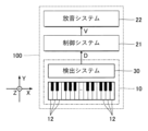
- FIG. 1 is a block diagram illustrating a configuration of a keyboard instrument according to a first embodiment.
- FIG. 2 is a side view illustrating the configuration of a keyboard unit.
- FIG. FIG. 2 is a block diagram illustrating a configuration of a detection system and a control system.
- FIG. 2 is a circuit diagram of a magnetic sensor.
- FIG. FIG. FIG. 2 is a block diagram illustrating a configuration of a drive circuit.
- FIG. 10 is a cross-sectional view taken along line XX in FIG. 9 .
- FIG. FIG. FIG. FIG. 11 is an enlarged side view of a base member and a second support member in a second embodiment.
- FIG. FIG. 11 is an explanatory diagram of a process for installing an adjustment member.
- FIG. 13 is a plan view of a driving substrate in a third embodiment.
- FIG. 1 is a block diagram illustrating a configuration of a keyboard instrument 100 according to a first embodiment of the present disclosure.
- the keyboard instrument 100 is an electronic instrument (specifically, an electronic piano) including a keyboard unit 10, a control system 21, and a sound emission system 22.
- the X axis is an axis that extends left-right (width direction) of the keyboard instrument 100.
- the Y axis is an axis that extends front-back (depth direction) of the keyboard instrument 100.
- the X-Y plane is parallel to the horizontal plane.
- the Z axis is an axis that extends up-down (vertical direction) of the keyboard instrument 100.
- the keyboard unit 10 comprises a number of keys 12 and a detection system 30.
- the keys 12 are performance operators that correspond to different pitches.
- the keys 12 include a number of white keys and a number of black keys, and are arranged along the X-axis.
- Each key 12 is configured as an elongated member that extends along the Y-axis, and is displaced in response to operation by the user (hereinafter referred to as "key operation"). Key operations by the user include, for example, pressing and releasing a key.
- the detection system 30 detects key operations by the user.
- the control system 21 generates an audio signal V according to the result of detection by the detection system 30.
- the audio signal V is a signal that represents the waveform of a musical sound according to the key operation.
- the control system 21 may be configured separately from the keyboard instrument 100.
- a general-purpose information processing device such as a smartphone, tablet terminal, or personal computer may be used as the control system 21.
- FIG. 2 is a side view illustrating the configuration of the keyboard unit 10.
- FIG. 2 illustrates the configuration focusing on one arbitrary key 12.
- Each key 12 of the keyboard unit 10 is supported by a balance pin 11.
- the front end of the key 12 is displaced vertically when the user presses and releases the key.
- a capstan 13 is installed at the rear end of the key 12.
- the keyboard unit 10 of the first embodiment is provided with a drive mechanism 14 for each of the multiple keys 12.
- the drive mechanism 14 is an action mechanism that operates in response to key operation by the user.
- the drive mechanism 14 is provided with a transmission mechanism 40 and a rotation mechanism 50.
- the transmission mechanism 40 is a mechanism that transmits the displacement of each key 12 linked to the key operation to the rotation mechanism 50.
- the transmission mechanism 40 includes a wippen 41, a wippen flange 42, a jack 43, a jack flange 44, and a back check 45.
- the wippen 41 is journaled on the wippen flange 42.
- the wippen 41 is provided with a jack flange 44 and a back check 45.
- Each element of the transmission mechanism 40 is formed, for example, from wood, a resin material, or a composite material.
- composite materials include composite materials such as FRP (Fiber Reinforced Plastics) or CFRP (Carbon Fiber Reinforced Plastics), which are a mixture of various fiber materials, and composite materials that are a mixture of multiple materials (such as wood, ceramics, metals, etc.).
- the pivot mechanism 50 comprises a butt 51, a butt flange 52, a catcher 53, a hammer shank 54, and a weight portion 55.
- the butt 51 is a structure journalled on the butt flange 52.
- the hammer shank 54 is a long cylindrical structure.
- the base end of the hammer shank 54 is fixed to the butt 51.
- the weight portion 55 is installed at the tip of the hammer shank 54.
- the weight portion 55 is a metal counterweight that allows the user to perceive an appropriate sense of weight when operating the key.
- the catcher 53 protrudes rearward from the butt 51.
- Each element of the pivot mechanism 50 other than the weight portion 55 is formed from, for example, wood, a resin material or a composite material.
- composite materials include composite materials such as FRP or CFRP, which are mixed with various fiber materials, and composite materials that are mixed with multiple materials (e.g., materials such as wood, ceramics, and metals).
- the drive mechanism 14 of the first embodiment is a mechanism for making the operation feeling perceived by the user when operating the keys closer to that of a natural keyboard instrument 100, and no actual string striking occurs.
- the butt 51 of the first embodiment is an example of a "movable member".
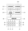
- FIG. 4 is a block diagram illustrating the configuration of the detection system 30 and the control system 21.
- the detection system 30 includes a plurality of magnetic sensors 31 corresponding to different drive mechanisms 14, and a drive circuit 35 that drives each of the plurality of magnetic sensors 31.
- the magnetic sensor 31 corresponding to each drive mechanism 14 is a sensor that detects the position of the hammer shank 54 of that drive mechanism 14.
- Each of the plurality of magnetic sensors 31 includes a signal generating unit 32 and a detected unit 33. That is, a pair of the signal generating unit 32 and the detected unit 33 is installed for each hammer shank 54.
- the detectable portion 33 is mounted on the drive mechanism 14. Specifically, the detectable portion 33 is mounted on the rotation mechanism 50. Therefore, the detectable portion 33 is displaced in conjunction with the key operation by the user. On the other hand, the signal generating portion 32 is not displaced during key operation. As can be understood from the above explanation, the distance between the detectable portion 33 and the signal generating portion 32 changes in conjunction with the key operation by the user.
- FIG. 5 is a circuit diagram illustrating the electrical configuration of any one of the magnetic sensors 31.
- the signal generating unit 32 is a resonant circuit including an input terminal 321, an output terminal 322, a resistive element 323, a driving coil 324, a capacitive element 325, and a capacitive element 326.
- One end of the resistive element 323 is connected to the input terminal 321, and the other end of the resistive element 323 is connected to one end of the capacitive element 325 and one end of the driving coil 324.
- the other end of the driving coil 324 is connected to the output terminal 322 and one end of the capacitive element 326.
- the other end of the capacitive element 325 and the other end of the capacitive element 326 are grounded (Gnd).
- each signal generating unit 32 is mounted on a drive board 36.
- FIG. 6 is a plan view of the drive board 36.
- the drive board 36 is a wiring board that extends in the direction of the X-axis across the multiple keys 12.
- Multiple signal generating units 32 corresponding to different keys 12 are mounted on the drive board 36.
- the multiple signal generating units 32 are arranged along the X-axis.
- the drive coils 324 of the signal generating units 32 are formed as a conductive pattern on the surface of the drive board 36. Note that in FIG. 6, elements other than the drive coils 324 in the signal generating units 32 are omitted from the illustration for convenience.
- the driving coil 324 of each signal generating unit 32 includes a first portion 324a and a second portion 324b.
- the first portion 324a and the second portion 324b are connected in series to form the driving coil 324.
- the first portion 324a and the second portion 324b are arranged in a direction perpendicular to the X-axis.
- the first portion 324a and the second portion 324b are formed in spiral shapes in opposite directions. Therefore, currents flow in the first portion 324a and the second portion 324b in opposite directions. In other words, the first portion 324a and the second portion 324b generate magnetic fields in opposite directions.
- the driving coil 324 may be formed of a multi-layer conductive pattern.
- the driving board 36 is an example of a "wiring board".
- the detected portion 33 is a resonant circuit including a capacitive element 331 and a moving coil 332. One end of the moving coil 332 and one end of the capacitive element 331 are connected to each other, and the other end of the moving coil 332 and the other end of the capacitive element 331 are connected to each other.
- the resonant frequency of the signal generating portion 32 and the resonant frequency of the detected portion 33 are set to be equal frequencies. However, the resonant frequency of the signal generating portion 32 and the resonant frequency of the detected portion 33 may be different.
- FIG. 7 is a plan view of the movable substrate 37.
- the movable substrate 37 is a wiring substrate that is individually installed for each key 12.
- the movable coil 332 of the detected part 33 is formed as a conductive pattern on the surface of the movable substrate 37. Note that in FIG. 7, elements other than the drive coil 324 in the signal generating part 32 are omitted from the illustration for convenience.
- the movable coil 332 of each detected part 33 includes a first part 332a and a second part 332b.
- the first part 332a and the second part 332b are connected in series to form the movable coil 332.
- the first part 332a and the second part 332b are arranged in a direction perpendicular to the X-axis.
- the first part 332a and the second part 332b are formed in spiral shapes in opposite directions. Therefore, currents flow in the first part 332a and the second part 332b in opposite directions. In other words, magnetic fields in opposite directions are generated in the first part 332a and the second part 332b.
- the drive coil 324 may be formed of a multi-layer conductive pattern.
- the driving coil 324 and the moving coil 332 face each other with a gap between them.
- the moving coil 332 is mounted on the hammer shank 54, so the distance between the driving coil 324 and the moving coil 332 changes according to the angle of the hammer shank 54.
- the driving circuit 35 in FIG. 4 generates a detection signal D according to the distance between the driving coil 324 and the moving coil 332.
- the driving coil 324 is an example of a "second coil”
- the moving coil 332 is an example of a "first coil.”
- FIG. 8 is a block diagram illustrating a specific configuration of the drive circuit 35.
- the drive circuit 35 includes a supply circuit 351 and an output circuit 352.
- the supply circuit 351 supplies a reference signal S to the input terminal 321 of each of the multiple signal generating units 32.
- the supply circuit 351 is a demultiplexer that supplies the reference signal S to each of the multiple signal generating units 32 in a time-division manner.
- the reference signal S is a signal whose level periodically changes. For example, a periodic signal of an arbitrary waveform such as a sine wave or a rectangular wave is used as the reference signal S.
- the frequency of the reference signal S is sufficiently shorter than the time length of the period during which the reference signal S is supplied to one signal generating unit 32.
- the frequency of the reference signal S is set to a frequency approximately equal to the resonant frequency of the signal generating unit 32 and the detected unit 33.
- the reference signal S is supplied to the drive coil 324 via the input terminal 321 and the resistance element 323.
- the supply of the reference signal S generates a magnetic field in the drive coil 324.
- An induced current is generated in the moving coil 332 of the detected part 33 due to electromagnetic induction caused by the magnetic field generated in the drive coil 324. That is, a magnetic field is generated in the moving coil 332 in a direction that offsets the change in the magnetic field of the drive coil 324.
- the magnetic field generated in the moving coil 332 changes according to the distance between the drive coil 324 and the moving coil 332.
- a detection signal d whose level fluctuates with an amplitude ⁇ according to the distance between the drive coil 324 and the moving coil 332 is output from the output terminal 322 of the signal generating unit 32.
- the detection signal d is a periodic signal whose level fluctuates at the same frequency as the reference signal S.
- the signal generating unit 32 generates a detection signal d according to the distance between the drive coil 324 and the moving coil 332.
- the output circuit 352 in FIG. 8 is a multiplexer that generates a detection signal D by arranging the detection signals d output sequentially from each of the multiple signal generating units 32 on the time axis. That is, the detection signal D is a signal whose level changes sequentially with an amplitude ⁇ according to the distance between the drive coil 324 and the moving coil 332. As described above, since the distance between the drive coil 324 and the moving coil 332 depends on the position of the hammer shank 54, the detection signal D is expressed as a signal according to the position of each of the multiple hammer shanks 54.
- the detection signal D generated by the output circuit 352 is supplied to the control system 21.
- the detection signal D may be rectified (half-wave or full-wave rectification) and smoothed before being supplied to the control system 21.
- the control system 21 in FIG. 4 generates an acoustic signal V in response to the detection signal D.
- the control system 21 is realized by a computer system including a control device 211, a storage device 212, an A/D converter 213, and a sound source device 214.
- the control system 21 may be realized by a single device, or may be realized by multiple devices configured separately from each other.
- the control device 211 is composed of one or more processors that control each element of the keyboard instrument 100.
- the control device 211 is composed of one or more types of processors, such as a CPU (Central Processing Unit), an SPU (Sound Processing Unit), a DSP (Digital Signal Processor), an FPGA (Field Programmable Gate Array), or an ASIC (Application Specific Integrated Circuit).
- a CPU Central Processing Unit
- SPU Sound Processing Unit
- DSP Digital Signal Processor
- FPGA Field Programmable Gate Array
- ASIC Application Specific Integrated Circuit
- the storage device 212 is a single or multiple memories that store the programs executed by the control device 211 and the data used by the control device 211.
- the storage device 212 is configured with a known recording medium, such as a magnetic recording medium or a semiconductor recording medium.
- the storage device 212 may also be configured with a combination of multiple types of recording media.
- a portable recording medium that can be attached to and detached from the keyboard instrument 100, or an external recording medium with which the keyboard instrument 100 can communicate (e.g., online storage) may be used as the storage device 212.
- the A/D converter 213 converts the detection signal D supplied from the drive circuit 35 from analog to digital.
- the control device 211 analyzes the position of each of the multiple hammer shanks 54 by analyzing the detection signal D after conversion by the A/D converter 213.
- the sound source device 214 generates an audio signal V representing the sound instructed by the control device 211.
- the control device 211 instructs the sound source device 214 to generate a musical tone according to the detection signal D.
- an audio signal V representing a musical tone according to the key operation by the user is generated.
- the control device 211 may realize the function of the sound source device 214 by executing a program stored in the storage device 212.
- the sound emission system 22 in FIG. 1 emits musical tones represented by the audio signal V.
- a single or multiple speakers, or headphones (earphones) worn on the user's head are used as the sound emission system 22.
- the sound emission system 22 configured separately from the keyboard instrument 100 may be connected to the keyboard instrument 100 by wire or wirelessly.
- a holding member 60 is installed on the rotating mechanism 50. Specifically, the holding member 60 is fixed to the butt 51 that constitutes the rotating mechanism 50.
- the holding member 60 is a structure that is integrally molded from, for example, a resin material (plastic) or a composite material.
- the holding member 60 is a holder for holding the movable substrate 37.
- the detected portion 33 is installed on the movable substrate 37. In other words, the movable coil 332 of the detected portion 33 is installed on the holding member 60.
- FIG. 9 is an enlarged view of the retaining member 60.
- the butt 51 and hammer shank 54 are shown in the side view located in the center of FIG. 9.
- FIG. 10 is a cross-sectional view taken along line X-X in FIG. 9.
- FIGS. 9 and 10 show a U-axis and a V-axis that are perpendicular to each other.
- the U-axis and the V-axis are axes in a plane (Y-Z plane) perpendicular to the X-axis.
- the V-axis is an axis parallel to the central axis of the hammer shank 54.
- the U-axis is an axis perpendicular to the V-axis and the X-axis.
- the bat 51 is a structure including an installation surface B and outer wall surfaces E (E1 to E4).
- the installation surface B is the upper surface facing the V-axis direction. In other words, the installation surface B is a flat surface parallel to the X-U plane.
- the hammer shank 54 is installed on the installation surface B. Specifically, the base end of the hammer shank 54 is fixed to the installation surface B. In other words, the hammer shank 54 protrudes from the installation surface B in the V-axis direction.
- the outer wall surface E is a side surface that intersects with the installation surface B. Specifically, the outer wall surface E includes side surface E1, side surface E2, front surface E3, and back surface E4, as illustrated in FIG. 9 and FIG. 10.
- the front surface E3 is a wall surface facing the positive direction of the U axis. In other words, the front surface E3 is a surface that faces the direction in which the butt 51 is displaced when the key is pressed. Specifically, the front surface E3 is continuous with the arc-shaped portion of the butt 51 on which the butt spring 56 is installed.
- the back surface E4 is a wall surface on the opposite side to the front surface E3. The aforementioned catcher 53 is installed on the back surface E4.
- the side surfaces E1 and E2 are wall surfaces that intersect with the installation surface B, the front surface E3, and the back surface E4. As illustrated in FIG. 10, the side surfaces E1 and E2 face in opposite directions between the front surface E3 and the back surface E4.
- the side surface E1 is an example of a "first side surface”
- the side surface E2 is an example of a "second side surface.”
- the holding member 60 is a structure in which a holding portion 61 and an attachment portion 62 are integrally molded.
- the holding portion 61 is a portion for holding the movable substrate 37.
- the holding portion 61 includes a substrate portion 611 and multiple edge portions 612 (612a, 612b, 612c).
- the substrate portion 611 is a long plate-like portion in the V-axis direction, and includes a first face F1 and a second face F2 located on opposite sides of each other.
- the first face F1 and the second face F2 are flat faces parallel to the X-V plane.
- the multiple edge portions 612 (612a, 612b, 612c) are protrusions that protrude from the first face F1 of the substrate portion 611 in the U-axis direction.
- the multiple edge portions 612 are installed at intervals from each other along the edge of the substrate portion 611.
- the movable substrate 37 is held by the holding portion 61 while being surrounded by multiple edges 612.
- edges 612a and 612b are protrusions that run along the short sides of the substrate portion 611. Edges 612a and 612b face the side surfaces that make up the short sides of the movable substrate 37.
- the multiple edges 612c are protrusions that run along the long sides of the substrate portion 611. Each edge 612c faces the side surfaces that make up the long sides of the movable substrate 37.
- the edge 612b is formed with a protruding portion 612d that protrudes toward the edge 612a so as to face the surface of the movable substrate 37.
- the movable substrate 37 is sandwiched between the substrate portion 611 and the protruding portion 612d near the end located in the negative direction of the V axis, and is fixed to the substrate portion 611 by a fastener Q such as a screw near the end located in the positive direction of the V axis.
- the mounting portion 62 is a portion for mounting the holding member 60 to the rotation mechanism 50 (specifically, the bat 51).
- the mounting portion 62 protrudes in the negative direction of the U-axis from the second surface F2 of the base portion 611.
- the mounting portion 62 has a side wall portion 621, a side wall portion 622, a top surface portion 623, an inclined portion 624, and a back surface portion 625.
- the side wall portion 621 and the side wall portion 622 are wall-like portions that protrude in the negative direction of the U-axis from the second surface F2 of the base portion 611.
- the side wall portion 621 and the side wall portion 622 face each other with a gap in the direction of the X-axis.
- the top surface portion 623 and the inclined portion 624 are portions that connect the upper edge of the side wall portion 621 and the upper edge of the side wall portion 622.
- the top surface portion 623 is a plate-like portion parallel to the X-U plane.
- a through hole 626 through which the hammer shank 54 passes is formed in the top surface portion 623.
- the top surface portion 623 is located between the inclined portion 624 and the base portion 611.
- the inclined portion 624 is a plate-like portion inclined with respect to the X-U plane.
- a rectangular opening 627 is formed in the inclined portion 624.
- the back surface portion 625 is a plate-like portion parallel to the X-V plane, and is continuous with the inclined portion 624.
- the inclined portion 624 may be omitted. In other words, a configuration in which the top surface portion 623 and the back surface portion 625 are continuous is also envisioned.
- the portion of the bat 51 located in the positive direction of the V axis is contained in a space surrounded by the base portion 611, the side wall portion 621, the side wall portion 622, and the back portion 625.
- the inner wall surface C1 of the side wall portion 621 contacts the side surface E1 of the bat 51.
- the inner wall surface C2 of the side wall portion 622 contacts the side surface E2 of the bat 51.
- the second surface F2 of the base portion 611 contacts the front surface E3 of the bat 51.
- the inner wall surface C4 of the back portion 625 contacts the back surface E4 of the bat 51.
- the second surface F2 of the base portion 611, the inner wall surface C1 of the side wall portion 621, the inner wall surface C2 of the side wall portion 622, and the inner wall surface C4 of the back portion 625 are collectively expressed as a contact surface C that contacts the outer wall surface E of the bat 51. That is, the holding member 60 of the first embodiment includes a contact surface C that contacts the outer wall surface E of the bat 51. As described above, the contact surface C includes a portion (second surface F2) that contacts the front surface E3 of the bat 51, a portion (inner wall surface C1) that contacts the side surface E1, and a portion (inner wall surface C2) that contacts the side surface E2.
- the inner wall surface C2 may not contact the outer wall surface E of the bat 51.
- the inner wall surface C4 of the back portion 625 may face the back surface E4 of the bat 51 with a gap therebetween.
- the holding member 60 includes a contact surface C that contacts the outer wall surface E of the butt 51.
- movement of the holding member 60 within the X-U plane perpendicular to the axis of the hammer shank 54 is restricted by contact between the contact surface C of the holding member 60 and the outer wall surface E of the butt 51. Therefore, compared to a configuration in which the holding member 60 does not include a contact surface C that contacts the outer wall surface E, the positional relationship between the moving coil 332 and the drive coil 324 can be set with high precision.
- the contact surface C of the holding member 60 includes a second surface F2 that contacts the front surface E3. Therefore, movement of the holding member 60 in the direction in which the bat 51 is displaced (e.g., the direction of the U axis) can be restricted by contact between the contact surface C (second surface F2) of the holding member 60 and the front surface E3 of the bat 51. Also, in the first embodiment, the contact surface C (inner wall surface C1 and inner wall surface C2) of the holding member 60 contacts the side surface E1 and side surface E2 of the bat 51.
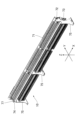
- FIG. 11 and 12 are perspective views of the keyboard unit 10. Note that while multiple drive mechanisms 14 are shown in FIG. 11, only one of the multiple drive mechanisms 14 is shown representatively in FIG. 12.
- the keyboard unit 10 includes a first support member 71, a second support member 72, a third support member 73, a fourth support member 74, and a number of base members 75. Note that the base members 75 are not shown in Figure 12.
- the first support member 71, the second support member 72, the third support member 73, and the fourth support member 74 are formed from a metal material such as stainless steel, and are long structures that are continuous across all the keys 12 of the keyboard unit 10.
- the first support member 71, the second support member 72, the third support member 73, and the fourth support member 74 extend along the X-axis so as to span the entire width of the keyboard unit 10.
- the multiple base members 75 are installed at intervals from each other in the direction of the X-axis.
- Each base member 75 is an action bracket that supports a first support member 71, a second support member 72, a third support member 73, and a fourth support member 74.
- the base members 75 are formed from a metal material such as stainless steel.
- Figure 13 is a perspective view of any one of the base members 75.
- the base member 75 is a structure in which a main body portion 750 and multiple mounting portions 751-754 are integrally formed.
- the base member 75 is manufactured by pressing a metal plate-like member.
- the main body portion 750 is a flat plate-like portion parallel to the Y-Z plane.
- Each of the multiple mounting portions 751-754 protrudes from the main body portion 750 in the direction of the X-axis.
- the first support member 71 is fixed to the mounting portion 751 by a fastener Q such as a screw.
- the second support member 72 is fixed to the mounting portion 752 by a fastener Q.
- the second support member 72 is fixed to the mounting portion 752 by a plurality of fasteners Q installed at intervals in the Z-axis direction.
- the third support member 73 is fixed to the mounting portion 753 by a fastener Q.
- the fourth support member 74 is fixed to the mounting portion 754 by a fastener Q.
- the first support member 71, the second support member 72, the third support member 73, and the fourth support member 74 are fixed to a common base member 75.
- the first support member 71 is a bracket that supports a regulating member 76.
- the regulating member 76 extends in the X-axis direction so as to cover all of the keys 12 of the keyboard unit 10.
- the regulating member 76 is formed from a cushioning material such as low-resilience rubber, a foam material, or a fiber material (e.g., felt). Note that multiple regulating members 76 may be arranged in the X-axis direction.
- the regulating member 76 is located on the rotational trajectory of the hammer shank 54. As the pivot mechanism 50 rotates, the hammer shank 54 collides with the regulating member 76, thereby limiting the displacement of the hammer shank 54. In other words, the regulating member 76 is a hammer stopper that regulates the displacement of the hammer shank 54. As can be understood from the above explanation, as the pivot mechanism 50 rotates, each detectable portion 33 reaches a position where the regulating member 76 collides with the hammer shank 54. In other words, the regulating member 76 determines the position of the detectable portion 33 during key operation. Specifically, the position of the detectable portion 33 when it is closest to the signal generating portion 32 is determined by the regulating member 76.
- the second support member 72 is a bracket that supports the drive board 36 and the control board 38.
- the drive board 36 is a wiring board on which a number of signal generating units 32 corresponding to different keys 12 are arranged in the X-axis direction.
- the control board 38 is a wiring board on which the drive circuit 35 of FIG. 4 is installed.
- the second support member 72 is a structure including a main body portion 721, a side wall portion 722, and a side wall portion 723.
- the main body portion 721 is a flat plate-shaped portion extending in the direction of the X-axis.
- the drive substrate 36 is fixed to the main body portion 721 by a fastener Q such as a screw.
- a spacer 39 is installed between the drive substrate 36 and the main body portion 721. Therefore, the drive substrate 36 and the main body portion 721 face each other with a predetermined gap between them.
- the entire area of the drive substrate 36 overlaps the main body portion 721 when viewed in the direction of the Y-axis.
- the side wall portion 722 protrudes in the positive direction of the Y axis from the upper edge of the main body portion 721.
- the side wall portion 723 protrudes in the positive direction of the Y axis from the lower edge of the main body portion 721. That is, the side wall portion 722 and the side wall portion 723 face each other with a gap between them in the direction of the Z axis.
- the control board 38 is fixed to the side wall portion 722 and the side wall portion 723.
- the main body portion 721 of the second support member 72 is located between the drive board 36 and the control board 38.
- the third support member 73 is a center rail that supports each drive mechanism 14. Specifically, the wippen flange 42 and the butt flange 52 of the drive mechanism 14 are fixed to the third support member 73. In other words, multiple drive mechanisms 14 corresponding to different keys 12 are fixed to a common third support member 73.
- the fourth support member 74 is a hammer rail that supports the buffer member 77.
- the buffer member 77 extends in the direction of the X-axis so as to cover all of the keys 12 of the keyboard unit 10.
- the buffer member 77 is made of a buffer material such as low-resilience rubber, a foam material, or a fiber material (e.g. felt).
- the first support member 71 that supports the regulating member 76 and the second support member 72 that supports the drive board 36 are fixed to a common base member 75. Therefore, compared to a configuration in which the first support member 71 and the second support member 72 are fixed to separate members, for example, the positional relationship between the drive coil 324 of the signal generating unit 32 and the movable coil 332 of the detected unit 33 can be set with high precision.
- the third support member 73 that supports the drive mechanism 14 is also fixed to the base member 75. Therefore, compared to a configuration in which the third support member 73 is fixed to a member separate from the base member 75, the effect of being able to set the positional relationship between the moving coil 332 and the drive coil 324 with high precision is particularly remarkable.
- Second embodiment A second embodiment will be described.
- elements having the same functions as those in the first embodiment will be denoted by the same reference numerals as those used in the description of the first embodiment, and detailed descriptions thereof will be omitted as appropriate.
- FIG. 14 is an enlarged side view of the vicinity of the mounting portion 752 of the base member 75 and the second support member 72. Note that in FIG. 14, the drive board 36 is omitted for convenience.
- an adjustment member 80 is interposed between the second support member 72 and the mounting portion 752.
- the adjustment member 80 is a spacer for adjusting the distance between the second support member 72 and the mounting portion 752.
- the adjustment member 80 is a plate-shaped member formed to a predetermined thickness.
- the position of the second support member 72 in the Y-axis direction is adjusted by changing the presence or absence and number of adjustment members 80 interposed between the second support member 72 and the mounting portion 752. Specifically, the position of the second support member 72 in the Y-axis direction changes in the positive direction of the Y-axis as the number of adjustment members 80 increases. Note that the distance between the second support member 72 and the base member 75 may be adjusted by selectively using one of multiple types of adjustment members 80 with different thicknesses.
- FIG. 15 is a plan view of the adjustment member 80.
- the adjustment member 80 is a plate-shaped member including a first arm portion 81, a second arm portion 82, a connecting portion 83, a first protrusion portion 84, and a second protrusion portion 85.
- the adjustment member 80 is formed, for example, by punching a plate-shaped member made of a resin material or a composite material.
- the first arm 81 and the second arm 82 are arranged side by side with a predetermined distance between them.
- the connecting portion 83 is a portion that connects the base end of the first arm 81 and the base end of the second arm 82. In other words, the first arm 81 and the second arm 82 extend linearly in the same direction from both ends of the connecting portion 83.
- the adjustment member 80 can also be expressed as a plate-shaped member formed into an oval ring or rectangular frame shape with an open longitudinal end.
- the first protrusion 84 protrudes from the tip of the first arm 81 toward the second arm 82.
- the second protrusion 85 protrudes from the tip of the second arm 82 toward the first arm 81.
- the distance between the first arm 81 and the second arm 82 is smaller at the tip where the first protrusion 84 and the second protrusion 85 are located compared to other parts.
- FIG. 16 is an explanatory diagram of the process of inserting the adjustment member 80 between the mounting portion 752 of the base member 75 and the second support member 72.
- FIG. 16 a plan view of the second support member 72 viewed from the positive direction of the Y axis is shown.
- the second support member 72 is positioned so as to overlap the mounting portion 752 of the base member 75.
- the second support member 72 is formed with an opening 725, an opening 726, a mounting hole 727, and a mounting hole 728.
- the openings 725 and 726 are, for example, rectangular through holes.
- the mounting holes 727 and 728 are circular through holes into which fasteners Q are inserted.
- the openings 725 and the mounting holes 727 are continuous with each other.
- the mounting portion 752 of the base member 75 is formed with a screw hole 755 and a screw hole 756.
- the mounting hole 727 overlaps with the screw hole 755, and the mounting hole 728 overlaps with the screw hole 756.
- fastener Qa and fastener Qb are temporarily fastened. Specifically, fastener Qa passes through mounting hole 727 and is inserted into screw hole 755, and fastener Qb passes through mounting hole 728 and is inserted into screw hole 756.
- fastener Qa and fastener Qb are not completely fastened. Therefore, the distance between the second support member 72 and the mounting portion 752 can be changed. For example, the distance between the second support member 72 and the mounting portion 752 can be expanded to the extent that multiple adjustment members 80 can be inserted.
- adjustment member 80 is inserted into the gap between second support member 72 and mounting portion 752. Specifically, adjustment member 80 is inserted from below into the gap between second support member 72 and mounting portion 752 with first protrusion 84 and second protrusion 85 positioned upward.
- the distance between the first protrusion 84 and the second protrusion 85 is less than the outer diameter of the threaded portion of the fastener Q (Qa, Qb) located between the second support member 72 and the mounting portion 752. Therefore, the distance between the first protrusion 84 and the second protrusion 85 is temporarily expanded in the process of the fastener Q passing between the first protrusion 84 and the second protrusion 85. As illustrated in FIG. 16, the adjustment member 80 is moved upward until the fastener Qa passes between the first protrusion 84 and the second protrusion 85.
- step P3 multiple adjustment members 80 may be interposed between the second support member 72 and the mounting portion 752.
- openings 725 and 726 are formed so as to overlap a portion of adjustment member 80 in the held state. Specifically, opening 725 is formed so as to expose first protrusion 84 and second protrusion 85 of adjustment member 80 in the held state. Therefore, the person in charge of keyboard instrument 100 (e.g., the manufacturer or adjuster) can visually check through opening 725 whether fastener Qa has passed between first protrusion 84 and second protrusion 85. Also, adjustment member 80 can be moved by inserting a tool or finger into opening 725 and touching adjustment member 80.
- an opening 726 is formed so that a portion of the second arm 82 of the adjustment member 80 in the held state is exposed. Therefore, the manager of the keyboard instrument 100 can visually check the state of the second arm 82 (e.g., whether the angle is appropriate) through the opening 726.
- the adjustment member 80 can be moved by inserting a tool or a finger into the opening 726 and touching the adjustment member 80.
- the fasteners Qa and Qb are completely fastened. That is, the second support member 72 is fixed to the mounting portion 752 of the base member 75 by a plurality of fasteners Q (Qa, Qb) installed at intervals from each other.
- the adjustment member 80 is interposed between the support member and the base member 75 (mounting portion 752) with the fasteners Qa and Qb positioned between the first arm portion 81 and the second arm portion 82.
- an adjustment member 80 is interposed between the second support member 72 and the base member 75.
- the adjustment member 80 adjusts the distance between the second support member 72 and the base member 75, and as a result, the position of the drive coil 324 in the Y-axis direction is adjusted. Therefore, the positional relationship between the drive coil 324 and the movable coil 332 can be adjusted according to the plate thickness or number of adjustment members 80.
- the adjustment member 80 can be easily attached and detached in a state in which the second support member 72 and the base member 75 are mutually held by the multiple fasteners Q.
- the adjustment member 80 is attached by moving the adjustment member 80 so that the multiple fasteners Q pass between the first arm portion 81 and the second arm portion 82 in sequence, and the adjustment member 80 is removed by moving the adjustment member 80 so that the multiple fasteners Q are sequentially removed from between the first arm portion 81 and the second arm portion 82.
- the angle of the adjustment member 80 is guided so that the longitudinal direction of the adjustment member 80 is aligned with the direction of the arrangement of the multiple fasteners Q. Therefore, the possibility that the adjustment member 80 will be installed at an angle deviating from the target angle can be reduced.
- a first protrusion 84 and a second protrusion 85 that face each other are installed on the adjustment member 80.
- the first protrusion 84 and the second protrusion 85 are hooked onto the fastener Q, reducing the possibility that the adjustment member 80 will fall off the fastener Q. In other words, even if the adjustment member 80 is not held from the outside, the adjustment member 80 will remain held by the fastener Q. This makes it easy to attach and detach the adjustment member 80.
- the adjustment member 80 can be viewed or operated through the opening 725 or opening 726 from the opposite side of the second support member 72 to the base member 75. Therefore, the adjustment member 80 can be attached and detached more easily than in a configuration in which the opening 725 or opening 726 is not formed in the second support member 72.
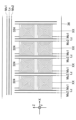
- Fig. 17 is a schematic diagram of a drive substrate 36 in a third embodiment.
- a set of a reference line Lz and an allowable line Mz1 and an allowable line Mz2 is formed for each drive coil 324 on the surface of the drive substrate 36.
- the reference line Lz and each allowable line Mz (Mz1, Mz2) are formed by white paint on the green surface of the drive substrate 36.
- the reference line Lz and each allowable line Mz are straight lines extending in the direction of the Z axis.
- the reference line Lz is a solid line that runs along the long side of the drive coil 324.
- the tolerance line Mz1 is a dashed line that is spaced a predetermined distance from the reference line Lz in the positive direction of the X-axis.
- the tolerance line Mz2 is a dashed line that is spaced a predetermined distance from the reference line Lz in the negative direction of the X-axis.
- the reference line Lz is located between the tolerance lines Mz1 and Mz2, which extend parallel to each other.
- a reference line Lx and tolerance lines Mx1 and Mx2 are formed on the surface of the drive substrate 36.
- the reference line Lx and each tolerance line Mx (Mx1, Mx2) are formed on the green surface of the drive substrate 36 using white paint.
- the reference line Lx and each tolerance line Mx are straight lines extending in the direction of the X-axis.
- the reference line Lx is a solid line that runs along the short side of each drive coil 324 and is continuous across multiple drive coils 324.
- the tolerance line Mx1 is a dashed line that is spaced a predetermined distance from the reference line Lx in the positive direction of the Z axis.
- the tolerance line Mx2 is a wire that is spaced a predetermined distance from the reference line Lx in the negative direction of the Z axis.
- the reference line Lx is located between the tolerance lines Mx1 and Mx2, which extend parallel to each other.
- Each reference line (Lz, Lx) and each tolerance line (Mz1, Mz2, Mx1, Mx2) is used to adjust the position of the drive substrate 36 relative to each drive mechanism 14.
- each movable substrate 37 faces the drive substrate 36.
- the position of the drive substrate 36 relative to each movable substrate 37 is adjusted so that the drive coil 324 of the drive substrate 36 and the movable coil 332 of the movable substrate 37 face each other.
- the position of the drive substrate 36 in the X-axis direction is adjusted so that the long side of each movable substrate 37 is located between the tolerance lines Mz1 and Mz2.
- the position of the drive substrate 36 in the X-axis direction is adjusted so that the long side of each movable substrate 37 overlaps with the reference line Lz.
- the reference line Lz represents the ideal position of the long side of the movable substrate 37.
- the range between the tolerance lines Mz1 and Mz2 represents the allowable error range for the position of the long side of the movable substrate 37.
- the position of the drive substrate 36 in the direction of the Z axis is adjusted so that the short side of each movable substrate 37 is located between the tolerance line Mx1 and the tolerance line Mx2.
- the position of the drive substrate 36 in the direction of the Z axis is adjusted so that the short side of each movable substrate 37 overlaps with the reference line Lx.
- the reference line Lx means the ideal position of the short side of the movable substrate 37.
- the range between the tolerance line Mx1 and the tolerance line Mx2 means the allowable error range for the position of the short side of the movable substrate 37.
- the third embodiment also achieves the same effects as the first embodiment. Furthermore, in the third embodiment, the positional relationship between each drive coil 324 and each movable coil 332 can be adjusted with high precision by utilizing each reference line (Lz, Lx) and each tolerance line (Mz1, Mz2, Mx1, Mx2) formed on the surface of the drive substrate 36.
- the configuration of the second embodiment is also applicable to the third embodiment.
- each of the configurations A to C can be established independently of the other. Therefore, each of the configurations A to C does not require the other configurations.
- a configuration in which the holding member 60 and the bat 51 do not come into contact is also assumed.
- a configuration in which the configuration B is adopted a configuration in which the first support member 71 and the second support member 72 are fixed to different members is also assumed.
- a configuration in which the configuration C is adopted a configuration in which the first support member 71 and the second support member 72 are fixed to different members, or a configuration in which the holding member 60 and the bat 51 do not come into contact is also assumed.
- the rotation of the rotating mechanism 50 may be detected by a sensor other than the magnetic sensor 31.
- a sensor such as an optical sensor or a mechanical sensor is used to detect the rotation of the rotating mechanism 50.
- the holding member 60 and the butt 51 are shown as separate bodies, but the holding member 60 may be formed integrally with the butt 51.
- an integral molded product including the holding member 60 and the butt 51 may be formed by injection molding of, for example, a resin material or a composite material.
- the hammer shank 54 may also be formed integrally with the holding member 60 and the butt 51.
- the hammer shank 54 which is configured separately from the butt 51, is fixed to the butt 51, but the hammer shank 54 and butt 51 may be formed as one piece.
- an integrated molded product including the hammer shank 54 and butt 51 is molded by injection molding of, for example, a resin material or a composite material.
- the rod-shaped hammer shank 54 before the weight portion 55 is installed is inserted into the through hole 626 of the holding member 60, whereby the holding member 60 is installed on the butt 51, and the weight portion 55 is installed on the hammer shank 54 after the holding member 60 is installed.
- the first portion 324a and the second portion 324b of the drive coil 324 are formed into a spiral shape in opposite directions, but the shape of the drive coil 324 is not limited to the above examples.
- the first portion 324a and the second portion 324b may be formed into a spiral shape in the same direction.
- the drive coil 324 may be composed of a single spiral portion. In other words, one of the first portion 324a and the second portion 324b may be omitted.
- the moving coil 332 is not limited to a shape including the first portion 332a and the second portion 332b.
- the first portion 332a and the second portion 332b may be formed in a spiral shape in the same direction.
- the moving coil 332 may also be composed of a single spiral portion. In other words, one of the first portion 332a and the second portion 332b may be omitted.
- an electronic musical instrument in which the sound source device 214 generates the audio signal V has been exemplified, but the above embodiments can also be applied to a natural keyboard instrument in which a sound source such as a string generates musical tones.
- a natural keyboard instrument the weight portion 55 in each of the above embodiments is replaced with a hammer for striking the strings.
- the above embodiments can also be applied to a keyboard instrument equipped with a string-striking mechanism, such as an automatic piano or a silent piano.
- the detection system 30 is used to detect the displacement of a movable member such as the key 12 or the hammer shank 54 (or the hammer).
- an upright type drive mechanism 14 (action mechanism) is exemplified, but each of the above embodiments can be applied to a keyboard instrument equipped with a grand piano type drive mechanism. Furthermore, the type of keyboard instrument to which this disclosure applies is not limited to the piano. For example, each of the above embodiments can be applied to various keyboard instruments such as a celesta or glockenspiel.
- nth (n is a natural number) in this application is used only as a formal and convenient label to distinguish each element in the description and does not have any substantive meaning. Therefore, there is no room for restrictive interpretation of the position of each element or the order of manufacture, etc., based on the term "nth.”
- Supplementary Note A A1-A2
- Supplementary Note B B1-B3
- Supplementary Note C C1-C4
- a keyboard instrument includes a drive mechanism including a hammer shank that is displaced in response to key operation, a regulating member that the hammer shank collides with due to displacement, a first support member that supports the regulating member, a first coil installed in the drive mechanism, a signal generating unit including a second coil that generates a magnetic field, a wiring board on which the signal generating unit is installed that generates a detection signal according to the distance between the first coil and the second coil, a second support member that supports the wiring board, and a base member, and the first support member and the second support member are fixed to the base member.
- the first support member that supports the regulating member and the second support member that supports the wiring board are fixed to a common base member. Therefore, for example, compared to a form in which the first support member and the second support part are fixed to separate members, the positional relationship between the first coil and the second coil can be set with high precision.
- a specific example of A1 (Aspect A2) further includes a third support member that supports the drive mechanism, and the third support member is fixed to the base member.
- the third support member that supports the drive mechanism is also fixed to the base member. Therefore, compared to a configuration in which the third support member is fixed to a member separate from the base member, the effect of being able to set the positional relationship between the first coil and the second coil with high precision is particularly remarkable.
- a keyboard instrument includes a drive mechanism including a movable member displaced in response to key operation and a hammer shank attached to the movable member, a holding member attached to the movable member, a first coil attached to the holding member, and a second coil that generates a magnetic field, and a signal generating unit that generates a detection signal according to the distance between the first coil and the second coil, the movable member including a mounting surface from which the hammer shank protrudes and an outer wall surface that intersects with the mounting surface, and the holding member including a contact surface that contacts the outer wall surface.
- the holding member includes a contact surface that contacts the outer wall surface of the movable member. That is, the movement of the holding member in a plane perpendicular to the axis of the hammer shank is restricted by the contact surface of the holding member and the outer wall surface of the movable member. Therefore, the positional relationship between the first coil and the second coil can be set with high precision, compared to an aspect in which the holding member does not include a contact surface that contacts the outer wall surface.
- the outer wall surface includes a front surface facing the direction in which the movable member is displaced by the key operation, and the contact surface includes a portion that contacts the front surface.
- the outer wall surface includes a first side and a second side that intersect with the installation surface and the front surface, the first side and the second side face in opposite directions, and the contact surface includes a portion that contacts the first side and a portion that contacts the second side.
- the contact surface of the retaining member contacts the first side and the second side of the movable member. Therefore, movement of the retaining member in the direction in which the first side or the second side faces (the horizontal direction in which the multiple keys are arranged) can be restricted by contact between the first side and the second side and the contact surface of the retaining member.
- a keyboard instrument includes a driving mechanism including a hammer shank that is displaced in response to key operation, a first coil installed in the driving mechanism, a signal generating unit including a second coil that generates a magnetic field, a wiring board on which the signal generating unit is installed, the signal generating unit generating a detection signal according to the distance between the first coil and the second coil, a support member that supports the wiring board, a base member to which the support member is fixed, and an adjustment member that is interposed between the support member and the base member.
- the adjustment member is interposed between the support member that supports the wiring board and the base member to which the support member is fixed. The adjustment member adjusts the distance between the support member and the base member, and as a result, the position of the second coil is adjusted. Therefore, the positional relationship between the first coil and the second coil can be adjusted according to the plate thickness or number of the adjustment members.
- the adjustment member is a plate-like member including a first arm and a second arm arranged in parallel with a gap between them, and a connecting portion connecting the base end of the first arm and the base end of the second arm, and the support member is fixed to the base member by a plurality of fasteners arranged at a gap between them, the plurality of fasteners being located between the first arm and the second arm.
- the adjustment member can be easily attached and detached while the support member and the base member are held together by the plurality of fasteners.
- the adjustment member is guided so that the direction in which the first arm and the second arm extend is along the direction of the arrangement of the plurality of fasteners. Therefore, the possibility of the adjustment member being set at an angle that deviates from the target angle can be reduced.
- the adjustment member includes a first protrusion protruding from the tip of the first arm toward the second arm, and a second protrusion protruding from the tip of the second arm toward the first arm.
- the first protrusion and second protrusion which face each other, are attached to the adjustment member. The first protrusion and the second protrusion are caught on the fastener, reducing the possibility of the adjustment member falling off the fastener. In other words, even if the adjustment member is not held from the outside, the adjustment member is maintained in a state held by the fastener. This makes it easy to attach and detach the adjustment member.
- the support member has an opening that overlaps with a portion of the adjustment member.
- the adjustment member can be viewed or operated through the opening from the opposite side of the support member to the base member. Therefore, the adjustment member can be easily attached and detached compared to a configuration in which no opening is formed in the support member.
Landscapes
- Physics & Mathematics (AREA)
- Engineering & Computer Science (AREA)
- Acoustics & Sound (AREA)
- Multimedia (AREA)
- Electrophonic Musical Instruments (AREA)
Priority Applications (2)
| Application Number | Priority Date | Filing Date | Title |
|---|---|---|---|
| JP2024574835A JPWO2024162169A1 (https=) | 2023-02-01 | 2024-01-25 | |
| US19/287,194 US20250363968A1 (en) | 2023-02-01 | 2025-07-31 | Keyboard musical instrument |
Applications Claiming Priority (2)
| Application Number | Priority Date | Filing Date | Title |
|---|---|---|---|
| JP2023-014150 | 2023-02-01 | ||
| JP2023014150 | 2023-02-01 |
Related Child Applications (1)
| Application Number | Title | Priority Date | Filing Date |
|---|---|---|---|
| US19/287,194 Continuation US20250363968A1 (en) | 2023-02-01 | 2025-07-31 | Keyboard musical instrument |
Publications (1)
| Publication Number | Publication Date |
|---|---|
| WO2024162169A1 true WO2024162169A1 (ja) | 2024-08-08 |
Family
ID=92146639
Family Applications (1)
| Application Number | Title | Priority Date | Filing Date |
|---|---|---|---|
| PCT/JP2024/002195 Ceased WO2024162169A1 (ja) | 2023-02-01 | 2024-01-25 | 鍵盤楽器 |
Country Status (3)
| Country | Link |
|---|---|
| US (1) | US20250363968A1 (https=) |
| JP (1) | JPWO2024162169A1 (https=) |
| WO (1) | WO2024162169A1 (https=) |
Citations (6)
| Publication number | Priority date | Publication date | Assignee | Title |
|---|---|---|---|---|
| JPH06505569A (ja) * | 1991-02-06 | 1994-06-23 | ミラー、ジェイムズ、エム. | 自動演奏型楽器用記録システム |
| JPH08292766A (ja) * | 1995-04-19 | 1996-11-05 | Yamaha Corp | 鍵盤楽器 |
| JP2014021233A (ja) * | 2012-07-17 | 2014-02-03 | Yamaha Corp | 鍵盤楽器 |
| JP2018022179A (ja) * | 2017-09-27 | 2018-02-08 | ヤマハ株式会社 | サポートアセンブリおよび鍵盤装置 |
| WO2021100475A1 (ja) * | 2019-11-20 | 2021-05-27 | ヤマハ株式会社 | 演奏操作装置 |
| WO2021193389A1 (ja) * | 2020-03-26 | 2021-09-30 | ヤマハ株式会社 | 変位センサーおよび電子楽器 |
Family Cites Families (2)
| Publication number | Priority date | Publication date | Assignee | Title |
|---|---|---|---|---|
| JP3413931B2 (ja) * | 1994-02-22 | 2003-06-09 | ヤマハ株式会社 | 竪型鍵盤楽器 |
| JP4855611B2 (ja) * | 2001-09-12 | 2012-01-18 | 株式会社河合楽器製作所 | ピアノの止音装置 |
-
2024
- 2024-01-25 JP JP2024574835A patent/JPWO2024162169A1/ja active Pending
- 2024-01-25 WO PCT/JP2024/002195 patent/WO2024162169A1/ja not_active Ceased
-
2025
- 2025-07-31 US US19/287,194 patent/US20250363968A1/en active Pending
Patent Citations (6)
| Publication number | Priority date | Publication date | Assignee | Title |
|---|---|---|---|---|
| JPH06505569A (ja) * | 1991-02-06 | 1994-06-23 | ミラー、ジェイムズ、エム. | 自動演奏型楽器用記録システム |
| JPH08292766A (ja) * | 1995-04-19 | 1996-11-05 | Yamaha Corp | 鍵盤楽器 |
| JP2014021233A (ja) * | 2012-07-17 | 2014-02-03 | Yamaha Corp | 鍵盤楽器 |
| JP2018022179A (ja) * | 2017-09-27 | 2018-02-08 | ヤマハ株式会社 | サポートアセンブリおよび鍵盤装置 |
| WO2021100475A1 (ja) * | 2019-11-20 | 2021-05-27 | ヤマハ株式会社 | 演奏操作装置 |
| WO2021193389A1 (ja) * | 2020-03-26 | 2021-09-30 | ヤマハ株式会社 | 変位センサーおよび電子楽器 |
Also Published As
| Publication number | Publication date |
|---|---|
| US20250363968A1 (en) | 2025-11-27 |
| JPWO2024162169A1 (https=) | 2024-08-08 |
Similar Documents
| Publication | Publication Date | Title |
|---|---|---|
| US5115705A (en) | Modular electronic keyboard with improved signal generation | |
| US7060883B2 (en) | Compact keyboard apparatus with accurate detection of key pressing speed | |
| EP2884486B1 (en) | Installation structure for acoustic transducer | |
| US9532124B2 (en) | Installation structure for acoustic transducer | |
| US9373314B2 (en) | Installation structure for acoustic transducer | |
| US6002078A (en) | Keyboard assembly for electronic musical instrument | |
| JP2012014003A (ja) | 打楽器用打撃検出装置 | |
| US20220277719A1 (en) | Musical instrument playing apparatus and musical keyboard instrument | |
| US9269335B2 (en) | Installation structure for acoustic transducer | |
| US11183162B2 (en) | Keyboard apparatus | |
| CN107438880A (zh) | 电子打击乐器 | |
| CN109891492B (zh) | 键盘装置 | |
| US10885884B2 (en) | Pivot member and keyboard apparatus | |
| US20240078984A1 (en) | Detection system for musical instrument and musical instrument | |
| US5955690A (en) | Keyboard assembly for electronic musical instrument | |
| WO2024162169A1 (ja) | 鍵盤楽器 | |
| JP2021149029A (ja) | 鍵盤装置の鍵の支持構造 | |
| JP3233054B2 (ja) | 鍵盤装置 | |
| JP3846555B2 (ja) | 電子楽器用鍵盤装置 | |
| CN116486767A (zh) | 键盘单元 | |
| US20240046905A1 (en) | Keyboard apparatus | |
| US20230186885A1 (en) | Electronic stringed instrument, musical sound control method and recording medium | |
| US20250210019A1 (en) | Keyboard device and method for detecting key-pressing information | |
| CN116490919B (zh) | 键盘装置 | |
| JP3700622B2 (ja) | バネ機構 |
Legal Events
| Date | Code | Title | Description |
|---|---|---|---|
| 121 | Ep: the epo has been informed by wipo that ep was designated in this application |
Ref document number: 24750118 Country of ref document: EP Kind code of ref document: A1 |
|
| WWE | Wipo information: entry into national phase |
Ref document number: 2024574835 Country of ref document: JP |
|
| NENP | Non-entry into the national phase |
Ref country code: DE |
|
| 122 | Ep: pct application non-entry in european phase |
Ref document number: 24750118 Country of ref document: EP Kind code of ref document: A1 |