WO2024161960A1 - 円筒形の非水電解質二次電池 - Google Patents
円筒形の非水電解質二次電池 Download PDFInfo
- Publication number
- WO2024161960A1 WO2024161960A1 PCT/JP2024/000722 JP2024000722W WO2024161960A1 WO 2024161960 A1 WO2024161960 A1 WO 2024161960A1 JP 2024000722 W JP2024000722 W JP 2024000722W WO 2024161960 A1 WO2024161960 A1 WO 2024161960A1
- Authority
- WO
- WIPO (PCT)
- Prior art keywords
- negative electrode
- tab
- reinforcing plate
- winding
- secondary battery
- Prior art date
- Legal status (The legal status is an assumption and is not a legal conclusion. Google has not performed a legal analysis and makes no representation as to the accuracy of the status listed.)
- Ceased
Links
Images






Classifications
-
- H—ELECTRICITY
- H01—ELECTRIC ELEMENTS
- H01M—PROCESSES OR MEANS, e.g. BATTERIES, FOR THE DIRECT CONVERSION OF CHEMICAL ENERGY INTO ELECTRICAL ENERGY
- H01M50/00—Constructional details or processes of manufacture of the non-active parts of electrochemical cells other than fuel cells, e.g. hybrid cells
- H01M50/10—Primary casings; Jackets or wrappings
- H01M50/102—Primary casings; Jackets or wrappings characterised by their shape or physical structure
- H01M50/107—Primary casings; Jackets or wrappings characterised by their shape or physical structure having curved cross-section, e.g. round or elliptic
-
- H—ELECTRICITY
- H01—ELECTRIC ELEMENTS
- H01M—PROCESSES OR MEANS, e.g. BATTERIES, FOR THE DIRECT CONVERSION OF CHEMICAL ENERGY INTO ELECTRICAL ENERGY
- H01M10/00—Secondary cells; Manufacture thereof
- H01M10/05—Accumulators with non-aqueous electrolyte
- H01M10/058—Construction or manufacture
- H01M10/0587—Construction or manufacture of accumulators having only wound construction elements, i.e. wound positive electrodes, wound negative electrodes and wound separators
-
- H—ELECTRICITY
- H01—ELECTRIC ELEMENTS
- H01M—PROCESSES OR MEANS, e.g. BATTERIES, FOR THE DIRECT CONVERSION OF CHEMICAL ENERGY INTO ELECTRICAL ENERGY
- H01M50/00—Constructional details or processes of manufacture of the non-active parts of electrochemical cells other than fuel cells, e.g. hybrid cells
- H01M50/50—Current conducting connections for cells or batteries
- H01M50/531—Electrode connections inside a battery casing
- H01M50/533—Electrode connections inside a battery casing characterised by the shape of the leads or tabs
-
- H—ELECTRICITY
- H01—ELECTRIC ELEMENTS
- H01M—PROCESSES OR MEANS, e.g. BATTERIES, FOR THE DIRECT CONVERSION OF CHEMICAL ENERGY INTO ELECTRICAL ENERGY
- H01M50/00—Constructional details or processes of manufacture of the non-active parts of electrochemical cells other than fuel cells, e.g. hybrid cells
- H01M50/50—Current conducting connections for cells or batteries
- H01M50/531—Electrode connections inside a battery casing
- H01M50/534—Electrode connections inside a battery casing characterised by the material of the leads or tabs
-
- H—ELECTRICITY
- H01—ELECTRIC ELEMENTS
- H01M—PROCESSES OR MEANS, e.g. BATTERIES, FOR THE DIRECT CONVERSION OF CHEMICAL ENERGY INTO ELECTRICAL ENERGY
- H01M50/00—Constructional details or processes of manufacture of the non-active parts of electrochemical cells other than fuel cells, e.g. hybrid cells
- H01M50/50—Current conducting connections for cells or batteries
- H01M50/531—Electrode connections inside a battery casing
- H01M50/538—Connection of several leads or tabs of wound or folded electrode stacks
-
- Y—GENERAL TAGGING OF NEW TECHNOLOGICAL DEVELOPMENTS; GENERAL TAGGING OF CROSS-SECTIONAL TECHNOLOGIES SPANNING OVER SEVERAL SECTIONS OF THE IPC; TECHNICAL SUBJECTS COVERED BY FORMER USPC CROSS-REFERENCE ART COLLECTIONS [XRACs] AND DIGESTS
- Y02—TECHNOLOGIES OR APPLICATIONS FOR MITIGATION OR ADAPTATION AGAINST CLIMATE CHANGE
- Y02E—REDUCTION OF GREENHOUSE GAS [GHG] EMISSIONS, RELATED TO ENERGY GENERATION, TRANSMISSION OR DISTRIBUTION
- Y02E60/00—Enabling technologies; Technologies with a potential or indirect contribution to GHG emissions mitigation
- Y02E60/10—Energy storage using batteries
-
- Y—GENERAL TAGGING OF NEW TECHNOLOGICAL DEVELOPMENTS; GENERAL TAGGING OF CROSS-SECTIONAL TECHNOLOGIES SPANNING OVER SEVERAL SECTIONS OF THE IPC; TECHNICAL SUBJECTS COVERED BY FORMER USPC CROSS-REFERENCE ART COLLECTIONS [XRACs] AND DIGESTS
- Y02—TECHNOLOGIES OR APPLICATIONS FOR MITIGATION OR ADAPTATION AGAINST CLIMATE CHANGE
- Y02P—CLIMATE CHANGE MITIGATION TECHNOLOGIES IN THE PRODUCTION OR PROCESSING OF GOODS
- Y02P70/00—Climate change mitigation technologies in the production process for final industrial or consumer products
- Y02P70/50—Manufacturing or production processes characterised by the final manufactured product
Definitions
- This disclosure relates to a cylindrical non-aqueous electrolyte secondary battery.
- Patent Document 1 A conventional cylindrical non-aqueous electrolyte secondary battery is described in Patent Document 1.
- the negative electrode provided with the negative electrode mixture layer has a non-facing portion that does not face the positive electrode at the start of winding the electrode body, and this non-facing portion exists for two or more revolutions.
- this non-aqueous electrolyte secondary battery suppresses deformation at the start of winding the electrode body.
- cylindrical non-aqueous electrolyte secondary batteries if the hollow part of the electrode body becomes blocked due to separator melting or the like during abnormal heat generation, it may become impossible to secure a sufficient exhaust path to the outside via the hollow part, and high-temperature gas may not be able to be smoothly exhausted to the outside. Therefore, there is a need for a cylindrical non-aqueous electrolyte secondary battery that can prevent the hollow part of the electrode body from becoming blocked even when abnormal heat is generated, and can smoothly exhaust gas to the outside via the hollow part.
- a configuration can be considered in which a non-facing portion is formed at the winding start end of the negative electrode, wound so as not to face the positive electrode, and the negative electrode tab is joined to this non-facing portion while being wound 0.75 turns or more, thereby preventing blockage of the hollow portion of the electrode body in the event of abnormal heat generation.
- both ends of the negative electrode tab in the winding direction become angular, which may increase the diameter of the wound electrode body and make it difficult to insert it into the outer can.
- the battery is repeatedly charged and discharged, there is a risk that the electrode plate will buckle, starting from the angular parts of the negative electrode tab.
- the objective of this disclosure is to provide a cylindrical nonaqueous electrolyte secondary battery that can smoothly exhaust gas to the outside through the hollow portion of the electrode body even if abnormal heat is generated, and that can prevent both ends of the negative electrode tab from becoming angular in the winding direction.
- the cylindrical nonaqueous electrolyte secondary battery according to the present disclosure is a cylindrical nonaqueous electrolyte secondary battery comprising an electrode assembly in which a long positive electrode and a long negative electrode are wound with a separator interposed therebetween, a nonaqueous electrolyte, and an exterior can housing the electrode assembly and the nonaqueous electrolyte, the negative electrode including a non-facing portion wound from a portion facing the inside of the winding of the starting end of the winding direction of the positive electrode to the winding start side in a state not facing the positive electrode, and a tab reinforcing plate group joined to the non-facing portion, the tab reinforcing plate group including a negative electrode tab and at least one reinforcing plate, the winding start end of the tab reinforcing plate group being the starting point of the winding revolution, the negative electrode tab and at least one reinforcing plate being arranged in a predetermined order from the starting point toward the winding end side so as to be lined up for a total of 0.75 revolution
- the cylindrical nonaqueous electrolyte secondary battery disclosed herein allows gas to be smoothly exhausted to the outside through the hollow portion of the electrode body even if abnormal heat is generated, and prevents both ends of the negative electrode tab from becoming angular in the winding direction.
- FIG. 1 is an axial cross-sectional view of a cylindrical nonaqueous electrolyte secondary battery according to an embodiment of the present disclosure.
- FIG. 2 is a perspective view of an electrode assembly of the nonaqueous electrolyte secondary battery.
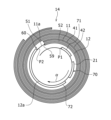
- 4 is a plan view showing the winding structure at the winding start side of the electrode body.
- FIG. FIG. 2 is a diagram showing the outer surface of a rolled long negative electrode. This is a cross-sectional view taken along line AA in FIG. 1 is a schematic diagram showing a state in which a hollow portion of an electrode body is surrounded by a group of tab reinforcing plates.
- FIG. 6 is a view corresponding to FIG.
- FIG. 5 is a view corresponding to FIG. 4 of a negative electrode constituting a cylindrical nonaqueous electrolyte secondary battery according to another example of the embodiment.
- FIG. 6 is a view corresponding to FIG. 5 of a negative electrode constituting a cylindrical nonaqueous electrolyte secondary battery according to another example of the embodiment.
- the sealing body 17 side in the axial direction (height direction) of the cylindrical nonaqueous electrolyte secondary battery 10 is referred to as "upper”
- the bottom 68 side of the exterior can 16 in the axial direction is referred to as "lower”.
- FIG. 1 is an axial cross-sectional view of a cylindrical nonaqueous electrolyte secondary battery 10 according to an embodiment of the present disclosure
- FIG. 2 is a perspective view of an electrode body 14 of the nonaqueous electrolyte secondary battery 10.
- the nonaqueous electrolyte secondary battery 10 includes a wound electrode body 14, a nonaqueous electrolyte (not shown), a cylindrical metal exterior can 16 with a bottom that contains the electrode body 14 and the nonaqueous electrolyte, and a sealing body 17 that closes the opening of the exterior can 16.
- the electrode body 14 has a wound structure in which a long positive electrode 11 and a long negative electrode 12 are wound with a long separator 13 interposed therebetween.
- the negative electrode 12 is formed with dimensions slightly larger than the positive electrode 11 to prevent lithium precipitation. That is, the negative electrode 12 is formed longer in the longitudinal direction and width direction (short direction) than the positive electrode 11.
- the two separators 13 are formed with dimensions at least slightly larger than the positive electrode 11, and are arranged, for example, to sandwich the positive electrode 11.
- the negative electrode 12 may form the winding start end of the electrode body 14. However, in general, the separator 13 extends beyond the winding start end of the negative electrode 12, and the winding start end of the separator 13 becomes the winding start end of the electrode body 14.
- the non-aqueous electrolyte includes a non-aqueous solvent and an electrolyte salt dissolved in the non-aqueous solvent.
- an electrolyte salt dissolved in the non-aqueous solvent.
- esters, ethers, nitriles, amides, and mixed solvents of two or more of these may be used as the non-aqueous solvent.
- the non-aqueous solvent may contain a halogen-substituted body in which at least a part of the hydrogen atoms of these solvents is replaced with a halogen atom such as fluorine.
- the non-aqueous electrolyte is not limited to a liquid electrolyte, and may be a solid electrolyte using a gel polymer or the like.
- a lithium salt such as LiPF6 is used as the electrolyte salt.
- the positive electrode 11 has a positive electrode core 41 (see FIG. 3) and a positive electrode mixture layer 42 (see FIG. 3) formed on both sides of the positive electrode core 41.
- a metal foil that is stable in the potential range of the positive electrode 11, such as aluminum or an aluminum alloy, or a film with the metal disposed on the surface layer can be used.
- the positive electrode mixture layer 42 contains a positive electrode active material, a conductive agent, and a binder.
- the positive electrode 11 can be produced, for example, by applying a positive electrode mixture slurry containing a positive electrode active material, a conductive agent, and a binder onto the positive electrode core 41, drying the coating, and then compressing it to form the positive electrode mixture layer 42 on both sides of the positive electrode core 41.
- the positive electrode active material is composed mainly of a lithium-containing metal composite oxide.
- Metal elements contained in the lithium-containing metal composite oxide include Ni, Co, Mn, Al, B, Mg, Ti, V, Cr, Fe, Cu, Zn, Ga, Sr, Zr, Nb, In, Sn, Ta, and W.
- An example of a preferred lithium-containing metal composite oxide is a composite oxide containing at least one of Ni, Co, Mn, and Al.
- Examples of the conductive agent contained in the positive electrode mixture layer 42 include carbon materials such as carbon black, acetylene black, ketjen black, and graphite.
- Examples of the binder contained in the positive electrode mixture layer 42 include fluororesins such as polytetrafluoroethylene (PTFE) and polyvinylidene fluoride (PVdF), polyacrylonitrile (PAN), polyimide resin, acrylic resin, and polyolefin resin. These resins may be used in combination with cellulose derivatives such as carboxymethylcellulose (CMC) or its salts, and polyethylene oxide (PEO).
- the negative electrode 12 has a negative electrode core 51 (see FIG. 3) and a negative electrode mixture layer 52 (see FIG. 3) formed on both sides of the negative electrode core 51.
- a metal foil that is stable in the potential range of the negative electrode 12, such as copper or a copper alloy, or a film with the metal disposed on the surface layer can be used.
- the negative electrode mixture layer 52 contains a negative electrode active material and a binder.
- the negative electrode 12 can be produced, for example, by applying a negative electrode mixture slurry containing a negative electrode active material and a binder, etc., onto the negative electrode core 51, drying the coating, and then compressing it to form the negative electrode mixture layer 52 on both sides of the negative electrode core 51.
- the negative electrode active material generally uses a carbon material that reversibly absorbs and releases lithium ions.
- Preferred carbon materials are graphites such as natural graphites such as flake graphite, lump graphite, and earthy graphite, and artificial graphites such as lump artificial graphite and graphitized mesophase carbon microbeads.
- the negative electrode mixture layer 52 may contain a Si material containing silicon (Si) as the negative electrode active material. In this case, the negative electrode mixture layer 52 may contain silicon oxide represented by SiO x (0.5 ⁇ x ⁇ 1.6).
- the negative electrode active material may use a metal that alloys with lithium other than Si, an alloy containing the metal, a compound containing the metal, or the like.
- the binder contained in the negative electrode mixture layer 52 may be fluororesin, PAN, polyimide resin, acrylic resin, polyolefin resin, etc., but styrene-butadiene rubber (SBR) or a modified form thereof is preferably used.
- the negative electrode mixture layer 52 may contain, in addition to SBR, CMC or a salt thereof, polyacrylic acid (PAA) or a salt thereof, polyvinyl alcohol, etc.
- a porous sheet having ion permeability and insulating properties is used.
- the porous sheet include a microporous thin film, a woven fabric, and a nonwoven fabric.
- a polyolefin resin such as polyethylene or polypropylene, or cellulose, etc. is preferable.
- the separator 13 may have either a single layer structure or a laminated structure. A heat-resistant layer or the like may be formed on the surface of the separator 13.
- a positive electrode tab 20 is joined to the positive electrode 11, and a negative electrode tab 21 is joined to the winding start side of the negative electrode 12.
- the negative electrode tab 21 constitutes a tab reinforcing plate group 70 described below.
- the positive electrode tab 20 is a strip-shaped conductive member. There are no particular limitations on the material of the positive electrode tab 20.
- the positive electrode tab 20 is preferably made of a metal containing aluminum as a main component.
- the negative electrode tab 21 is a strip-shaped conductive member. There are no particular limitations on the material of the negative electrode tab 21.
- the negative electrode tab 21 is preferably made of a metal containing nickel or copper as a main component, or a metal containing both nickel and copper.
- the battery 10 has an insulating plate 18 above the electrode body 14, and an insulating plate 19 below the electrode body 14.
- the positive electrode tab 20 extends through a through hole in the insulating plate 18 toward the sealing body 17, and the negative electrode tab 21 extends through a through hole in the insulating plate 19 toward the bottom 68 of the outer can 16.
- the positive electrode tab 20 is connected to the underside of the internal terminal plate 23 of the sealing body 17 by welding or the like.
- the terminal cap 27 constituting the top plate of the sealing body 17 is electrically connected to the internal terminal plate 23, and the terminal cap 27 serves as the positive electrode terminal.
- the negative electrode tab 21 is connected to the inner surface of the bottom 68 of the metal outer can 16 by welding or the like, and the outer can 16 serves as the negative electrode terminal.
- the positive electrode tab 20 is electrically connected to an intermediate portion such as the center portion in the winding direction of the positive electrode core 41.
- the negative electrode tab 21 is electrically connected to the winding start end of the negative electrode core 51, and the winding end end of the negative electrode core 51 is abutted against the inner surface of the outer can 16. In this way, both the winding start side and the winding end side of the negative electrode 12 are electrically connected to the negative terminal, thereby reducing the current path and the electrical resistance.
- one negative electrode tab may be electrically connected to the winding start end of the negative electrode core without abutting the winding end end of the negative electrode core against the inner surface of the outer can.
- the electrode body may have two negative electrode tabs, one negative electrode tab may be electrically connected to the winding start end of the negative electrode core, and the other negative electrode tab may be electrically connected to the winding end of the negative electrode core.
- the battery 10 further includes a resin gasket 28 disposed between the exterior can 16 and the sealing body 17.
- the sealing body 17 is crimped and fixed to the opening of the exterior can 16 via the gasket 28. This seals the internal space of the battery 10.
- the gasket 28 is sandwiched between the exterior can 16 and the sealing body 17, and insulates the sealing body 17 from the exterior can 16.
- the gasket 28 acts as a sealing material to maintain airtightness inside the battery, and as an insulating material to insulate the exterior can 16 and the sealing body 17.
- the outer can 16 contains the electrode body 14 and the non-aqueous electrolyte, and has a shoulder 38, a grooved portion 34, a cylindrical portion 30, and a bottom 68.
- the grooved portion 34 can be formed, for example, by spinning a portion of the side of the outer can 16 radially inward to create an annular recess radially inward.
- the shoulder portion 38 is formed by bending the upper end of the outer can 16 inward toward the peripheral portion 45 of the sealing body 17 when the sealing body 17 is crimped and fixed to the outer can 16.
- the sealing body 17 has a structure in which, in order from the electrode body 14 side, an internal terminal plate 23, a lower valve body 24, an insulating member 25, an upper valve body 26, and a terminal cap 27 are stacked.
- Each member constituting the sealing body 17 has, for example, a disk or ring shape, and each member except for the insulating member 25 is electrically connected to each other.
- the internal terminal plate 23 has at least one through hole 23a.
- the lower valve body 24 and the upper valve body 26 are connected at their respective centers, and an insulating member 25 is interposed between their respective peripheral edges.
- the lower valve body 24 deforms and breaks as it pushes the upper valve body 26 towards the terminal cap 27, cutting off the current path between the lower valve body 24 and the upper valve body 26.
- the upper valve body 26 breaks and gas is discharged from the through hole 27a of the terminal cap 27. This gas discharge prevents the internal pressure of the battery 10 from rising excessively, which could cause the battery 10 to explode, thereby increasing the safety of the battery 10.
- FIG. 3 is a plan view showing the winding structure at the start of winding in the electrode body 14.
- the separator is not shown in FIG. 3.
- the negative electrode 12 includes a non-facing portion 60 that is wound 0.75 turns or more from a facing portion 59 that faces the inside of the winding of the starting end 11a of the positive electrode 11 in the winding direction to the start of winding, without facing the positive electrode 11.
- the non-facing portion 60 is preferably wound 2 turns or less, and more preferably wound 1.5 turns or less.
- the negative electrode 12 has a tab reinforcing plate group 70 joined to the non-opposing portion 60.
- the tab reinforcing plate group 70 is composed of a negative electrode tab 21 and two reinforcing plates 71, 72.
- the negative electrode tab 21 and the two reinforcing plates 71, 72 are joined to the outer winding surface 12a of the negative electrode core 51 that constitutes the innermost circumference of the negative electrode 12.
- the first reinforcing plate 71, the negative electrode tab 21, and the second reinforcing plate 72 are arranged so as to line up from the winding start end side of the negative electrode core 51 toward the winding end side with a gap between them.
- Each reinforcing plate 71, 72 is formed into a rectangular plate shape from a metal plate.
- the winding start end P1 of the first reinforcing plate 71 which is the winding start end of the tab reinforcing plate group 70, is set as the starting point of the winding circumference, and the negative electrode tab 21 and the two reinforcing plates 71, 72 are arranged in a predetermined order so as to line up for a total of 0.75 or more revolutions from the starting point toward the winding end side.
- the tab reinforcing plate group 70 is arranged in a range of one revolution or less from the winding start end P1 to the winding end end P2. Note that there is no particular restriction on the order in which the negative electrode tab 21 and the two reinforcing plates 71, 72 are arranged in the winding direction.
- FIG. 4 is a diagram showing the outer winding surface 12a of the long, unrolled negative electrode 12.
- the negative electrode mixture layer 52, the reinforcing plates 71, 72, and the negative electrode tab 21 are shown by the diagonal line portion, diagonal grid portion, and sand portion, respectively.
- the length of the negative electrode 12 in the width direction of the negative electrode 12 (direction of arrow ⁇ ), the length of the negative electrode 12, the length of the overlap of the negative electrode tab 21 with respect to the negative electrode 12, and the length of each reinforcing plate 71, 72 are the same.
- the length of the overlap of the negative electrode tab 21 with respect to the negative electrode 12 and the length of each reinforcing plate 71, 72 can also be made smaller relative to the length of the negative electrode 12.
- the length of the overlap of the negative electrode tab 21 with respect to the negative electrode 12 and the length of each reinforcing plate 71, 72 are the same.
- the length of the negative electrode 12 in the width direction of the negative electrode 12 is a [mm]
- the length of the overlap of the negative electrode tab 21 with respect to the negative electrode 12 and the length of each reinforcing plate 71, 72 are b [mm]
- FIG. 5 is a cross-sectional view taken along line A-A in FIG. 4.
- the reinforcing plates 71, 72 and the negative electrode tab 21 can be made to be approximately the same thickness.
- the reinforcing plates 71, 72 can be made of the same metal as the negative electrode tab 21 or the negative electrode core 51, for example.
- the reinforcing plates 71, 72 may be made of a material other than metal.
- the reinforcing plates 71, 72 may be made of resin.
- the reinforcing plates 71, 72 from metal.
- the battery 10 includes a non-facing portion 60 wound from the facing portion 59 toward the winding start side without facing the positive electrode 11, and a tab reinforcing plate group 70 including a negative electrode tab 21 and two reinforcing plates 71, 72 is joined to the non-facing portion 60.
- the winding start end of the tab reinforcing plate group 70 is set as the winding start point, and the negative electrode tab 21 and the two reinforcing plates 71, 72 are arranged in a predetermined order for a total of 0.75 or more revolutions from the start point toward the winding end side. Therefore, the hollow portion 14a of the electrode body 14 can be surrounded by the highly rigid tab reinforcing plate group 70 for a long distance in the circumferential direction.
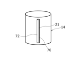
- FIG. 6 is a schematic diagram showing the hollow portion of the electrode body 14 surrounded by a group of tab reinforcing plates 70. Other structures forming the electrode body 14 are omitted from FIG. 6. As shown in FIG. 6, the highly rigid structure of the group of tab reinforcing plates 70 can cover the hollow portion 14a (FIG. 1) of the electrode body 14. This prevents the hollow portion 14a from becoming blocked even if the battery 10 generates abnormal heat. As a result, gas is smoothly exhausted to the outside through the hollow portion 14a, improving the safety of the battery 10.
- the tab reinforcing plate group 70 is composed of the mutually separated negative electrode tab 21 and two reinforcing plates 71, 72. Therefore, when the electrode body 14 is manufactured, the tab reinforcing plate group 70 can be curved along the curved shape of the non-facing portion 60. In this way, compared to the case where the periphery of the hollow portion 14a is covered only with the negative electrode tab 21, it is possible to prevent both ends of the negative electrode tab 21 in the winding direction from becoming angular. This prevents the diameter of the wound electrode body 14 from becoming large, making it difficult to insert the electrode body 14 into the outer can 16. In addition, it is possible to prevent the negative electrode 12 from buckling from the angular parts of the negative electrode tab 21 when the battery 10 is repeatedly charged and discharged.
- Figure 7 is a diagram corresponding to Figure 5 of the negative electrode 40 constituting a battery according to another embodiment.
- the tab reinforcing plate group 74 is composed of the negative electrode tab 21 joined to the outer winding surface 40a of the non-facing portion 60 and the reinforcing plate 75 joined to the inner winding surface 40b of the non-facing portion 60.
- the negative electrode tab 21 and the reinforcing plate 75 are arranged so as to be aligned in the winding direction so as not to overlap in the thickness direction.
- the winding start end P1a of the negative electrode tab 21, which is the winding start end of the tab reinforcing plate group 74, is set as the starting point of the winding revolution, and the negative electrode tab 21 and the reinforcing plate 75 are arranged in a predetermined order so as to be aligned for a total of 0.75 revolutions or more from the starting point toward the winding end side.
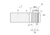
- Figure 8 is a diagram corresponding to Figure 4 of the negative electrode 80 constituting a battery according to another embodiment.
- the tab reinforcing plate group 70a is composed of the negative electrode tab 21 joined to the winding outer surface 80a of the non-facing portion 60 and two reinforcing plates 71, 72.
- the first reinforcing plate 71 and the negative electrode tab 21, and the negative electrode tab 21 and the second reinforcing plate 72 are adjacent to each other, respectively.
- the winding start end P1 of the first reinforcing plate 71 which is the winding start end of the tab reinforcing plate group 70a, is set as the starting point of the winding revolution, and the negative electrode tab 21 and the two reinforcing plates 71, 72 are arranged in a predetermined order from the starting point toward the winding end side for a total of 0.75 revolutions or more.
- the two reinforcing plates 71, 72 and the negative electrode tab 21 are adjacent to each other, so each component of the tab reinforcing plate group 70a can be arranged continuously in the winding direction. This makes it easier to maintain the desired shape of the surrounding shape of the hollow portion of the electrode body, which is formed by the tab reinforcing plate group 70a, even at high temperatures during abnormal heat generation.
- the other configurations and functions are the same as those in Figures 1 to 6.
- FIG. 9 is a diagram corresponding to FIG. 5 of the negative electrode 82 constituting a battery according to another embodiment.
- the tab reinforcing plate group 70b is composed of the negative electrode tab 21 and two reinforcing plates 71a, 72a.
- the thickness of the two reinforcing plates 71a, 72a is smaller than the thickness of the negative electrode tab 21.
- each reinforcing plate 71a, 72a has a thickness of 10% or more and 50% or less of the thickness of the negative electrode tab 21.
- each reinforcing plate 71a, 72a can be curved more smoothly along the curved shape of the non-facing portion 60 of the negative electrode 82 when the electrode body is manufactured.
- each reinforcing plate 71a, 72a in the winding direction. Therefore, it is possible to further suppress the diameter of the wound electrode body 14 from becoming large and making it difficult to insert it into the outer can 16.
- the negative electrode 12 can be further prevented from buckling at the angular portions of the reinforcing plates 71a and 72a.
- the other configurations and functions are the same as those in Figures 1 to 6.
- the tab reinforcing plate group 70, 70a, 70b, 74 includes a negative electrode tab and at least one reinforcing plate, and is configured so that the winding start end of the tab reinforcing plate group 70, 70a, 70b, 74 is the starting point of the winding revolution, and the negative electrode tab and at least one reinforcing plate are arranged in a predetermined order from the starting point toward the winding end side for a total of 0.75 revolutions or more.
- the tab reinforcing plate group may be configured to include three or more reinforcing plates.
Landscapes
- Chemical & Material Sciences (AREA)
- Chemical Kinetics & Catalysis (AREA)
- Electrochemistry (AREA)
- General Chemical & Material Sciences (AREA)
- Engineering & Computer Science (AREA)
- Manufacturing & Machinery (AREA)
- Secondary Cells (AREA)
Priority Applications (3)
| Application Number | Priority Date | Filing Date | Title |
|---|---|---|---|
| CN202480009005.2A CN120615247A (zh) | 2023-01-31 | 2024-01-15 | 圆筒形的非水电解质二次电池 |
| EP24749914.8A EP4661147A1 (en) | 2023-01-31 | 2024-01-15 | Cylindrical non-aqueous electrolyte secondary battery |
| JP2024574385A JPWO2024161960A1 (https=) | 2023-01-31 | 2024-01-15 |
Applications Claiming Priority (2)
| Application Number | Priority Date | Filing Date | Title |
|---|---|---|---|
| JP2023012610 | 2023-01-31 | ||
| JP2023-012610 | 2023-01-31 |
Publications (1)
| Publication Number | Publication Date |
|---|---|
| WO2024161960A1 true WO2024161960A1 (ja) | 2024-08-08 |
Family
ID=92146404
Family Applications (1)
| Application Number | Title | Priority Date | Filing Date |
|---|---|---|---|
| PCT/JP2024/000722 Ceased WO2024161960A1 (ja) | 2023-01-31 | 2024-01-15 | 円筒形の非水電解質二次電池 |
Country Status (4)
| Country | Link |
|---|---|
| EP (1) | EP4661147A1 (https=) |
| JP (1) | JPWO2024161960A1 (https=) |
| CN (1) | CN120615247A (https=) |
| WO (1) | WO2024161960A1 (https=) |
Citations (7)
| Publication number | Priority date | Publication date | Assignee | Title |
|---|---|---|---|---|
| JP2000040529A (ja) * | 1998-07-23 | 2000-02-08 | Toyama Pref Gov | リチウムイオン二次電池とその製造方法 |
| WO2012105362A1 (ja) * | 2011-02-03 | 2012-08-09 | 三洋電機株式会社 | 非水電解液二次電池 |
| JP2012248282A (ja) * | 2011-05-25 | 2012-12-13 | Sanyo Electric Co Ltd | 非水電解質二次電池 |
| JP2013137946A (ja) | 2011-12-28 | 2013-07-11 | Panasonic Corp | 非水電解液二次電池 |
| WO2018061381A1 (ja) * | 2016-09-30 | 2018-04-05 | パナソニックIpマネジメント株式会社 | 非水電解質二次電池 |
| WO2023145674A1 (ja) * | 2022-01-28 | 2023-08-03 | パナソニックエナジー株式会社 | 円筒形の非水電解質二次電池 |
| WO2023163139A1 (ja) * | 2022-02-28 | 2023-08-31 | パナソニックエナジ-株式会社 | 円筒形の非水電解質二次電池 |
-
2024
- 2024-01-15 JP JP2024574385A patent/JPWO2024161960A1/ja active Pending
- 2024-01-15 CN CN202480009005.2A patent/CN120615247A/zh active Pending
- 2024-01-15 WO PCT/JP2024/000722 patent/WO2024161960A1/ja not_active Ceased
- 2024-01-15 EP EP24749914.8A patent/EP4661147A1/en active Pending
Patent Citations (7)
| Publication number | Priority date | Publication date | Assignee | Title |
|---|---|---|---|---|
| JP2000040529A (ja) * | 1998-07-23 | 2000-02-08 | Toyama Pref Gov | リチウムイオン二次電池とその製造方法 |
| WO2012105362A1 (ja) * | 2011-02-03 | 2012-08-09 | 三洋電機株式会社 | 非水電解液二次電池 |
| JP2012248282A (ja) * | 2011-05-25 | 2012-12-13 | Sanyo Electric Co Ltd | 非水電解質二次電池 |
| JP2013137946A (ja) | 2011-12-28 | 2013-07-11 | Panasonic Corp | 非水電解液二次電池 |
| WO2018061381A1 (ja) * | 2016-09-30 | 2018-04-05 | パナソニックIpマネジメント株式会社 | 非水電解質二次電池 |
| WO2023145674A1 (ja) * | 2022-01-28 | 2023-08-03 | パナソニックエナジー株式会社 | 円筒形の非水電解質二次電池 |
| WO2023163139A1 (ja) * | 2022-02-28 | 2023-08-31 | パナソニックエナジ-株式会社 | 円筒形の非水電解質二次電池 |
Non-Patent Citations (1)
| Title |
|---|
| See also references of EP4661147A1 |
Also Published As
| Publication number | Publication date |
|---|---|
| EP4661147A1 (en) | 2025-12-10 |
| JPWO2024161960A1 (https=) | 2024-08-08 |
| CN120615247A (zh) | 2025-09-09 |
Similar Documents
| Publication | Publication Date | Title |
|---|---|---|
| US20190221824A1 (en) | Non-aqueous electrolyte secondary battery | |
| JP6983867B2 (ja) | 非水電解質二次電池 | |
| JP7709293B2 (ja) | 円筒形電池 | |
| JP7720310B2 (ja) | 非水電解質二次電池 | |
| CN112236895B (zh) | 非水电解质二次电池 | |
| JP7634180B2 (ja) | 電池 | |
| WO2018173899A1 (ja) | 非水電解質二次電池 | |
| WO2023281983A1 (ja) | 円筒形電池 | |
| JP2020149881A (ja) | 二次電池 | |
| JP7832192B2 (ja) | 非水電解質二次電池 | |
| WO2023163139A1 (ja) | 円筒形の非水電解質二次電池 | |
| JP7664220B2 (ja) | 密閉電池 | |
| WO2023054005A1 (ja) | 円筒形電池 | |
| US20250210763A1 (en) | Cylindrical battery | |
| US20250273834A1 (en) | Cylindrical battery | |
| JP7809687B2 (ja) | 円筒形電池 | |
| WO2024161960A1 (ja) | 円筒形の非水電解質二次電池 | |
| CN118216031A (zh) | 圆筒形二次电池 | |
| WO2024161982A1 (ja) | 円筒形の非水電解質二次電池 | |
| EP4583298A1 (en) | Cylindrical battery | |
| WO2024048147A1 (ja) | 円筒形電池 | |
| WO2026048538A1 (ja) | 円筒形電池 | |
| WO2025182651A1 (ja) | 円筒形電池 | |
| WO2026048533A1 (ja) | 円筒形二次電池 | |
| WO2024070513A1 (ja) | 円筒形電池 |
Legal Events
| Date | Code | Title | Description |
|---|---|---|---|
| 121 | Ep: the epo has been informed by wipo that ep was designated in this application |
Ref document number: 24749914 Country of ref document: EP Kind code of ref document: A1 |
|
| ENP | Entry into the national phase |
Ref document number: 2024574385 Country of ref document: JP Kind code of ref document: A |
|
| WWE | Wipo information: entry into national phase |
Ref document number: 2024574385 Country of ref document: JP |
|
| WWE | Wipo information: entry into national phase |
Ref document number: 202517069456 Country of ref document: IN |
|
| WWE | Wipo information: entry into national phase |
Ref document number: 202480009005.2 Country of ref document: CN |
|
| WWP | Wipo information: published in national office |
Ref document number: 202517069456 Country of ref document: IN |
|
| NENP | Non-entry into the national phase |
Ref country code: DE |
|
| WWP | Wipo information: published in national office |
Ref document number: 202480009005.2 Country of ref document: CN |
|
| WWP | Wipo information: published in national office |
Ref document number: 2024749914 Country of ref document: EP |