WO2024161633A1 - 自動倉庫管理システムおよびトレイ - Google Patents
自動倉庫管理システムおよびトレイ Download PDFInfo
- Publication number
- WO2024161633A1 WO2024161633A1 PCT/JP2023/003602 JP2023003602W WO2024161633A1 WO 2024161633 A1 WO2024161633 A1 WO 2024161633A1 JP 2023003602 W JP2023003602 W JP 2023003602W WO 2024161633 A1 WO2024161633 A1 WO 2024161633A1
- Authority
- WO
- WIPO (PCT)
- Prior art keywords
- tray
- item
- storage
- automated warehouse
- stored
- Prior art date
- Legal status (The legal status is an assumption and is not a legal conclusion. Google has not performed a legal analysis and makes no representation as to the accuracy of the status listed.)
- Ceased
Links
Images








Classifications
-
- B—PERFORMING OPERATIONS; TRANSPORTING
- B65—CONVEYING; PACKING; STORING; HANDLING THIN OR FILAMENTARY MATERIAL
- B65G—TRANSPORT OR STORAGE DEVICES, e.g. CONVEYORS FOR LOADING OR TIPPING, SHOP CONVEYOR SYSTEMS OR PNEUMATIC TUBE CONVEYORS
- B65G1/00—Storing articles, individually or in orderly arrangement, in warehouses or magazines
- B65G1/02—Storage devices
- B65G1/04—Storage devices mechanical
-
- B—PERFORMING OPERATIONS; TRANSPORTING
- B65—CONVEYING; PACKING; STORING; HANDLING THIN OR FILAMENTARY MATERIAL
- B65G—TRANSPORT OR STORAGE DEVICES, e.g. CONVEYORS FOR LOADING OR TIPPING, SHOP CONVEYOR SYSTEMS OR PNEUMATIC TUBE CONVEYORS
- B65G1/00—Storing articles, individually or in orderly arrangement, in warehouses or magazines
- B65G1/02—Storage devices
- B65G1/14—Stack holders or separators
-
- H—ELECTRICITY
- H05—ELECTRIC TECHNIQUES NOT OTHERWISE PROVIDED FOR
- H05K—PRINTED CIRCUITS; CASINGS OR CONSTRUCTIONAL DETAILS OF ELECTRIC APPARATUS; MANUFACTURE OF ASSEMBLAGES OF ELECTRICAL COMPONENTS
- H05K13/00—Apparatus or processes specially adapted for manufacturing or adjusting assemblages of electric components
-
- H—ELECTRICITY
- H05—ELECTRIC TECHNIQUES NOT OTHERWISE PROVIDED FOR
- H05K—PRINTED CIRCUITS; CASINGS OR CONSTRUCTIONAL DETAILS OF ELECTRIC APPARATUS; MANUFACTURE OF ASSEMBLAGES OF ELECTRICAL COMPONENTS
- H05K13/00—Apparatus or processes specially adapted for manufacturing or adjusting assemblages of electric components
- H05K13/02—Feeding of components
Definitions
- This specification discloses technology related to automated warehouse management systems and trays.
- the storage facility described in Patent Document 1 is equipped with a radio at the entrance.
- the radio communicates wirelessly with both a first radio tag attached to the case and a second radio tag attached to each of the multiple items.
- the acquisition unit described in Patent Document 1 acquires from the radio specific information that identifies the case stored in the first radio tag and identification information that identifies each of the multiple items stored in the second radio tag.
- a tray containing the items is brought into the storage section using a transfer device and stored there, and when the items are removed, the transfer device is used to remove the tray from the storage section and remove the items. For example, if a malfunction of the transfer device occurs or an abnormality occurs with the tray, a worker may remove the tray from the storage section and remove the items. In this configuration, the storage position of the tray may be changed by the worker, and the worker needs to check the tray when removing it from the storage section.
- this specification discloses an automated warehouse management system and a tray that can recognize the tray when storing items in the tray and can recognize the tray when a worker removes the tray from the storage section.
- the automated warehouse management system includes a recognition unit.
- the recognition unit recognizes a first tray identification member that is provided on the tray and can identify the tray, and is provided at a position that can be recognized when the item is stored in the tray, when the item is stored.
- the recognition unit recognizes a second tray identification member that is provided on the tray and can be recognized when a worker removes the tray from the storage section, when the tray is removed.
- the first tray identification member is a tray identification member capable of identifying a tray that can be stored in a storage section of an automated warehouse while storing an item used in a substrate-related operation machine that performs a specified substrate-related operation on a substrate, and is provided at a position that can be recognized when storing the item in the tray.
- the second tray identification member is a tray identification member provided at a position that can be recognized when an operator removes the tray from the storage section.
- a first tray identification member provided in a position that can be recognized when storing an item on a tray can be recognized when storing an item
- a second tray identification member provided in a position that can be recognized when an operator removes a tray from the storage section can be recognized when removing the tray.
- FIG. 1 is a configuration diagram showing an example of the configuration of a board production facility.
- FIG. 2 is a plan view showing an example of a reel.
- FIG. 2B is a side view of the reel of FIG. 2A.
- FIG. 2 is a plan view showing an example of a parts tray.
- FIG. 1 is a front view showing an example of an automated warehouse.
- FIG. 3B is a plan view of the automated warehouse of FIG. 3A.
- FIG. 3B is a perspective view of the interior of the automated warehouse of FIG. 3A.
- FIG. 11 is a perspective view showing an example of a tray capable of accommodating reels.
- FIG. 2 is a perspective view showing an example of a tray housed in a storage section.
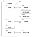
- FIG. 2 is a block diagram showing an example of a control block of an automated warehouse management system.
- 10 is a flowchart showing an example of a control procedure performed by the automated warehouse management system.
- 10 is a schematic diagram showing a state in which tray identification information, storage position information, and item identification information are stored in association with each other.
- FIG. 11 is a front view showing another example of an automated warehouse.
- FIG. 9B is a plan view of the automated warehouse of FIG. 9A.
- FIG. 9C is a front view of the storage unit of FIG. 9B.
- FIG. 2 is a block diagram showing an example of a control block of an automated warehouse.
- 10 is a flowchart showing an example of a control procedure in an automated warehouse.
- FIG. 4 is a side view showing an example of a placement unit.
- the board production facility 80 shown in FIG. 1 includes a substrate-related operation line 10L equipped with a substrate-related operation machine 10, a receiving section 20, a transport vehicle 30, and an automated warehouse 40.
- substrate-related work machines 10 perform a predetermined substrate-related work on a substrate 90.
- the substrate-related work line 10L of the embodiment includes a plurality of (five) substrate-related work machines 10, including a printer 10a, a print inspection machine 10b, a component mounting machine 10c, a reflow oven 10d, and a visual inspection machine 10e, and the substrate 90 is transported in the above order by a substrate transport device.
- the printer 10a prints solder at the component mounting positions on the board 90.
- the print inspection machine 10b inspects the printing condition of the solder printed by the printer 10a.
- the component mounting machine 10c mounts multiple components on the board 90 on which the solder has been printed. There may be one component mounting machine 10c, or multiple component mounting machines 10c. When multiple component mounting machines 10c are provided, multiple components can be mounted on the board 90 by sharing the work among the multiple component mounting machines 10c.
- the component mounting machine 10c is equipped with a component supplying device that supplies components to be mounted on the board 90.
- the component supplying device can supply components using, for example, a feeder equipped with a reel 21a shown in Figures 2A and 2B, or a component tray 21b on which components are arranged as shown in Figure 2C.
- the reel 21a has a component tape 21a2 that contains the components to be mounted on the board 90 wound around a main body 21a1.
- the reel 21a is rotatably and detachably provided on the feeder.
- the tip of the component tape 21a2 is pulled out to a component removal section provided on the feeder, and the components are supplied sequentially.
- the reel 21a can supply relatively small components such as chip components, for example.
- Components are arranged on the component tray 21b.
- the component tray 21b can supply relatively large components such as QFP (Quad Flat Package) and BGA (Ball Grid Array).
- the reflow furnace 10d heats the board 90 on which the components have been mounted by the component mounting machine 10c, melting the solder and performing soldering.
- the appearance inspection machine 10e inspects the mounting state of the components mounted on the board 90 by the component mounting machine 10c.
- the substrate-related work line 10L uses multiple (five) substrate-related work machines 10 to transport substrates 90 in sequence and perform production processes including inspection processes to produce substrate products.
- the substrate-related work line 10L can also be equipped with substrate-related work machines 10 such as a functional inspection machine, a buffer device, a substrate supply device, a substrate reversing device, a shield mounting device, an adhesive application device, and an ultraviolet ray irradiation device, as necessary.
- the multiple (five) substrate-related operation machines 10 and management device 19 that make up substrate-related operation line 10L are capable of communicating with each other via wired or wireless communication.
- the management device 19 controls the multiple (five) substrate-related operation machines 10 that make up substrate-related operation line 10L and monitors the operating status of substrate-related operation line 10L.
- the management device 19 stores various control data for controlling the multiple (five) substrate-related operation machines 10.
- the management device 19 transmits control data to each of the multiple (five) substrate-related operation machines 10.
- each of the multiple (five) substrate-related operation machines 10 transmits its operating status and production status to the management device 19.
- Receiving section 20 and transport vehicle 30 For example, when the item 21 arrives at the receiving section 20, the receiving operation described below is performed. Then, the item 21 is, for example, stored in a storage case, loaded onto the transport vehicle 30, and transported to the automated warehouse 40. After being stored in the automated warehouse 40, the item 21 is supplied to the substrate-related work line 10L as necessary.
- the item 21 is not limited as long as it is used in the substrate-related work machine 10.
- the substrate-related work line 10L is equipped with a printer 10a.
- a solder container that stores solder is included in the item 21.
- the substrate-related work line 10L is also equipped with a component mounting machine 10c.
- a reel 21a on which a component tape 21a2 that stores components to be mounted on the substrate 90 is wound is included in the item 21.
- a component tray 21b on which the components are arranged is included in the item 21.
- an item identification member 22 that can identify the item 21 is attached to the item 21.
- the item identification member 22 can be, for example, a one-dimensional code, a two-dimensional code, or a wireless tag.
- the worker issues an item identification member 22, for example, using an item management device.
- the worker also uses a reading device (for example, a barcode reader) to read the identification member 23 attached to the item 21 by the supplier (vendor).
- the worker can also obtain item information from a database in which item information about the item 21 is registered.
- the worker attaches the item identification member 22 to the surface of the item 21 and places the item 21 in the storage case.
- the storage case can take various forms as long as it can store at least one item 21.
- the storage case may be a tray 60, which will be described later.
- the storage case is also provided with a case identification member that can identify the storage case.
- the case identification member may be, for example, a one-dimensional code, a two-dimensional code, or a wireless tag.
- the worker loads the storage case containing the items 21 onto the transport vehicle 30.
- the transport vehicle 30 can be towed by the worker.
- the transport vehicle 30 can also be an unmanned transport vehicle capable of automatic travel.
- the transport vehicle 30 can also transport the items 21 to the automated warehouse 40 without using a storage case.
- the worker can also transport the items 21 to the automated warehouse 40 without using the transport vehicle 30.
- at least a part of the work performed by the worker described above can be automated using a transport device (e.g., a belt conveyor), an actuator (e.g., a robot arm), an item management device, etc.
- the automated warehouse 40 may take various forms as long as, when the goods 21 are to be stored, the trays 60 containing the goods 21 are carried into the storage section 42 by using the transfer device 40b, and, when the goods 21 are to be removed, the trays 60 are carried out of the storage section 42 by using the transfer device 40b, and the goods 21 are to be removed.
- the storage section 42 of the embodiment is formed, for example, in a roughly rectangular parallelepiped shape.
- the top of the automated warehouse 40 is open, and the interior of the automated warehouse 40 is shown.
- the automated warehouse 40 of the embodiment includes an entry/exit section 41, a storage section 42, a control device 40a, a transfer device 40b, an imaging device 40d, and a display device 40e.
- the entry/exit section 41 includes an opening 41a and a placement section 40c, through which items 21 are entered and removed.
- an opening 41a is provided on the front of the automated warehouse 40.
- the opening 41a is formed to be larger than the items 21 so that the items 21 can be entered or removed.
- the automated warehouse 40 can also have an exit port provided at an opening different from the opening 41a through which items 21 are entered.
- the placement section 40c is provided in the work space near the opening 41a.
- the placement section 40c can temporarily place the item 21 when the item 21 is stored or removed from the warehouse.
- the storing operation of the item 21, which involves bringing in the item 21 and placing it on the placement section 40c can be performed by a worker
- the unloading operation of the item 21, which involves removing the item 21 placed on the placement section 40c can be performed by a worker.
- An imaging device 40d is provided above the placement section 40c. When the item 21 is stored in the automated warehouse 40 through the opening 41a, the imaging device 40d captures an image of the item identification member 22 attached to the item 21 to obtain item identification information.
- the storage section 42 can store a tray 60 that contains an item 21.
- the tray 60 can take various forms as long as it can store the item 21. As shown in Figs. 4 and 5, the tray 60 can have a first storage section 61 that can store at least one type of item 21 (in the case of a reel 21a, referred to as the first reel 21f in this specification) among a plurality of types of items 21 that have different external dimensions.
- the tray 60 can store at least one type of item 21 (in the case of a reel 21a, referred to as the second reel 21s in this specification) that is larger than the external dimensions of the item 21 (item 21 that can be stored in the first storage section 61) and can also have a second storage section 62 that is larger than the first storage section 61.
- the tray 60 can also have both a first storage section 61 and a second storage section 62.
- the first storage section 61 and the second storage section 62 can take various forms.
- the second storage section 62 shown in Figure 4 is provided above the first storage section 61 in the vertical direction (Z-axis direction) and continuous with the storage space of the first storage section 61.
- the first storage section 61 is formed with a first recess 61a capable of accommodating the first reel 21f.
- the second storage section 62 is formed with a second recess 62a capable of accommodating the second reel 21s.
- the first recess 61a is formed as a cylindrical recess with a diameter slightly larger than the outer diameter of the first reel 21f.
- the second recess 62a is formed as a cylindrical recess with a diameter slightly larger than the outer diameter of the second reel 21s.
- the second storage section 62 is provided vertically above the first storage section 61 (Z-axis direction) and continuous with the storage space of the first storage section 61, so that the bottom surface 61b of the first recess 61a and the bottom surface 62b of the second recess 62a are formed in a stepped shape.
- the tray 60 can have at least one first storage section 61 and at least one second storage section 62.
- the tray 60 shown in FIG. 4 has multiple (four in this figure) first storage sections 61 and one second storage section 62. Also, when viewed in the vertical direction (Z-axis direction), the tray 60 has multiple (four) first storage sections 61 and one second storage section 62 formed in a square main body section 60a.
- At least one first reel 21f can be stored in one first storage section 61. At least one second reel 21s can be stored in one second storage section 62. The more the number of first reels 21f stored in one first storage section 61 increases, the more complicated the operation of removing the first reels 21f stored in the first storage section 61 becomes. Also, the more the number of first reels 21f stored in one first storage section 61 increases, the more complicated the management of the first reels 21f becomes. The same can be said about the second reel 21s stored in the second storage section 62.
- each of the multiple (four) first storage sections 61 has a height dimension set so that it can store one first reel 21f
- one second storage section 62 has a height dimension set so that it can store one second reel 21s.
- one tray 60 stores either the first reel 21f or the second reel 21s. This makes it easier to remove the desired reel 21a from the tray 60, and makes it easier to manage the reels 21a.
- first storage section 61 can store multiple types of first reels 21f with different external dimensions (reel diameters).
- second storage section 62 can store multiple types of second reels 21s with different external dimensions (reel diameters).
- at least one of the first storage section 61 and the second storage section 62 can be provided with a pin member 63. The pin member 63 is inserted into the support hole of the reel 21a when the reel 21a is stored.
- the pin member 63 is formed in a cylindrical shape, and the outer diameter of the pin member 63 is set to be slightly smaller than the outer diameter of the support hole of the reel 21a. Furthermore, the height dimension of the pin member 63 provided in the first storage section 61 is set to be smaller than the height dimension of the first storage section 61. Similarly, the height dimension of the pin member 63 provided in the second storage section 62 is set to be smaller than the height dimension of the second storage section 62.
- the tray 60 shown in FIG. 4 is provided with a pin member 63 in the second storage section 62. This allows the second storage section 62 to store multiple types of second reels 21s with different outer dimensions (reel diameters).
- the external dimensions of the first storage section 61 are set so that it can accommodate the reel 21a with the smallest external dimensions (the reel 21a with the smallest reel diameter, referred to herein as the smallest reel) among the reels 21a used in the production of board products.
- the external dimensions of the second storage section 62 are set so that it can accommodate the reel 21a with the largest external dimensions (the reel 21a with the largest reel diameter, referred to herein as the largest reel) among the reels 21a used in the production of board products.
- the main body section 60a is set to be slightly larger than the external dimensions of the second storage section 62.
- the second storage section 62 is provided with a pin member 63.
- the outer dimensions of the tray 60 can therefore be set to match the outer dimensions (reel diameter) of the largest reel. Also, for example, the outer dimensions (reel diameter) of the smallest reel are approximately half the outer dimensions (reel diameter) of the largest reel. Therefore, it is easy to evenly arrange multiple (four) first storage sections 61 in one tray 60, and to evenly store multiple (four) smallest reels. Furthermore, since the second storage section 62 is provided with a pin member 63, the operator can store multiple types of second reels 21s whose outer dimensions (reel diameter) are larger than the smallest reel and smaller than the largest reel in the second storage section 62 without worrying about the outer dimensions (reel diameter) of the second reels 21s.
- the storage section 42 may take various forms as long as it is capable of storing trays 60 containing items 21.
- the storage section 42 has at least one storage body 42g (two in the figure).
- each of the two storage bodies 42g has a storage unit 42u in which multiple storage areas 42r are provided along the vertical direction (Z-axis direction).
- each of the two storage bodies 42g has at least one storage unit 42u (five in the figure) in a predetermined direction (e.g., X-axis direction) perpendicular to the vertical direction (Z-axis direction).
- the storage unit 42u has a pair of support members 42a, 42a that support both ends 60e, 60e of the tray 60 in the width direction (arrow TW direction).
- the pair of support members 42a, 42a are formed with a pair of protrusions that protrude toward the tray 60 at a predetermined interval along the vertical direction (Z-axis direction).
- recesses 60e1, 60e1 are formed at both ends 60e, 60e of the tray 60 in the width direction (arrow TW direction). The recesses 60e1, 60e1 are inserted into the pair of protrusions, so that the tray 60 is supported by the pair of support members 42a, 42a and stored in the storage section 42.
- the number and arrangement of the storage units 42u can be changed as appropriate.
- the number of storage areas 42r in each of the multiple storage units 42u can be changed as appropriate.
- the spacing between the pair of support members 42a, 42a and the vertical (Z-axis) pitch of the pair of protrusions of the storage area 42r can be changed as appropriate to match the size (width, depth, and height) of the tray 60 to be stored.
- recesses can be provided in the pair of support members 42a, 42a, and protrusions can be provided at both ends 60e, 60e in the width direction (direction of arrow TW) of the tray 60.
- the control device 40a is equipped with a known arithmetic device and storage device, and a control circuit is configured.
- the control device 40a is capable of communicating with the transfer device 40b, the imaging device 40d, and the display device 40e, and can control these.
- the automated warehouse 40 is equipped with a storage device that stores item information regarding the item 21, and can also notify the management device 19 of the item information.
- the item information can include the type of parts contained in the reel 21a, the number of parts (remaining number), reel diameter, reel thickness, model and supplier (vendor), humidity control level, expiration date, etc.
- the transfer device 40b transports the tray 60 containing the item 21 into the storage section 42 and stores it therein, and when the item 21 is to be removed from the storage section 42, the transfer device 40b removes the tray 60 from the storage section 42 and removes the item 21 from the storage section 42.
- the automated warehouse 40 picks up the item 21 placed on the placement section 40c during the storing operation of the item 21 and stores it on the tray 60.
- the transfer device 40b moves the tray 60 containing the item 21 to the storage section 42 and stores it there.
- the transfer device 40b moves the tray 60 stored in the storage section 42 to the placement section 40c.
- the automated warehouse 40 picks up the item 21 from the tray 60, and after the tray 60 is evacuated, moves the item 21 to the placement section 40c. This makes it possible to perform the removing operation of the item 21.
- the transfer device 40b may take various forms as long as it can move the tray 60.
- the transfer device 40b may use a known moving mechanism that is movable in three orthogonal directions (X-axis direction, Y-axis direction, and vertical direction (Z-axis direction)).
- the transfer device 40b of the embodiment includes a moving unit 40b1 and a gripping unit 40b2.
- the moving unit 40b1 moves the gripping unit 40b2 in three orthogonal directions (X-axis direction, Y-axis direction, and vertical direction (Z-axis direction)).
- the gripping unit 40b2 grips the tray 60.
- the display device 40e can be a known display device, and displays various data so that the worker can visually confirm them.
- the display device 40e displays, for example, item information about the items 21 stored in the storage section 42 in response to the worker's operation.
- the display device 40e in this embodiment is configured as a touch panel, and the display device 40e also functions as an input device that accepts various operations by the worker.
- the control device 40a can also store in the storage device storage location information, entry/exit information, and storage information of the tray 60 in the storage section 42, and the display device 40e can also display this information.
- the storage location information includes information indicating the storage location of the tray 60.
- the entry/exit information includes information indicating the entry date/time, exit date/time, and number of entry/exit times of the item 21.
- the storage information includes information on at least the humidity of the ambient temperature and humidity of the storage section 42.
- the control device 40a stores in the storage device the position information and entry date/time of the tray 60 when the item 21 is entered.
- the control device 40a stores in the storage device the storage information while the item 21 is in storage.
- the control device 40a stores in the storage device the exit date/time of the item 21 when the item 21 is emptied, and adds one entry/exit time to the number of entries and exits, which is then stored in the storage device.
- Automated warehouse management system 50 For example, when a breakdown occurs in the transfer device 40b or an abnormality occurs in the tray 60, a worker may take the tray 60 out of the storage section 42 to unload the article 21. In this case, the storage position of the tray 60 may be changed by the worker, and the worker needs to check the tray 60 when taking it out of the storage section 42.
- the board production equipment 80 of the embodiment is provided with an automated warehouse management system 50 that manages the automated warehouse 40.
- the automated warehouse management system 50 includes a recognition unit 51.
- the automated warehouse management system 50 can also include a memory unit 52.
- the automated warehouse management system 50 can also include an acquisition unit 53.
- the automated warehouse management system 50 can also include a guidance unit 54.
- the recognition unit 51, the memory unit 52, the acquisition unit 53, and the guidance unit 54 can be provided in various control devices and management devices.
- at least a portion of the recognition unit 51, the memory unit 52, the acquisition unit 53, and the guidance unit 54 can be provided in the control device 40a of the automated warehouse 40.
- At least a portion of the recognition unit 51, the memory unit 52, the acquisition unit 53, and the guidance unit 54 can also be provided in the management device 19.
- At least a portion of the recognition unit 51, the memory unit 52, the acquisition unit 53, and the guidance unit 54 can also be formed on the cloud.
- the automated warehouse management system 50 of the embodiment includes a recognition unit 51, a memory unit 52, an acquisition unit 53, and a guidance unit 54. As shown in FIG. 6, the recognition unit 51, the memory unit 52, the acquisition unit 53, and the guidance unit 54 are provided in the control device 40a of the automated warehouse 40. Furthermore, the automated warehouse management system 50 of the embodiment executes control according to the flowchart shown in FIG. 7.
- the recognition unit 51 performs the determination shown in step S11 and the processes shown in steps S12, S17, and S20.
- the storage unit 52 performs the process shown in step S13.
- the acquisition unit 53 performs the determination shown in steps S14 and S18 and the processes shown in steps S15 and S19.
- the guidance unit 54 performs the process shown in step S16.
- the recognition unit 51 recognizes the first tray identification member 64a when storing the article 21, and recognizes the second tray identification member 64b when removing the tray 60 (steps S11, S12, and S17 shown in FIG. 7). and step S20).
- the first tray identification member 64a is a tray identification member 64, and is provided at a position that can be recognized when the article 21 is placed on the tray 60.
- the second tray identification member 64b is a tray identification member 64 and is provided at a position that can be recognized when an operator removes the tray 60 from the storage section 42.
- the tray identification member 64 is a member that is provided on the tray 60 and can identify the tray 60.
- the tray identification member 64 can be a one-dimensional code, a two-dimensional code, or a wireless tag.
- the first tray identification member 64a and the second tray identification member 64b can take various forms as long as they are tray identification members 64 that are provided in a position that can be recognized in the above-mentioned case. As shown in Figures 4 and 5, in the embodiment, the tray identification member 64 is a one-dimensional code.
- the item 21 in the embodiment, the reel 21a
- the first tray identification member 64a can be provided on the upper surface of the tray 60.
- the automated warehouse 40 is equipped with an imaging device 40d capable of imaging the first tray identification member 64a from above in the vertical direction (Z-axis direction).
- the imaging device 40d may be any known imaging device as long as it can image the first tray identification member 64a.
- the recognition unit 51 can cause the imaging device 40d to image the first tray identification member 64a to obtain tray identification information for the tray 60 stored in the storage unit 42 (step S12 shown in FIG. 7).
- the storage section 42 has multiple storage areas 42r arranged along the vertical direction (Z-axis direction).
- the first tray identification member 64a provided on the trays 60 below the top tray 60. Therefore, the second tray identification member 64b can be provided in a location that can be recognized by an operator when the trays 60 are stored in a specific area of the multiple storage areas 42r.
- the second tray identification member 64b can be provided on the side of the tray 60 that the worker faces when removing the tray 60 from the storage section 42.
- the recognition unit 51 can have the worker read the second tray identification member 64b using a reading device 71 carried by the worker, thereby confirming the tray identification information of the tray 60 that the worker is removing (step S17 shown in FIG. 7). In this way, even if the storage position of the tray 60 has been changed by the worker, the recognition unit 51 can confirm whether the tray 60 that the worker removes from the storage section 42 is correct or not.
- the reading device 71 can be a publicly known barcode reader.
- the automated warehouse 40 is also provided with an entrance through which workers can enter and exit, for example, for maintenance purposes. When a worker enters the interior of the storage section 42 from the entrance, the automated warehouse 40 stops the power supply to the transfer device 40b to ensure the safety of the worker. With the power supply to the transfer device 40b stopped, the worker can enter an area where the transfer device 40b can move and remove the tray 60 from the storage section 42.
- the transfer device 40b is a device provided on a gripping section 40b2 capable of gripping the tray 60, and includes a reading device 40b3 capable of reading the second tray identification member 64b from the horizontal direction (a direction perpendicular to the vertical direction (Z-axis direction)).
- the reading device 40b3 faces the second tray identification member 64b when the gripping section 40b2 grips the tray 60.
- the second tray identification member 64b is a one-dimensional code
- the reading device 40b3 can be a publicly known barcode reader.
- the recognition unit 51 When the transfer device 40b is operating normally, the recognition unit 51 has the reading device 40b3 read the second tray identification member 64b to confirm the tray identification information of the tray 60 that the transfer device 40b removes from the storage unit 42 (step S20 shown in FIG. 7). This allows the recognition unit 51 to confirm whether the tray 60 that the transfer device 40b removes from the storage unit 42 is correct, even if the storage position of the tray 60 has been changed by the worker.
- the recognition unit 51 can obtain tray identification information of the tray 60 stored in the storage unit 42 by having the imaging device 40d capture an image of the first tray identification member 64a. Furthermore, when the worker removes the tray 60 from the storage unit 42, the recognition unit 51 can have the worker read the second tray identification member 64b using the reading device 71 carried by the worker, thereby confirming the tray identification information of the tray 60 that the worker removes. Furthermore, when the transfer device 40b is operating normally, the recognition unit 51 can have the reading device 40b3 read the second tray identification member 64b, thereby confirming the tray identification information of the tray 60 that the transfer device 40b removes from the storage unit 42.
- the recognition unit 51 can also adopt a form that combines the above forms.
- the recognition unit 51 can also recognize the item identification member 22 that is attached to the item 21 and can identify the item 21 when the item 21 is stored (step S12 shown in FIG. 7). Specifically, the item identification member 22 is attached to the item 21 at the receiving unit 20. For example, if the item identification member 22 is a two-dimensional code, the imaging device 40d of the automated warehouse 40 can capture an image of the item identification member 22 attached to the item 21 when the item 21 is stored through the opening 41a, and acquire item identification information.
- the memory unit 52 associates and stores in the memory device 52s the tray identification information acquired by the recognition unit 51 recognizing the first tray identification member 64a, the storage position information indicating the position where the tray 60 is stored in the storage unit 42, and the item identification information acquired by the recognition unit 51 recognizing the item identification member 22 (step S13 shown in FIG. 7).
- the memory device 52s may be any known memory device, database, etc., as long as it is capable of storing the above information.
- the memory device 52s may be provided in the automated warehouse 40 or in the management device 19.
- the memory device 52s may also be formed on the cloud.
- FIG. 8 shows a schematic diagram of a state in which tray identification information, storage position information, and item identification information are stored in association with each other.
- the tray 60 identified by the tray identification information TID1 is associated with being stored in a storage position specified by the storage position information A123.
- the first number in the storage position information A123 indicates that the tray 60 is stored in one of the two storage bodies 42g shown in FIG. 3B (e.g., the storage body 42g at the front of the page).
- the second number in the storage position information A123 indicates that the tray 60 is stored in the storage unit 42u that is a predetermined number (e.g., the second) from the side of the placement section 40c in the storage body 42g.
- the third number in the storage position information A123 indicates that the tray 60 is stored in the storage area 42r that is a predetermined number (e.g., the third) from the top in the vertical direction (Z-axis direction) in the storage unit 42u.
- the tray 60 identified by the tray identification information TID1 is associated with the fact that it contains multiple (four) items 21 identified by item identification information DID1 to item identification information DID4. In addition, it indicates that the item 21 identified by item identification information DID1 can supply the contents indicated in the contents information P1. Similarly, it indicates that the items 21 identified by item identification information DID2 to item identification information DID4 can supply the contents indicated in the contents information P2 to item identification information P4.
- the tray 60 has multiple (five in this figure) storage areas 60r capable of storing items 21 when viewed from above in the vertical direction (Z-axis direction).
- the item 21 identified by the item identification information DID1 is associated with being stored in a storage position specified by storage area information R1 indicating one of the multiple (five) storage areas 60r.
- the item 21 identified by the item identification information DID2 to DID4 is associated with being stored in a storage location specified by the storage area information R2 to R4.
- the memory unit 52 can also store the entry date and time of the item 21, the exit date and time, the ambient temperature and humidity within the automated warehouse 40, etc. in the memory device 52s in association with the information already described.
- the acquisition unit 53 can acquire, based on the tray identification information of the tray 60 stored in the storage unit 42, the storage position information and the item identification information stored in association with the tray identification information from the storage unit 52s. For example, before removing the tray 60 from the storage unit 42, the worker uses the reading device 71 to read the second tray identification member 64b. This allows the recognition unit 51 to acquire the tray identification information of the tray 60 that the worker removes from the storage unit 42.
- the acquisition unit 53 can acquire, based on the tray identification information, the storage position information and the item identification information stored in association with the tray identification information from the storage unit 52s (steps S14 and S15 shown in FIG. 7).
- the reading device 40b3 reads the second tray identification member 64b before the transfer device 40b removes the tray 60 from the storage section 42.
- the obtaining unit 53 can obtain the storage position information and the item identification information that are stored in association with the tray identification information from the storage device 52s based on the tray identification information (steps S18 and S19 shown in FIG. 7).
- the acquisition unit 53 can acquire the storage position information of the tray 60 and the item identification information of the item 21 stored in the tray 60 before the worker or the transfer device 40b removes the tray 60 from the storage unit 42.
- the storage position of the tray 60 may have been changed by the worker.
- the item 21 stored in the tray 60 can be recognized without removing the tray 60 from the storage unit 42.
- the acquisition unit 53 can also acquire, from the storage device 52s, tray identification information and storage position information stored in association with the item identification information based on the item identification information of the item 21. For example, when a worker removes a specific item 21 from the warehouse, the acquisition unit 53 can acquire, from the storage device 52s, tray identification information and storage position information stored in association with the item identification information based on the item identification information of the item 21 (steps S14 and S15 shown in FIG. 7). The above also applies to the case where the transfer device 40b removes the tray 60 from the storage unit 42 when the transfer device 40b is operating normally (steps S18 and S19 shown in FIG. 7).
- the guidance section 54 guides the worker to the position in the storage section 42 of the tray 60 to be removed (e.g., storage position information acquired by the acquisition section 53). Specifically, the guidance section 54 can guide the worker to the position of the storage body 42g shown in FIG. 3B in which the tray 60 is stored, the storage unit 42u shown in FIG. 3A in which the tray 60 is stored in the storage body 42g, and the storage area 42r in which the tray 60 is stored in the storage unit 42u. The guidance section 54 can also display the schematic diagrams shown in FIGS. 3A and 3B on a display device or the like to guide the worker to the position of the tray 60 to be removed.
- the tray 60 of the embodiment also has multiple (five) storage areas 60r capable of storing items 21 when viewed from above in the vertical direction (Z-axis direction).
- the guide unit 54 can guide the worker to the storage area 60r in which the item 21 to be removed is stored, on the tray 60 that the worker removes from the storage unit 42.
- the guide unit 54 can display the schematic diagram shown in FIG. 4 on a display device or the like to guide the worker to the storage area 60r in which the item 21 to be removed is stored.
- the guidance unit 54 can provide guidance to the worker on various display devices, such as the display device 40e of the automated warehouse 40 and the display device of the management device 19.
- the guidance unit 54 can provide guidance on the portable terminal device 72 carried by the worker.
- the worker can receive the necessary guidance using the portable terminal device 72 when removing the tray 60 from the storage unit 42.
- the worker can also use the portable terminal device 72 to obtain various pieces of information obtained by the acquisition unit 53.
- the tray 60 includes a first tray identification member 64a and a second tray identification member 64b.
- the first tray identification member 64a is a tray identification member 64 capable of identifying a tray 60 that can be stored in the storage section 42 of the automated warehouse 40 in a state in which the article 21 used in the substrate-related operating machine 10 is stored therein, and is provided at a position that can be recognized when the article 21 is stored in the tray 60.
- the second tray identification member 64b is a tray identification member 64 that is provided at a position that can be recognized when an operator removes the tray 60 from the storage section 42.
- the tray 60 shown in Figures 4 and 5 has one first tray identification member 64a and one second tray identification member 64b. However, the tray 60 can also have multiple first tray identification members 64a. The tray 60 can also have multiple second tray identification members 64b. For example, if the gripping portion 40b2 of the transfer device 40b is rotatable, the transfer device 40b can rotate the tray 60. Therefore, as shown in Figure 5, the tray 60 only needs to have one second tray identification member 64b on one side of the tray 60 in the removal direction.
- the tray 60 stored in the storage body 42g on the lower side of the paper is stored by the transfer device 40b so that the second tray identification member 64b is arranged on the surface facing the transfer device 40b (the surface on the upper side of the paper). Also, of the two storage bodies 42g, the tray 60 stored in the storage body 42g on the upper side of the paper is stored by the transfer device 40b so that the second tray identification member 64b is arranged on the surface facing the transfer device 40b (the surface on the lower side of the paper).
- the tray 60 needs to have a second tray identification member 64b provided on each of both sides in the removal direction of the tray 60.
- the automated warehouse management method includes a recognition process.
- the recognition process corresponds to the control performed by the recognition unit 51.
- the automated warehouse management method can also include a storage process.
- the storage process corresponds to the control performed by the storage unit 52.
- the automated warehouse management method can also include an acquisition process.
- the acquisition process corresponds to the control performed by the acquisition unit 53.
- the automated warehouse management method can also include a guidance process.
- the guidance process corresponds to the control performed by the guidance unit 54.
- the automated warehouse management method is executed by a control device or the like through processing by the control device.
- the first tray identification member 64a provided in a position that can be recognized when storing the item 21 on the tray 60 can be recognized when storing the item 21.
- the second tray identification member 64b provided in a position that can be recognized when an operator removes the tray 60 from the storage section 42 can be recognized when removing the tray 60.
- What has been described above about the automated warehouse management system 50 can also be similarly applied to the tray 60.
- what has been described above about the automated warehouse management system 50 can also be similarly applied to the automated warehouse management method.
- the board production facility 80 can also include an automated warehouse 400.
- an item 21 to be used in the substrate-related operating machine 10 is stored in the automated warehouse 400, the item 21 is carried into the storage section 420 using the transfer device 400b without being stored in a tray 60, and when the item 21 is to be removed from the warehouse, the item 21 is carried out from the storage section 420 using the transfer device 400b.
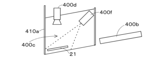
- the automated warehouse 400 is equipped with an entry/exit section 410, a storage section 420, a control device 400a, a transfer device 400b, an imaging device 400d, a display device 400e, and a detection device 400f.
- the entry/exit section 410 is equipped with an opening 410a and a placement section 400c.
- the automated warehouse 400 is formed, for example, in the shape of an octagonal prism.
- the transfer device 400b transfers the items 21 that are not stored in the trays 60.
- the storage section 420 has a plurality of storage units 420u arranged in a circle when viewed from above in the vertical direction (Z-axis direction).
- each of the plurality of storage units 420u has a plurality of storage areas 420r formed by partition plates.
- each of the plurality of storage units 420u has a plurality of types (three types in Fig. 9C) of storage areas 420r (storage area 421r, storage area 422r, storage area 423r) that differ in height in the vertical direction (Z-axis direction), and the storage area 420r can be selected according to the thickness of the items 21.
- the item 21 to be stored in the storage section 420 may come into contact with a part inside the automated warehouse 400 when being stored in the storage section 420. As a result, the item 21 may fall from the storage area 420r. The item 21 may also be stored in a state where it protrudes from the storage area 420r. This may result in damage to the item 21 or a part inside the automated warehouse 400.
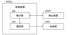
- the automated warehouse 400 is equipped with a detection unit 55 and a selection unit 56.
- the automated warehouse 400 also executes control according to the flowchart shown in FIG. 11.
- the detection unit 55 performs the process shown in step S31.
- the selection unit 56 makes the judgment shown in step S32 and performs the process shown in step S33.
- the detection unit 55 detects the amount of deformation of the item 21 (step S31).
- the detection unit 55 may take various forms as long as it is able to detect the amount of deformation of the item 21.
- the automated warehouse 400 is equipped with a detection device 400f on the loading section 400c that is capable of detecting the amount of three-dimensional deformation of the item 21.
- the detection unit 55 can obtain the amount of deformation of the item 21 by having the detection device 400f detect the item 21 being stored.
- the selection unit 56 selects a storage area 420r that can store the item 21 according to the amount of deformation (steps S32 and S33).
- the storage area 421r shown in FIG. 9C can store an item 21 whose height dimension is up to height H1.
- the storage area 422r can store an item 21 whose height dimension is up to height H2.
- the storage area 423r can store an item 21 whose height dimension is up to height H3.
- the selection unit 56 selects storage area 422r as the storage area 420r for the item 21.
- the selection unit 56 selects storage area 423r as the storage area 420r for the item 21.
- the automated warehouse 400 can prevent malfunctions caused by deformation of the items 21, and can prevent lost work time and damage to parts inside the automated warehouse 400 due to malfunctions. Furthermore, the automated warehouse 400 does not require workers to check for deformation of the items 21, which can reduce the amount of work required.
- the matters described in this specification can be selected and applied as appropriate. The matters described in this specification can be combined as appropriate.
Landscapes
- Engineering & Computer Science (AREA)
- Manufacturing & Machinery (AREA)
- Microelectronics & Electronic Packaging (AREA)
- Mechanical Engineering (AREA)
Priority Applications (2)
| Application Number | Priority Date | Filing Date | Title |
|---|---|---|---|
| PCT/JP2023/003602 WO2024161633A1 (ja) | 2023-02-03 | 2023-02-03 | 自動倉庫管理システムおよびトレイ |
| JP2024574217A JPWO2024161633A1 (https=) | 2023-02-03 | 2023-02-03 |
Applications Claiming Priority (1)
| Application Number | Priority Date | Filing Date | Title |
|---|---|---|---|
| PCT/JP2023/003602 WO2024161633A1 (ja) | 2023-02-03 | 2023-02-03 | 自動倉庫管理システムおよびトレイ |
Publications (1)
| Publication Number | Publication Date |
|---|---|
| WO2024161633A1 true WO2024161633A1 (ja) | 2024-08-08 |
Family
ID=92146266
Family Applications (1)
| Application Number | Title | Priority Date | Filing Date |
|---|---|---|---|
| PCT/JP2023/003602 Ceased WO2024161633A1 (ja) | 2023-02-03 | 2023-02-03 | 自動倉庫管理システムおよびトレイ |
Country Status (2)
| Country | Link |
|---|---|
| JP (1) | JPWO2024161633A1 (https=) |
| WO (1) | WO2024161633A1 (https=) |
Citations (5)
| Publication number | Priority date | Publication date | Assignee | Title |
|---|---|---|---|---|
| JP2014139103A (ja) * | 2007-06-26 | 2014-07-31 | Amazon Technologies Inc | 仕分けシステムおよび方法 |
| WO2019142336A1 (ja) * | 2018-01-19 | 2019-07-25 | 株式会社Fuji | 保管装置およびリール保管方法 |
| WO2021070339A1 (ja) * | 2019-10-10 | 2021-04-15 | 株式会社Fuji | 保管庫 |
| WO2021075049A1 (ja) * | 2019-10-18 | 2021-04-22 | 株式会社Fuji | 保管庫 |
| WO2022153468A1 (ja) * | 2021-01-15 | 2022-07-21 | 株式会社Fuji | リール収容トレイおよび保管庫 |
-
2023
- 2023-02-03 JP JP2024574217A patent/JPWO2024161633A1/ja active Pending
- 2023-02-03 WO PCT/JP2023/003602 patent/WO2024161633A1/ja not_active Ceased
Patent Citations (5)
| Publication number | Priority date | Publication date | Assignee | Title |
|---|---|---|---|---|
| JP2014139103A (ja) * | 2007-06-26 | 2014-07-31 | Amazon Technologies Inc | 仕分けシステムおよび方法 |
| WO2019142336A1 (ja) * | 2018-01-19 | 2019-07-25 | 株式会社Fuji | 保管装置およびリール保管方法 |
| WO2021070339A1 (ja) * | 2019-10-10 | 2021-04-15 | 株式会社Fuji | 保管庫 |
| WO2021075049A1 (ja) * | 2019-10-18 | 2021-04-22 | 株式会社Fuji | 保管庫 |
| WO2022153468A1 (ja) * | 2021-01-15 | 2022-07-21 | 株式会社Fuji | リール収容トレイおよび保管庫 |
Also Published As
| Publication number | Publication date |
|---|---|
| JPWO2024161633A1 (https=) | 2024-08-08 |
Similar Documents
| Publication | Publication Date | Title |
|---|---|---|
| EP3738908B1 (en) | Storage device and storage method | |
| KR101451690B1 (ko) | 부품 실장 시스템, 부품 실장 장치 및 부품 검사 장치 | |
| JP7105915B2 (ja) | 保管庫およびそれを備える保管装置 | |
| JP7266113B2 (ja) | 保管庫 | |
| JP6120516B2 (ja) | 部品補給システム | |
| JP7661368B2 (ja) | リール収容トレイおよび保管庫 | |
| WO2024161633A1 (ja) | 自動倉庫管理システムおよびトレイ | |
| JP7281552B2 (ja) | 保管庫 | |
| JP7167363B2 (ja) | 保管庫 | |
| JP7817284B2 (ja) | 部品案内装置、フィーダラックおよび部品案内方法 | |
| JP7602053B2 (ja) | 物品保管装置 | |
| US11425849B2 (en) | Component supply system | |
| JP7755724B2 (ja) | 案内装置および案内方法 | |
| JP2024164341A (ja) | 物品案内システム | |
| JPWO2019064338A1 (ja) | 部品実装ラインの実装精度測定システム及び実装精度測定方法 | |
| JP7535188B2 (ja) | 張り付き解消装置 | |
| JP2024164342A (ja) | リール補強部材および自動倉庫 | |
| JP2025012760A (ja) | 入庫支援装置および入庫支援方法 | |
| JP2023042808A (ja) | 物品認識装置および物品認識方法 | |
| WO2024236650A1 (ja) | 自動倉庫 | |
| JP7701983B2 (ja) | 部材管理装置および部材管理方法 | |
| WO2024236651A1 (ja) | 自動倉庫 | |
| WO2025052553A1 (ja) | リール管理装置およびリール管理方法 | |
| JP7849391B2 (ja) | 物品管理装置および物品管理方法 | |
| JP2021015349A (ja) | 部品管理システム及び部品管理方法 |
Legal Events
| Date | Code | Title | Description |
|---|---|---|---|
| 121 | Ep: the epo has been informed by wipo that ep was designated in this application |
Ref document number: 23919770 Country of ref document: EP Kind code of ref document: A1 |
|
| WWE | Wipo information: entry into national phase |
Ref document number: 2024574217 Country of ref document: JP |
|
| NENP | Non-entry into the national phase |
Ref country code: DE |
|
| 122 | Ep: pct application non-entry in european phase |
Ref document number: 23919770 Country of ref document: EP Kind code of ref document: A1 |