WO2024161532A1 - 回転装置 - Google Patents
回転装置 Download PDFInfo
- Publication number
- WO2024161532A1 WO2024161532A1 PCT/JP2023/003143 JP2023003143W WO2024161532A1 WO 2024161532 A1 WO2024161532 A1 WO 2024161532A1 JP 2023003143 W JP2023003143 W JP 2023003143W WO 2024161532 A1 WO2024161532 A1 WO 2024161532A1
- Authority
- WO
- WIPO (PCT)
- Prior art keywords
- cylindrical portion
- rotating device
- reinforcing ring
- intermediate cylindrical
- inner cylindrical
- Prior art date
- Legal status (The legal status is an assumption and is not a legal conclusion. Google has not performed a legal analysis and makes no representation as to the accuracy of the status listed.)
- Ceased
Links
Images






Classifications
-
- H—ELECTRICITY
- H02—GENERATION; CONVERSION OR DISTRIBUTION OF ELECTRIC POWER
- H02K—DYNAMO-ELECTRIC MACHINES
- H02K1/00—Details of the magnetic circuit
- H02K1/06—Details of the magnetic circuit characterised by the shape, form or construction
- H02K1/22—Rotating parts of the magnetic circuit
- H02K1/24—Rotor cores with salient poles ; Variable reluctance rotors
- H02K1/246—Variable reluctance rotors
-
- H—ELECTRICITY
- H02—GENERATION; CONVERSION OR DISTRIBUTION OF ELECTRIC POWER
- H02K—DYNAMO-ELECTRIC MACHINES
- H02K1/00—Details of the magnetic circuit
- H02K1/06—Details of the magnetic circuit characterised by the shape, form or construction
- H02K1/22—Rotating parts of the magnetic circuit
- H02K1/27—Rotor cores with permanent magnets
- H02K1/2706—Inner rotors
- H02K1/272—Inner rotors the magnetisation axis of the magnets being perpendicular to the rotor axis
- H02K1/274—Inner rotors the magnetisation axis of the magnets being perpendicular to the rotor axis the rotor consisting of two or more circumferentially positioned magnets
- H02K1/2753—Inner rotors the magnetisation axis of the magnets being perpendicular to the rotor axis the rotor consisting of two or more circumferentially positioned magnets the rotor consisting of magnets or groups of magnets arranged with alternating polarity
- H02K1/278—Surface mounted magnets; Inset magnets
-
- H—ELECTRICITY
- H02—GENERATION; CONVERSION OR DISTRIBUTION OF ELECTRIC POWER
- H02K—DYNAMO-ELECTRIC MACHINES
- H02K49/00—Dynamo-electric clutches; Dynamo-electric brakes
- H02K49/10—Dynamo-electric clutches; Dynamo-electric brakes of the permanent-magnet type
- H02K49/102—Magnetic gearings, i.e. assembly of gears, linear or rotary, by which motion is magnetically transferred without physical contact
-
- H—ELECTRICITY
- H02—GENERATION; CONVERSION OR DISTRIBUTION OF ELECTRIC POWER
- H02K—DYNAMO-ELECTRIC MACHINES
- H02K7/00—Arrangements for handling mechanical energy structurally associated with dynamo-electric machines, e.g. structural association with mechanical driving motors or auxiliary dynamo-electric machines
- H02K7/10—Structural association with clutches, brakes, gears, pulleys or mechanical starters
- H02K7/11—Structural association with clutches, brakes, gears, pulleys or mechanical starters with dynamo-electric clutches
-
- H—ELECTRICITY
- H02—GENERATION; CONVERSION OR DISTRIBUTION OF ELECTRIC POWER
- H02K—DYNAMO-ELECTRIC MACHINES
- H02K7/00—Arrangements for handling mechanical energy structurally associated with dynamo-electric machines, e.g. structural association with mechanical driving motors or auxiliary dynamo-electric machines
- H02K7/18—Structural association of electric generators with mechanical driving motors, e.g. with turbines
- H02K7/1807—Rotary generators
- H02K7/1823—Rotary generators structurally associated with turbines or similar engines
- H02K7/183—Rotary generators structurally associated with turbines or similar engines wherein the turbine is a wind turbine
- H02K7/1838—Generators mounted in a nacelle or similar structure of a horizontal axis wind turbine
Definitions
- This application relates to a rotating device.
- a rotating device having a triple cylindrical structure in which an inner cylindrical portion, an intermediate cylindrical portion, and an outer cylindrical portion are arranged concentrically is known.
- the three cylindrical portions each function as a stator or a rotor.
- a rotating device in which the intermediate cylindrical portion serves as a stator and the inner cylindrical portion and the outer cylindrical portion serve as rotors is called a magnetic gear device.
- rotational torque is transmitted between the inner cylindrical portion and the outer cylindrical portion via the intermediate cylindrical portion provided with magnetic pole pieces. For this reason, the magnetic gear device is applied to, for example, speed increasers for wind power generation devices and automobile transmissions.
- a rotating device in which the outer cylindrical portion serves as a stator and the inner cylindrical portion and the intermediate cylindrical portion serve as rotors is called a magnetic geared rotating electric machine.
- a magnetic geared rotating electric machine when the intermediate cylindrical portion provided with magnetic pole pieces is rotated by an external power source, the inner cylindrical portion provided with a magnet rotates at a predetermined speed increase ratio.
- a current is generated in a coil provided in the outer cylindrical portion due to a change in magnetic flux caused by the rotation of the inner cylindrical portion. For this reason, magnetic-geared rotating electric machines are used, for example, in generators for wind power generation equipment.
- the radial width of the intermediate cylindrical portion is reduced to strengthen the magnetic coupling between the inner cylindrical portion and the outer cylindrical portion.
- the intermediate cylindrical portion also has magnetic pole pieces arranged in the circumferential direction. These magnetic pole pieces are made by stacking magnetic materials such as electromagnetic steel sheets in the axial direction.
- the magnetic pole pieces of the intermediate cylindrical portion are subjected to electromagnetic forces in the radial direction as well as gravity due to their own weight.
- the magnetic pole pieces of the intermediate cylindrical portion are subjected to electromagnetic forces in the radial direction as well as gravity due to their own weight and centrifugal force due to rotation.
- the intermediate cylindrical portion is required to have the rigidity to prevent deformation due to the electromagnetic forces acting on the magnetic pole pieces and gravity due to their own weight.
- a conventional rotating device that addresses these problems is one that includes an intermediate cylindrical section in which connecting members and pole pieces arranged alternately in the circumferential direction are fastened in the axial direction via a reinforcing ring.
- the reinforcing ring is connected to end plates arranged at both ends of the intermediate cylindrical section together with the connecting members by through bolts.
- a protrusion is provided on the outer periphery of the reinforcing ring that contacts the connecting members and pole pieces from the radial outside.
- This application has been made to solve the above-mentioned problems, and aims to provide a rotating device with improved rigidity of the intermediate cylindrical portion.
- the rotating device of the present application has an inner cylindrical portion, an intermediate cylindrical portion, and an outer cylindrical portion arranged concentrically around the rotation axis, and the intermediate cylindrical portion has an annular portion in which magnetic pole pieces and spacers composed of a continuum along the rotation axis are arranged alternately in the circumferential direction, and a reinforcing ring that supports the annular portion.
- the reinforcing ring is arranged on the inner diameter side of the annular portion, and the outer peripheral surface of the reinforcing ring is fastened to the inner peripheral surface of the spacer.
- the reinforcing ring is disposed on the inner diameter side of the annular portion, and the outer peripheral surface of the reinforcing ring is fastened to the inner peripheral surface of the spacer, thereby improving the rigidity of the intermediate cylindrical portion.
- FIG. 11 is a cross-sectional view of a rotation device according to a second embodiment.
- FIG. 11 is a cross-sectional view of a rotation device according to a second embodiment.
- FIG. 11 is an exploded perspective view of a rotating device according to a second embodiment.
- FIG. 11 is a cross-sectional view of a rotation device according to a third embodiment.
- FIG. 11 is a cross-sectional view of a rotation device according to a fourth embodiment.
- FIG. 13 is a cross-sectional view of a rotation device according to a fifth embodiment.
- FIG. 13 is a cross-sectional view of a rotation device according to a sixth embodiment.
- FIG. 13 is a perspective view of an intermediate cylindrical portion of a rotation device according to a seventh embodiment.
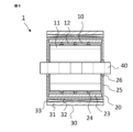
- Embodiment 1. 1 and 2 are cross-sectional views of a rotating device according to a first embodiment.
- FIG. 1 is a cross-sectional view of a plane perpendicular to the rotation axis of the rotating device 1.
- FIG. 2 is a cross-sectional view of a plane parallel to the rotation axis of the rotating device 1.
- the rotating device 1 is a magnetic gear device.
- the rotating device 1 of this embodiment includes an inner cylindrical portion 10, an intermediate cylindrical portion 20 arranged on the outer circumferential side of the inner cylindrical portion 10 with a gap therebetween, and an outer cylindrical portion 30 arranged on the outer circumferential side of the intermediate cylindrical portion 20 with a gap therebetween.
- the inner cylindrical portion 10, the intermediate cylindrical portion 20, and the outer cylindrical portion 30 are arranged concentrically around the rotation axis 40. Note that in FIGS. 1 and 2, a case for housing the inner cylindrical portion 10, the intermediate cylindrical portion 20, and the outer cylindrical portion 30 therein is omitted.
- the rotating shaft 40 is cylindrical.
- the direction parallel to the rotating shaft 40 is called the axial direction
- the direction perpendicular to the rotating shaft 40 is called the radial direction
- the direction in which the rotating shaft rotates is called the circumferential direction.
- the inner diameter side is the direction approaching the rotating shaft 40 in the radial direction
- the outer diameter side is the direction moving away from the rotating shaft 40 in the radial direction.
- the inner cylindrical portion 10 has an inner cylindrical core 11 and inner cylindrical magnets 12 arranged in a line in the circumferential direction on the outer circumferential surface of the inner cylindrical core 11.
- the inner cylindrical core 11 is fastened to a rotating shaft 40.
- the inner cylindrical magnets 12 are permanent magnets. Furthermore, the inner cylindrical magnets 12 have south and north poles arranged alternately in the circumferential direction and are divided in the axial direction.
- the inner cylindrical core 11 is made of a magnetic material, for example, electromagnetic steel sheets stacked in the axial direction.
- the intermediate cylindrical portion 20 has an annular portion 23 formed by circumferentially alternatingly arranging spacers 21 and pole pieces 22, and a reinforcing ring 24 that supports the annular portion 23 from its inner peripheral surface.
- the intermediate cylindrical portion 20 also has end plates 25 at both axial ends.
- the annular portion 23 formed by the spacers 21 and pole pieces 22 is supported by the end plates 25 at both axial ends.
- the end plates 25 are connected to the rotating shaft 40 via bearings 26.
- the pole pieces 22 are made of a magnetic material, such as electromagnetic steel plates laminated in the axial direction.
- the spacers 21, reinforcing rings 24, and end plates 25 are made of a non-magnetic material, such as austenitic stainless steel, aluminum, or resin.
- the outer cylindrical portion 30 has a cylindrical outer cylindrical core 31 and outer cylindrical magnets 32 arranged in a line in the circumferential direction on the inner peripheral surface of the outer cylindrical core 31.
- the outer cylindrical magnets 32 are permanent magnets. Furthermore, the outer cylindrical magnets 32 have south poles and north poles arranged alternately in the circumferential direction.
- the outer cylindrical core 31 is made of a magnetic material, for example, electromagnetic steel sheets stacked in the axial direction.
- FIG. 3 is an exploded perspective view of the rotating device 1 of this embodiment. Note that the end plate 25 and bearing 26 of the intermediate cylindrical portion 20 are omitted in FIG. 3.
- the inner cylindrical magnet 12 is divided into 14 pieces in the circumferential direction and 4 pieces in the axial direction. However, the inner cylindrical magnet 12 does not necessarily have to be divided in the axial direction.
- the annular portion 23 of the intermediate cylindrical portion 20 is configured by alternatingly arranging the magnetic pole pieces 22, which are divided into 24 pieces in the circumferential direction, and the spacer 21, which is configured as a continuum along the rotation axis. Three reinforcing rings 24 are arranged on the inner diameter side of the annular portion 23.
- the outer cylindrical magnet 32 is divided into 18 pieces in the circumferential direction.
- the rotating device 1 of this embodiment is a magnetic gear device. Therefore, the intermediate cylindrical portion 20 is a stator, and the inner cylindrical portion 10 and the outer cylindrical portion 30 are rotors. Therefore, the inner cylindrical portion 10 rotates together with the rotating shaft 40. The outer cylindrical portion 30 and the inner cylindrical portion 10 rotate relatively.
- the intermediate cylindrical portion 20 is fixed to a case or the like via an end plate 25.
- the outer cylindrical portion 30 is supported rotatably on the rotating shaft 40 via a bearing.
- an attractive force and a repulsive force act between the inner cylindrical magnet 12 and the outer cylindrical magnet 32 via the magnetic pole piece 22 of the intermediate cylindrical portion 20.
- the attractive force and the repulsive force acting between the inner cylindrical magnet 12 and the outer cylindrical magnet 32 transmit the rotational torque of the inner cylindrical portion 10 to the rotational torque of the outer cylindrical portion 30.
- the magnetic gear device when the inner cylindrical portion 10 and the outer cylindrical portion 30 are rotating, an electromagnetic force acts radially on the intermediate cylindrical portion 20 due to the magnetic forces of the inner cylindrical magnet 12 and the outer cylindrical magnet 32. Furthermore, when the magnetic gear device is used as a speed increaser for a wind power generation device, the outer diameter of the intermediate cylindrical portion 20 is 10 m or more, and the radial thickness of the annular portion 23 is also approximately 40 mm. Therefore, the effect of gravity due to the weight of the intermediate cylindrical portion 20 cannot be ignored. As a result, the intermediate cylindrical portion 20 may be deformed by the electromagnetic force and gravity. In particular, both axial ends of the intermediate cylindrical portion 20 are fixed by end plates and are therefore not easily deformed, but the central portion in the axial direction is easily deformed radially.
- the reinforcing ring 24 is disposed on the inner diameter side of the annular portion 23, and the outer circumferential surface of the reinforcing ring 24 is fastened to the inner circumferential surface of the spacer 21 disposed between the pole pieces 22.
- the inner circumferential surface of the spacer 21, which has pole pieces 22 on both circumferential sides is fastened to the outer circumferential surface of the reinforcing ring 24.
- an intermediate cylindrical portion configured in this manner, even when electromagnetic forces and gravity act radially on the reinforcing ring 24, the circumferential stress generated in the reinforcing ring 24 is reduced, thereby improving the rigidity of the intermediate cylindrical portion.
- the spacer 21 is configured as a continuous body without joints from the end plate 25 at one end in the axial direction to the end plate 25 at the other end.
- the spacer 21 is configured as a continuous body along the rotation axis.
- the spacer 21 configured in this way has higher rigidity than a spacer that is divided along the axial direction and has joints, improving the rigidity of the intermediate cylindrical portion.
- the thickness of the portion fastened to the reinforcing ring 24 may be made thicker than the thickness of the other portions. In this way, the stress generated at the fastening portion between the spacer and the reinforcing ring is reduced, and the rigidity of the intermediate cylindrical portion can be improved.
- the spacer 21 and the reinforcing ring 24 are fastened using a fastening method that can transmit the radially outward load acting on the spacer 21 to the reinforcing ring 24.
- Fastening methods that can be used include, for example, mechanical fastening methods such as bolting, riveting, and crimping; material fastening methods such as welding, pressure welding, friction welding, and solid-state welding; and chemical fastening methods such as adhesion and vapor deposition.
- the spacer 21 and the reinforcing ring 24 may be an integral structure.
- the radial displacement ⁇ is proportional to the square of the average radius r. If we assume that the radially outward load acting on the intermediate cylindrical portion corresponds to the internal pressure acting on the intermediate cylindrical portion, it can be seen that if the radial thickness of the reinforcing ring is constant, the smaller the average radius of the reinforcing ring, the smaller the radial displacement.
- the average radius of the reinforcing ring 24 can be reduced by fastening the reinforcing ring 24 to the inner peripheral surface of the spacer 21. This reduces the displacement of the reinforcing ring 24, which results in an improvement in the rigidity of the intermediate cylindrical portion. Furthermore, from formula (1), if the radius of the innermost peripheral surface of the reinforcing ring 24 is further reduced, the average radius will be further reduced, which results in an improvement in the rigidity of the intermediate cylindrical portion.
- the annular portion and the reinforcing link are fastened in the radial direction. Therefore, the electromagnetic force acting on the intermediate cylindrical portion acts in a direction parallel to the fastening direction. This results in a tensile load acting on the fastening portion. That is, in the intermediate cylindrical portion of the rotating device of this embodiment, the direction in which the fastening force of the fastening portion acts and the direction in which the load acts are parallel. As a result, in the rotating device of this embodiment, the fastening force of the fastening portion acts directly as a resistance force against the load, so the rigidity of the intermediate cylindrical portion can be improved. In particular, high-strength fastening methods such as bolt fastening that exert a fastening force in the axial direction are effective.
- both axial ends of the spacer are fastened to the end plates with axial tension applied.
- the total axial length of the pole pieces before the end plates are attached is set to be longer than the total axial length of the spacers within the elastic deformation range of the spacers.
- the end plates and the spacers are fastened while compressing the pole pieces with the end plates from both axial ends.
- the end plates and the spacers can be fastened, for example, by bolting or welding.
- an axial compressive force acts on the pole pieces and an axial tensile force acts on the spacers.
- the laminated structure of the electromagnetic steel sheets can be maintained without adopting a special structure for maintaining the laminated structure.
- the inner diameter side end of the reinforcing ring 24 of the intermediate cylindrical portion 20 is located on the inner diameter side of the outer diameter side end of the inner cylindrical magnet 12 of the inner cylindrical portion 10.
- the inner cylindrical portion which is the rotor
- the intermediate cylindrical portion which is the stator
- the inner and outer cylindrical portions which are the rotors
- the rotating shaft is fixed and does not rotate.
- the intermediate cylindrical portion 20 has three reinforcing rings 24, but it is sufficient if it has one or more.
- Embodiment 2. 4 and 5 are cross-sectional views of a rotating device according to a second embodiment.
- FIG. 4 is a cross-sectional view of a plane perpendicular to the rotation axis of the rotating device 1.
- FIG. 5 is a cross-sectional view of a plane parallel to the rotation axis of the rotating device.
- the rotating device 1 is a magnetic-geared rotating electric machine.
- the rotating device 1 of this embodiment includes an inner cylindrical portion 10, an intermediate cylindrical portion 20 arranged on the outer circumferential side of the inner cylindrical portion 10 with a gap therebetween, and an outer cylindrical portion 30 arranged on the outer circumferential side of the intermediate cylindrical portion 20 with a gap therebetween.
- the inner cylindrical portion 10, the intermediate cylindrical portion 20, and the outer cylindrical portion 30 are arranged concentrically around the rotation axis 40. Note that in FIGS. 4 and 5, a case for housing the inner cylindrical portion 10, the intermediate cylindrical portion 20, and the outer cylindrical portion 30 therein is omitted.
- the configuration of the inner cylindrical portion 10 and the intermediate cylindrical portion 20 is the same as that of the rotating device of embodiment 1.
- the outer cylindrical portion 30 has a cylindrical outer cylindrical core 31, an outer cylindrical magnet 32, and an outer cylindrical coil 33.
- the outer cylindrical core 31 has a plurality of teeth 31a that protrude from the cylindrical core back toward the inner diameter side. Slots are formed between the teeth 31a.
- the outer cylindrical coil 33 is wound around the teeth 31a using these slots.
- the outer cylindrical magnet 32 is disposed within the slot on the inner diameter side of the outer cylindrical coil 33.
- FIG. 6 is an exploded perspective view of the rotating device 1 of this embodiment. Note that the end plate 25 and the bearing 26 of the intermediate cylindrical portion 20 are omitted in FIG. 6. To avoid complication, the outer cylindrical coil 33 is also omitted in FIG. 6.
- the inner cylindrical magnet 12 is divided into 14 pieces in the circumferential direction and 4 pieces in the axial direction.
- the annular portion 23 of the intermediate cylindrical portion 20 is configured by alternately arranging the magnetic pole pieces 22, which are divided into 24 pieces in the circumferential direction, and the spacer 21, which is configured as a continuum along the rotation axis.
- Three reinforcing rings 24 are arranged on the inner periphery of the annular portion 23. Furthermore, 18 pieces of each of the outer cylindrical magnets 32 and the outer cylindrical coils 33 are arranged in the circumferential direction.
- the rotating device 1 of this embodiment is a magnetic-geared rotating electric machine. Therefore, the outer cylindrical portion 30 is the stator, the inner cylindrical portion 10 is the high-speed rotor, and the intermediate cylindrical portion 20 is the low-speed rotor. Therefore, the inner cylindrical portion 10 rotates together with the rotating shaft 40, and the intermediate cylindrical portion 20 is rotatably supported on the rotating shaft 40 via the bearing 26. Although not shown, the outer cylindrical portion 30 is fixed to the case. For example, when the intermediate cylindrical portion 20 is rotated by an external power, attractive and repulsive forces act between the inner cylindrical magnet 12 and the outer cylindrical magnet 32 via the magnetic pole piece 22 of the intermediate cylindrical portion 20. The attractive and repulsive forces acting between the inner cylindrical magnet 12 and the outer cylindrical magnet 32 transmit the rotational torque of the intermediate cylindrical portion 20 to the rotational torque of the inner cylindrical portion 10.
- the reinforcing ring 24 is disposed on the inner diameter side of the annular portion 23, and the outer circumferential surface of the reinforcing ring 24 is fastened to the inner circumferential surface of the spacer 21 disposed between the pole pieces 22.
- the inner circumferential surface of the spacer 21, which has pole pieces 22 on both circumferential sides is fastened to the outer circumferential surface of the reinforcing ring 24.
- the circumferential stress generated in the reinforcing ring 24 is reduced even when electromagnetic force, centrifugal force, and gravity act radially on the reinforcing ring 24, thereby improving the rigidity of the intermediate cylindrical portion.
- the average radius of the reinforcing ring 24 can be reduced by fastening the reinforcing ring 24 to the inner peripheral surface of the spacer 21. This reduces the displacement of the reinforcing ring 24, which results in improved rigidity of the intermediate cylindrical portion.
- the annular portion and the reinforcing link are fastened along the radial direction. Therefore, the electromagnetic force, centrifugal force, and gravity acting on the intermediate cylindrical portion act in a direction parallel to the fastening direction. As a result, a tensile load acts on the fastening portion. That is, in the intermediate cylindrical portion of the rotating device of this embodiment, the direction in which the fastening force of the fastening portion acts and the direction in which the load acts are parallel. As a result, in the rotating device of this embodiment, the fastening force of the fastening portion acts directly as a resisting force against the load, thereby improving the rigidity of the intermediate cylindrical portion.
- the inner diameter side end of the reinforcing ring 24 of the intermediate cylindrical portion 20 is located on the inner diameter side of the outer diameter side end of the inner cylindrical magnet 12 of the inner cylindrical portion 10.
- the gap between the inner cylindrical magnet 12 of the inner cylindrical portion 10 and the magnetic pole piece 22 of the intermediate cylindrical portion 20 is reduced, increasing the rigidity of the reinforcing ring 24 while preventing a decrease in rotation conversion efficiency.
- the intermediate cylindrical portion 20 has three reinforcing rings 24, but it is sufficient to have one or more.
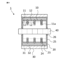
- Fig. 7 is a cross-sectional view of a rotating device according to a third embodiment.
- Fig. 7 is a cross-sectional view of a plane parallel to the rotation axis of the rotating device.
- the rotating device 1 of this embodiment will be described as a magnetic gear device. Therefore, the basic configuration of the rotating device of this embodiment is similar to the configuration of the rotating device of the first embodiment.
- a notch 11a is formed around the entire circumference of the inner cylindrical core 11 of the inner cylindrical portion 10.
- This notch 11a is formed in a position facing the reinforcing ring 24 of the intermediate cylindrical portion 20.
- the inner cylindrical magnet 12 is also divided into four parts in the axial direction corresponding to the notch 11a.
- the reinforcing ring 24 is positioned away from the inner wall of this notch 11a. Therefore, the inner diameter side end of the reinforcing ring 24 of the intermediate cylindrical portion 20 can be positioned on the inner diameter side of the outer diameter side end of the inner cylindrical core 11. As a result, the average radius of the reinforcing ring 24 can be further reduced, which results in improved rigidity of the intermediate cylindrical portion.
- the radial width of the reinforcing ring 24 can be further increased, thereby further increasing the rigidity of the reinforcing ring 24 itself, and as a result, the rigidity of the intermediate cylindrical portion 20 can be further improved.
- the intermediate cylindrical portion 20 has three reinforcing rings 24, but it is sufficient if it has one or more. Also, although the rotating device of this embodiment has been described as a magnetic gear device, the same effect can be obtained with a magnetic geared rotating electric machine.
- Fig. 8 is a cross-sectional view of a rotation device according to embodiment 4.
- Fig. 8 is a cross-sectional view of a plane parallel to the rotation axis of the rotation device.
- the basic configuration of the rotation device of this embodiment is similar to the configuration of the rotation device of embodiment 3.
- a notch 11a is formed around the entire circumference of the inner cylindrical core 11 of the inner cylindrical portion 10.
- This notch 11a is formed in a position facing the reinforcing ring 24 of the intermediate cylindrical portion 20.
- the inner cylindrical magnet 12 is also divided into four in the axial direction corresponding to the notch 11a.
- the reinforcing ring 24 is positioned away from the inner wall of this notch 11a. Therefore, the inner diameter side end of the reinforcing ring 24 of the intermediate cylindrical portion 20 can be positioned on the inner diameter side of the outer diameter side end of the inner cylindrical core 11. As a result, the average radius of the reinforcing ring 24 can be further reduced, which results in improved rigidity of the intermediate cylindrical portion.
- the intermediate cylindrical portion 20 is provided with three reinforcing rings 24.
- the radial width of the reinforcing rings 24 located at the center in the axial direction is smaller than the radial width of the reinforcing rings 24 located at the end in the axial direction. Therefore, the axial mass distribution of the intermediate cylindrical portion 20 is greater at the end than at the center.
- the intermediate cylindrical section 20 is fixed at both axial ends by end plates 25. Therefore, the deformation of the intermediate cylindrical section 20 due to gravity is greater in the central section in the axial direction.
- the axial mass distribution of the intermediate cylindrical section 20 is smaller at the central section than at the ends, so that the deformation of the central section of the intermediate cylindrical section 20 due to gravity can be reduced.
- the intermediate cylindrical portion 20 has three reinforcing rings 24, but it may have four or more. Also, although the rotating device of this embodiment has been described as a magnetic gear device, the same effect can be obtained with a magnetic geared rotating electric machine.
- Fig. 9 is a cross-sectional view of a rotation device according to embodiment 5.
- Fig. 9 is a cross-sectional view of a plane parallel to the rotation axis of the rotation device.
- the basic configuration of the rotation device of this embodiment is similar to the configuration of the rotation device of embodiment 3.
- a notch 11a is formed around the entire circumference of the inner cylindrical core 11 of the inner cylindrical portion 10.
- This notch 11a is formed in a position facing the reinforcing ring 24 of the intermediate cylindrical portion 20.
- the inner cylindrical magnet 12 is also divided into four parts in the axial direction corresponding to the notch 11a.
- the reinforcing ring 24 is positioned away from the inner wall of this notch 11a. Therefore, the inner diameter side end of the reinforcing ring 24 of the intermediate cylindrical portion 20 can be positioned on the inner diameter side of the outer diameter side end of the inner cylindrical core 11. As a result, the average radius of the reinforcing ring 24 can be further reduced, which results in improved rigidity of the intermediate cylindrical portion.
- the intermediate cylindrical portion 20 is provided with three reinforcing rings 24. If the axial distance between the reinforcing ring 24 located at the axial end side and the end plate 25 is L1, and the axial distance between the reinforcing rings 24 located at the axial center side is L2, L1 is smaller than L2. In addition, the radial width of the three reinforcing rings 24 is the same. Therefore, the axial mass distribution of the intermediate cylindrical portion 20 is greater at the end side than at the center side.
- the annular portion 23 of the intermediate cylindrical portion 20 has both axial ends fixed by end plates 25. Therefore, the deformation of the intermediate cylindrical portion 20 caused by gravity is greater in the central portion in the axial direction.
- the axial mass distribution of the intermediate cylindrical portion 20 is smaller in the central portion than in the end portions, so that the deformation of the central portion of the intermediate cylindrical portion 20 caused by gravity can be reduced.
- the intermediate cylindrical portion 20 has three reinforcing rings 24, but it is sufficient if it has two or more. Also, although the rotating device of this embodiment has been described as a magnetic gear device, the same effect can be obtained with a magnetic geared rotating electric machine.
- Fig. 10 is a cross-sectional view of a rotation device according to embodiment 6.
- Fig. 10 is a cross-sectional view of a plane parallel to the rotation axis of the rotation device.
- the basic configuration of the rotation device of this embodiment is similar to the configuration of the rotation device of embodiment 3.
- a notch 11a is formed around the entire circumference of the inner cylindrical core 11 of the inner cylindrical portion 10.
- This notch 11a is formed in a position facing the reinforcing ring 24 of the intermediate cylindrical portion 20.
- the inner cylindrical magnet 12 is also divided into four parts in the axial direction corresponding to the notch 11a.
- the reinforcing ring 24 is positioned away from the inner wall of this notch 11a. Therefore, the inner diameter side end of the reinforcing ring 24 of the intermediate cylindrical portion 20 can be positioned on the inner diameter side of the outer diameter side end of the inner cylindrical core 11. As a result, the average radius of the reinforcing ring 24 can be further reduced, which results in improved rigidity of the intermediate cylindrical portion.
- the axial width of the cutout portion 11a is set large enough so that the reinforcing ring 24 does not come into contact with the inner cylindrical core 11. However, if the axial width of the inner cylindrical magnet 12 is reduced to match the width of the cutout portion 11a, the torque transmission efficiency of the magnetic gear device will decrease.
- the width of the axial gap between the inner cylindrical magnets 12 is made smaller than the width of the cutout portion 11a.
- the axial thickness of the reinforcing ring 24 is set to be smallest at the position axially opposite the inner cylindrical magnet 12.
- the axial gap between the reinforcing ring 24 and the inner cylindrical core 11 and the inner cylindrical magnet 12 can be increased, preventing contact between the reinforcing ring 24 and the inner cylindrical portion 10.
- a decrease in the torque transmission efficiency of the magnetic gear device can be prevented.
- the intermediate cylindrical portion 20 has three reinforcing rings 24, but it is sufficient if it has one or more. Also, although the rotating device of this embodiment has been described as a magnetic gear device, the same effect can be obtained with a magnetic geared rotating electric machine.
- a notch is provided in the inner cylindrical core so that the inner diameter side end of the reinforcing ring is positioned on the inner diameter side of the outer diameter side end of the inner cylindrical core.
- the inner cylindrical core may be configured as a split core divided into multiple parts in the axial direction.
- FIG. 11 is a perspective view of an intermediate cylindrical portion of a rotating device according to a seventh embodiment.
- the basic configuration of the rotating device of this embodiment is similar to that of the rotating devices of the first to sixth embodiments. Note that the end plates and bearings of the intermediate cylindrical portion 20 are omitted in Fig. 11.
- the intermediate cylindrical portion 20 in this embodiment has an annular portion 23 formed by arranging spacers 21 and pole pieces 22 alternately in the circumferential direction, and a reinforcing ring 24 that supports the annular portion 23 from its inner peripheral surface.
- the pole piece 22 is composed of a non-magnetic block 22a and a split pole piece 22b.
- the non-magnetic block 22a is disposed in a position where the reinforcing ring 24 and the pole piece 22 face each other. That is, the pole piece 22 is composed of a non-magnetic block 22a and a split pole piece 22b that is axially divided by the non-magnetic block 22a.
- the material of the non-magnetic block 22a is a material with a lower density than the material of the split pole piece 22b.
- the material of the non-magnetic block 22a is a non-magnetic material such as stainless steel or resin.
- the split pole piece 22b is, for example, laminated electromagnetic steel plates.
- the non-magnetic block 22a and the reinforcing ring 24 may be fastened together by bolting, welding, or the like.
- the non-magnetic block 22a and the reinforcing ring 24 may be constructed as a single unit. Since the reinforcing ring 24 is fastened to the spacer 21, the non-magnetic block 22a may not be fastened to the reinforcing ring 24, but may be held in place by fitting with at least one of the spacer 21 and the split pole piece 22b.
- the non-magnetic block 22a is made of a material with a lower density than the split pole pieces 22b, so the intermediate cylindrical portion can be made lighter than in the rotating devices of the first to sixth embodiments.
- the centrifugal force and gravity acting on the intermediate cylindrical portion can be reduced.
- a portion of the pole pieces 22 is made of a non-magnetic material, so the proportion of magnetic material in the pole pieces 22 is reduced.
- the non-magnetic material is located opposite the reinforcing ring, and the magnetic material is located opposite the inner cylindrical magnet. In other words, there is always a magnetic material in the intermediate cylindrical portion opposite the inner cylindrical magnet. Therefore, in the rotating device of this embodiment, the torque transmission efficiency does not decrease.
- Rotating device 10 Inner cylindrical portion, 11 Inner cylindrical core, 11a Cutout portion, 12 Inner cylindrical magnet, 20 Intermediate cylindrical portion, 21 Spacer, 22 Pole piece, 22a Non-magnetic block, 22b Split pole piece, 23 Annular portion, 24 Reinforcing ring, 25 End plate, 26 Bearing, 30 Outer cylindrical portion, 31 Outer cylindrical core, 31a Teeth, 32 Outer cylindrical magnet, 33 Outer cylindrical coil, 40 Rotating shaft.
Landscapes
- Engineering & Computer Science (AREA)
- Power Engineering (AREA)
- Dynamo-Electric Clutches, Dynamo-Electric Brakes (AREA)
Priority Applications (3)
| Application Number | Priority Date | Filing Date | Title |
|---|---|---|---|
| EP23919672.8A EP4661260A4 (en) | 2023-02-01 | 2023-02-01 | ROTATION DEVICE |
| PCT/JP2023/003143 WO2024161532A1 (ja) | 2023-02-01 | 2023-02-01 | 回転装置 |
| JP2024574130A JP7814563B2 (ja) | 2023-02-01 | 2023-02-01 | 回転装置 |
Applications Claiming Priority (1)
| Application Number | Priority Date | Filing Date | Title |
|---|---|---|---|
| PCT/JP2023/003143 WO2024161532A1 (ja) | 2023-02-01 | 2023-02-01 | 回転装置 |
Publications (1)
| Publication Number | Publication Date |
|---|---|
| WO2024161532A1 true WO2024161532A1 (ja) | 2024-08-08 |
Family
ID=92146232
Family Applications (1)
| Application Number | Title | Priority Date | Filing Date |
|---|---|---|---|
| PCT/JP2023/003143 Ceased WO2024161532A1 (ja) | 2023-02-01 | 2023-02-01 | 回転装置 |
Country Status (3)
| Country | Link |
|---|---|
| EP (1) | EP4661260A4 (https=) |
| JP (1) | JP7814563B2 (https=) |
| WO (1) | WO2024161532A1 (https=) |
Citations (6)
| Publication number | Priority date | Publication date | Assignee | Title |
|---|---|---|---|---|
| WO2009138728A2 (en) * | 2008-05-12 | 2009-11-19 | Magnomatics Limited | Magnetic pole-piece support |
| JP2010017029A (ja) | 2008-07-04 | 2010-01-21 | Honda Motor Co Ltd | 回転電機用ロータおよび電動機 |
| WO2013011809A1 (ja) * | 2011-07-15 | 2013-01-24 | 日立金属株式会社 | 磁気ギア装置 |
| US20130134815A1 (en) * | 2009-11-17 | 2013-05-30 | Magnomatics Limited | Large magnetically geared machines |
| US20190028015A1 (en) * | 2016-01-13 | 2019-01-24 | Magnomatics Limited | A Magnetically Geared Apparatus |
| WO2021210118A1 (ja) * | 2020-04-16 | 2021-10-21 | 三菱電機株式会社 | 回転電機 |
Family Cites Families (5)
| Publication number | Priority date | Publication date | Assignee | Title |
|---|---|---|---|---|
| JP3497482B2 (ja) | 2001-03-16 | 2004-02-16 | 英男 河村 | 永久磁石式発電・電動機の磁束制御装置 |
| CN107171524A (zh) * | 2017-06-01 | 2017-09-15 | 姜春辉 | 一种筒式双气隙外转子无铁芯电机 |
| CN213846507U (zh) | 2020-11-23 | 2021-07-30 | 江苏博淮科技有限公司 | 一种新型磁齿轮 |
| GB2607870A (en) * | 2021-06-07 | 2022-12-21 | Magnomatics Ltd | Magnetically geared apparatus and rotor |
| JP7317267B1 (ja) | 2022-04-14 | 2023-07-28 | 三菱電機株式会社 | 回転装置 |
-
2023
- 2023-02-01 EP EP23919672.8A patent/EP4661260A4/en active Pending
- 2023-02-01 WO PCT/JP2023/003143 patent/WO2024161532A1/ja not_active Ceased
- 2023-02-01 JP JP2024574130A patent/JP7814563B2/ja active Active
Patent Citations (6)
| Publication number | Priority date | Publication date | Assignee | Title |
|---|---|---|---|---|
| WO2009138728A2 (en) * | 2008-05-12 | 2009-11-19 | Magnomatics Limited | Magnetic pole-piece support |
| JP2010017029A (ja) | 2008-07-04 | 2010-01-21 | Honda Motor Co Ltd | 回転電機用ロータおよび電動機 |
| US20130134815A1 (en) * | 2009-11-17 | 2013-05-30 | Magnomatics Limited | Large magnetically geared machines |
| WO2013011809A1 (ja) * | 2011-07-15 | 2013-01-24 | 日立金属株式会社 | 磁気ギア装置 |
| US20190028015A1 (en) * | 2016-01-13 | 2019-01-24 | Magnomatics Limited | A Magnetically Geared Apparatus |
| WO2021210118A1 (ja) * | 2020-04-16 | 2021-10-21 | 三菱電機株式会社 | 回転電機 |
Non-Patent Citations (1)
| Title |
|---|
| See also references of EP4661260A1 |
Also Published As
| Publication number | Publication date |
|---|---|
| JP7814563B2 (ja) | 2026-02-16 |
| EP4661260A4 (en) | 2026-03-11 |
| EP4661260A1 (en) | 2025-12-10 |
| JPWO2024161532A1 (https=) | 2024-08-08 |
Similar Documents
| Publication | Publication Date | Title |
|---|---|---|
| JP4904736B2 (ja) | 回転電機の固定子 | |
| EP1850454B1 (en) | Traction drive for elevator | |
| JP7147270B2 (ja) | 変速機及びアクチュエータ | |
| JP5257038B2 (ja) | 回転電機 | |
| WO2018116738A1 (ja) | 回転電機の回転子、及び回転電機 | |
| EP1490950A1 (en) | Electric machine with inner and outer rotor | |
| JP2020501490A (ja) | 回転発電機の改良 | |
| WO2013052516A1 (en) | Flux focusing magnetic gear assembly using ferrite magnets or the like | |
| JP7317267B1 (ja) | 回転装置 | |
| JP2017093059A (ja) | 回転電機 | |
| JP5311668B2 (ja) | アキシャルギャップ型モータ及びそのロータ製造方法 | |
| JP7814563B2 (ja) | 回転装置 | |
| GB2515766A (en) | Reducing bearing forces in an electrical machine | |
| JP7685825B2 (ja) | ギヤモータ | |
| WO2015193715A1 (en) | Switched reluctance motor | |
| CN111594386B (zh) | 旋转电机机械、发电机及风力发电设备 | |
| JP2023174598A (ja) | 回転電気機械の回転子 | |
| JP7630311B2 (ja) | ロータおよび回転電機 | |
| TWM630955U (zh) | 轉子及包括所述轉子的減速裝置 | |
| JP2022131890A (ja) | 回転電機 | |
| WO2012086613A1 (ja) | 回転電機 | |
| JP4848895B2 (ja) | 立軸回転電機の回転子 | |
| KR20250089128A (ko) | 마그네틱 기어장치 | |
| CN217216138U (zh) | 转子 | |
| JP7593550B2 (ja) | モータ付き減速機、減速装置、ロボット、および移動体 |
Legal Events
| Date | Code | Title | Description |
|---|---|---|---|
| 121 | Ep: the epo has been informed by wipo that ep was designated in this application |
Ref document number: 23919672 Country of ref document: EP Kind code of ref document: A1 |
|
| WWE | Wipo information: entry into national phase |
Ref document number: 2024574130 Country of ref document: JP |
|
| NENP | Non-entry into the national phase |
Ref country code: DE |
|
| WWP | Wipo information: published in national office |
Ref document number: 2023919672 Country of ref document: EP |