WO2024161437A1 - 熱交換装置及び熱交換方法 - Google Patents
熱交換装置及び熱交換方法 Download PDFInfo
- Publication number
- WO2024161437A1 WO2024161437A1 PCT/JP2023/002777 JP2023002777W WO2024161437A1 WO 2024161437 A1 WO2024161437 A1 WO 2024161437A1 JP 2023002777 W JP2023002777 W JP 2023002777W WO 2024161437 A1 WO2024161437 A1 WO 2024161437A1
- Authority
- WO
- WIPO (PCT)
- Prior art keywords
- container
- solute
- liquid
- heat exchange
- temperature region
- Prior art date
- Legal status (The legal status is an assumption and is not a legal conclusion. Google has not performed a legal analysis and makes no representation as to the accuracy of the status listed.)
- Ceased
Links
Images


Classifications
-
- F—MECHANICAL ENGINEERING; LIGHTING; HEATING; WEAPONS; BLASTING
- F28—HEAT EXCHANGE IN GENERAL
- F28D—HEAT-EXCHANGE APPARATUS, NOT PROVIDED FOR IN ANOTHER SUBCLASS, IN WHICH THE HEAT-EXCHANGE MEDIA DO NOT COME INTO DIRECT CONTACT
- F28D15/00—Heat-exchange apparatus with the intermediate heat-transfer medium in closed tubes passing into or through the conduit walls ; Heat-exchange apparatus employing intermediate heat-transfer medium or bodies
- F28D15/02—Heat-exchange apparatus with the intermediate heat-transfer medium in closed tubes passing into or through the conduit walls ; Heat-exchange apparatus employing intermediate heat-transfer medium or bodies in which the medium condenses and evaporates, e.g. heat pipes
-
- F—MECHANICAL ENGINEERING; LIGHTING; HEATING; WEAPONS; BLASTING
- F28—HEAT EXCHANGE IN GENERAL
- F28D—HEAT-EXCHANGE APPARATUS, NOT PROVIDED FOR IN ANOTHER SUBCLASS, IN WHICH THE HEAT-EXCHANGE MEDIA DO NOT COME INTO DIRECT CONTACT
- F28D15/00—Heat-exchange apparatus with the intermediate heat-transfer medium in closed tubes passing into or through the conduit walls ; Heat-exchange apparatus employing intermediate heat-transfer medium or bodies
-
- F—MECHANICAL ENGINEERING; LIGHTING; HEATING; WEAPONS; BLASTING
- F28—HEAT EXCHANGE IN GENERAL
- F28D—HEAT-EXCHANGE APPARATUS, NOT PROVIDED FOR IN ANOTHER SUBCLASS, IN WHICH THE HEAT-EXCHANGE MEDIA DO NOT COME INTO DIRECT CONTACT
- F28D15/00—Heat-exchange apparatus with the intermediate heat-transfer medium in closed tubes passing into or through the conduit walls ; Heat-exchange apparatus employing intermediate heat-transfer medium or bodies
- F28D15/02—Heat-exchange apparatus with the intermediate heat-transfer medium in closed tubes passing into or through the conduit walls ; Heat-exchange apparatus employing intermediate heat-transfer medium or bodies in which the medium condenses and evaporates, e.g. heat pipes
- F28D15/04—Heat-exchange apparatus with the intermediate heat-transfer medium in closed tubes passing into or through the conduit walls ; Heat-exchange apparatus employing intermediate heat-transfer medium or bodies in which the medium condenses and evaporates, e.g. heat pipes with tubes having a capillary structure
Definitions
- This disclosure relates to a heat exchange device and a heat exchange method.
- a liquid e.g., water
- a surfactant e.g., alcohol
- the alcohol evaporates earlier than the water, i.e., becomes gas earlier, whereas in the low temperature region, the alcohol condenses earlier than the water, i.e., becomes liquid earlier.
- the alcohol undergoes a phase transition between gas and liquid, as described above. Therefore, the heat pipe needed to be strong enough to withstand the changes in pressure inside the heat pipe caused by the phase transition.
- the object of the present disclosure is to provide a heat exchange device and a heat exchange method that include a container that does not need to be strong enough to withstand the changes in internal pressure caused by the phase transition of a solute between a gas and a liquid.
- the heat exchange device includes a container in which a gas and a liquid having a solvent and a solute are sealed, the solute affecting the surface activity of the interface where the liquid comes into contact with the gas and the higher the concentration of the solute, the lower the surface tension of the liquid; the high temperature region of the container is at a temperature below the boiling point of the solvent and the boiling point of the solute, and the low temperature region of the container is at a temperature below the freezing point of the solvent.
- the heat exchange device disclosed herein has the advantage that the container does not need to be strong enough to withstand the change in internal pressure caused by the solute undergoing a phase transition between gas and liquid.
- Fig. 1A shows the configuration of the heat exchanger NS of embodiment 1.
- Fig. 1B shows the operation (part 1) of the heat exchanger NS of embodiment 1.
- Fig. 1C shows the operation (part 2) of the heat exchanger NS of embodiment 1.
- Fig. 1D shows the operation (part 3) of the heat exchanger NS of embodiment 1.
- Fig. 2A shows the configuration of the heat exchanger ns of the comparative example.
- Fig. 2B shows the operation (part 1) of the heat exchanger ns of the comparative example.
- Fig. 2C shows the operation (part 2) of the heat exchanger ns of the comparative example.
- Fig. 2D shows the operation (part 3) of the heat exchanger ns of the comparative example.
- Fig. 1A shows the configuration of the heat exchanger ns of the comparative example.
- Fig. 2B shows the operation (part 1) of the heat exchanger ns of the comparative example.
- Fig. 2C shows the
- FIG. 3A shows the configuration of the heat exchanger NS of embodiment 2.
- Fig. 3B shows the operation (part 1) of the heat exchanger NS of embodiment 2.
- Fig. 3C shows the operation (part 2) of the heat exchanger NS of embodiment 2.
- Fig. 3D shows the operation (part 3) of the heat exchanger NS of embodiment 2.
- Fig. 4A shows the configuration of the heat exchanger NS of embodiment 3.
- Fig. 4B shows the operation (part 1) of the heat exchanger NS of embodiment 3.
- Fig. 4C shows the operation (part 2) of the heat exchanger NS of embodiment 3.
- Fig. 4D shows the operation (part 3) of the heat exchanger NS of embodiment 3.
- This section describes an embodiment of a heat exchange device according to the present disclosure.
- Embodiment 1 First Embodiment The heat exchange device NS of the first embodiment will be described.
- the heat exchange device NS of the first embodiment may basically have the following configuration.
- the present invention includes a container YK in which a gas KT and a liquid ET having a solvent YB and a solute YS are sealed, the solute YS affecting the surface activity of an interface where the liquid ET comes into contact with the gas KT, and the higher the concentration of the solute YS, the lower the surface tension of the liquid ET;
- the high temperature region KR of the container YK is a temperature lower than the boiling point of the solvent YB and the boiling point of the solute YS,
- the low temperature region TR of the container YK is at a temperature below the freezing point of the solvent YB.
- FIG. 1 shows the configuration and operation of a heat exchanger NS according to the first embodiment.
- the heat exchange device NS of embodiment 1 includes a container YK for performing heat exchange.
- the container YK includes a liquid ET for heat exchange and a gas KT.
- the liquid ET has a solvent YB (e.g., water) and a solute YS (e.g., a surfactant (e.g., sodium dodecyl sulfate (SDS))).
- solvent YB e.g., water
- a solute YS e.g., a surfactant (e.g., sodium dodecyl sulfate (SDS))
- the container YK and the liquid ET are broadly divided into a high temperature region KR, which is relatively hot, and a low temperature region TR, which is relatively cold.
- the high temperature region KR is the temperature range below the boiling point of the solvent YB and below the boiling point of the solute YS.
- the low temperature region TR is the temperature range that includes the freezing point of the solvent YB and exceeds the freezing point of the solute YS.
- the solvent YB is water.
- the high temperature region KR is below 100 degrees, which is the boiling point of water.
- the low temperature region TR is above 0 degrees, which is the freezing point of water.
- solute YS it is desirable to use, for example, a surfactant whose precipitation temperature is below 0 degrees.
- the gas KT exists inside the liquid ET, in other words, near the center of the container YK. Due to the presence of the gas KT, an interface exists between the liquid ET and the gas KT, which are in contact with each other. As a result, capillary waves are generated.
- the solvent YB becomes solid KO, i.e., it solidifies, and this causes the concentration of the solute YS (surfactant) to increase.
- the solvent YB melts from solid KO to liquid ET, which reduces the concentration of the solute YS (surfactant).
- FIG. 2 shows the configuration and operation of a heat exchanger ns of a comparative example.
- the comparative heat exchanger ns is a conventional two-phase heat pipe, an example of which is the heat pipe-type heat transfer device described in Patent Document 1, as described above.
- a liquid et e.g., water
- a surfactant e.g., alcohol
- the surfactant evaporates earlier, i.e., vaporizes earlier, than the liquid e, whereas in the low temperature region tr, the surfactant condenses earlier, i.e., liquefies earlier, than the liquid e.
- the alcohol undergoes a phase transition between a gas phase kt and a liquid phase e. Therefore, the heat pipe, i.e., the container yk, needs to have a strength capable of withstanding the change in pressure inside the container yk caused by the phase transition. Effects of the First Embodiment As described above, in the heat exchanger NS of the first embodiment, the liquid ET undergoes a phase transition between the liquid ET and the solid KO.
- the container YK does not need to have a strength capable of withstanding the change in internal pressure caused by the phase transition of the alcohol between the gas kt and the liquid e.
- the solute YS surfactant
- the concentration distribution of the solute YS may be varied by phase change to aggregates.
- the same effect as that of the heat exchanger NS of the above-mentioned embodiment 1 can be obtained.
- Embodiment 2 Second Embodiment A heat exchanger NS according to the second embodiment will be described.
- the heat exchange device NS of the second embodiment may basically have the following configuration.
- the present invention includes a container YK in which a gas KT and a liquid ET having a solvent YB and a solute YS are sealed, the solute YS affecting the surface activity of an interface where the liquid ET contacts the gas KT, and the lower the concentration of the solute YS, the lower the surface tension of the liquid ET;
- the high temperature region KR of the container YK is a temperature lower than the boiling point of the solvent YB and the boiling point of the solute YS,
- the low temperature region TR of the container YK is a temperature below the freezing point of the solute YS.
- FIG. 3 shows the configuration and operation of a heat exchanger NS according to the second embodiment.
- the heat exchange device NS of the second embodiment includes a container YK for performing heat exchange.
- the container YK includes a liquid ET and a gas KT for heat exchange.
- the liquid ET has a solvent YB (e.g., water) as in the first embodiment.
- the liquid ET differs from the first embodiment in that it has a solute YS (e.g., an electrolyte (e.g., sodium chloride (NaCl)).
- the freezing point of the solute YS is lower than the freezing point of the solvent YB, and as a result, in the low temperature region TR, the solute YS (electrolyte) freezes before the solvent YB.
- solubility which is the upper limit of the amount of a solute (electrolyte) that can dissolve in a solvent, is temperature dependent, and the higher the temperature, the higher the solubility.
- a solute (electrolyte) that is not completely dissolved in the solvent and remains solid does not contribute to the above-mentioned surface tension of the solvent.
- the low temperature region TR is a temperature range in which the solute YS (electrolyte) does not completely dissolve and precipitates as a solid.
- the high temperature region KR is a temperature range below the boiling point of the solvent YB and in which the solute YS (electrolyte) is sufficiently dissolved.
- the solute YS (electrolyte) becomes solid, i.e., solidifies into the solid electrolyte KD, and the concentration of the solute YS (electrolyte) decreases.
- the solute YS dissolves from a solid to a liquid in the high temperature region KR.
- the concentration of the solute YS (electrolyte) increases in the high temperature region KR.
- the interfacial tension in the high temperature region KR is relatively high, while the interfacial tension in the low temperature region TR is relatively low.
- the container YK differs from the container yk of the comparative example (shown in Figure 2) in that it does not need to be strong enough to withstand changes in internal pressure caused by the phase transition of alcohol between gas and liquid.
- the inner diameter of the container YK exceeds the minimum bubble radius (Laplace diameter) determined by the viscosity of the liquid ET so as to prevent a layer of only gas KT from forming.
- Embodiment 3 Third Embodiment A heat exchanger NS according to a third embodiment will be described.
- the heat exchange device NS of the second embodiment may basically have the following configuration.
- the device includes a container YK in which a gas KT and a liquid ET having a solvent YB and a solute YS are sealed,
- the container YK has an inner wall subjected to a hydrophobic surface treatment, the hydrophobic surface treatment being thicker in the low temperature region TR of the container YK than in the high temperature region KR of the container YK.
- FIG. 4 shows the configuration and operation of a heat exchanger NS according to the third embodiment.
- the heat exchange device NS of embodiment 3 includes a container YK for performing heat exchange, similar to embodiments 1 and 2.
- the container YK includes a liquid ET and a gas KT for heat exchange, similar to embodiments 1 and 2.
- a distributed surface treatment HS is applied to the inside of the container YK as shown in Figures 4B to 4D.
- a hydrophobic surface treatment e.g., a surface treatment using a silane compound
- a hydrophobic surface treatment is applied to the inner wall surface of the container YK at a relatively high concentration in the low temperature region TR, while at a relatively low concentration in the high temperature region KR.
- the rate constant of the phase change in the low temperature region TR becomes relatively large, while the rate constant of the phase change in the high temperature region KR becomes relatively small.
- the hydrophobic surface treatment HS is distributed over the inner wall surface of the container YK, and thus, like the heat exchanger NS of embodiments 1 and 2, unlike the container yk of the comparative example (shown in FIG. 2), it is possible to obtain the effect that the container does not need to have the strength to withstand the change in internal pressure caused by the phase transition of alcohol between gas and liquid.
- Embodiment 4 A heat exchanger NS according to the fourth embodiment will be described.
- the heat exchange device NS of the fourth embodiment may basically have the following configuration.
- the device includes a container YK in which a gas KT and a liquid ET having a solvent YB and a solute YS are sealed, By selectively irradiating the container YK with light, the surface tension of the liquid ET in the low temperature region TR of the container YK is reduced.
- the configuration of the heat exchanger NS of the fourth embodiment is similar to that of the heat exchanger NS of the first embodiment, etc., except for the configuration of selectively irradiating light as described above.
- the heat exchanger NS of the fourth embodiment controls the surface tension in the same manner as the heat exchanger NS of the first embodiment, etc., but unlike the heat exchanger NS of the first embodiment, etc., it performs the control by selectively irradiating light to a substance whose surface tension changes when irradiated with light.
- the control using light is described in, for example, the literature "Manipulation of small particles at solid liquid interface: light driven diffusioosmosis.”
- One example of the above-mentioned substance is a substance whose surface tension changes as a result of cis-trans isomerization using light with a wavelength of 360 nm.
- the heat exchange device NS of embodiment 4 when the above-mentioned substance is irradiated with light of a wavelength that is absorbed by the double bond, the surface tension of the substance decreases. More specifically, by irradiating light only to the substance in the low temperature region TR, only the surface tension in the low temperature region TR decreases. On the other hand, the substance in the high temperature region KR is not irradiated with light, and the surface tension in the high temperature region KR continues to be maintained unchanged.
- the heat exchanger NS of embodiment 4 uses a substance whose surface tension changes when exposed to light, and selectively irradiates the substance with light to selectively change the surface tension.
- the container YK does not need to be strong enough to withstand the change in internal pressure caused by the phase transition of alcohol between gas and liquid.
- Embodiment 5 Fifth embodiment A heat exchanger NS according to the fifth embodiment will be described.
- the heat exchange device NS of the fifth embodiment may basically have the following configuration.
- the system includes a sealed container YK containing a gas KT and a liquid having a solvent YB and a solute YS,
- the surface tension of the liquid ET in the low temperature region TR of the container YK is reduced by making the potential in the low temperature region TR of the container YK different from the potential in the high temperature region KR of the container YK.
- the configuration of the heat exchanger NS of the fifth embodiment is similar to that of the heat exchanger NS of the first embodiment, etc., except that the potential in the low temperature region TR of the container YK is made different from the potential in the high temperature region KR of the container YK.
- the heat exchanger NS of the fifth embodiment controls the surface tension in the same manner as the heat exchanger NS of the first embodiment, etc., but unlike the heat exchanger NS of the first embodiment, etc., it uses electricity to control the surface tension.
- the heat exchange device NS of embodiment 5 has a structure in which a potential is applied to the liquid ET in the low-temperature region TR, while no potential is applied to the liquid ET in the high-temperature region KR. This makes the magnitude of the surface tension in the low-temperature region TR and the magnitude of the surface tension in the high-temperature region KR different from each other.
- multiple electrodes are installed from the high temperature region KR to the low temperature region TR. This makes it possible to apply an electric potential to the liquid ET. More specifically, by applying an electric potential to the low temperature region TR while not applying an electric potential to the high temperature region KR, a surface tension distribution is achieved in which the surface tension in the low temperature region TR is lower than the surface tension in the high temperature region KR.
- the surface tension is selectively changed by selectively applying a potential to the low temperature region TR and the high temperature region KR.
- the container YK does not need to have the strength to withstand the change in internal pressure caused by the phase transition of alcohol between gas and liquid.
- a container in which a gas and a liquid having a solvent and a solute are sealed, the solute affecting the surface activity of an interface between the liquid and the gas, and the higher the concentration of the solute, the lower the surface tension of the liquid;
- the high temperature region of the vessel is at a temperature below the boiling point of the solvent and the boiling point of the solute;
- the cold region of the container is a temperature below the freezing point of the solvent.
- a container in which a gas and a liquid having a solvent and a solute are sealed, the solute affecting the surface activity of an interface where the liquid comes into contact with the gas, and the lower the concentration of the solute, the lower the surface tension of the liquid;
- the high temperature region of the vessel is at a temperature below the boiling point of the solvent and the boiling point of the solute;
- the cold region of the container is at a temperature below the freezing point of the solute.
- the container has a radius that is greater than a minimum bubble radius determined by the viscosity of the liquid. 3.
- a container containing a gas and a liquid having a solvent and a solute The container has a hydrophobic surface treatment applied to an inner wall of the container, the hydrophobic surface treatment being denser in a low temperature region of the container than in a high temperature region of the container.
- Heat exchange device A container containing a gas and a liquid having a solvent and a solute, The container has a hydrophobic surface treatment applied to an inner wall of the container, the hydrophobic surface treatment being denser in a low temperature region of the container than in a high temperature region of the container.
- ⁇ Appendix 6> A container containing a gas and a liquid having a solvent and a solute, By making the electric potential in the low temperature region of the container different from the electric potential in the high temperature region of the container, the surface tension of the liquid in the low temperature region of the container is reduced. Heat exchange device.
- a heat exchange method comprising the steps of: performing heat exchange using the heat exchange device according to claim 1, 2, 4, 5, or 6.
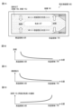
- the heat exchange device disclosed herein can be used to reduce the pressure resistance of a container.
- NS heat exchanger YK container, KR high temperature region, TR low temperature region, ET liquid, YB solvent, YS solute, KO solid, KT gas.
Landscapes
- Engineering & Computer Science (AREA)
- Physics & Mathematics (AREA)
- Thermal Sciences (AREA)
- Mechanical Engineering (AREA)
- General Engineering & Computer Science (AREA)
- Life Sciences & Earth Sciences (AREA)
- Sustainable Development (AREA)
- Physical Or Chemical Processes And Apparatus (AREA)
Priority Applications (4)
| Application Number | Priority Date | Filing Date | Title |
|---|---|---|---|
| PCT/JP2023/002777 WO2024161437A1 (ja) | 2023-01-30 | 2023-01-30 | 熱交換装置及び熱交換方法 |
| JP2024559596A JP7630744B2 (ja) | 2023-01-30 | 2023-01-30 | 熱交換装置及び熱交換方法 |
| DE112023004826.6T DE112023004826T5 (de) | 2023-01-30 | 2023-01-30 | Wärmetauschvorrichtung und wärmeaustauschverfahren |
| US19/186,803 US20250251198A1 (en) | 2023-01-30 | 2025-04-23 | Heat exchange device and heat exchange method |
Applications Claiming Priority (1)
| Application Number | Priority Date | Filing Date | Title |
|---|---|---|---|
| PCT/JP2023/002777 WO2024161437A1 (ja) | 2023-01-30 | 2023-01-30 | 熱交換装置及び熱交換方法 |
Related Child Applications (1)
| Application Number | Title | Priority Date | Filing Date |
|---|---|---|---|
| US19/186,803 Continuation US20250251198A1 (en) | 2023-01-30 | 2025-04-23 | Heat exchange device and heat exchange method |
Publications (1)
| Publication Number | Publication Date |
|---|---|
| WO2024161437A1 true WO2024161437A1 (ja) | 2024-08-08 |
Family
ID=92146024
Family Applications (1)
| Application Number | Title | Priority Date | Filing Date |
|---|---|---|---|
| PCT/JP2023/002777 Ceased WO2024161437A1 (ja) | 2023-01-30 | 2023-01-30 | 熱交換装置及び熱交換方法 |
Country Status (4)
| Country | Link |
|---|---|
| US (1) | US20250251198A1 (https=) |
| JP (1) | JP7630744B2 (https=) |
| DE (1) | DE112023004826T5 (https=) |
| WO (1) | WO2024161437A1 (https=) |
Citations (5)
| Publication number | Priority date | Publication date | Assignee | Title |
|---|---|---|---|---|
| JPS502243A (https=) * | 1973-05-14 | 1975-01-10 | ||
| JPS5659191A (en) * | 1979-10-19 | 1981-05-22 | Hitachi Ltd | Heat pipe |
| JPS576037B2 (https=) * | 1976-02-10 | 1982-02-02 | ||
| US20170074603A1 (en) * | 2014-03-21 | 2017-03-16 | Board Of Regents, The University Of Texas System | Heat pipes with electrical pumping of condensate |
| CN112648871A (zh) * | 2021-01-05 | 2021-04-13 | 大连理工大学 | 一种非均匀润湿性图案化吸液芯超薄平板热管 |
-
2023
- 2023-01-30 JP JP2024559596A patent/JP7630744B2/ja active Active
- 2023-01-30 WO PCT/JP2023/002777 patent/WO2024161437A1/ja not_active Ceased
- 2023-01-30 DE DE112023004826.6T patent/DE112023004826T5/de active Granted
-
2025
- 2025-04-23 US US19/186,803 patent/US20250251198A1/en active Pending
Patent Citations (5)
| Publication number | Priority date | Publication date | Assignee | Title |
|---|---|---|---|---|
| JPS502243A (https=) * | 1973-05-14 | 1975-01-10 | ||
| JPS576037B2 (https=) * | 1976-02-10 | 1982-02-02 | ||
| JPS5659191A (en) * | 1979-10-19 | 1981-05-22 | Hitachi Ltd | Heat pipe |
| US20170074603A1 (en) * | 2014-03-21 | 2017-03-16 | Board Of Regents, The University Of Texas System | Heat pipes with electrical pumping of condensate |
| CN112648871A (zh) * | 2021-01-05 | 2021-04-13 | 大连理工大学 | 一种非均匀润湿性图案化吸液芯超薄平板热管 |
Also Published As
| Publication number | Publication date |
|---|---|
| JP7630744B2 (ja) | 2025-02-17 |
| US20250251198A1 (en) | 2025-08-07 |
| DE112023004826T5 (de) | 2025-09-04 |
| JPWO2024161437A1 (https=) | 2024-08-08 |
Similar Documents
| Publication | Publication Date | Title |
|---|---|---|
| EP0429188A2 (en) | Boiling and condensing heat transfer type cooler device for power semiconductor switching elements | |
| Hihara et al. | Effect of surfactant on falling film absorption | |
| Tiznobaik et al. | Effect of formation of “long range” secondary dendritic nanostructures in molten salt nanofluids on the values of specific heat capacity | |
| Kumar et al. | Aqueous ionic liquid solutions for boiling heat transfer enhancement in the absence of buoyancy induced bubble departure | |
| CN103525373A (zh) | 一种复合定形相变储热材料及其制备方法 | |
| JP7630744B2 (ja) | 熱交換装置及び熱交換方法 | |
| KR20110106942A (ko) | 비등 냉각 장치 | |
| Miloudi et al. | Encapsulation of phase change materials with alginate modified by nanostructured sodium carbonate and silicate | |
| Cao et al. | Self-activated elastocapillary wave promotes boiling heat transfer on soft liquid metal surface | |
| Svitova et al. | Spreading of aqueous dimethyldidodecylammonium bromide surfactant droplets over liquid hydrocarbon substrates | |
| Liu et al. | Photothermal enhanced salinity-gradient osmotic energy conversion for sustainable power generation with phase change material | |
| US11198074B2 (en) | Method for assisting thermally-induced changes | |
| FR2503855A1 (fr) | Echangeur de chaleur a milieu de stockage de chaleur | |
| JP2001336890A (ja) | 伝熱装置 | |
| Wang et al. | Influence of CHF enhancement by different surfactants in TiO₂ and CNTs hybrid nanofluid on a downward heating plane | |
| JPS6022279B2 (ja) | 蓄熱装置 | |
| JP2020041779A (ja) | 蓄熱装置 | |
| TWI752345B (zh) | 具有石墨烯的熱傳增強裝置 | |
| JP2007017115A (ja) | ヒートパイプ | |
| JP4043655B2 (ja) | ヒートパイプ用作動液およびヒートパイプ | |
| JPS61240094A (ja) | ヒ−トパイプ | |
| CN205164762U (zh) | 一种微管稳定沸腾装置 | |
| Barus | Hot water and soft glass in their thermodynamic relations | |
| Hao et al. | Experimental investigation of the electro-de-wetting effect on the regulation of pool boiling behavior | |
| JPS61173085A (ja) | 潜熱蓄熱装置 |
Legal Events
| Date | Code | Title | Description |
|---|---|---|---|
| 121 | Ep: the epo has been informed by wipo that ep was designated in this application |
Ref document number: 23919582 Country of ref document: EP Kind code of ref document: A1 |
|
| WWE | Wipo information: entry into national phase |
Ref document number: 2024559596 Country of ref document: JP |
|
| WWE | Wipo information: entry into national phase |
Ref document number: 112023004826 Country of ref document: DE |
|
| WWP | Wipo information: published in national office |
Ref document number: 112023004826 Country of ref document: DE |
|
| 122 | Ep: pct application non-entry in european phase |
Ref document number: 23919582 Country of ref document: EP Kind code of ref document: A1 |