WO2024157955A1 - 排ガス浄化用触媒、及びこれを用いた排ガス浄化装置 - Google Patents
排ガス浄化用触媒、及びこれを用いた排ガス浄化装置 Download PDFInfo
- Publication number
- WO2024157955A1 WO2024157955A1 PCT/JP2024/001765 JP2024001765W WO2024157955A1 WO 2024157955 A1 WO2024157955 A1 WO 2024157955A1 JP 2024001765 W JP2024001765 W JP 2024001765W WO 2024157955 A1 WO2024157955 A1 WO 2024157955A1
- Authority
- WO
- WIPO (PCT)
- Prior art keywords
- catalyst layer
- catalyst
- exhaust gas
- particles
- alumina
- Prior art date
- Legal status (The legal status is an assumption and is not a legal conclusion. Google has not performed a legal analysis and makes no representation as to the accuracy of the status listed.)
- Ceased
Links
Images


Classifications
-
- B—PERFORMING OPERATIONS; TRANSPORTING
- B01—PHYSICAL OR CHEMICAL PROCESSES OR APPARATUS IN GENERAL
- B01D—SEPARATION
- B01D53/00—Separation of gases or vapours; Recovering vapours of volatile solvents from gases; Chemical or biological purification of waste gases, e.g. engine exhaust gases, smoke, fumes, flue gases, aerosols
- B01D53/34—Chemical or biological purification of waste gases
- B01D53/92—Chemical or biological purification of waste gases of engine exhaust gases
- B01D53/94—Chemical or biological purification of waste gases of engine exhaust gases by catalytic processes
-
- B—PERFORMING OPERATIONS; TRANSPORTING
- B01—PHYSICAL OR CHEMICAL PROCESSES OR APPARATUS IN GENERAL
- B01J—CHEMICAL OR PHYSICAL PROCESSES, e.g. CATALYSIS OR COLLOID CHEMISTRY; THEIR RELEVANT APPARATUS
- B01J23/00—Catalysts comprising metals or metal oxides or hydroxides, not provided for in group B01J21/00
- B01J23/70—Catalysts comprising metals or metal oxides or hydroxides, not provided for in group B01J21/00 of the iron group metals or copper
- B01J23/89—Catalysts comprising metals or metal oxides or hydroxides, not provided for in group B01J21/00 of the iron group metals or copper combined with noble metals
-
- F—MECHANICAL ENGINEERING; LIGHTING; HEATING; WEAPONS; BLASTING
- F01—MACHINES OR ENGINES IN GENERAL; ENGINE PLANTS IN GENERAL; STEAM ENGINES
- F01N—GAS-FLOW SILENCERS OR EXHAUST APPARATUS FOR MACHINES OR ENGINES IN GENERAL; GAS-FLOW SILENCERS OR EXHAUST APPARATUS FOR INTERNAL-COMBUSTION ENGINES
- F01N3/00—Exhaust or silencing apparatus having means for purifying, rendering innocuous, or otherwise treating exhaust
- F01N3/08—Exhaust or silencing apparatus having means for purifying, rendering innocuous, or otherwise treating exhaust for rendering innocuous
- F01N3/10—Exhaust or silencing apparatus having means for purifying, rendering innocuous, or otherwise treating exhaust for rendering innocuous by thermal or catalytic conversion of noxious components of exhaust
-
- Y—GENERAL TAGGING OF NEW TECHNOLOGICAL DEVELOPMENTS; GENERAL TAGGING OF CROSS-SECTIONAL TECHNOLOGIES SPANNING OVER SEVERAL SECTIONS OF THE IPC; TECHNICAL SUBJECTS COVERED BY FORMER USPC CROSS-REFERENCE ART COLLECTIONS [XRACs] AND DIGESTS
- Y02—TECHNOLOGIES OR APPLICATIONS FOR MITIGATION OR ADAPTATION AGAINST CLIMATE CHANGE
- Y02T—CLIMATE CHANGE MITIGATION TECHNOLOGIES RELATED TO TRANSPORTATION
- Y02T10/00—Road transport of goods or passengers
- Y02T10/10—Internal combustion engine [ICE] based vehicles
- Y02T10/12—Improving ICE efficiencies
Definitions
- the present invention relates to an exhaust gas purification catalyst that contains platinum group elements and Ni as catalytically active components, and an exhaust gas purification device that uses the same.
- TWCs three-way catalysts
- PGMs platinum group metals
- Ru ruthenium
- Rh rhodium
- Pr palladium
- Ir osmium
- Ir iridium
- platinum platinum
- a three-way catalyst As a three-way catalyst, a three-way catalyst with a composite particle structure in which catalytically active components are highly dispersed on a base material particle in the form of fine particles is widely used in order to reduce the amount of relatively expensive PGM used while ensuring high catalytic activity.
- Specific examples include three-way catalysts containing composite catalyst particles of base material particles made of metal oxides such as alumina, zirconia, and ceria, and platinum group elements such as Pt and Pd supported on the base material particles.
- catalyst-coated gasoline particulate filters have also entered the practical stage, in which these three-way catalysts are coated as catalytic materials on a wall-flow type honeycomb carrier that functions as a filter to trap particulate matter (PM).
- sulfur content sulfur and sulfur-containing compounds contained in fuel cause an increase in the emission of hydrogen sulfide ( H2S ) and sulfur oxides (SOx), so most of the sulfur content in fuel is removed in advance.
- H2S hydrogen sulfide
- SOx sulfur oxides
- transition metals such as Cu, Ni, Fe, Mn, and Co as catalytically active components.
- these transition metals alone do not have sufficient purification performance for hydrocarbons (HC), carbon monoxide (CO), and nitrogen oxides (NOx), so three-way catalysts that combine PGM with transition metals are being considered.
- Patent Document 1 also describes a catalyst article for purifying exhaust substances, comprising a first catalyst coating containing a platinum group metal, a second catalyst coating containing one or more non-platinum group metals selected from the group consisting of Cu, Ni, Fe, Mn, and Co, and one or more substrates, wherein the first catalyst coating is essentially free of Cu, Ni, Fe, Mn, V, Co, Ga, Mo, Mg, Cr, and Zn, the second catalyst coating is essentially free of platinum group metals, and the first catalyst coating is isolated from the second catalyst coating.
- the catalyst article further includes a barrier layer between the first catalytic coating and the second catalytic coating, the barrier layer including a support selected from stabilized alumina, ceria, zirconia, ceria-zirconia composite, titania, and combinations thereof, the support being stabilized with an element selected from the group consisting of La, Ba, Y, Pr, Sr, and combinations thereof, and the first catalytic coating is on the second catalytic coating or the first catalytic coating is upstream of the second catalytic coating.
- the barrier layer including a support selected from stabilized alumina, ceria, zirconia, ceria-zirconia composite, titania, and combinations thereof, the support being stabilized with an element selected from the group consisting of La, Ba, Y, Pr, Sr, and combinations thereof, and the first catalytic coating is on the second catalytic coating or the first catalytic coating is upstream of the second catalytic coating.
- Patent Document 1 does not consider at all the reduction of NH3 emissions.
- Patent Document 1 discloses that PGM and transition metals are arranged separately in different catalyst layers to remove hydrocarbons, CO, and NOx compounds, but the transition metal is mixed with ceria and alumina as shown in the non-platinum group metal coatings A and B in the examples of Patent Document 1. According to the findings of the present inventors, when the transition metal is mixed with ceria and alumina in this way, when exposed to high temperatures, they may unintentionally react to form an alloy with PGM, form a composite oxide with alumina, or cause sintering of ceria, which may result in a decrease in purification performance for CO, NOx, and NH3 , and it has been found that further improvement is necessary.
- an object of the present invention is to provide an exhaust gas purification catalyst that reduces the generation of sulfur compound smell and has excellent NOx purification performance and NH3 purification performance, and an exhaust gas purification device using the same.
- the inventors conducted extensive research to solve the above problems. As a result, they discovered that the above problems could be solved by providing a catalyst layer with a specific layer structure on a substrate, and thus completed the present invention.
- a catalyst for exhaust gas purification comprising at least a substrate and a catalyst layer provided on the substrate, the catalyst layer having a stacking structure selected from the group consisting of a first stacking structure having a first catalyst layer provided on the substrate, a second catalyst layer provided on the first catalyst layer, and a third catalyst layer provided on the second catalyst layer, and a second stacking structure having a second catalyst layer provided on the substrate, the first catalyst layer provided on the second catalyst layer, and a third catalyst layer provided on the first catalyst layer, the first catalyst layer including at least first base particles and first composite catalyst particles containing a platinum group element supported on the first base particles, the second catalyst layer including at least Ni and alumina particles, and the third catalyst layer including at least third base particles and third composite catalyst particles containing a platinum group element supported on the third base particles.
- An exhaust gas purification device comprising a three-way catalyst arranged downstream of an exhaust gas flow path of a gasoline engine, the three-way catalyst being an exhaust gas purification catalyst described in any one of (1) to (8) above.
- the exhaust gas purification catalyst of the present invention is a three-way catalyst (TWC) that reduces NOx, CO, HC, and the like in exhaust gas, and is a three-way catalyst that is excellent in NH 3 purification rate and reduces generation of sulfur compound smell without causing excessive deterioration of NOx purification performance, and is compatible with next-generation environmental standards.
- TWC three-way catalyst
- FIG. 1 is a schematic diagram showing a schematic configuration of an exhaust gas purifying catalyst 100 according to one embodiment.
- FIG. 2 is a schematic diagram showing a schematic configuration of an exhaust gas purification catalyst 200 according to one embodiment.
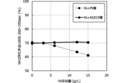
- FIG. 3 is a graph showing the NH 3 purification rates of the exhaust gas purification catalysts of Examples 1 to 4 and Comparative Examples 1 to 6 in the LA4 (FTP75) mode.
- FIG. 4 is a graph showing the NOx purification rates of the exhaust gas purification catalysts of Examples 1 to 4 and Comparative Examples 1 to 6 in the LA4 (FTP75) mode.
- FIG. 5 is a graph showing the NH 3 purification rates of the exhaust gas purifying catalysts of Examples 1 to 4 and Comparative Examples 1 to 6 in the US06 mode.
- D90 particle size refers to the particle size when the cumulative value from the smallest particle size reaches 90% of the total in the cumulative distribution of particle sizes based on volume, and refers to the value measured using a laser diffraction particle size distribution analyzer (for example, the laser diffraction particle size distribution analyzer SALD-3100 manufactured by Shimadzu Corporation).
- the BET specific surface area is the value determined by the BET single point method using a specific surface area/pore distribution analyzer (product name: BELSORP-mini II, manufactured by Microtrac-Bell Co., Ltd.) and analysis software (product name: BEL_Master, manufactured by Microtrac-Bell Co., Ltd.).
- the exhaust gas purification catalyst 100 includes a substrate 11 and a catalyst layer 21 provided on at least one surface 11a of the substrate 11.
- the catalyst layer 21 has a laminated structure including a first catalyst layer L1, a second catalyst layer L2, and a third catalyst layer L3 in this order.
- the first catalyst layer L1 includes at least a first composite catalyst particle containing a platinum group element supported on the first substrate particle and the first composite catalyst particle containing a platinum group element.
- the second catalyst layer L2 includes at least Ni and alumina particles.
- the third catalyst layer L3 includes at least a third composite catalyst particle containing a third substrate particle and the third composite catalyst particle containing a platinum group element supported on the third substrate particle.
- FIG. 2 is a schematic diagram showing the schematic configuration of an exhaust gas purification catalyst 200 according to another preferred embodiment of the present invention.
- the exhaust gas purification catalyst 200 includes a substrate 11 and a catalyst layer 21 provided on at least one surface 11a of the substrate 11.
- the catalyst layer 21 has a laminated structure including a second catalyst layer L2, a first catalyst layer L1, and a third catalyst layer L3 in this order.
- the first catalyst layer L1 includes at least a first composite catalyst particle containing a platinum group element supported on a first base material particle and the first base material particle.
- the second catalyst layer L2 includes at least Ni and alumina particles.
- the third catalyst layer L3 includes at least a third composite catalyst particle containing a third base material particle and the platinum group element supported on the third base material particle.
- the substrate 11 is a support member for supporting the catalyst layer 21.
- the substrate 11 By using the substrate 11 as an integrally structured laminated catalyst member for exhaust gas purification in which the catalyst layer 21 is provided, the substrate 11 can be easily incorporated into an apparatus, and the applicability to various uses is increased.
- a honeycomb structure carrier or the like is used as the substrate 11, and this integrally structured laminated catalyst member is placed in a flow path through which a gas flow passes, and the gas flow is passed through the cells of the honeycomb structure carrier, thereby enabling highly efficient exhaust gas purification.
- the substrate 11 used here can be appropriately selected from those known in the industry.
- Specific examples include monolithic honeycomb carriers known in the industry, such as ceramic monolith carriers made of cordierite, cordierite alumina, silicon carbide, silicon carbide, silicon nitride, etc., metal honeycomb carriers made of stainless steel, wire mesh carriers made of stainless steel, steel wool-like knitted wire carriers, etc., but are not particularly limited to these.
- the shape is also not particularly limited, and any shape can be selected, such as a prismatic, cylindrical, spherical, honeycomb, or sheet shape. These can be used alone or in appropriate combination of two or more types.
- a flow-through type honeycomb carrier having a structure with many through holes (gas flow paths) that open from one open end face to the other open end face
- a wall-flow type honeycomb carrier in which one open end face and the other open end face are alternately sealed and gas can flow through the porous wall surface. Both of these are applicable.
- Flow-through type honeycomb carriers are widely used in oxidation catalysts, reduction catalysts, three-way catalysts (TWC), etc.
- Wall-flow type honeycomb carriers function as filters that filter out solid and particulate components such as soot and SOF in exhaust gas, and are widely used as diesel particulate filters (DPFs), gasoline particulate filters (GPFs), etc.
- the size of the substrate 11 can be appropriately set depending on the application and required performance, and is not particularly limited, but for example, a substrate with a diameter (length) of several millimeters to several centimeters can be used.
- the substrate 11 such as an integral structure type honeycomb carrier, the number of holes in the openings is also set appropriately taking into consideration the type of exhaust gas to be treated, the gas flow rate, pressure loss, removal efficiency, etc.
- the cell density is not particularly limited, but from the viewpoint of maintaining a high contact area (surface area) of the catalyst with the gas flow while maintaining strength and suppressing an increase in pressure loss, the cell density is 100 to 1500 cell/inch 2 (155 k to 2325 k/m 2 ), particularly 200 to 1200 cell/inch 2 (310 k to 1400 k/m 2 ), and more preferably 300 to 900 cell/inch 2 (465 k to 933 k/m 2 ).
- the cell density means the number of cells per unit area in a cross section of the substrate 11 such as an integrally-structured honeycomb carrier cut perpendicularly to the gas flow path.
- the catalyst layer 21 has a first stacked structure including at least the first catalyst layer L1, the second catalyst layer L2, and the third catalyst layer L3 in this order, or a second stacked structure including at least the second catalyst layer L2, the first catalyst layer L1, and the third catalyst layer L3 in this order.
- a catalyst layer containing Ni separately from the catalyst layer containing PGM, it is possible to suppress the deterioration of purification performance due to the combined use of PGM and Ni, and to suppress the diffusion of Ni to the adjacent catalyst layer.
- first catalyst layer L1 the second catalyst layer L2, and the third catalyst layer L3 are arranged in this order, and as long as they are arranged in this order, any other layer (e.g., a primer layer, an adhesive layer, etc.) may be interposed between these layers.
- any other layer e.g., a primer layer, an adhesive layer, etc.
- the stacked structure of the catalyst layer 21 may be any of an embodiment in which the first catalyst layer L1, the second catalyst layer L2, and the third catalyst layer L3 are directly placed on top of each other (first catalyst layer L1/second catalyst layer L2/third catalyst layer L3), or an embodiment in which the first catalyst layer L1, the second catalyst layer L2, and the third catalyst layer L3 are arranged spaced apart with any other layer interposed therebetween (e.g., first catalyst layer L1/other layer/second catalyst layer L2/other layer/third catalyst layer L3, first catalyst layer L1/other layer/second catalyst layer L2/third catalyst layer L3, or first catalyst layer L1/second catalyst layer L2/other layer/third catalyst layer L3).
- "provided on at least one surface of the substrate 11” means that either the catalyst layer 21 is provided only on one surface 11a (or the other surface 11b) of the substrate 11 as shown in FIG. 1, or the catalyst layer 21 is provided on both surfaces 11a, 11b of the substrate 11.
- any other layer e.g., a primer layer, an adhesive layer, etc.
- “provided on one surface” means that either the substrate 11 and the catalyst layer 21 are directly placed on each other, or the substrate 11 and the catalyst layer 21 are spaced apart via any other layer.
- the first catalyst layer L1 includes at least first matrix particles and first composite catalyst particles containing a platinum group element supported on the first matrix particles.
- the first base particles are carrier particles that support a platinum group element, which is a catalytically active component, on the surface in a highly dispersed manner.
- the first base particles can be appropriately selected from those known in the art and are not particularly limited in type.
- aluminum oxides such as ⁇ -alumina, ⁇ -alumina, ⁇ -alumina, ⁇ -alumina, and ⁇ -alumina (alumina: Al 2 O 3 ), silica-alumina, silica-alumina-zirconia, silica-alumina-boria, ceria-alumina, cerium oxide (ceria: CeO 2 ), zirconium oxide (zirconia: ZrO 2 ), ceria-zirconia composite oxide (CZ composite oxide: CeO 2 /ZrO 2 ), silicon oxide (silica: SiO 2 ), and titanium oxide (titania: TiO 2 ) and composite oxides mainly composed of these oxides can be mentioned, but the type is not particularly limited.
- These may be composite oxides or solid solutions to which rare earth elements such as lanthanum and yttrium, transition metal elements, and alkaline earth metal elements have been added.
- Zeolites and analogues such as A, X, Y, MOR, CHA, and SAPO, as well as ⁇ -type and MFI-type zeolites, can also be used.
- These base particles can be used alone or in any combination and ratio of two or more types.
- alumina particles which are heat-resistant inorganic oxides having a high surface area
- ceria-based composite oxide particles which are heat-resistant inorganic oxides having oxygen storage capacity and a high dispersion function for platinum group metals, are preferably used.
- ceria-based composite oxide particles those known in the art can be used, and the type is not particularly limited.
- the term ceria-based composite oxide is used as a concept that includes composite oxides or solid solutions containing cerium (Ce) and doped with elements other than cerium as necessary.
- Ceria-based composite oxides are known as oxygen absorbing and releasing materials with excellent heat resistance.
- the ceria-based composite oxide particles can be used alone or in appropriate combination of two or more types.
- ceria-based composite oxides include cerium composite oxide, cerium-zirconium composite oxide, cerium-zirconium-rare earth element composite oxide excluding cerium and zirconium, cerium-zirconium-transition metal element composite oxide, cerium-aluminum composite oxide, cerium-zirconium-rare earth element-transition metal element composite oxide excluding cerium and zirconium, etc., but are not particularly limited thereto.
- the average particle size of the ceria-based composite oxide particles contained in the first catalyst layer L1 can be set appropriately according to the desired performance, and is not particularly limited, but the D90 particle size is preferably 1 ⁇ m to 30 ⁇ m, more preferably 3 ⁇ m to 25 ⁇ m, and even more preferably 5 ⁇ m to 20 ⁇ m.
- the amount of the ceria-based composite oxide particles applied in the first catalyst layer L1 can be set appropriately according to the desired performance and is not particularly limited, but from the viewpoints of oxygen absorption/release performance, heat resistance, and pressure loss, the total amount of the ceria-based composite oxide particles, converted into solid content, is preferably 5 g/L to 200 g/L, and more preferably 10 g/L to 100 g/L, per unit volume of the substrate 11.
- alumina particles ⁇ -alumina, ⁇ -alumina, ⁇ -alumina, boehmite, etc., which have a large surface area, are preferably used.
- ⁇ -alumina is inferior in durability at 1000°C or higher compared to other aluminas, but has sufficient heat resistance as an exhaust gas purification catalyst that is usually used at 1000°C or lower, and has the largest surface area of all these aluminas. Therefore, ⁇ -alumina is particularly preferable as alumina particles.
- the alumina particles may be a composite oxide or solid solution to which rare earth elements such as zirconium, lanthanum, yttrium, transition metal elements, and alkaline earth metal elements have been added.
- the alumina particles can be used alone or in any combination and ratio of two or more types.
- the average particle size of the alumina particles can be set appropriately depending on the desired performance, and is not particularly limited, but the D90 particle size is preferably 1 ⁇ m to 30 ⁇ m, more preferably 3 ⁇ m to 25 ⁇ m, and even more preferably 5 ⁇ m to 20 ⁇ m.
- the BET specific surface area of the alumina particles is not particularly limited, but from the viewpoint of maintaining a high surface area as the base particles and stably supporting the PGM in a highly dispersed state, it is preferably 30 m 2 /g to 300 m 2 /g, more preferably 40 m 2 /g to 250 m 2 /g, and even more preferably 50 m 2 /g to 200 m 2 /g.
- the amount of alumina particles applied in the first catalyst layer L1 can be set appropriately according to the desired performance and is not particularly limited, but from the viewpoint of heat resistance and pressure loss, the total amount of alumina particles, converted into solid content, per unit volume of the substrate 11 is preferably 5 g/L to 200 g/L, and more preferably 10 g/L to 100 g/L.
- the first base particles contained in the first catalyst layer L1 may contain base particles other than the above-mentioned ceria-based composite oxide particles and alumina particles (hereinafter, may be referred to as "other base particles").
- other base particles those known in the art may be used, and the type is not particularly limited.
- oxides such as silica-alumina, silica-alumina-zirconia, silica-alumina-boria, zirconium oxide (zirconia: ZrO 2 ), silicon oxide (silica: SiO 2 ), titanium oxide (titania: TiO 2 ), etc., and composite oxides mainly composed of these oxides, etc., may be mentioned, but the type is not particularly limited.
- These may be composite oxides or solid solutions to which rare earth elements such as lanthanum and yttrium, transition metal elements, and alkaline earth metal elements are added.
- rare earth elements such as lanthanum and yttrium, transition metal elements, and alkaline earth metal elements are added.
- zeolites such as ⁇ -type and MFI-type zeolites, as well as zeolites such as A, X, Y, MOR, CHA, and SAPO, and their analogues may also be used. These other base particles may be used alone or in any combination and ratio of two or more kinds.
- a platinum group element is essential as a catalytically active component of the first catalyst layer L1.
- the platinum group element is primarily used as a catalytically active component for oxidizing and purifying HC, CO, etc. in exhaust gas, or for oxidizing and converting NOx during fuel-lean operation, and for reducing and purifying NOx during fuel-rich operation.
- the platinum group element may be supported on the first base material particles described above, but may also be supported on other base material particles.
- the platinum group element and other catalytically active components in the first catalyst layer L1 are preferably present as metals (metallic state), but may be partially in the form of oxides depending on the external environment, etc.
- the total content of platinum group elements in the first catalyst layer L1 can be set appropriately according to the desired performance and is not particularly limited, but from the viewpoint of the balance between the oxidation reaction and the reduction reaction, the total content is preferably 0.01 g/L to 15.00 g/L, more preferably 0.05 g/L to 12.00 g/L, and even more preferably 0.10 g/L to 10.00 g/L, in terms of metal (Pt, etc.) per unit volume of the substrate 11.
- platinum group elements include platinum (Pt), palladium (Pd), rhodium (Rh), iridium (Ir), ruthenium (Ru), and osmium (Os).
- Platinum group elements can be used alone or in any combination and ratio of two or more.
- the first catalyst layer L1 may contain only Pt as the platinum group element. It may also contain platinum group elements other than Pt, or it may contain only Pd as the platinum group element.
- Other platinum group elements include palladium (Pd), rhodium (Rh), iridium (Ir), ruthenium (Ru), and osmium (Os).
- the first catalytic layer L1 may also contain catalytically active components other than platinum group elements (hereinafter, these may be referred to as "other catalytically active components").
- catalytically active components include, but are not limited to, precious metal elements such as gold (Au) and silver (Ag), transition metal elements such as iron (Fe), copper (Cu), cobalt (Co), zirconium (Zr), and tungsten (W), and rare earth metal elements such as lanthanum (La), praseodymium (Pr), and neodymium (Nd).
- the first catalytic layer L1 does not substantially contain Ni.
- the first catalyst layer L1 being substantially free of Ni means that the content of Ni contained in the first catalyst layer L1 is less than 1.0 mass% in terms of oxide (NiO) relative to the total amount of the first catalyst layer L1, preferably less than 0.5 mass%, and more preferably less than 0.1 mass%. It is also possible to have an embodiment in which Ni is not intentionally added to the first catalyst layer L1, in which case there is no Ni at all in the first catalyst layer L1 (0.0 mass% in terms of oxide (NiO)).
- the first catalyst layer L1 preferably contains Ba, which has a NOx storage function and a function of improving the heat resistance of the base material.
- the Ba component which is a NOx storage material, stores NOx as barium nitrate in an oxygen-rich (lean) state, and releases the stored NOx when the barium nitrate changes to barium carbonate in an oxygen-poor (rich) state.
- the NOx released in this way is purified by a catalytic reaction with a catalytically active component such as a platinum group element, using the reducing agent HC, CO, or hydrogen generated by a steam reforming reaction.
- the sintering of the base material itself can be suppressed, and the heat resistance of the base material can be improved. Therefore, by including Ba in the first catalyst layer L1, it is expected that the heat resistance can be improved and the catalytic performance can be activated.
- Ba is preferably supported on the above-mentioned ceria composite oxide particles or alumina particles.
- Ba By supporting Ba on the above-mentioned base material particles, Ba itself is maintained in a highly dispersed state, and the heat resistance of the base material particles can be improved.
- Ba on the surface of the first base material particle may be oxidized by exposure to high temperatures during firing or exhaust gas purification in the manufacturing process described below, so it may exist in the form of BaO, which is an oxide, or may exist in the form of various salts such as sulfates, nitrates, carbonates, and acetates depending on the external environment.
- BaO, Ba(CH 3 COO) 2 , BaO 2 , BaSO 4 , BaCO 3 , BaZrO 3 , BaAl 2 O 4 , etc. may be mentioned.
- Ba may also be supported on base material particles other than ceria composite oxide particles or alumina particles.
- the Ba content in the first catalyst layer L1 is preferably 1 to 30 mass%, more preferably 3 to 20 mass%, calculated as an oxide (BaO) relative to the total amount of the first catalyst layer L1.
- the platinum group element particles supported on the surface of the first base material particles in the first catalyst layer L1 can be surrounded by fine particles to reduce the chance of contact between the platinum group element particles.
- fine particles examples include ceria composite oxide particles and fine particles of alumina other than alumina particles, zirconia, silica, silica-alumina, silica-alumina-zirconia, silica-alumina-boria, zeolite, titania, magnesia, tungsten oxide, lanthanum oxide, neodymium oxide, praseodymium oxide, etc., but are not limited to these.
- the fine particles used here are preferably highly heat-resistant and pre-sintered so that they do not move on the base material particles at high temperatures, and from this perspective, rare earth (composite) oxides (rare earth oxides, rare earth composite oxides) and transition metal oxides are preferred.
- the amount of fine particles used to suppress aggregation can be set appropriately according to the amount of platinum group elements used, and is not particularly limited, but is preferably 10 to 300% by mass, and more preferably 20 to 200% by mass, based on the total amount of platinum group elements.
- the first catalyst layer L1 may contain a binder component known in the art, if necessary.
- binder components include various sols such as boehmite, alumina sol, titania sol, silica sol, and zirconia sol, but are not limited to these.
- soluble salts such as aluminum nitrate, aluminum acetate, titanium nitrate, titanium acetate, zirconium nitrate, and zirconium acetate can also be used as binders.
- acids such as acetic acid, nitric acid, hydrochloric acid, and sulfuric acid can also be used as binders.
- the amount of binder used is not particularly limited, and may be any amount that provides sufficient adhesive strength.
- the first catalyst layer L1 may contain catalysts, co-catalysts, and various additives known in the art.
- various additives include dispersion stabilizers such as nonionic surfactants and anionic surfactants, pH adjusters, and viscosity adjusters, but are not limited to these.
- the second catalyst layer L2 contains at least Ni and alumina particles.
- the Ni contained in the second catalyst layer L2 is a catalytically active component that oxidizes sulfur compounds.
- the Ni contained in the second catalyst layer L2 may suppress the generation or decompose NH 3.
- the second catalyst layer L2 must contain alumina particles, which are heat-resistant inorganic oxides having a large surface area.
- the Ni in the second catalyst layer L2 may or may not be supported on alumina particles.
- the second catalyst layer L2 may contain particles other than alumina particles. In this case, the Ni in the second catalyst layer L2 may or may not be supported on other particles.
- the particles in the second catalyst layer L2 are preferably oxide particles that can maintain the catalytically active component Ni highly dispersed on the surface and have high heat resistance.
- the particles in the second catalyst layer L2 can be appropriately selected from those known in the industry, and the type is not particularly limited.
- the particles in the second catalyst layer L2 can be used alone or in combination of two or more types.
- alumina particles those with large surface areas such as ⁇ -alumina, ⁇ -alumina, ⁇ -alumina, and boehmite are preferably used.
- ⁇ -alumina is less durable at 1000°C or higher than other aluminas, but has sufficient heat resistance as an exhaust gas purification catalyst that is normally used at 1000°C or lower, and has the largest surface area of all these aluminas. Therefore, ⁇ -alumina is particularly preferred as alumina particles.
- Alumina particles can be used alone or in any combination and ratio of two or more types.
- the average particle size of the alumina particles can be set appropriately depending on the desired performance, and is not particularly limited, but the D90 particle size is preferably 1 ⁇ m to 30 ⁇ m, more preferably 3 ⁇ m to 25 ⁇ m, and even more preferably 5 ⁇ m to 20 ⁇ m.
- the BET specific surface area of the alumina particles is not particularly limited, but from the viewpoint of maintaining a high surface area and stably supporting Ni in a highly dispersed state, it is preferably 30 m 2 /g to 300 m 2 /g, more preferably 40 m 2 /g to 250 m 2 /g, and even more preferably 50 m 2 /g to 200 m 2 /g.
- the amount of alumina particles applied in the second catalyst layer L2 can be set appropriately according to the desired performance and is not particularly limited, but from the viewpoint of stably supporting Ni in a highly dispersed state, the total amount, calculated as the solid content of the alumina particles, per unit volume of the substrate 11 is preferably 5 g/L to 100 g/L, and more preferably 10 g/L to 80 g/L.
- the ratio of alumina particles and Ni used in the second catalyst layer L2 can be appropriately set depending on the desired performance and is not particularly limited. However, from the viewpoints of suppressing sulfur compound smell, NOx purification performance, NH3 purification performance, etc., the mass ratio of Al2O3 /Ni is preferably 1.0 or more, more preferably 1.2 or more, and even more preferably 1.5 or more.
- the particles contained in the second catalyst layer L2 may include particles other than the above-mentioned alumina particles (hereinafter, these may be referred to as "other particles").
- other particles those known in the art may be used, and the type is not particularly limited.
- oxides such as silica-alumina-zirconia, silica-alumina-boria, zirconium oxide (zirconia: ZrO 2 ), silicon oxide (silica: SiO 2 ), titanium oxide (titania: TiO 2 ), and the like, and composite oxides mainly composed of these oxides, and the like, may be mentioned, but the type is not particularly limited.
- These may be composite oxides or solid solutions to which rare earth elements such as lanthanum and yttrium, transition metal elements, and alkaline earth metal elements are added.
- rare earth elements such as lanthanum and yttrium, transition metal elements, and alkaline earth metal elements are added.
- zeolites such as ⁇ -type and MFI-type zeolites, as well as zeolites and analogues such as A, X, Y, MOR, CHA, and SAPO, may also be used. These other particles may be used alone or in any combination and ratio of two or more kinds.
- the second catalyst layer L2 may contain a binder component known in the art, if necessary.
- binder components include various sols such as boehmite, alumina sol, titania sol, silica sol, and zirconia sol, but are not limited to these.
- Soluble salts such as aluminum nitrate, aluminum acetate, titanium nitrate, titanium acetate, zirconium nitrate, and zirconium acetate can also be used as binders.
- acids such as acetic acid, nitric acid, hydrochloric acid, and sulfuric acid can also be used as binders.
- the amount of binder used is not particularly limited, and may be any amount that provides sufficient adhesive strength.
- Ni is essential as a catalytically active component of the second catalyst layer L2.
- Ni is mainly used as a catalytically active component that oxidizes sulfur compounds. It is preferable that Ni and other catalytically active components in the second catalyst layer L2 exist as metals (metallic state), but some of them may be in the form of oxides depending on the external environment, etc.
- the total content of Ni in the second catalytic layer L2 can be appropriately set depending on the desired performance and is not particularly limited. From the viewpoint of the balance between the performance for oxidizing sulfur compounds and the performance for purifying NH3 , the total content of Ni in the second catalytic layer L2 is preferably 0.1 g/L to 30.0 g/L, more preferably 0.5 g/L to 25.0 g/L, even more preferably 1.0 g/L to 20.0 g/L, and particularly preferably 2.0 g/L to 20.0 g/L, in terms of oxide (NiO), per unit volume of the substrate 11.
- the second catalyst layer L2 may contain catalytically active components other than Ni.
- catalytically active components include, but are not limited to, precious metal elements such as gold (Au) and silver (Ag), transition metal elements such as iron (Fe), copper (Cu), cobalt (Co), zirconium (Zr), and tungsten (W), and rare earth metal elements such as lanthanum (La), praseodymium (Pr), and neodymium (Nd).
- the second catalyst layer L2 does not substantially contain platinum group elements.
- the second catalyst layer L2 being substantially free of platinum group elements means that the content of platinum group elements contained in the second catalyst layer L2 is less than 1.0 mass% in terms of metal relative to the total amount of the second catalyst layer L2, preferably less than 0.5 mass%, and more preferably less than 0.1 mass%. It is also possible to adopt an embodiment in which platinum group elements are not intentionally added to the second catalyst layer L2, in which case there is no platinum group element at all (0.0 mass%) in the second catalyst layer L2.
- the second catalyst layer L2 may contain catalysts, co-catalysts, and various additives known in the art.
- various additives include dispersion stabilizers such as nonionic surfactants and anionic surfactants, pH adjusters, and viscosity adjusters, but are not limited to these.
- the third catalyst layer L3 includes at least third matrix particles and third composite catalyst particles containing at least a platinum group element supported on the third matrix particles.
- the third base particles are carrier particles that support the platinum group element, which is a catalytically active component, on the surface in a highly dispersed manner.
- the third base particles can be appropriately selected from those known in the art and are not particularly limited in type.
- aluminum oxide alumina: Al 2 O 3
- ceria-alumina cerium oxide (ceria: CeO 2 ), zirconium oxide (zirconia: ZrO 2 ), ceria-zirconia composite oxide (CZ composite oxide: CeO 2 /ZrO 2 ), silicon oxide (silica: SiO 2 ), titanium oxide (titania: TiO 2 ), and other oxides and composite oxides mainly composed of these oxides are listed, but the type is not particularly limited.
- These may be composite oxides or solid solutions to which rare earth elements such as lanthanum and yttrium, transition metal elements, and alkaline earth metal elements have been added.
- Zeolites and analogues such as ⁇ -type and MFI-type zeolites, as well as A, X, Y, MOR, CHA, and SAPO, can also be used.
- These base particles can be used alone or in any combination and ratio of two or more types.
- ceria-zirconia composite oxide particles which are heat-resistant inorganic oxides having oxygen storage capacity
- alumina particles which are heat-resistant inorganic oxides having a high surface area
- the ceria-zirconia-based composite oxide particles those known in the art can be used, and the type is not particularly limited.
- the ceria-zirconia-based composite oxide is used as a concept that includes composite oxides or solid solutions containing cerium (Ce) and zirconium (Zr) and doped with elements other than cerium and zirconium as necessary.
- Ceria-zirconia-based composite oxides are known as oxygen absorbing and releasing materials with excellent heat resistance.
- the ceria-zirconia-based composite oxide particles can be used alone or in appropriate combination of two or more types.
- ceria-zirconia-based composite oxides include cerium-zirconium composite oxides, cerium-zirconium-rare earth element composite oxides excluding cerium and zirconium, cerium-zirconium-transition metal element composite oxides, aluminum-cerium-zirconium composite oxides, cerium-zirconium-rare earth element-transition metal element composite oxides excluding cerium and zirconium, etc., but are not particularly limited thereto.
- the average particle size of the ceria-zirconia composite oxide particles can be set appropriately depending on the desired performance, and is not particularly limited, but the D90 particle size is preferably 1 ⁇ m to 30 ⁇ m, more preferably 3 ⁇ m to 25 ⁇ m, and even more preferably 5 ⁇ m to 20 ⁇ m.
- the amount of the ceria-zirconia-based composite oxide particles applied in the third catalyst layer L3 can be appropriately set according to the desired performance and is not particularly limited, but from the viewpoints of oxygen absorption/release performance, heat resistance, and pressure loss, the total amount of the ceria-zirconia-based composite oxide particles, converted into solid content, is preferably 5 g/L to 80 g/L, and more preferably 10 g/L to 60 g/L, per unit volume of the substrate 11.
- alumina particles ⁇ -alumina, ⁇ -alumina, ⁇ -alumina, boehmite, etc., which have a large surface area, are preferably used.
- ⁇ -alumina is inferior in durability at 1000°C or higher compared to other aluminas, but has sufficient heat resistance as an exhaust gas purification catalyst that is usually used at 1000°C or lower, and has the largest surface area of all these aluminas. Therefore, ⁇ -alumina is particularly preferable as alumina particles.
- the alumina particles may be a composite oxide or solid solution to which rare earth elements such as zirconium, lanthanum, yttrium, transition metal elements, and alkaline earth metal elements have been added.
- the alumina particles can be used alone or in any combination and ratio of two or more types.
- the average particle size of the alumina particles can be set appropriately depending on the desired performance, and is not particularly limited, but the D90 particle size is preferably 1 ⁇ m to 30 ⁇ m, more preferably 3 ⁇ m to 25 ⁇ m, and even more preferably 5 ⁇ m to 20 ⁇ m.
- the BET specific surface area of the alumina particles is not particularly limited, but from the viewpoint of maintaining a high surface area as the base particles and stably supporting the PGM in a highly dispersed state, it is preferably 30 m 2 /g to 300 m 2 /g, more preferably 40 m 2 /g to 250 m 2 /g, and even more preferably 50 m 2 /g to 200 m 2 /g.
- the amount of alumina particles applied in the third catalyst layer L3 can be set appropriately according to the desired performance and is not particularly limited, but from the viewpoint of heat resistance and pressure loss, the total amount of alumina particles, converted into solid content, per unit volume of the substrate 11 is preferably 5 g/L to 80 g/L, and more preferably 10 g/L to 60 g/L.
- the third base particles contained in the third catalyst layer L3 may contain base particles other than the above-mentioned ceria-zirconia composite oxide particles and alumina particles (hereinafter, may be referred to as "other base particles").
- other base particles those known in the art may be used, and the type is not particularly limited.
- oxides such as silica-alumina, silica-alumina-zirconia, silica-alumina-boria, cerium oxide (ceria: CeO 2 ), zirconium oxide (zirconia: ZrO 2 ), silicon oxide (silica: SiO 2 ), titanium oxide (titania: TiO 2 ), etc., and composite oxides mainly composed of these oxides, etc., are listed, but the type is not particularly limited. These may be composite oxides or solid solutions to which rare earth elements such as lanthanum and yttrium, transition metal elements, and alkaline earth metal elements are added.
- rare earth elements such as lanthanum and yttrium, transition metal elements, and alkaline earth metal elements are added.
- base particles may also be used, such as ⁇ -type or MFI-type zeolites, as well as zeolites and their analogues, such as A, X, Y, MOR, CHA, SAPO, etc. These other base particles may be used alone or in any combination and ratio of two or more types.
- the platinum group elements are essential catalytically active components of the third catalyst layer L3.
- platinum group elements include platinum (Pt), palladium (Pd), rhodium (Rh), iridium (Ir), ruthenium (Ru), and osmium (Os).
- the platinum group elements can be used alone or in any combination and ratio of two or more.
- Pt and Rh are primarily used as catalytically active components for oxidizing and purifying HC and CO in exhaust gas, or for oxidizing and converting NOx during lean fuel operation, and for reducing and purifying NOx during excess fuel operation.
- the third catalyst layer L3 may contain only Rh as a platinum group element, or may contain platinum group elements other than Rh.
- the third catalyst layer L3 may contain Rh and Pt.
- Pt and Rh may be supported on the above-mentioned third base material particles, but from the viewpoint of purification performance, Pt is preferably supported on ceria-zirconia composite oxide particles, and Rh is preferably supported on alumina particles.
- the platinum group element may also be supported on other base material particles.
- the platinum group element and other catalytically active components in the third catalyst layer L3 are preferably present as metals (metallic state), but a part of them may be in the form of oxides depending on the external environment, etc.
- the total content of Pt in the third catalyst layer L3 can be set appropriately according to the desired performance and is not particularly limited, but from the viewpoint of the balance between the oxidation reaction and the reduction reaction, the total content of Pt, calculated as metal (Pt), is preferably 0.01 g/L to 15.00 g/L per unit volume of the substrate 11, more preferably 0.05 g/L to 12.00 g/L, and even more preferably 0.10 g/L to 10.00 g/L.
- the total content of Rh in the third catalyst layer L3 can be set appropriately according to the desired performance and is not particularly limited, but from the viewpoint of the balance between the oxidation reaction and the reduction reaction, the total content of Rh in metal (Rh) equivalent is preferably 0.01 g/L to 5.00 g/L per unit volume of the substrate 11, more preferably 0.03 g/L to 4.00 g/L, and even more preferably 0.05 g/L to 3.00 g/L.
- the third catalyst layer L3 may contain only Pt and Rh as platinum group elements, or may contain platinum group elements other than Pt and Rh. Examples of other platinum group elements include palladium (Pd), iridium (Ir), ruthenium (Ru), and osmium (Os).
- the third catalyst layer L3 may also contain catalytically active components other than platinum group elements (hereinafter, these may be referred to as "other catalytically active components").
- catalytically active components examples include precious metal elements such as gold (Au) and silver (Ag), transition metal elements such as iron (Fe), copper (Cu), cobalt (Co), zirconium (Zr), and tungsten (W), and rare earth metal elements such as lanthanum (La), praseodymium (Pr), and neodymium (Nd), but are not limited to these.
- precious metal elements such as gold (Au) and silver (Ag)
- transition metal elements such as iron (Fe), copper (Cu), cobalt (Co), zirconium (Zr), and tungsten (W)
- rare earth metal elements such as lanthanum (La), praseodymium (Pr), and neodymium (Nd), but are not limited to these.
- the third catalyst layer L3 does not substantially contain Ni.
- the third catalyst layer L3 does not substantially contain Ni means that the content of Ni contained in the third catalyst layer L3 is less than 1.0 mass% in oxide equivalent (NiO) with respect to the total amount of the third catalyst layer L3, preferably less than 0.5 mass%, and more preferably less than 0.1 mass%. It is also possible to adopt an embodiment in which Ni is not intentionally added to the third catalyst layer L3, in which case there is no Ni at all in the third catalyst layer L3 (0.0 mass% in oxide equivalent (NiO)).
- the third catalyst layer L3 may contain a binder component known in the art, if necessary.
- binder components include various sols such as boehmite, alumina sol, titania sol, silica sol, and zirconia sol, but are not limited to these.
- Soluble salts such as aluminum nitrate, aluminum acetate, titanium nitrate, titanium acetate, zirconium nitrate, and zirconium acetate can also be used as binders.
- acids such as acetic acid, nitric acid, hydrochloric acid, and sulfuric acid can also be used as binders.
- the amount of binder used is not particularly limited, and may be any amount that provides sufficient adhesive strength.
- the third catalyst layer L3 may contain catalysts, co-catalysts, and various additives known in the art.
- various additives include dispersion stabilizers such as nonionic surfactants and anionic surfactants, pH adjusters, and viscosity adjusters, but are not limited to these.
- the catalyst layer of the exhaust gas purification catalyst 100, 200 of this embodiment has a first stacked structure in which the first catalyst layer L1, the second catalyst layer L2, and the third catalyst layer L3 are stacked in this order, or a 21st stacked structure in which the second catalyst layer L2, the first catalyst layer L1, and the third catalyst layer L3 are stacked in this order.
- it was considered to use a transition metal together with PGM in order to reduce the emission of NH 3 but since the transition metal is a catalyst poison for the catalyst material containing PGM, simply using the transition metal together with PGM causes deterioration of NOx purification performance, etc.
- the catalyst layer containing Ni and alumina particles is provided, which can suppress the generation of sulfur compound smell caused by the very small amount of sulfur that may be contained in the fuel. This not only provides excellent catalytic performance as a three-way catalyst, but also provides an excellent NH3 purification rate and reduces the generation of sulfur compound smell.
- the exhaust gas purification catalysts 100, 200 of this embodiment have a laminated structure of the first catalyst layer L1, the second catalyst layer L2, and the third catalyst layer L3 as the smallest catalyst composition unit, and such a layer structure is desirable not only in terms of work efficiency but also in terms of cost.
- the first catalyst layer L1, the second catalyst layer L2, and the third catalyst layer L3 may be coated (zone coated) only on a portion of the substrate 11.
- the exhaust gas purification catalyst 100, 200 having the above-mentioned layer structure can be manufactured by a method known in the art, and the manufacturing method is not particularly limited. For example, it can be manufactured by sequentially providing each catalyst layer L1, L2, L3 in a predetermined arrangement on a substrate 11 such as the above-mentioned ceramic monolith carrier according to a conventional method. For example, the surface of the substrate 11 is sequentially coated with a slurry mixture of water or an aqueous medium for each catalyst layer L1, L2, L3, to obtain the exhaust gas purification catalyst 100, 200 of this embodiment.
- the method of applying the slurry mixture to the substrate 11 may be performed according to a conventional method, and is not particularly limited. Various known coating methods, wash coat methods, and zone coat methods can be applied.
- Coating by wash coat or the like can be repeated two or more times.
- coating before the drying process may be repeated two or more times, and the drying process may be repeated two or more times.
- drying and firing can be performed according to conventional methods.
- the drying temperature is not particularly limited, but is preferably 50 to 250°C, and more preferably 80 to 230°C.
- the baking temperature is not particularly limited, but is preferably 300 to 700°C, and more preferably 400 to 600°C.
- the heating means used in this step is not particularly limited, but can be any known heating means such as an electric furnace or gas furnace.
- the amount of water or aqueous medium used when preparing the slurry mixture should be sufficient to uniformly disperse each component in the slurry. If necessary, an acid or base can be added to adjust the pH, or a dispersant, surfactant, or dispersion resin can be added to adjust the viscosity or improve dispersibility.
- the slurry can be mixed using any known grinding or mixing method, such as grinding and mixing using a ball mill.
- a dry or wet grinding process, mixing process, or dispersion process can be performed using a ball mill, bead mill, or the like, for the purpose of uniformly dispersing or obtaining the desired particle size.
- the conditions for these processes can be appropriately set according to the desired performance and are not particularly limited, but for example, the D90 particle size of the alumina particles carrying the necessary components can be preferably 1 ⁇ m to 30 ⁇ m, more preferably 2 ⁇ m to 25 ⁇ m, and even more preferably 3 ⁇ m to 20 ⁇ m.
- the total coating amount of the first catalyst layer L1, the second catalyst layer L2, and the third catalyst layer L3 (excluding the platinum group elements contained in each catalyst layer L1, L2, and L3) can be set appropriately according to the desired performance and is not particularly limited, but from the viewpoint of catalyst performance, cost, etc., it is preferably 100 g/L or more and 500 g/L or less in total, 150 g/L or more and 400 g/L or less in total, and more preferably 180 g/L or more and 300 g/L or less in total per volume of the substrate 11.
- the exhaust gas purification catalyst 100, 200 of this embodiment can be used in an integrated exhaust gas purification device and exhaust gas purification system that includes one or more additional components for treating exhaust gas emissions.
- it is useful as an exhaust gas purification catalyst for internal combustion engines such as gasoline engines, particularly as a three-way catalyst for purifying exhaust gas in automobiles.
- the exhaust gas purification catalyst 100, 200 of this embodiment can be arranged in the exhaust system of various engines.
- the number and locations of the catalysts can be appropriately designed according to exhaust gas regulations. For example, when exhaust gas regulations are strict, the number of catalysts to be installed can be two or more, and the installation locations can be located under the floor behind the catalyst directly below the exhaust system. In either case, the catalysts may be arranged adjacent to each other or spaced apart.
- BET specific surface area 150 m 2 /g, average particle diameter D 90 50 ⁇ m
- the obtained slurry mixture for the first catalyst layer L1 was applied to a honeycomb flow-through type cordierite carrier, which was the substrate 11, by a washcoat method, and then dried at 200°C for 30 minutes. Thereafter, the mixture was fired at 500°C for 1 hour in an air atmosphere, thereby forming a first catalyst layer L1 (coating amount: per unit volume of substrate 11, Pt: 0.6 g/L, components of the first catalyst layer excluding Pt: 130 g/L) on the substrate 11.
- the obtained slurry mixture for the second catalyst layer L2 was applied by a washcoat method onto the first catalyst layer L1 of the substrate 11 on which the first catalyst layer L1 had been formed, and then dried at 200° C. for 30 minutes. Thereafter, the mixture was baked at 500° C. for 1 hour in an atmospheric air to form a second catalyst layer L2 (coating amount: per unit volume of substrate 11, Ni: 3.0 g/L, components of the second catalyst layer containing Ni: 40 g/L) on the first catalyst layer L1.
- 50 parts by mass of the obtained Pt-supported ceria-zirconia-based composite oxide particles and 50 parts by mass of Rh-supported alumina particles were mixed, diluted with pure water, and kneaded by a wet milling method to obtain a slurry mixture for the third catalyst layer L3.
- the obtained slurry mixture for the third catalyst layer L3 was applied by a wash coat method onto the second catalyst layer L2 of the substrate 11 on which the first catalyst layer L1 and the second catalyst layer L2 were formed, and then dried at 200° C. for 30 minutes. Thereafter, the mixture was baked at 500° C. for 1 hour in an atmospheric air to form a third catalyst layer L3 (coating amount: per unit volume of substrate 11, Pt: 0.3 g/L, Rh: 0.1 g/L, components of the third catalyst layer excluding Pt and Rh: 80 g/L) on the second catalyst layer L2.
- the exhaust gas purification catalyst of Example 1 was obtained, in which the first catalyst layer L1, the second catalyst layer L2, and the third catalyst layer L3 were provided in this order on the substrate 11, and the catalyst layer had a three-layer structure.
- Examples 2 to 4 and Comparative Example 1 The same procedure as in Example 1 was carried out except that the Ni content was changed as shown in Table 2, to obtain exhaust gas purifying catalysts of Examples 2 to 4 and Comparative Example 1.
- Comparative Example 2 The same procedure as in Example 1 was carried out except that the formation of the second catalyst layer L2 was omitted. In this way, an exhaust gas purifying catalyst of Comparative Example 2 was obtained, in which the first catalyst layer L1 and the third catalyst layer L3 were provided in this order on the substrate 11, and the catalyst layer had a two-layer structure.
- Example 3 A control slurry mixture for the first catalyst layer L1 was obtained in the same manner as in Example 1, except that the first base particles and the nickel oxide powder were mixed when the first catalyst layer L1 was formed. The same procedure as in Example 1 was repeated, except that the above control slurry mixture was used instead of the slurry mixture for the first catalyst layer L1, and further the formation of the second catalyst layer L2 was omitted. In this way, an exhaust gas purifying catalyst of Comparative Example 3 was obtained, in which the first catalyst layer L1 and the third catalyst layer L3 were provided in this order on the substrate 11, and the catalyst layer had a two-layer structure.
- Example 5 The same procedure as in Example 3 was performed except that the order of forming the catalyst layers was changed to the second catalyst layer L2, the first catalyst layer L1, and the third catalyst layer L3, and an exhaust gas purifying catalyst of Example 5 was obtained in which the catalyst layers had a three-layer structure in which the second catalyst layer L2, the first catalyst layer L1, and the third catalyst layer L3 were provided in this order on the substrate 11.
- each of the obtained exhaust gas purification catalysts TWC2 was individually stored in a converter. Then, an integrally structured laminated catalyst having a three-layered catalyst layer described in the examples of Japanese Patent No. 7026530 was arranged as TWC1 downstream of the exhaust port of the gasoline engine, and TWC2 was arranged further downstream of the exhaust port of the gasoline engine, downstream of TWC1. Then, a cycle of steady state, deceleration, and acceleration was repeated for 100 hours. The temperature was set so that the front-stage TWC1 was 950°C at steady state, and a thermal durability treatment was performed. After the above heat treatment, a poisoning treatment was performed.
- the NH 3 purification rate was measured using the exhaust gas purification catalysts after durability treatment and poisoning treatment.
- a 1.5L direct injection turbo engine was used, and TWC1 was arranged downstream of the exhaust port of the gasoline engine as described above, and TWC2 was arranged downstream of TWC1, and measurements were performed in accordance with LA4 (FTP75) mode (cold start) and US06 mode (hot start).
- LA4 FTP75
- US06 mode hot start
- gas analysis was performed by sampling the inlet gas (exhaust gas of TWC1) of the exhaust gas purification catalyst TWC2 and the exhaust gas of TWC2, and the NH 3 purification rate of TWC2 in the entire LA4 mode and the NH 3 purification rate of TWC2 in the 200 to 350 sec section of US06 mode were calculated from the difference.
- the analyzer used was an FT-IR made by Iwata Denko Co., Ltd., and the temperature was measured at a position 1 inch from the front side of the exhaust gas purification catalyst within the catalyst layer.
- the NOx purification rate was measured using the exhaust gas purification catalysts after durability treatment and poisoning treatment.
- a 1.5L direct injection turbo engine was used, and TWC1 was arranged downstream of the exhaust port of the gasoline engine as described above, and TWC2 was arranged downstream of TWC1, and measurements were performed in accordance with the LA4 (FTP75) mode (cold start).
- LA4 FTP75
- an evaluation was performed using an engine dynamometer using a 1.5L gasoline engine in which an exhaust gas purification catalyst was arranged directly under the engine.
- the inlet gas of the exhaust gas purification catalyst TWC2 (the exhaust gas of TWC1) and the exhaust gas of TWC2 were sampled and gas analysis was performed, and the LA4 mode full-range NOx purification rate of TWC2 was calculated from the difference.
- a MEXA-ONE manufactured by HORIBA was used as an analyzer, and the temperature measurement position was set to within the catalyst layer 1 inch from the front side of the exhaust gas purification catalyst.
- the sulfur compound smell was measured using Fresh exhaust gas purification catalyst TWC2 that had not been subjected to durability treatment or poisoning treatment.
- a test of adsorption and desorption of S components was carried out using a tubular furnace and a temperature-programmed desorption apparatus.
- a predetermined amount of S components was circulated through the catalyst using a tubular furnace, and the S components were adsorbed onto the catalyst.
- the catalyst with the S components adsorbed thereon was crushed in a mortar or the like, set in a temperature-programmed desorption apparatus (TPD Type-R), and heated under a reducing gas atmosphere, and the desorbed sulfur-containing gas component H 2 S was detected by a mass spectrometer.
- TPD Type-R temperature-programmed desorption apparatus
- the test conditions at this time are shown in Table 1.
- the exhaust gas purification catalyst of the present invention can be widely and effectively used as a three-way catalyst that reduces NOx, CO, HC, etc. in exhaust gas, and can be particularly effectively used in catalytic applications for purifying exhaust gas from internal combustion engines such as gasoline engines.
- the exhaust gas purification catalyst of the present invention can be effectively used as a TWC such as an engine direct-downstream catalytic converter or a tandem-arranged direct-downstream catalytic converter.
- Exhaust gas purification catalyst 200 Exhaust gas purification catalyst 11: Substrate 11a: Surface 11b: Surface 21: Catalyst layer L1: First catalyst layer L2: Second catalyst layer L3: Third catalyst layer
Landscapes
- Chemical & Material Sciences (AREA)
- Engineering & Computer Science (AREA)
- Chemical Kinetics & Catalysis (AREA)
- Health & Medical Sciences (AREA)
- Combustion & Propulsion (AREA)
- Mechanical Engineering (AREA)
- Toxicology (AREA)
- Organic Chemistry (AREA)
- Materials Engineering (AREA)
- General Engineering & Computer Science (AREA)
- Biomedical Technology (AREA)
- Environmental & Geological Engineering (AREA)
- Analytical Chemistry (AREA)
- General Chemical & Material Sciences (AREA)
- Oil, Petroleum & Natural Gas (AREA)
- Catalysts (AREA)
Priority Applications (1)
| Application Number | Priority Date | Filing Date | Title |
|---|---|---|---|
| JP2024573059A JPWO2024157955A1 (https=) | 2023-01-23 | 2024-01-23 |
Applications Claiming Priority (2)
| Application Number | Priority Date | Filing Date | Title |
|---|---|---|---|
| JP2023-008312 | 2023-01-23 | ||
| JP2023008312 | 2023-01-23 |
Publications (1)
| Publication Number | Publication Date |
|---|---|
| WO2024157955A1 true WO2024157955A1 (ja) | 2024-08-02 |
Family
ID=91970633
Family Applications (1)
| Application Number | Title | Priority Date | Filing Date |
|---|---|---|---|
| PCT/JP2024/001765 Ceased WO2024157955A1 (ja) | 2023-01-23 | 2024-01-23 | 排ガス浄化用触媒、及びこれを用いた排ガス浄化装置 |
Country Status (2)
| Country | Link |
|---|---|
| JP (1) | JPWO2024157955A1 (https=) |
| WO (1) | WO2024157955A1 (https=) |
Citations (4)
| Publication number | Priority date | Publication date | Assignee | Title |
|---|---|---|---|---|
| JPH08290063A (ja) * | 1995-02-24 | 1996-11-05 | Mazda Motor Corp | 排気ガス浄化用触媒及びその製造方法 |
| WO2010001765A1 (ja) * | 2008-07-04 | 2010-01-07 | 日産自動車株式会社 | 排気ガス浄化用触媒 |
| JP2022514767A (ja) * | 2018-12-19 | 2022-02-15 | ビーエーエスエフ コーポレーション | 触媒物品ならびにそれを製造および使用する方法 |
| JP2022514770A (ja) * | 2018-12-19 | 2022-02-15 | ビーエーエスエフ コーポレーション | 層状触媒組成物および触媒物品ならびにそれらを製造および使用する方法 |
-
2024
- 2024-01-23 JP JP2024573059A patent/JPWO2024157955A1/ja active Pending
- 2024-01-23 WO PCT/JP2024/001765 patent/WO2024157955A1/ja not_active Ceased
Patent Citations (4)
| Publication number | Priority date | Publication date | Assignee | Title |
|---|---|---|---|---|
| JPH08290063A (ja) * | 1995-02-24 | 1996-11-05 | Mazda Motor Corp | 排気ガス浄化用触媒及びその製造方法 |
| WO2010001765A1 (ja) * | 2008-07-04 | 2010-01-07 | 日産自動車株式会社 | 排気ガス浄化用触媒 |
| JP2022514767A (ja) * | 2018-12-19 | 2022-02-15 | ビーエーエスエフ コーポレーション | 触媒物品ならびにそれを製造および使用する方法 |
| JP2022514770A (ja) * | 2018-12-19 | 2022-02-15 | ビーエーエスエフ コーポレーション | 層状触媒組成物および触媒物品ならびにそれらを製造および使用する方法 |
Also Published As
| Publication number | Publication date |
|---|---|
| JPWO2024157955A1 (https=) | 2024-08-02 |
Similar Documents
| Publication | Publication Date | Title |
|---|---|---|
| JP7497358B2 (ja) | 層状三元変換(twc)触媒およびその触媒を製造する方法 | |
| US10512898B2 (en) | Layered automotive catalyst composites | |
| CN113574255B (zh) | 层状三金属催化制品和制造所述催化制品的方法 | |
| CN102083531B (zh) | 净化废气的催化剂装置和净化废气的方法 | |
| JP2023539757A (ja) | 白金族金属及び卑金属酸化物を含む酸化触媒 | |
| US20220193639A1 (en) | Layered tri-metallic catalytic article and method of manufacturing the catalytic article | |
| US12179186B2 (en) | Layered catalysts composition and catalytic article and methods of manufacturing and using the same | |
| JP6748590B2 (ja) | 排ガス浄化用触媒 | |
| CN113677433A (zh) | 基于金属氧化物纳米颗粒的催化剂和其制造和使用方法 | |
| CN113905816A (zh) | 催化制品和制造催化制品的方法 | |
| JP7344815B2 (ja) | ガソリンリーンバーンエンジン用lnt積層触媒、及びこれを用いた排ガス浄化装置 | |
| US20220212169A1 (en) | Automotive 3-way catalyst system containing a tail pipe catalyst | |
| JPWO2018147408A1 (ja) | 排ガス用浄化触媒組成物及びその製造方法、並びに自動車用排ガス浄化触媒 | |
| US20240424445A1 (en) | Zoned three-way conversion catalysts comprising platinum, palladium, and rhodium | |
| JP7711046B2 (ja) | ディーゼル酸化触媒 | |
| KR102843951B1 (ko) | 조정 가능한 NOx 흡착제 | |
| WO2024157955A1 (ja) | 排ガス浄化用触媒、及びこれを用いた排ガス浄化装置 | |
| JP2024104200A (ja) | 排ガス浄化用触媒、及びこれを用いた排ガス浄化装置 | |
| WO2023047185A1 (ja) | 排ガス浄化触媒、及びこれを用いた車両用排ガス浄化触媒装置 | |
| CN116764623A (zh) | 排气净化用催化剂 |
Legal Events
| Date | Code | Title | Description |
|---|---|---|---|
| 121 | Ep: the epo has been informed by wipo that ep was designated in this application |
Ref document number: 24747282 Country of ref document: EP Kind code of ref document: A1 |
|
| WWE | Wipo information: entry into national phase |
Ref document number: 2024573059 Country of ref document: JP |
|
| NENP | Non-entry into the national phase |
Ref country code: DE |
|
| 122 | Ep: pct application non-entry in european phase |
Ref document number: 24747282 Country of ref document: EP Kind code of ref document: A1 |