WO2024157903A1 - フローサイトメータ - Google Patents
フローサイトメータ Download PDFInfo
- Publication number
- WO2024157903A1 WO2024157903A1 PCT/JP2024/001530 JP2024001530W WO2024157903A1 WO 2024157903 A1 WO2024157903 A1 WO 2024157903A1 JP 2024001530 W JP2024001530 W JP 2024001530W WO 2024157903 A1 WO2024157903 A1 WO 2024157903A1
- Authority
- WO
- WIPO (PCT)
- Prior art keywords
- light
- bright spot
- illumination
- spot pattern
- optical system
- Prior art date
- Legal status (The legal status is an assumption and is not a legal conclusion. Google has not performed a legal analysis and makes no representation as to the accuracy of the status listed.)
- Ceased
Links
Images




Classifications
-
- G—PHYSICS
- G01—MEASURING; TESTING
- G01N—INVESTIGATING OR ANALYSING MATERIALS BY DETERMINING THEIR CHEMICAL OR PHYSICAL PROPERTIES
- G01N21/00—Investigating or analysing materials by the use of optical means, i.e. using sub-millimetre waves, infrared, visible or ultraviolet light
- G01N21/17—Systems in which incident light is modified in accordance with the properties of the material investigated
- G01N21/47—Scattering, i.e. diffuse reflection
- G01N21/49—Scattering, i.e. diffuse reflection within a body or fluid
- G01N21/53—Scattering, i.e. diffuse reflection within a body or fluid within a flowing fluid, e.g. smoke
Definitions
- the present invention relates to a flow cytometer.
- This application claims priority to U.S. Provisional Application No. 63/440,920, filed January 25, 2023, the contents of which are incorporated herein by reference.
- GMI Global Motion Imaging
- illumination from a light source is processed into illumination light having a specific illumination pattern by a spatial light modulation element such as a DOE (Diffractive Optical Element) installed in the optical path between the light source and the object being observed, and this illumination light is irradiated onto the object being observed moving in the flow path, thereby extracting morphological information of the object being observed as optical information.
- a spatial light modulation element such as a DOE (Diffractive Optical Element) installed in the optical path between the light source and the object being observed
- this illumination light is irradiated onto the object being observed moving in the flow path, thereby extracting morphological information of the object being observed as optical information.
- Patent Document 1 describes a measurement method that extracts morphological information of the object being observed as optical information based on the GMI method.
- Patent Document 2 describes an analysis device that directly performs machine learning on optical information acquired by the GMI method and identifies the object being observed using the created trained model.
- the morphological information of the observed object In order to extract the morphological information of the observed object as optical information with high classification accuracy in the GMI method, it is necessary to continuously irradiate the observed object with an irradiation pattern processed by a spatial light modulator having a length of a predetermined extent or more in the flow direction of the flow channel. In other words, it is necessary to make the observed object experience an illumination pattern having a length of a predetermined extent or more in the flow direction of the flow channel. In the GMI method, by making the observed object experience an illumination pattern having a length of a predetermined extent or more, the morphological information of the observed object can be extracted as optical information having the morphological information with a higher resolution.
- the GMI method it is possible to extract the morphological information of the observed object from the acquired optical information and classify the observed object with a higher accuracy.
- the need to continuously irradiate the object to be observed with an irradiation pattern having a length of at least a predetermined length in the flow direction of the flow channel has been one of the challenges in speeding up measurement while maintaining high classification accuracy in an analysis device using the GMI method.
- the present invention has been made in consideration of the above points, and is capable of providing a flow cytometer that shortens the time required for measurement while maintaining the high classification accuracy achieved with conventional analytical devices using the GMI method.
- the present invention has been made to solve the above problems, and one aspect of the present invention includes a microfluidic device including a light source that emits illumination light toward an object to be observed, a flow path through which the object to be observed can flow together with a fluid, an illumination optical system that irradiates the illumination light emitted by the light source onto a light irradiation area of the flow path, a photodetector that detects modulated light from the object to be observed irradiated with the illumination light in the light irradiation area by the illumination optical system, a detection optical system that guides the modulated light from the object to be observed irradiated with the illumination light to the photodetector, and a time-series optical information indicating a time series of the intensity of the modulated light detected by the photodetector, the ...
- the illumination light emitted by the light source includes light of two or more wavelengths
- at least one of the illumination optical system and the detection optical system has a spatial light modulation element that imparts a bright spot pattern to each of the two or more wavelengths of light
- the light detector is a flow cytometer that detects, for each wavelength, the modulated light from the observation object irradiated with the illumination light to which the bright spot pattern has been imparted by the spatial light modulation element, or the modulated light from the observation object irradiated with the illumination light to which the bright spot pattern has been imparted by the spatial light modulation element.
- the spatial light modulation element imparts different bright spot patterns to each of the two or more wavelengths of light.
- the bright spot pattern is composed of a distribution of multiple regions that differ from each other in at least one optical characteristic.
- the bright spot pattern is a binary pattern in which the multiple regions are composed of two types of regions having different optical characteristics.
- the bright spot pattern is a random pattern.
- the bright spot pattern includes at least two parts that are arranged at different positions, and each of the at least two parts is composed of a distribution of multiple regions based on a Fourier basis.
- the optical characteristic is one or more of light intensity and polarization.
- the shape of the area constituting the bright spot pattern is circular, elliptical, or rectangular at the position in the depth direction of the flow channel where the bright spot pattern is focused by the illumination optical system.
- the detection optical system has a spectroscopic element that separates the light of the two or more wavelengths at an angle corresponding to the wavelength
- the photodetector has a plurality of photodetection elements arranged at different positions on the detection surface, and the photodetector detects modulated light obtained by separating the modulated light from the object of observation irradiated with the illumination light to which the bright spot pattern is applied, at an angle corresponding to the wavelength, by the spectroscopic element, or modulated light obtained by separating the modulated light from the object of observation irradiated with the illumination light, at an angle corresponding to the wavelength, by the spectroscopic element, and adding the bright spot pattern, independently for each wavelength, by the plurality of photodetection elements.
- the bright spot patterns are provided for each of the two or more wavelengths of light so as to overlap each other at the same position in the depth direction of the flow channel.
- the bright spot patterns are provided at different positions in the depth direction of the flow channel for each of the two or more wavelengths of light.
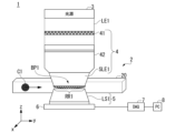
- FIG. 1 is a diagram showing an example of the configuration of a flow cytometer according to a first embodiment of the present invention.
- FIG. 2 is a diagram showing an example of a bright spot pattern according to the first embodiment of the present invention.
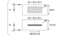
- 5A to 5C are diagrams showing an example of a method for arranging bright spot patterns made of a plurality of wavelengths in an overlapping manner in the depth direction of a flow channel according to the first embodiment of the present invention.
- 5A to 5C are diagrams showing an example of a method for arranging bright spot patterns consisting of a plurality of wavelengths at different positions in the depth direction of a flow channel according to the first embodiment of the present invention.
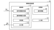
- 1 is a diagram illustrating an example of a configuration of an information processing device according to a first embodiment of the present invention.
- FIG. 2 is a diagram illustrating an example of information processing according to the first embodiment of the present invention.
- FIG. 11 is a diagram showing an example of the configuration of a flow cytometer according to a second embodiment of the present invention.
- FIG. 11 is a diagram showing an example of a bright spot pattern according to a second embodiment of the present invention.
- 1 is a diagram showing an example of the configuration of a flow cytometer according to a first embodiment of the present invention.
- FIG. 11 is a diagram showing an example of the configuration of a flow cytometer according to a second embodiment of the present invention.
- FIG. 13 is a diagram showing an example of the configuration of a flow cytometer according to a third embodiment of the present invention.
- Fig. 1 is a diagram showing an example of the configuration of a flow cytometer 1 according to this embodiment.
- the flow cytometer 1 includes a microfluidic device 2, a light source 3, an illumination optical system 4, a detection optical system 5, a photodetector 6, a DAQ (Data Acquisition) device 7, and a personal computer (PC: Personal Computer) 8.
- PC Personal Computer
- the microfluidic device 2 includes a flow path 20 through which the observation object C1 can flow together with the fluid.
- One example of the observation object C1 is a cell.
- the observation object C1 is not limited to a cell, and may be a microparticle or the like as another example.
- the flow rate of the fluid flowing through the flow path 20 is constant regardless of the type or individual differences of the observation object C1 being passed through.
- the microfluidic device 2 sequentially passes multiple observation objects through the flow path 20, but only one observation object passes through the illumination light irradiation position of the flow path 20 at a time.
- the figure appropriately shows an xyz coordinate system as a three-dimensional Cartesian coordinate system.
- the x-axis direction is the width direction of the flow channel 20.
- the y-axis direction is the length direction of the flow channel 20.
- the z-axis direction is a direction perpendicular to the flow channel 20 and is the depth direction of the flow channel 20.
- the depth direction of the flow channel 20 is also called the height direction of the flow channel 20.
- the flow of liquid in the flow channel 20 moves the observation object C1 in the +y direction of the y-axis direction.
- the length direction of the flow channel 20 is the direction in which the fluid flows in the flow channel, and is also described as the flow direction of the flow channel.
- the width direction of the flow channel 20 or the depth direction of the flow channel 20 is, in other words, the direction perpendicular to the streamline of the fluid flowing with the observation object C1.
- the width and depth of the flow path 20 are equal.
- the cross section of the flow path 20 is square.
- the width and depth of the flow path 20 may be different.
- the cross section of the flow path 20 may be rectangular.
- the light source 3 emits illumination light LE1 toward the observation object C1.
- the illumination light LE1 emitted by the light source 3 includes light of two or more wavelengths.
- the light source 3 simultaneously emits light of two or more wavelengths as the illumination light LE1 toward the observation object C1.
- the light source 3 is, for example, a white light source.
- the light source 3 may be, for example, a light source that combines multiple light sources that emit light of specific wavelengths.
- the light source that emits light of specific wavelengths is, for example, a laser light source, a semiconductor laser light source, or an LED (Light Emitting Diode) light source.
- the illumination light LE1 emitted by the light source 3 may be spatially incoherent light, but spatially coherent light is preferable. In this embodiment, the illumination light LE1 emitted by the light source 3 is, for example, spatially coherent light.
- the illumination optical system 4 irradiates the illumination light LE1 emitted by the light source 3 onto a light irradiation region RR1 of the flow channel 20.
- the light irradiation region RR1 is a predetermined portion of the flow channel 20 onto which the illumination light emitted from the light source 3 is irradiated.
- the illumination optical system 4 includes optical elements such as lenses, mirrors, optical filters, and spectroscopic elements.
- the mirrors include, for example, a half mirror, a dichroic mirror, etc.
- the spectroscopic elements include, for example, a prism, a diffraction grating, etc.
- the illumination optical system 4 includes at least a spatial light modulation element 41 and an illumination objective lens 42.
- the spatial light modulation element 41 and the illumination objective lens 42 are arranged on the optical path between the light source 3 and the photodetector 6 in this order, starting from the side closest to the light source 3.
- the illumination optical system 4 including the spatial light modulation element 41 and the light source 3 function as a configuration for irradiating structured illumination, as described below.
- the flow channel 20 is irradiated with structured illumination light SLE1, as described below.
- the illumination light LE1 emitted from the light source 3 is converted into structured illumination light SLE1 by the spatial light modulation element 41, and the structured illumination light SLE1 is irradiated onto the light irradiation region RR1 of the flow channel 20.
- the spatial light modulation element 41 is disposed on the optical path between the light source 3 and the photodetector 6. In this embodiment, the spatial light modulation element 41 is disposed on the optical path between the light source 3 and the flow path 20.
- This arrangement is also referred to as a structured illumination configuration.
- the illumination light LE1 emitted from the light source 3 is structured by the spatial light modulation element 41, and the structured illumination light SLE1 is irradiated onto the flow path 20.
- the structured illumination light SLE1 is condensed via the irradiation objective lens 42 and is imaged as a bright spot pattern BP1 in the light irradiation region RR1 of the flow path 20.
- the bright spot pattern here is a pattern used in the GMI method to extract morphological information of an observed object as optical information, and is a pattern composed of a distribution of multiple regions with different optical properties such as light intensity.
- the bright spot pattern includes a binary illumination pattern used in structured illumination and a detection position pattern in structured detection.
- the binary illumination pattern is an illumination pattern composed of an area irradiated with light and an area not irradiated with light, as described later.
- the detection position pattern in structured detection is, for example, a pattern composed of detection positions arranged by a transmission area that transmits light of a mask described in the second embodiment.
- the bright spot pattern also includes a pattern composed of a distribution of multiple regions with different optical properties other than the amount of light transmitted.
- the bright spot pattern BP1 is an illumination light pattern composed of multiple regions with different optical characteristics characterized by the spatial light modulation element 41.
- An example of a bright spot pattern in a structured detection configuration will be described later in the second embodiment.
- the spatial light modulator 41 structures the incident light. Structuring the incident light means changing the optical characteristics of the incident light for each of the multiple regions included in the incident surface of the incident light.
- the spatial light modulator 41 structures the illumination light LE1 and converts it into structured illumination light SLE1.
- the spatial light modulator 41 is an optical element that modulates the incident illumination light LE1 and outputs it by changing the spatial distribution of the optical characteristics of the incident light.
- the spatial light modulator 41 makes it possible to control the light irradiation pattern and irradiate light.
- the surface on which the incident light of the spatial light modulator 41 is incident has multiple regions, and the optical characteristics of the illumination light LE1 are individually converted in each of the multiple regions through which it passes.
- the optical characteristics of the light change differently in multiple regions compared to the optical characteristics of the incident light.
- the optical characteristics of the incident light include, but are not limited to, the intensity, wavelength, phase, or polarization of light.
- the optical characteristic that changes upon passage through the spatial light modulation element 41 is not limited to one; two or more optical characteristics may change simultaneously.
- the spatial light modulation element 41 may be, for example, a diffractive optical element (DOE), a spatial light modulator (SLM), or a digital micromirror device (DMD).
- DOE diffractive optical element
- SLM spatial light modulator
- DMD digital micromirror device
- Another example of the spatial light modulation element 41 is a film or filter composed of a plurality of regions in which one or more of light transmittance, reflectivity, absorption, and polarization properties are different from each other, and a film on which a plurality of regions with different optical properties are printed on the surface may also be used as the spatial light modulation element 41.
- the spatial light modulation element 41 is preferably a DMD.
- the spatial modulator 40 is, for example, a DOE.
- the illumination light LE1 emitted from the light source 3 contains light of two or more wavelengths.
- the spatial light modulation element 41 structures the illumination light LE1 for each wavelength and converts it into structured illumination light SLE1. Therefore, the spatial light modulation element 41 imparts a bright spot pattern BP1 to each of the two or more wavelengths of light.
- the illumination light LE1 of different wavelengths is processed by the spatial light modulation element 41 into individual structured illumination light SLE1, and the bright spot patterns derived from the individual structured illumination light SLE1 are irradiated onto the observation object C1 in the light irradiation region RR1 of the flow path 20.
- the spatial light modulation element 41 imparts different bright spot patterns to each of the two or more wavelengths of light.
- the illumination light LE1 contains two wavelengths of light, a first wavelength and a second wavelength
- the spatial light modulation element 41 imparts a first bright spot pattern to the light of the first wavelength and a second bright spot pattern to the light of the second wavelength.
- the bright spot pattern BP1 is composed of a first bright spot pattern and a second bright spot pattern.
- the spatial light modulation element 41 may impart the same bright spot pattern to each of the two or more wavelengths of light.
- the different bright spot patterns constituting the bright spot pattern BP1 overlap at least partially in the longitudinal direction of the flow path 20. It is more preferable that the different bright spot patterns constituting the bright spot pattern BP1 overlap in the longitudinal direction of the flow path 20, as described below.
- the length of the bright spot pattern BP1 in the longitudinal direction of the flow path 20 can be made shorter than when the bright spot patterns do not overlap in the longitudinal direction of the flow path 20.
- the bright spot pattern BP1 is a binary illumination pattern given by structured illumination.
- the binary illumination pattern is, for example, an illumination pattern configured by an area irradiated with light and an area not irradiated with light in the light irradiation region RR1.
- the binary illumination pattern is an illumination pattern in which the intensity of light for each area is one of two values.
- the binary illumination pattern can be generated by, for example, a spatial light modulation element 41 having an area that transmits light and an area that blocks light converting the illumination light LE1 into structured illumination light SLE1.
- the binary illumination pattern can also be configured by a distribution of areas (areas irradiated with strong light and areas irradiated with weak light) with different intensities of irradiation light in the light irradiation region RR1.
- the bright spot pattern BP1 can be generated using an illumination pattern configured by differences in light intensity.
- the bright spot pattern BP1 can also be generated using an illumination pattern configured by differences in optical properties other than the intensity of light.
- FIG. 2 shows an example of a bright spot pattern BP1 when the flow channel 20 is viewed from above in the depth direction of the flow channel 20.
- the bright spot pattern BP1 is composed of a distribution of multiple regions in which at least one optical characteristic differs from the other.
- the bright spot pattern BP1 is a binary pattern in which the multiple regions are composed of two types of regions in which the optical characteristics differ from the other. Note that the optical characteristics differ from the other means that at least one of the multiple types of optical characteristics is different.
- the bright spot pattern BP1 is composed of multiple regions composed of regions with high light intensity and regions with low light intensity.
- the bright spot pattern BP1 is arranged in the light irradiation region RR1 of the flow path by the illumination optical system.
- the range of the light irradiation region RR1 in which the bright spot pattern BP1 is arranged is the range of the light irradiation region RR1 in which the structured illumination light SLE1 is irradiated in a focused state.
- the shape of the area constituting the bright spot pattern BP1 is not particularly limited. At the depth direction position of the flow channel 20 where the structured illumination light SLE1 is focused by the illumination optical system 4, the area constituting the bright spot pattern BP1 can be arranged in a circular, elliptical, or rectangular shape. As an example, the shape of the area constituting the bright spot pattern BP1 shown in Figure 2 is a square.
- the multiple regions constituting the bright spot pattern BP1 can be randomly arranged to form the bright spot pattern.
- the bright spot pattern can be formed by randomly arranging the regions with high light intensity among the multiple regions with different light intensities.
- random means that there is no regularity.
- the bright spot pattern BP1 is not limited to a random pattern.
- the bright spot pattern BP1 may include at least two parts arranged at different positions, and each of the at least two parts may be configured by a distribution of multiple regions based on a Fourier basis.
- the distribution of multiple regions based on a Fourier basis is, for example, a distribution of multiple regions whose arrangement is determined based on pixel values in a two-dimensional image that indicates the Fourier basis.
- the distribution of multiple regions based on a Fourier basis is determined, for example, based on whether the pixel value is large or not.
- the distribution of regions having a first optical characteristic (for example, regions that transmit light) and regions having a second optical characteristic (for example, regions that block light) is determined depending on whether the condition that the pixel value is equal to or greater than a predetermined value, or the condition that the pixel value is equal to or greater than a predetermined rank among all pixels included in the two-dimensional image, is satisfied.
- the classification accuracy can be improved for observed objects of various sizes and shapes compared to when the bright spot pattern BP1 is a random pattern.
- a pattern based on the Fourier basis is considered to have a higher classification accuracy than a random pattern.
- the bright spot pattern BP1 includes at least two parts arranged at different positions from each other, and one of the at least two parts may be composed of a distribution of multiple regions based on a Fourier basis, and the other may be a random pattern.
- the bright spot pattern BP1 can also be formed by arranging areas with stronger light intensity, among a plurality of areas with different light intensities, on one or more straight lines.
- the size of the bright spot pattern BP1 included in the structured illumination light SLE1 (illumination beam) irradiated to the flow channel 20 is, for example, 20 ⁇ m to 100 ⁇ m in the flow direction of the flow channel 20 and 20 ⁇ m to 50 ⁇ m in the width direction of the flow channel.
- the size of the bright spot pattern BP1 here refers to the size of the bright spot pattern at the position focused by the illumination objective lens 42 in the depth direction of the flow channel 20.
- the GMI method in order to extract the morphological information of the object being observed as optical information having the morphological information with higher resolution, it is necessary to continuously irradiate the object being observed with a bright spot pattern BP1 having a length equal to or greater than a predetermined length in the longitudinal direction of the flow path 20.
- the length of the bright spot pattern BP1 in the longitudinal direction of the flow path 20 is short in order to improve throughput.
- the length of the bright spot pattern BP1 in the longitudinal direction of the flow path 20 is shorter than the illumination light irradiated in the conventional GMI method.
- the flow direction length of the flow path of the bright spot pattern is set to about 500 ⁇ m.
- the flow direction length of the flow path 20 of the bright spot pattern BP1 can be set to about 100 ⁇ m.
- the illumination light LE1 containing light of two or more wavelengths is used, and different bright spot patterns are given to each of the two or more wavelengths of light, and the two or more wavelengths are simultaneously irradiated to the flow path 20 as the bright spot pattern BP1, thereby shortening the flow direction length of the flow path 20 of the bright spot pattern BP1 from 20 ⁇ m to about 50 ⁇ m.
- the throughput can be improved by shortening the length of the flow path 20 of the bright spot pattern BP1 in the length direction compared to the length set in the conventional GMI method.
- the length of the bright spot pattern BP1 in the width direction of the flow path 20 is set to be shorter than the width of the flow path 20.
- the suitable length of the bright spot pattern BP1 in the width direction of the flow path 20 varies depending on the length of the flow path width and the size of the object to be observed, but it is preferable to set it to a length of 20 ⁇ m to 50 ⁇ m as shown in FIG. 2.
- a method for arranging a bright spot pattern BP1 consisting of light of multiple wavelengths in the flow path 20 will be further described using an example.
- bright spot pattern BP1 consists of bright spot pattern BP11, bright spot pattern BP12, and bright spot pattern BP13, which are different from each other and assigned to light of three wavelengths, will be described using Figures 3 and 4.
- FIG. 3 is a diagram showing an example of a method for arranging bright spot patterns BP1 consisting of multiple wavelengths in an overlapping manner in the depth direction of the flow channel 20 according to this embodiment.
- Bright spot patterns BP11, BP12, and BP13 are arranged in an overlapping manner in the depth direction of the flow channel 20. Therefore, bright spot patterns BP1 are applied in overlapping relation to each other at the same positions in the depth direction of the flow channel 20 for each of two or more wavelengths of light.
- it is preferable that bright spot patterns BP1 are arranged in a range of approximately 2 ⁇ m to 3 ⁇ m in the depth direction of the flow channel 20.
- the bright spot patterns (bright spot pattern BP11, bright spot pattern BP12, and bright spot pattern BP13) assigned to each of the multiple wavelengths of light included in bright spot pattern BP1 are preferably arranged so as to overlap each other in the flow direction of flow path 20, as shown in FIG. 3(A).
- the bright spot patterns assigned to each of the multiple wavelengths of light included in bright spot pattern BP1 may be arranged so as to be shifted from each other in the flow direction of flow path 20.
- the length of bright spot pattern BP1 in the flow direction of flow path 20 is arranged so as to be shorter than the length of the bright spot pattern used in the conventional GMI method in the flow direction of the flow path.
- the bright spot patterns assigned to each of the multiple wavelengths of light included in the bright spot pattern BP1 are preferably arranged so as to overlap each other in the width direction of the flow path 20, as shown in FIG. 3(A). Note that the bright spot patterns assigned to each of the multiple wavelengths of light included in the bright spot pattern BP1 may be arranged so as to be shifted from each other in the width direction of the flow path 20. Furthermore, the shape of the bright spot pattern BP1 is not limited to the shape shown in FIG. 3.
- Figure 4 is a diagram showing an example of a method for arranging bright spot patterns BP1 consisting of multiple wavelengths in different positions in the depth direction of flow path 20 according to this embodiment.
- bright spot patterns BP11, BP12, and BP13 are arranged in different positions in the depth direction of flow path 20. Therefore, bright spot pattern BP1 is imparted to different positions in the depth direction of flow path 20 for each of two or more wavelengths of light.
- bright spot pattern BP1 i.e., bright spot pattern BP11, bright spot pattern BP12, and bright spot pattern BP13
- the spacing between each bright spot pattern is such that, in FIG. 4(B), the bright spot patterns BP11, BP12, and BP13 are concentrated at a certain depth position in the flow channel 20, but each bright spot pattern can also be spaced apart at an appropriate interval.
- the bright spot patterns (bright spot pattern BP11, bright spot pattern BP12, and bright spot pattern BP13) assigned to each of the multiple wavelengths of light included in bright spot pattern BP1 are preferably arranged so as to overlap each other in the flow direction of flow path 20, as shown in FIG. 4(A).
- the bright spot patterns assigned to each of the multiple wavelengths of light included in bright spot pattern BP1 may be arranged to be shifted from each other in the flow direction of flow path 20.
- the length of bright spot pattern BP1 in the flow direction of flow path 20 is arranged to be shorter than the length of the bright spot pattern used in the conventional GMI method in the flow direction of the flow path.
- the bright spot patterns assigned to each of the multiple wavelengths of light included in the bright spot pattern BP1 are preferably arranged so as to overlap each other in the width direction of the flow path 20, as shown in FIG. 4(A). Note that the bright spot patterns assigned to each of the multiple wavelengths of light included in the bright spot pattern BP1 may be arranged so as to be shifted from each other in the width direction of the flow path 20. Furthermore, the shape of the bright spot pattern BP1 is not limited to the shape shown in FIG. 3.
- the description of the configuration of the flow cytometer 1 will be continued.
- an electromagnetic wave is generated in which the structured illumination light SLE1 is modulated by the observation object C1.
- the electromagnetic wave emitted from the observation object C1 by irradiation with the illumination light LE1 is described as modulated light.
- the modulated light is light emitted from the observation object C1 by irradiation with the structured illumination light SLE1.
- the modulated light includes, for example, scattered light, transmitted light, interference light of transmitted light, and light whose phase is modulated.
- the transmitted light that has passed through the observation object C1 is also described as modulated light.
- the scattered light includes light scattered in the forward direction (forward scattered light), light scattered in the backward direction (backward scattered light), and light scattered in the side direction (side scattered light).
- the modulated light includes shape information of the observation object C1.
- FIG. 1 a configuration for detecting forward scattered light as modulated light will be described with reference to FIG. 1.
- a similar configuration can be applied to modulated light other than forward scattered light.
- the position at which the photodetector 6 is positioned must correspond to the direction in which the backward scattered light or side scattered light propagates.
- the detection optical system 5 guides modulated light from the observation object C1 illuminated with the structured illumination light SLE1 to the photodetector 6.
- the detection optical system 5 is an optical system that focuses the scattered signal light LS1 from the observation object C1 onto the photodetector 6.
- the detection optical system 5 includes optical elements such as lenses, mirrors, optical filters, and spectroscopic elements.
- Mirrors include, for example, half mirrors or dichroic mirrors.
- Spectroscopic elements include, for example, prisms or diffraction gratings.
- the detection optical system 5 includes at least an imaging lens (not shown).
- the imaging lens included in the detection optical system 5 focuses the scattered signal light LS1 from the object of observation C1 at the position of the photodetector 6. Note that the imaging lens does not need to focus the scattered signal light LS1 at the position of the photodetector 6 as long as it focuses the scattered signal light LS1 from the object of observation C1, but it is more preferable that the imaging lens is positioned to focus the scattered signal light LS1 at the position of the photodetector 6.
- the detection optical system 5 may further include a dichroic mirror and a wavelength-selective filter.
- the photodetector 6 detects modulated light from the observation object C1 irradiated with the illumination light LE1 in the light irradiation region RR1 by the illumination optical system 4.
- the photodetector 6 detects modulated light from the observation object C1 irradiated with the illumination light LE1 to which the bright spot pattern BP1 is applied by the spatial light modulator 41, independently for each wavelength.
- the modulated light is the scattered signal light LS1 collected by the imaging lens provided in the detection optical system 5.
- the photodetector 6 detects the scattered signal light LS1 and converts it into an electrical signal.
- the photodetector 6 is a photomultiplier tube (PMT).
- the photodetector 6 detects the intensity of the scattered signal light LS1 collected by the imaging lens 50 in a time series. As described above, the scattered signal light LS1 is emitted from the observation object C1 flowing through the flow path 20 when the structured illumination light SLE1 is irradiated onto the observation object C1. In other words, the photodetector 6 detects the intensity of the scattered signal light LS1 emitted from the observation object C1 flowing through the flow path 20 when the structured illumination light SLE1 is irradiated onto the observation object C1 in a time series manner.
- the photodetector 6 may be a single sensor composed of a single photodetection element, or may be a multi-sensor composed of multiple photodetection elements.
- the photodetector 6 is a multi-sensor composed of multiple photodetection elements
- the photodetector 6 is, for example, an array-type photodetector in which a large number of reusable photodetection elements are arranged on the detection surface.
- the DAQ device 7 converts the electrical signal pulses output by the photodetector 6 into electronic data for each pulse.
- the electronic data includes a pair of time and the intensity of the electrical signal pulse.
- One example of the DAQ device 7 is an oscilloscope.
- the PC8 is a device provided in the flow cytometer 1 that performs information processing.
- the information processing includes a process of generating identification information A1 for identifying the observation object C1.
- the PC8 generates the identification information A1 based on electronic data output from the DAQ device 7.
- the electronic data output from the DAQ device 7 is called signal information D1.
- the signal information D1 is time series data on the intensity of the scattered signal light LS1.
- the signal information D1 is an example of time series optical information that indicates the time series change in the intensity of the modulated light detected by the photodetector 6.
- the PC8 is an example of an information generation unit.
- the information processing device 10 is a feature amount calculation device that calculates feature amounts indicating optical characteristics of an observation object by a flow cytometry method.
- the information processing device 10 generates identification information for identifying the observation object from the optical information acquired by the GMI method, and identifies the observation object based on the identification information.
- the information processing device 10 includes a control unit 11, a storage unit 12, and an input unit 13.
- the control unit 11 includes, for example, a CPU (Central Processing Unit), a GPU (Graphics Processing Unit), an FPGA (field-programmable gate array), etc., and performs various calculations and information transfer.
- Each of the functional units of the control unit 11 is realized, for example, by a CPU loading a program read from a ROM (Read Only Memory) into a RAM (Random Access Memory) and executing processing in accordance with the program.
- the ROM and RAM are included in the storage unit 12.
- the control unit 11 includes a signal information acquisition unit 110, an identification information generation unit 111, a discrimination unit 112, and an output unit 113.
- the signal information acquisition unit 110 acquires signal information D1 from the DAQ device 7.
- the identification information generating unit 111 generates the identification information A1 based on the signal information D1 acquired by the signal information acquiring unit 110.
- the identification information A1 is information for identifying the observed object C1.
- One example of the identification information A1 is a trained model based on machine learning. The trained model is trained to output a result of identifying the observed object C1 when the signal information D1 is input.
- the signal information D1 includes morphological information of the observed object C1.
- the machine learning algorithm may be any algorithm, but is preferably an algorithm that can perform calculations and output results in a time period according to the desired throughput for the flow cytometer 1.
- One example of the machine learning algorithm is a support vector machine.
- the identification information generating unit 111 generates identification information A1 for identifying the observed object C1 based on the time-series optical information indicating the time series of the intensity of the modulated light detected by the photodetector 6.
- the discrimination unit 112 discriminates the observation object C1 from the signal information D1 based on the identification information A1. The discrimination unit 112 discriminates whether the observation object C1 is the intended observation object.
- the output unit 113 outputs the discrimination result B1 indicating the result of the discrimination made by the discrimination unit 112 to an external device (not shown).
- the external device is, for example, a display device such as a display device, a storage device provided in a server, or a printer.
- the output unit 113 may output the discrimination result B1 to the storage unit 12.
- the storage unit 12 stores various types of information.
- the storage unit 12 stores the identification information A1.
- the storage unit 12 is configured using a storage device such as a magnetic hard disk device or a semiconductor storage device.
- the input unit 13 accepts various operations from the user.
- the input unit 13 includes, for example, a mouse, a keyboard, or a touch panel.
- [Information Processing] 6 is a diagram showing an example of information processing according to the present embodiment.
- the information processing here is information processing for determining whether or not the observation object C1 is a target observation object.
- the information processing is executed by the control unit 11 of the information processing device 10.
- the identification information A1 is generated by the identification information generating unit 111 and stored in advance in the storage unit 12 before the information processing is executed.
- Step S10 The signal information acquisition unit 110 acquires the signal information D1 from the DAQ device 7.
- the signal information acquisition unit 110 supplies the acquired signal information D1 to the discrimination unit 112.
- Step S20 The discrimination unit 112 discriminates the observed object C1 from the signal information D1 acquired by the signal information acquisition unit 110 based on the identification information A1.
- the identification information generation unit 111 outputs the discrimination result B1 to the output unit 113.
- Step S30 The output unit 113 outputs the discrimination result B1 output from the discrimination unit 112 to an external device. With this, the control unit 11 ends the information processing.
- the flow cytometer 1a includes a microfluidic device 2, a light source 3, an illumination optical system 4a, a detection optical system 5a, a photodetector 6, a DAQ device 7, and a PC 8.
- the configuration of the flow cytometer 1a (FIG. 7) is similar to that of the flow cytometer 1 (FIG. 1), except that the illumination optical system 4 and the detection optical system 5 are replaced by an illumination optical system 4a and a detection optical system 5a.
- the illumination optical system 4a irradiates the illumination light LE1 emitted by the light source 3 onto the light irradiation region RR1 of the flow path 20.
- the illumination optical system 4a includes at least an illumination objective lens 42.
- the illumination optical system 4a differs from the illumination optical system 4 in that it does not include a spatial light modulation element, but can similarly use optical elements other than the spatial light modulation element that can be used in the illumination optical system 4.
- the detection optical system 5a guides modulated light from the observation object C1 irradiated with the illumination light LE1 to the photodetector 6 via a mask 51a.
- the detection optical system 5a includes at least the mask 51a.
- the detection optical system 5a differs from the detection optical system 5 in that it includes at least the mask 51a.
- the detection optical system 5a can use optical elements such as an imaging lens that can be used in the detection optical system 5 in the same way.
- the mask 51a provides a bright spot pattern BP1 for each of the two or more wavelengths of light contained in the illumination light LE1.
- the mask 51a is an example of a spatial light modulation element.
- the mask 51a is placed on the optical path between the flow path 20 and the photodetector 6.
- a configuration in which a spatial light modulation element (i.e., mask 51a) is placed on the optical path between the flow path 20 and the photodetector 6 is also referred to as a structured detection configuration. More specifically, the mask 51a is placed on the optical path between the flow path 20, the light irradiation region RR1, and the photodetector 6.
- unstructured illumination light LE1 is irradiated onto the observation object C1 from the light source 3.
- the illumination light LE1 is scattered by the observation object C1 to generate scattered signal light LS1, which is structured by the mask 51a.
- the structured scattered signal light LS1 is collected by an optical element included in the detection optical system 5a, and the photodetector 6 detects the collected scattered signal light LS1. Note that in this embodiment as well, the explanation will be given using the scattered signal light LS1 as an example of modulated light modulated by the observation object C1.
- the scattered signal light LS1 In response to the illumination light LE1 containing light of two or more wavelengths, the scattered signal light LS1 also contains light of two or more wavelengths.
- the mask 51a provides a bright spot pattern BP1a for each of the two or more wavelengths of light contained in the scattered signal light LS1.
- the mask 51a is composed of a transmission area that transmits light and a blocking area that blocks light.
- the mask 51a is a spatial light modulation element for structuring the scattered signal light LS1.
- a bright spot pattern characterized by the spatial light modulator is virtually formed in the light irradiation region RR1 of the flow path 20.
- the bright spot pattern is virtually arranged at a position corresponding to the transmission region of the mask 51a in the light irradiation region RR1 of the flow path 20, as shown in FIG. 7, for example.
- the illumination light LE1 including two or more wavelengths irradiated to the light irradiation region RR1 of the flow path 20 is modulated by the observation object C1 at that position and is detected by the photodetector 6 independently for each wavelength. At that time, the detection efficiency of the modulated light detected by the detector differs depending on the position in the light irradiation region RR1.
- the modulated light generated from a position optically conjugate with the individual transmission region of the spatial light modulator in the light irradiation region RR1 is efficiently detected by the photodetector 6, but the modulated light generated from a position optically conjugate with the individual blocking region of the spatial light modulator in the light irradiation region RR1 has a low detection efficiency by the photodetector 6.
- detection positions that can efficiently detect modulated light in the light irradiation region RR1 of the flow channel 20 are arranged according to the distribution of multiple regions in the spatial light modulation element that have different optical characteristics (i.e., the distribution of the transmission regions that make up the mask 51a).
- the bright spot pattern BP1a is characterized by a spatial light modulation element installed in the optical path between the flow path 20 and the photodetector 6.
- the modulated light from the light irradiation region RR1 is detected by the photodetector 6 as modulated light that has been given the bright spot pattern BP1a composed of multiple regions with mutually different optical characteristics.
- modulated light emitted at the position of bright spot pattern BP1a at the detection position of flow path 20 is efficiently detected by photodetector 6 through the transparent region of mask 51a.
- modulated light from observation object C1 irradiated with illumination light LE1 is given bright spot pattern BP1a by the spatial light modulation element (mask 51a as an example), and is detected independently for each wavelength by photodetector 6.
- the position of the bright spot pattern BP1a at the detection position of the flow path 20 will now be described.
- the bright spot pattern BP1a is virtually positioned in the light irradiation region RR1 of the flow path 20.
- the positions of the individual bright spots constituting the bright spot pattern BP1a and the transparent region of the mask 51a are positioned optically conjugate to each other, and modulated light generated at positions corresponding to the individual bright spots is detected by the photodetector 6 via the transparent region of the mask 51a.
- the positions of the individual bright spots of the bright spot pattern BP1a become detection positions. Modulated light generated from the observed object C1 at the detection position is detected by the photodetector 6 via the mask 51a.
- FIG. 8 shows an example of the bright spot pattern BP1a when looking down on the flow path 20 in the depth direction of the flow path 20.
- the bright spot pattern BP1a is composed of a distribution of multiple regions that differ from one another in at least one optical characteristic.
- the bright spot pattern BP1a is a binary pattern in which multiple regions are composed of two types of regions that differ from one another in optical characteristic.
- a binary bright spot pattern can be generated by a mask 51a that is composed of a transparent region and a blocking region.
- the modulated light generated in the light irradiation region RR1 the modulated light generated at a position optically conjugate to the transparent region of the mask 51a is efficiently detected by the photodetector 6.
- the modulated light generated at a position optically conjugate to the blocking region of the mask 51a is difficult to detect by the photodetector 6 because the modulated light is blocked by the blocking region of the mask 51a.
- the bright spot pattern BP1 is arranged in the light irradiation region RR1.
- the range of the light irradiation region RR1 in which the bright spot pattern BP1 is arranged is the range of the light irradiation region RR1 in which the modulated light passes through the structured detection configuration and is detected in a focused state in the structured detection configuration.
- the range in which the modulated light passes through the structured detection configuration and is detected in a focused state is the range in which the image of the mask 51a can be observed in a focused state.
- the shape of the area that constitutes the bright spot pattern BP1a is not particularly limited.
- the area that constitutes the bright spot pattern BP1a can be arranged in a circular, elliptical, or rectangular shape at a position that is conjugate with the transparent area of the mask 51a in the light irradiation area RR1.
- the shape of the area that constitutes the bright spot pattern BP1a shown in Figure 8 is a square.
- the bright spot patterns BP1a may be provided at the same positions in the depth direction of the flow channel 20 for each of two or more wavelengths of light (see FIG. 3), or may be provided at different positions in the depth direction of the flow channel 20 (see FIG. 4).
- the bright spot pattern BP1a is, as an example, a random pattern.
- the bright spot pattern BP1a includes at least two parts arranged at different positions, and the at least two parts may each be composed of a distribution of multiple regions based on a Fourier basis.
- the bright spot pattern BP1a also includes at least two parts arranged at different positions, and one of the at least two parts may be composed of a distribution of multiple regions based on a Fourier basis, and the other may be a random pattern.
- the bright spot pattern BP1 may also be arranged in a straight line.
- the size of the bright spot pattern BP1a can be set to 20 ⁇ m to 100 ⁇ m in the flow direction of the flow path 20, similar to the structured illumination configuration. Although it varies depending on the flow path width and the size of the object to be observed, it is preferable to set the width direction size of the bright spot pattern BP1a of the flow path to 20 ⁇ m to 50 ⁇ m in the flow path width direction as shown in FIG. 8. Note that the size of the bright spot pattern BP1a here refers to the size in the light irradiation region RR1 that is placed at a position conjugate with the transmission region of the mask 51a in the depth direction of the flow path 20.
- Flow cytometer 1b is an example of flow cytometer 1a that acquires modulated light using a structured detection configuration.
- FIG. 9 is a diagram showing an example of the configuration of a flow cytometer 1b according to this embodiment.
- the explanation will focus on the configuration of the optical system that is characteristic of flow cytometer 1b among the configurations of flow cytometer 1a. Note that the same components as those in the above-described embodiment are given the same reference numerals, and explanations of the same components and operations may be omitted.
- the flow cytometer 1 b includes a white light source 3 b as the light source 3 .
- the flow cytometer 1b includes an illumination optical system 4a.
- the flow cytometer 1b includes a detection optical system 5b as the detection optical system 5a.
- the flow cytometer 1 b includes an array-type detector 6 b as the photodetector 6 .
- the white light source 3b emits white light LE1b toward the observation object C1.
- the white light LE1b contains multi-wavelength light.
- the illumination optical system 4a irradiates the flow path 20 with the white light LE1b emitted by the white light source 3b.
- the detection optical system 5b guides the modulated light from the observation object C1 irradiated with the white light LE1b to the array detector 6b.
- the detection optical system 5b includes a detection objective lens 52, a mirror 53, a spectroscopic element 54, an imaging lens 55, and a mask 51b.
- the detection objective lens 52, the mirror 53, the spectroscopic element 54, the imaging lens 55, and the mask 51b are arranged on the optical path between the white light source 3b and the array detector 6b in this order from the side closest to the white light source 3b.
- the detection objective lens 52 guides the modulated light emitted from the observation object C1 to the array detector 6b.
- the modulated light includes scattered signal light LS1 and transmitted light LT1.
- the scattered signal light LS1 is forward scattered light.
- the mirror 53 transmits the scattered signal light LS1 of the modulated light to the array detector 6b.
- the mirror 53 reflects the transmitted light LT1 of the modulated light to a side different from the array detector 6b (e.g., the upper side of the flow path 20).
- the transmitted light LT1 reflected by the mirror 53 is detected by a photodetector (not shown) for detecting transmitted light. Morphological information of the observed object C1 can be obtained from the transmitted light as well as from the scattered light.
- the scattered signal light LS1 transmitted by the mirror 53 is incident on the spectroscopic element 54.
- the spectroscopic element 54 separates the light of two or more wavelengths at an angle according to the wavelength.
- the spectroscopic element 54 is, for example, a prism or a diffraction grating.
- the spectroscopic element 54 separates the light of two or more wavelengths contained in the scattered signal light LS1 at an angle according to the wavelength.
- the scattered signal light LS1 separated by the spectroscopic element 54 is incident on the imaging lens 55.
- the imaging lens 55 forms an image of the scattered signal light LS1 on the detection surface of the array type detector 6b.
- the array detector 6b has a plurality of photodetection elements arranged at different positions on the detection surface.
- a mask 51b is disposed between the imaging lens 55 and the array detector 6b.
- the mask 51b imparts a bright spot pattern to the scattered signal light LS1 separated by the spectroscopic element 54 at an angle according to the wavelength.
- Modulated light sintered signal light LS1 from the observation object C1 illuminated with illumination light (white light LE1b) is separated into light beams at angles according to their wavelengths by the spectroscopic element 54.
- a bright spot pattern is imparted to the separated modulated light (scattered signal light LS1) by the mask 51b, and the array-type detector 6b detects the modulated light imparted with the bright spot pattern independently for each wavelength by a plurality of photodetection elements.
- modulated light (scattered signal light LS1) is separated by the spectroscopic element 54 at an angle according to the wavelength.
- the modulated light is imaged at a different position for each wavelength on the detection surface of array detector 6b, and is detected independently for each wavelength by multiple photodetection elements.
- scattered signal light LS1 from observation object C1 irradiated with white light LE1b can be structured and detected independently for each wavelength using mask 51b and array detector 6b having multiple photodetection elements in a structured detection configuration.
- flow cytometer 1b can classify observation objects with high classification accuracy equivalent to that when the length of the bright spot pattern is extended in the flow direction of flow channel 20, without extending the length of the bright spot pattern in the flow direction of the flow channel.
- the optical configuration has been described for the case where white light is used as illumination light and forward scattered light is detected by the multicolor GMI method using a structured detection configuration, but similar detection can also be performed using a structured illumination configuration without using a structured detection configuration.
- modulated light from the observation object C1 illuminated with white illumination light (structured white illumination light) to which a bright spot pattern has been applied is separated into angles according to wavelength by the spectroscopic element 54, and the separated modulated light is detected independently for each wavelength by multiple light detection elements of the array detector 6b.
- the flow cytometer according to this embodiment is referred to as flow cytometer 1c.
- the flow cytometer 1c is an example of the flow cytometer 1a that acquires modulated light using a structured detection configuration.
- FIG. 10 is a diagram showing an example of the configuration of a flow cytometer 1c according to this embodiment.
- the differences from the configuration of flow cytometer 1b according to the first embodiment will be mainly explained. Note that the same components as those in the first embodiment described above are given the same reference numerals, and explanations of the same components and operations may be omitted.
- the flow cytometer 1 c includes a multi-wavelength light source 3 c as the light source 3 .
- the flow cytometer 1c includes an illumination optical system 4c as the illumination optical system 4a.
- the flow cytometer 1c includes a detection optical system 5b as the detection optical system 5a.
- the flow cytometer 1 c includes an array-type detector 6 b as the photodetector 6 . Comparing the flow cytometer 1c with the flow cytometer 1b, the flow cytometer 1c differs in the multi-wavelength light source 3c and the illumination optical system 4c.
- the multi-wavelength light source 3c emits multi-wavelength illumination light LE1c toward the observation object C1.
- the multi-wavelength illumination light LE1c includes a plurality of light of specific wavelengths. In other words, the multi-wavelength illumination light LE1c has a discrete spectrum.
- the multi-wavelength illumination light LE1c includes light of three wavelengths: a first wavelength light LE11c, a second wavelength light LE12c, and a third wavelength light LE13c.
- the multi-wavelength light source 3c includes a first wavelength light source 31c, a second wavelength light source 32c, and a third wavelength light source 33c.
- the first wavelength light source 31c emits the first wavelength light LE11c toward the observation object C1.
- the second wavelength light source 32c emits the second wavelength light LE12c toward the observation object C1.
- the third wavelength light source 33c emits the third wavelength light LE13c toward the observation object C1.
- the multi-wavelength illumination light LE1c includes light of three wavelengths, but the number of wavelength lights of specific wavelengths that make up the multi-wavelength illumination light LE1c is not limited to this, and may be two or more.
- the illumination optical system 4c irradiates the flow path 20 with multi-wavelength illumination light LE1c emitted by the multi-wavelength light source 3c.
- the illumination optical system 4c includes a condenser lens 43c and an illumination objective lens 42.
- the illumination optical system 4c and the illumination objective lens 42 are disposed on the optical path between the multi-wavelength light source 3c and the array-type detector 6b in this order from the side closer to the multi-wavelength light source 3c.
- the condenser lens 43c mixes light of a plurality of specific wavelengths and condenses the light as multi-wavelength illumination light LE1c having a discrete spectrum.
- the condenser lens 43c causes the multi-wavelength illumination light LE1c obtained by condensing the light to be incident on the irradiation objective lens 42.
- the illumination optical system 4c may further include other optical elements such as lenses, mirrors, optical filters, and dispersive elements as necessary.
- the detection optical system 5b guides modulated light from the observation object C1 irradiated with the multi-wavelength illumination light LE1c to the array detector 6b.
- the scattered signal light LS1c is modulated light emitted from the observation object C1 when the observation object C1 is irradiated with the multi-wavelength illumination light LE1c.
- the scattered signal light LS1c contains light of three wavelengths, since the multi-wavelength illumination light LE1c contains light of three wavelengths.
- the dispersing element 54 separates the light of the three wavelengths contained in the scattered signal light LS1c into angles according to the wavelengths.
- the dispersing element 54 is a prism or a diffraction grating. However, if the number of lights of different wavelengths contained in the multi-wavelength illumination light LE1c is small, a dichroic mirror may be used as the dispersing element 54.
- the modulated light (scattered signal light LS1c) is separated by the spectroscopic element 54 at angles according to the wavelength. In response to this, the modulated light is imaged at different positions for each wavelength on the detection surface of the array detector 6b.
- the length of the bright spot pattern in the length direction of the flow channel 20 can be effectively extended by the number of lights with different wavelengths contained in the multi-wavelength illumination light LE1c. That is, in the flow cytometer 1c, the observed object can be classified with high classification accuracy equivalent to that in the case where the length of the bright spot pattern is extended in the flow direction of the flow channel 20, without extending the length of the bright spot pattern in the flow direction of the flow channel.
- the bright spot pattern can be arranged at different positions in the depth direction of the flow channel 20 by the number of lights with different wavelengths, so that the types of information that can be acquired, such as three-dimensional morphological information, can be increased.
- light having a discrete spectrum is used as illumination light, and the optical configuration is described for detecting forward scattered light by the multi-color GMI method using a structured detection configuration.
- similar detection can also be performed using a structured illumination configuration without using a structured detection configuration.
- the structured illumination configuration and the structured detection configuration may be combined.
- a case will be described in which light having a discrete spectrum is structured by the structured illumination configuration, and forward scattered light is detected by the multicolor GMI method by the structured detection configuration.
- the flow cytometer according to this embodiment is referred to as flow cytometer 1d.
- FIG. 11 is a diagram showing an example of the configuration of a flow cytometer 1d according to this embodiment.
- the differences from the configuration of flow cytometer 1c according to the second embodiment will be mainly explained. Note that the same components as those in the second embodiment described above are given the same reference numerals, and explanations of the same components and operations may be omitted.
- the flow cytometer 1 d includes a multi-wavelength light source 3 c as the light source 3 .
- the flow cytometer 1d includes an illumination optical system 4d as the illumination optical system 4a.
- the flow cytometer 1d includes a detection optical system 5b as the detection optical system 5a.
- the flow cytometer 1 d includes an array-type detector 6 b as the photodetector 6 . Comparing the flow cytometer 1d with the flow cytometer 1c, the illumination optical system 4d is different.
- the multi-wavelength light source 3c and the illumination optical system 4d function as a structured illumination.
- the multi-wavelength light source 3c emits multi-wavelength illumination light LE1c toward the observation object C1, similarly to the second embodiment.
- the illumination optical system 4d includes a spatial light modulation element 41d, a condenser lens 43d, a spectroscopic element 44d, an imaging lens 45d, and an irradiation objective lens 42.
- the spatial light modulation element 41d, the condenser lens 43d, the spectroscopic element 44d, the imaging lens 45d, and the irradiation objective lens 42 are arranged on the optical path between the multi-wavelength light source 3c and the array type detector 6b in this order from the side closer to the multi-wavelength light source 3c.
- the multi-wavelength illumination light LE1c emitted from the multi-wavelength light source 3c is converted into a structured multi-wavelength structured illumination light SLE1d through the spatial light modulation element 41d.
- the spatial light modulation element 41d imparts a bright spot pattern to each of the multiple wavelengths contained in the multi-wavelength illumination light LE1c.
- the spatial light modulation element 41d includes a first wavelength spatial light modulation element 411d, a second wavelength spatial light modulation element 412d, and a third wavelength spatial light modulation element 413d.
- the first wavelength spatial light modulation element 411d imparts a bright spot pattern to the first wavelength light LE11c.
- the second wavelength spatial light modulation element 412d imparts a bright spot pattern to the second wavelength light LE12c.
- the third wavelength spatial light modulation element 413d imparts a bright spot pattern to the third wavelength light LE13c.
- the bright spot patterns provided are different between the first wavelength light LE11c, the second wavelength light LE12c, and the third wavelength light LE13c.
- the focusing lens 43d mixes the light of the multiple specific wavelengths contained in the multi-wavelength structured illumination light SLE1d and focuses it as multi-wavelength structured illumination light SLE1d having a discrete spectrum.
- the focusing lens 43d causes the multi-wavelength structured illumination light SLE1d obtained by focusing to be incident on the spectroscopic element 44d.
- the focusing lens 43d causes the light of the multiple specific wavelengths contained in the multi-wavelength structured illumination light SLE1d to be incident on the spectroscopic element 44d at an angle according to the wavelength.
- the light separating element 44d causes light of a plurality of specific wavelengths, which is incident at an angle according to the wavelength, to travel in a predetermined direction, which is a direction toward the irradiation objective lens 42.
- the dispersing element 44d is, for example, a prism or a diffraction grating. However, when the number of light beams with different wavelengths included in the multi-wavelength structured illumination light SLE1d is small, a dichroic mirror may be used as the dispersing element 44d.
- the imaging lens 45d guides the multi-wavelength structured illumination light SLE1d to the illumination objective lens 42.
- the illumination objective lens 42 forms an image of the vicinity of the surface of the spatial light modulation element 41d in the light illumination region RR1 of the flow channel 20. That is, the illumination objective lens 42 forms an image of the multi-wavelength structured illumination light SLE1d obtained by structuring the multi-wavelength illumination light LE1c by the spatial light modulation element 41d as a bright spot pattern in the light illumination region RR1.
- the scattered signal light LS1d is modulated light emitted from the observation object C1 when the multi-wavelength structured illumination light SLE1d is irradiated onto the observation object C1.
- the scattered signal light LS1d contains three wavelengths of light, since the multi-wavelength structured illumination light SLE1d contains three wavelengths of light.
- the process by which the scattered signal light LS1d is detected by the array detector 6b is the same as in the first embodiment, and therefore will not be described.
- the modulated light (scattered signal light LS1d) is separated by the spectroscopic element 54 at an angle according to the wavelength. Accordingly, the modulated light is imaged at a different position for each wavelength on the detection surface of the array detector 6b.
- the length of the flow path 20 of the bright spot pattern can be effectively extended by the number of different wavelengths of light contained in the multi-wavelength structured illumination light SLE1d.
- design freedom can be given to the position in the depth direction of the flow path 20 where the bright spot pattern is arranged by the number of different wavelengths of light.
- the flow cytometer according to each embodiment includes a light source 3, a microfluidic device 2, an illumination optical system (in each embodiment, an illumination optical system 4 or an illumination optical system 4a), a photodetector 6, a detection optical system (in each embodiment, a detection optical system 5 or a detection optical system 5a), and an information generation unit (in each embodiment, an information processing device 10).
- the light source 3 emits illumination light LE1 toward the observation object C1.
- the microfluidic device 2 includes a flow channel 20 through which an observation object C1 can flow together with a fluid.
- the illumination optical system (illumination optical system 4 or illumination optical system 4 a in each embodiment) guides illumination light LE 1 emitted by the light source 3 to a light irradiation region RR 1 of the flow channel 20 .
- the light detector 6 detects modulated light from the object to be observed C1 illuminated with illumination light (in each embodiment, structured illumination light SLE1 or illumination light LE1) in the light irradiation region RR1 by an illumination optical system (in each embodiment, the illumination optical system 4 or the illumination optical system 4a).
- the detection optical system guides modulated light (in each embodiment, the scattered signal light LS1) from the object of observation C1 illuminated with illumination light (in each embodiment, the structured illumination light SLE1, or the illumination light LE1) to the photodetector 6.
- the information generating unit (in each embodiment, the information processing device 10) generates identification information A1 for identifying the observed object C1 based on time series optical information (in each embodiment, the signal information D1) indicating the time series of the intensity of the modulated light (in each embodiment, the scattered signal light LS1) detected by the photodetector 6.
- the illumination light LE1 emitted by the light source 3 contains light of two or more wavelengths.
- At least one of the illumination optical system (in each embodiment, the illumination optical system 4 or the illumination optical system 4a) or the detection optical system (in each embodiment, the detection optical system 5 or the detection optical system 5a) has a spatial light modulation element (in each embodiment, the spatial light modulation element 41 or the mask 51a) that imparts a bright spot pattern (in each embodiment, the bright spot pattern BP1 or the bright spot pattern BP1a) to each of the two or more wavelengths of light.
- the photodetector 6 detects independently for each wavelength modulated light (in the first embodiment, scattered signal light LS1) from the observation object C1 irradiated with illumination light (in the first embodiment, structured illumination light SLE1) to which a bright spot pattern (in the first embodiment, bright spot pattern BP1) has been imparted by a spatial light modulator (in the first embodiment, spatial light modulator 41), or modulated light (in the second embodiment, scattered signal light LS1) from the observation object C1 irradiated with illumination light (in the second embodiment, illumination light LE1) to which a bright spot pattern (in the second embodiment, bright spot pattern BP1a) has been imparted by a spatial light modulator (in the second embodiment, mask 51a).
- a spatial light modulator in the first embodiment, spatial light modulator 41
- modulated light in the second embodiment, scattered signal light LS1 from the observation object C1 irradiated with illumination light (in the second embodiment, illumination light LE1) to which a bright spot pattern (in the second embodiment, bright spot pattern
- the flow cytometer according to each embodiment can cause the object being observed to experience as many bright spot patterns as there are wavelengths, thereby shortening the time required for measurement while maintaining the high classification accuracy achieved by the conventional GMI method.
- the spatial light modulation element in each embodiment, the spatial light modulation element 41 or the mask 51a, imparts a different bright spot pattern (in each embodiment, the bright spot pattern BP1 or the bright spot pattern BP1a) to each of the two or more wavelengths of light.
- the flow cytometer of each embodiment can allow the object to experience as many different bright spot patterns as there are wavelengths, thereby shortening the time required for measurement while maintaining the high classification accuracy obtained with the conventional GMI method.
- the flow cytometer according to each embodiment can reduce the time required for measurement while maintaining the high classification accuracy obtained by the conventional GMI method.
- the length in the flow direction of the flow path of the bright spot pattern that causes light of each wavelength to act on the object being observed can be made shorter than when light of one wavelength is used, so the time required for measurement is reduced and the measurement speed of the flow cytometer can be improved. In other words, the time required for measurement for each object being observed can be reduced.
- the object to be observed can experience different bright spot patterns equal to the number of wavelengths. Therefore, it is possible to obtain the same discrimination accuracy as when the object to be observed experiences a bright spot pattern using light of one wavelength that has a long bright spot pattern in the flow direction of the flow path.
- the length of the bright spot pattern in the flow path in the flow direction can be shortened, and accordingly the light irradiation area in the flow path can be narrowed.
- narrowing the light irradiation area preferably means shortening the length of the light irradiation area in the flow path in the flow direction.
- the flow cytometer according to each embodiment is compatible with a high NA.
- the flow cytometer according to each embodiment can simultaneously irradiate light of different wavelengths, thereby simultaneously obtaining information derived from differences in wavelength from the same object of observation.
- Information derived from differences in wavelength is, for example, a transmission spectrum (or absorption spectrum).
- the flow cytometer according to each embodiment can simultaneously obtain differences in light absorption derived from differences in wavelength of the object of observation.
- different bright spot patterns for each wavelength can be arranged at different positions in the depth direction of the flow channel.
- the bright spot patterns can be used to optically apply light of different wavelengths to the object of observation at the same time, making it possible to perform structured illumination or structured detection.
- a program for realizing the functions of any of the components in any of the above-described devices may be recorded on a computer-readable recording medium, and the program may be read into a computer system and executed.
- computer system includes hardware such as an operating system or peripheral devices.
- computer-readable recording medium refers to portable media such as flexible disks, optical magnetic disks, ROMs, and CDs (Compact Discs)-ROMs (Read Only Memory), as well as storage devices such as hard disks built into computer systems.
- the term "computer-readable recording medium” also includes devices that hold a program for a certain period of time, such as volatile memory inside a computer system that becomes a server or client when a program is transmitted via a network such as the Internet or a communication line such as a telephone line.
- the volatile memory may be, for example, a RAM (Random Access Memory).
- the recording medium may be, for example, a non-transitory recording medium.
- the above-mentioned program may be transmitted from a computer system in which the program is stored in a storage device or the like to another computer system via a transmission medium, or by a transmission wave in the transmission medium.
- the "transmission medium” that transmits the program refers to a medium having a function of transmitting information, such as a network such as the Internet or a communication line such as a telephone line.
- the above program may be for implementing some of the above functions.
- the above program may be a so-called differential file that can implement the above functions in combination with a program already recorded in the computer system.
- the differential file may be called a differential program.
- each process in the embodiment may be realized by a processor that operates based on information such as a program, and a computer-readable recording medium that stores information such as the program.
- the functions of each part of the processor may be realized by individual hardware, or the functions of each part may be realized by integrated hardware.
- the processor may include hardware, and the hardware may include at least one of a circuit for processing digital signals and a circuit for processing analog signals.
- the processor may be configured using one or more circuit devices mounted on a circuit board, or one or both of one or more circuit elements.
- An IC (Integrated Circuit) or the like may be used as the circuit device, and a resistor or a capacitor may be used as the circuit element.
- the processor may be, for example, a CPU.
- the processor is not limited to a CPU, and various processors such as a GPU (Graphics Processing Unit) or a DSP (Digital Signal Processor) may be used.
- the processor may be, for example, a hardware circuit using an ASIC (Application Specific Integrated Circuit).
- the processor may be, for example, a plurality of CPUs, or a hardware circuit using a plurality of ASICs.
- the processor may be, for example, a combination of a plurality of CPUs and a hardware circuit using a plurality of ASICs.
- the processor may include, for example, one or more of an amplifier circuit or a filter circuit that processes an analog signal.
Landscapes
- Physics & Mathematics (AREA)
- Health & Medical Sciences (AREA)
- Life Sciences & Earth Sciences (AREA)
- Chemical & Material Sciences (AREA)
- Analytical Chemistry (AREA)
- Biochemistry (AREA)
- General Health & Medical Sciences (AREA)
- General Physics & Mathematics (AREA)
- Immunology (AREA)
- Pathology (AREA)
- Investigating Or Analysing Materials By Optical Means (AREA)
Priority Applications (1)
| Application Number | Priority Date | Filing Date | Title |
|---|---|---|---|
| JP2024573025A JPWO2024157903A1 (https=) | 2023-01-25 | 2024-01-19 |
Applications Claiming Priority (2)
| Application Number | Priority Date | Filing Date | Title |
|---|---|---|---|
| US202363440920P | 2023-01-25 | 2023-01-25 | |
| US63/440,920 | 2023-01-25 |
Publications (1)
| Publication Number | Publication Date |
|---|---|
| WO2024157903A1 true WO2024157903A1 (ja) | 2024-08-02 |
Family
ID=91970652
Family Applications (1)
| Application Number | Title | Priority Date | Filing Date |
|---|---|---|---|
| PCT/JP2024/001530 Ceased WO2024157903A1 (ja) | 2023-01-25 | 2024-01-19 | フローサイトメータ |
Country Status (2)
| Country | Link |
|---|---|
| JP (1) | JPWO2024157903A1 (https=) |
| WO (1) | WO2024157903A1 (https=) |
Citations (5)
| Publication number | Priority date | Publication date | Assignee | Title |
|---|---|---|---|---|
| JP2008511843A (ja) * | 2004-09-01 | 2008-04-17 | ハネウェル・インターナショナル・インコーポレーテッド | フローサイトメトリ用の多波長光の周波数多重化検出 |
| JP2013061244A (ja) * | 2011-09-13 | 2013-04-04 | Sony Corp | 微小粒子測定装置 |
| WO2016136801A1 (ja) * | 2015-02-24 | 2016-09-01 | 国立大学法人東京大学 | 動的高速高感度イメージング装置及びイメージング方法 |
| WO2017073737A1 (ja) * | 2015-10-28 | 2017-05-04 | 国立大学法人東京大学 | 分析装置 |
| JP2022014213A (ja) * | 2020-07-06 | 2022-01-19 | シンクサイト株式会社 | フローサイトメータ、イメージング装置、位置検出方法、及びプログラム |
-
2024
- 2024-01-19 JP JP2024573025A patent/JPWO2024157903A1/ja active Pending
- 2024-01-19 WO PCT/JP2024/001530 patent/WO2024157903A1/ja not_active Ceased
Patent Citations (5)
| Publication number | Priority date | Publication date | Assignee | Title |
|---|---|---|---|---|
| JP2008511843A (ja) * | 2004-09-01 | 2008-04-17 | ハネウェル・インターナショナル・インコーポレーテッド | フローサイトメトリ用の多波長光の周波数多重化検出 |
| JP2013061244A (ja) * | 2011-09-13 | 2013-04-04 | Sony Corp | 微小粒子測定装置 |
| WO2016136801A1 (ja) * | 2015-02-24 | 2016-09-01 | 国立大学法人東京大学 | 動的高速高感度イメージング装置及びイメージング方法 |
| WO2017073737A1 (ja) * | 2015-10-28 | 2017-05-04 | 国立大学法人東京大学 | 分析装置 |
| JP2022014213A (ja) * | 2020-07-06 | 2022-01-19 | シンクサイト株式会社 | フローサイトメータ、イメージング装置、位置検出方法、及びプログラム |
Also Published As
| Publication number | Publication date |
|---|---|
| JPWO2024157903A1 (https=) | 2024-08-02 |
Similar Documents
| Publication | Publication Date | Title |
|---|---|---|
| CN111855621B (zh) | 动态高速高灵敏度成像装置及成像方法 | |
| JP6484071B2 (ja) | 物体検出装置 | |
| US9357202B2 (en) | High resolution imaging devices with wide field and extended focus | |
| US8767216B2 (en) | Holographically illuminated imaging devices | |
| US12339217B2 (en) | Flow cytometer | |
| JPH08327529A (ja) | 流体の光学検査のための、特に血液学的分析のための装置 | |
| JP2004170977A (ja) | 分解能の深度で試料を光学的に把握する方法および配置 | |
| JP7697722B2 (ja) | フローサイトメータ、及び位置検出方法 | |
| JP7223752B2 (ja) | 粒子径分布測定装置及び粒子径分布測定装置用プログラム | |
| CN116046649A (zh) | 一种基于流体动力聚焦的成像系统 | |
| US20100264294A1 (en) | Multi-focal spot generator and multi-focal multi-spot scanning microscope | |
| US20230266229A1 (en) | Flow cytometer, cell sorter, optical information generation method, and program | |
| WO2024157903A1 (ja) | フローサイトメータ | |
| KR101641777B1 (ko) | 이미지 생성 장치 및 이미지 생성 방법 | |
| JP7205781B2 (ja) | 光学計測装置 | |
| US20240183773A1 (en) | Flow cytometer | |
| EP4400818A1 (en) | Wavefront measurement device and wavefront measurement method | |
| WO2024177073A1 (ja) | 光学素子、フローサイトメータ、輝点パターン最適化装置、輝点パターン最適化方法、及びプログラム | |
| JP7566302B2 (ja) | フローサイトメータ、観測対象物判別方法、及びプログラム | |
| US20250044211A1 (en) | Flow cytometer, position calculation method, and program | |
| EP3627205A1 (en) | Confocal laser scanning microscope configured for generating line foci | |
| Tan et al. | Imaging-free object recognition enabled by optical coherence | |
| US20250060301A1 (en) | Flow cytometer, discrimination method, and program | |
| US20240230507A1 (en) | Feature value calculation device, feature value calculation method, and program | |
| WO2023062831A1 (ja) | フローサイトメータ、位置算出方法、及びプログラム |
Legal Events
| Date | Code | Title | Description |
|---|---|---|---|
| 121 | Ep: the epo has been informed by wipo that ep was designated in this application |
Ref document number: 24747231 Country of ref document: EP Kind code of ref document: A1 |
|
| WWE | Wipo information: entry into national phase |
Ref document number: 2024573025 Country of ref document: JP |
|
| NENP | Non-entry into the national phase |
Ref country code: DE |
|
| 122 | Ep: pct application non-entry in european phase |
Ref document number: 24747231 Country of ref document: EP Kind code of ref document: A1 |