WO2024157651A1 - タッチセンサ用部材 - Google Patents
タッチセンサ用部材 Download PDFInfo
- Publication number
- WO2024157651A1 WO2024157651A1 PCT/JP2023/045200 JP2023045200W WO2024157651A1 WO 2024157651 A1 WO2024157651 A1 WO 2024157651A1 JP 2023045200 W JP2023045200 W JP 2023045200W WO 2024157651 A1 WO2024157651 A1 WO 2024157651A1
- Authority
- WO
- WIPO (PCT)
- Prior art keywords
- ground conductor
- touch sensor
- wirings
- region
- escape
- Prior art date
- Legal status (The legal status is an assumption and is not a legal conclusion. Google has not performed a legal analysis and makes no representation as to the accuracy of the status listed.)
- Ceased
Links
Images





Classifications
-
- G—PHYSICS
- G06—COMPUTING OR CALCULATING; COUNTING
- G06F—ELECTRIC DIGITAL DATA PROCESSING
- G06F3/00—Input arrangements for transferring data to be processed into a form capable of being handled by the computer; Output arrangements for transferring data from processing unit to output unit, e.g. interface arrangements
- G06F3/01—Input arrangements or combined input and output arrangements for interaction between user and computer
- G06F3/03—Arrangements for converting the position or the displacement of a member into a coded form
- G06F3/041—Digitisers, e.g. for touch screens or touch pads, characterised by the transducing means
-
- G—PHYSICS
- G06—COMPUTING OR CALCULATING; COUNTING
- G06F—ELECTRIC DIGITAL DATA PROCESSING
- G06F3/00—Input arrangements for transferring data to be processed into a form capable of being handled by the computer; Output arrangements for transferring data from processing unit to output unit, e.g. interface arrangements
- G06F3/01—Input arrangements or combined input and output arrangements for interaction between user and computer
- G06F3/03—Arrangements for converting the position or the displacement of a member into a coded form
- G06F3/041—Digitisers, e.g. for touch screens or touch pads, characterised by the transducing means
- G06F3/044—Digitisers, e.g. for touch screens or touch pads, characterised by the transducing means by capacitive means
Definitions
- This disclosure relates generally to touch sensor components, and more specifically to touch sensor components used in capacitive touch sensors.
- Patent Document 1 discloses a sheet-shaped conductor used in a touch panel (touch sensor).
- the sheet-shaped conductor comprises an insulator, a first detection electrode, and a second detection electrode.
- the first detection electrode is provided on one side of the insulator.
- the second detection electrode is provided on the other side of the insulator.
- the first detection electrode and the second detection electrode are configured in a mesh shape using thin metal wires.
- the present disclosure aims to provide a touch sensor component that can improve the detection accuracy of capacitance in a touch sensor.
- a touch sensor member is used in a capacitive touch sensor.
- the touch sensor member includes a substrate.
- the substrate has a first conductor layer, a second conductor layer, and an insulating layer.
- the insulating layer is provided between the first conductor layer and the second conductor layer.
- the insulating layer has electrical insulation properties.
- the first conductor layer includes a plurality of receiving electrodes and a plurality of first outgoing wirings.
- the plurality of receiving electrodes are arranged in a first region when viewed from the thickness direction of the substrate.
- the plurality of receiving electrodes are aligned in a first direction perpendicular to the thickness direction.
- the plurality of first outgoing wirings are connected to the plurality of receiving electrodes.
- the second conductor layer includes a plurality of transmitting electrodes and a plurality of second outgoing wirings.
- the plurality of transmitting electrodes are arranged in the first region when viewed from the thickness direction.
- the plurality of transmitting electrodes are aligned in a second direction.
- the second direction is perpendicular to both the thickness direction and the first direction.
- the second outgoing wirings are connected to the transmitting electrodes.
- the shape of each of the receiving electrodes is a line extending along the second direction.
- the shape of each of the transmitting electrodes is a line extending along the first direction.
- the second region is arranged in the second direction with respect to the first region.
- the receiving electrodes there is an area between any two receiving electrodes adjacent to each other in the first direction.
- a predetermined first outgoing wiring among the first outgoing wirings has a shield portion and a connecting portion.
- the shield portion faces two areas on both sides of a predetermined receiving electrode connected to the predetermined first outgoing wiring in the second direction.
- the connecting portion has a first end connected to the predetermined receiving electrode and a second end connected to the shield portion. The shield portion extends from the second end of the connecting portion to both sides in the first direction.
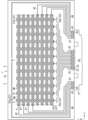
- FIG. 1 is a plan view of a touch sensor member according to a first embodiment.
- FIG. 2 is a cross-sectional view of the touch sensor member.
- FIG. 3 is a plan view of a part of the touch sensor member according to the first embodiment.
- FIG. 4 is a plan view of a part of a first conductor layer of the touch sensor member according to the first embodiment.
- FIG. 5 is a plan view of a part of a second conductor layer of the touch sensor member according to the embodiment.
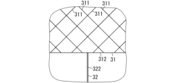
- FIG. 6 is an enlarged view of a receiving electrode of the touch sensor member according to the embodiment of the present invention.
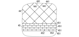
- FIG. 7 is an enlarged view of a second ground conductor and a third ground conductor of the touch sensor member according to the first embodiment.
- FIG. 8 is a plan view of a part of the touch sensor member according to the above.
- FIG. 9 is a plan view of a portion of a member for a touch sensor according to the second embodiment.
- FIG. 10 is a plan view of a part of a second conductor layer of the touch sensor member according to the embodiment.
- FIG. 11 is a plan view of a portion of a member for a touch sensor according to the third embodiment.
- FIG. 12 is a plan view of a portion of a member for a touch sensor according to the fourth embodiment.
- FIG. 13 is a plan view of a portion of a member for a touch sensor according to embodiment 5.
- FIG. FIG. 14 is a cross-sectional view of a touch sensor member according to one modified example.
- the touch sensor member of the present disclosure is described with reference to the drawings.
- the following embodiments are merely a portion of the various embodiments of the present disclosure.
- the following embodiments can be modified in various ways depending on the design, etc., as long as the object of the present disclosure can be achieved.
- the figures described in the following embodiments are schematic diagrams, and the ratios of the sizes and thicknesses of the components in the figures do not necessarily reflect the actual dimensional ratios.
- directions may be mentioned in the description, this is not intended to limit the direction in which the touch sensor member can be used.
- the X-axis direction is a direction along the longitudinal direction of the transmitting electrode 41 of the touch sensor member 2.
- the Y-axis direction is perpendicular to the X-axis direction and is a direction along the longitudinal direction of the receiving electrode 31 of the touch sensor member 2.
- the Z-axis direction is a direction perpendicular to both the X-axis direction and the Y-axis direction. Note that the X-axis, Y-axis, and Z-axis in Fig. 1 and Fig. 2 are merely depicted for the purpose of explanation and do not have any substance.
- the touch sensor 1 includes, for example, a touch sensor member 2, a cover member 11, and an outer wiring portion 12.
- the cover member 11 is translucent.
- the cover member 11 is made of, for example, glass or synthetic resin.
- the cover member 11 has a plate-like shape.
- the cover member 11 and the touch sensor member 2 each have a rectangular shape, for example.
- the outer edge of the cover member 11 is located outside the outer edge of the touch sensor member 2.
- the cover member 11 and the touch sensor member 2 are aligned in the Z-axis direction.
- the cover member 11 and the touch sensor member 2 are bonded together by a transparent adhesive layer.
- the cover member 11 covers the touch sensor member 2.
- the outer wiring section 12 is, for example, a flexible substrate.
- the outer wiring section 12 includes wiring.
- the wiring of the outer wiring section 12 is electrically connected to the wiring of the touch sensor member 2.
- the outer wiring section 12 electrically connects the touch sensor member 2 to a power source that applies a drive voltage to the multiple transmission electrodes 41 of the touch sensor member 2.
- the outer wiring section 12 outputs a signal corresponding to a change in electrostatic capacitance detected by the touch sensor member 2 to an external device.
- the touch sensor 1 is used as an input device for equipment (for example, in-vehicle devices such as car navigation systems, display devices for personal computers, mobile phones, personal digital assistants, portable game machines, copy machines, ticket vending machines, automated teller machines, or clocks, etc.).
- equipment for example, in-vehicle devices such as car navigation systems, display devices for personal computers, mobile phones, personal digital assistants, portable game machines, copy machines, ticket vending machines, automated teller machines, or clocks, etc.
- the touch sensor 1 is used in combination with an image display device such as a liquid crystal display or an organic electroluminescence display.
- the touch sensor 1 includes a first region R1, and the touch sensor 1 is configured to be translucent in the first region R1. More specifically, the first region R1 overlaps with a portion of the cover member 11, and the portion of the cover member 11 that overlaps with the first region R1 is configured to be translucent.
- the portion of the cover member 11 outside the first region R1 is configured to be non-translucent by decoration (e.g., painting or coloring).
- the user can obtain visual information from the image display device arranged behind the touch sensor 1 via the first region R1.
- the touch sensor 1 detects the touch operation.
- the first region R1 is the touch area where the touch operation is performed.
- the front surface of the cover member 11 is the operation surface 110 that is contacted by an indicator (e.g., a conductive body such as a user's fingertip, a stylus, or a pointer) in response to a touch operation.
- an indicator e.g., a conductive body such as a user's fingertip, a stylus, or a pointer
- the touch sensor 1 detects capacitance using a mutual capacitance method. That is, a drive voltage is applied to the multiple transmitting electrodes 41 of the touch sensor 1, and when a pointer touches the operation surface 110, the touch sensor 1 detects a change in capacitance between the transmitting electrode 41 and the receiving electrode 31 provided near the contact point.
- a touch sensor member 2 of the present embodiment is used in a capacitive touch sensor 1.
- the touch sensor member 2 includes a substrate S1.
- the substrate S1 has a first conductor layer 3, a second conductor layer 4, and an insulating layer 51.
- the insulating layer 51 is provided between the first conductor layer 3 and the second conductor layer 4.
- the insulating layer 51 has electrical insulation properties.
- the first conductor layer 3 includes a plurality of receiving electrodes 31 and a plurality of first escape wirings 32.
- the plurality of receiving electrodes 31 are arranged in a first region R1 when viewed from the thickness direction (Z-axis direction) of the substrate S1.
- a translucent region of the cover member 11 coincides with the first region R1.
- the plurality of receiving electrodes 31 are arranged in a first direction (X-axis direction) perpendicular to the thickness direction.
- the plurality of first escape wirings 32 are connected to the plurality of receiving electrodes 31.
- the second conductor layer 4 includes a plurality of transmitting electrodes 41 and a plurality of second outgoing wirings 42.
- the plurality of transmitting electrodes 41 are arranged in the first region R1 when viewed from the thickness direction.
- the plurality of transmitting electrodes 41 are arranged in a second direction (Y-axis direction). The second direction is perpendicular to both the thickness direction and the first direction.
- the plurality of second outgoing wirings 42 are connected to the plurality of transmitting electrodes 41.
- Each of the multiple receiving electrodes 31 is shaped like a line extending along the second direction.
- Each of the multiple transmitting electrodes 41 is shaped like a line extending along the first direction.
- each of the multiple first outgoing wirings 32 is provided from the first peripheral portion of the first region R1 to the second peripheral portion of the second region R2.
- the second region R2 is arranged in the second direction with respect to the first region R1.
- a specific first outgoing wiring 32 has a shield portion 321 (see FIG. 4) and a connecting portion 322 (see FIG. 4).
- the shield portion 321 faces in the second direction two areas M1 on both sides of the specific receiving electrode 31 connected to the specific first outgoing wiring 32.
- the connecting portion 322 has a first end t1 (see FIG.
- the shield part 321 extends from the second end t2 of the connecting part 322 to both sides in the first direction. In other words, the shield part 321 extends from the second end t2 to the positive side and the negative side of the X-axis.
- the electric field generated from a portion of the transmission electrode 41 is absorbed and suppressed by the shield portion 321 of a given first outgoing wiring 32, thereby reducing the possibility that the electric field generated from the portion will be transmitted as noise to another first outgoing wiring 32 adjacent to the given first outgoing wiring 32.
- all the first outgoing wirings 32 have a shield portion 321 and a connecting portion 322. That is, all the first outgoing wirings 32 correspond to a predetermined first outgoing wiring 32 having a shield portion 321 and a connecting portion 322. Therefore, among the multiple receiving electrodes 31, each of the two or more (ten in FIG. 1) first outgoing wirings 32 connected to two or more (ten in FIG. 1) receiving electrodes 31 between two receiving electrodes 31a, 31b (see FIG. 1) arranged at both ends in the X-axis direction (first direction) corresponds to a predetermined first outgoing wiring 32. Furthermore, each of the two first outgoing wirings 32a, 32b connected to the two receiving electrodes 31a, 31b also corresponds to a predetermined first outgoing wiring 32.
- the touch sensor member 2 includes the substrate S1.
- the substrate S1 is a double-sided substrate. As shown in FIG. 2, the substrate S1 has a first conductor layer 3, a second conductor layer 4, and a base material 5.
- the substrate 5 has electrical insulation properties.
- the substrate 5 includes, for example, a film made of PET (polyethylene terephthalate) resin and an electrically insulating resin film formed on each side of the film.
- the substrate 5 also has light-transmitting properties.
- a groove 501 is provided in the resin film on the front surface of the substrate 5.
- the first conductor layer 3 is embedded in the groove 501.
- a groove 502 is provided in the resin film on the rear surface of the substrate 5.
- the second conductor layer 4 is embedded in the groove 502.
- the substrate 5 includes an insulating layer 51, and the portion of the substrate 5 between the first conductor layer 3 and the second conductor layer 4 forms the insulating layer 51.
- the first conductor layer 3 and the second conductor layer 4 are each formed from a conductive material such as copper.
- FIG. 3 the first conductor layer 3 is shown by a solid line, and the second conductor layer 4 is shown by a dashed line. Also, FIG. 4 shows only the first conductor layer 3 in the same range as that shown in FIG. 3. FIG. 5 shows only the second conductor layer 4 in the same range as that shown in FIG. 3.
- the first conductor layer 3 includes a plurality of receiving electrodes 31, a plurality of first escape wirings 32, a plurality of terminal portions 33, a plurality of ground conductors 34 (two in this embodiment, although only one is shown in FIG. 4), and a plurality of ground wirings 35 (two in this embodiment, as shown in FIG. 1).
- the multiple receiving electrodes 31 are arranged in the first region R1.
- the first region R1 is an area that overlaps with a portion of the cover member 11.
- Each of the multiple receiving electrodes 31 is shaped like a line extending along the Y-axis direction. More specifically, each receiving electrode 31 is shaped to fit within a rectangular imaginary frame (the imaginary frame is not an actual component) whose longitudinal direction is in the Y-axis direction. The shape of the receiving electrodes 31 inside the imaginary frame is mesh-like, as shown in Figure 6. In other words, each receiving electrode 31 is a double wire.
- the receiving electrode 31 includes a plurality of intersecting lines 311 and a collector wire 312. Some of the plurality of intersecting lines 311 are a plurality of first intersecting lines arranged parallel to one another along a predetermined direction, and the remaining of the plurality of intersecting lines 311 are a plurality of second intersecting lines arranged parallel to one another along a direction different from the predetermined direction. The plurality of first intersecting lines intersect with the plurality of second intersecting lines. This gives the receiving electrode 31 a mesh-like structure. More specifically, the first intersecting lines and the second intersecting lines intersect to form an X-shape, and the receiving electrode 31 has an X-shaped mesh shape as a whole.
- the collector wire 312 is a wiring for collecting current.
- the collector wire 312 is arranged on one of the two short sides of a rectangular imaginary frame that surrounds the multiple intersection lines 311.
- the collector wire 312 is connected to the connection portion 322 of the first exit wiring 32.
- the width (thickness) of the collector wire 312 is larger than the width (thickness) of the intersecting line 311.
- the width of the collector wire 312 is 6 to 10 ⁇ m
- the width of the intersecting line 311 is 1 to 5 ⁇ m.
- the width (thickness) of the first outgoing wiring 32 is larger than the width (thickness) of the intersecting line 311.
- the width of the first outgoing wiring 32 is 6 to 10 ⁇ m.
- the multiple first outgoing wirings 32 correspond one-to-one to the multiple receiving electrodes 31. Each first outgoing wiring 32 is connected to a corresponding receiving electrode 31. Furthermore, the multiple (12) first outgoing wirings 32 correspond one-to-one to the same number (12) of terminal portions 33 as the number of first outgoing wirings 32 among the multiple terminal portions 33. Each first outgoing wiring 32 is connected to a corresponding terminal portion 33.
- the region in which the multiple terminal portions 33 (14 in FIG. 1) are provided is defined as a second region R2.
- Each of the multiple first escape wirings 32 is a single wire.
- the multiple first escape wirings 32 are electrically insulated from each other. In other words, the multiple first escape wirings 32 are arranged so as not to be connected to each other.
- each of the first exit wirings 32 has a shield portion 321, a connecting portion 322, and a wiring portion 323.
- the first end of the wiring portion 323 is connected to the terminal portion 33.
- the second end of the wiring portion 323 is connected to the shield portion 321.
- the wiring portion 323 connects the terminal portion 33 and the shield portion 321.
- the first end t1 of the connecting portion 322 is connected to the receiving electrode 31.
- the second end t2 of the connecting portion 322 is connected to the shield portion 321.
- the connecting portion 322 connects the receiving electrode 31 and the shield portion 321.
- the shape of the connecting portion 322 is linear along the Y-axis direction (second direction).
- the shielding part 321 includes a first part 3210 and a second part 3211.
- the first part 3210 extends from the second end t2 of the connecting part 322 along the X-axis direction toward the second region R2 (in FIG. 4, the negative direction of the X-axis).
- the second part 3211 extends from the second end t2 of the connecting part 322 along the X-axis direction toward the side away from the second region R2 (in FIG. 4, the positive direction of the X-axis).
- the first part 3210 and the second part 3211 are each linear.
- the first part 3210 and the second part 3211 join together to form a straight line along the X-axis direction.
- One end of the first part 3210 is connected to the wiring part 323.
- each of the first portion 3210 and the second portion 3211 is set according to the spacing between the multiple receiving electrodes 31 (the length of area M1 in the X-axis direction).
- the spacing between the multiple receiving electrodes 31 the length of area M1 in the X-axis direction.
- the multiple receiving electrodes 31 are arranged at equal intervals. Therefore, the distance L1 is constant regardless of which two adjacent receiving electrodes 31 are considered.
- the length in the X-axis direction (first direction) of the portion of the shield portion 321 between the second end t2 of the connecting portion 322 and the tip of the shield portion 321 (first portion 3210 or second portion 3211) is preferably 25% or more of the length in the X-axis direction (first direction) of the area M1 facing the above portion in the Y-axis direction (second direction).
- the length L2 in the X-axis direction of the first portion 3210 is preferably 25% or more of the distance L1.
- the length L3 in the X-axis direction of the second portion 3211 is preferably 25% or more of the distance L1.
- the lengths L2 and L3 are each 40% or more of the distance L1.
- the region in which multiple terminal portions 33 (14 in FIG. 1) are provided is defined as the second region R2.
- the second region R2 is present on one long side of the rectangular front surface of the base material 5.
- the second region R2 is present in the center of that long side.
- the terminal portions 33 are electrically connected to wiring external to the substrate S1.
- the outer wiring portion 12 is attached to the substrate S1 as shown in FIG. 1, and the terminal portions 33 are electrically connected to the wiring of the outer wiring portion 12.
- the terminal portions 33 are, for example, pad electrodes.
- the terminal portions 33 may include screw terminals, connectors, or the like.
- some of the multiple first escape wirings 32 extend from the second peripheral portion of the second region R2 to the positive side of the X-axis.
- the remaining first escape wirings 32 extend from the second peripheral portion of the second region R2 to the negative side of the X-axis.
- the region on the positive side of the X-axis is hereinafter referred to as the "right side region”
- the region on the negative side of the X-axis is hereinafter referred to as the "left side region”.
- the first conductor layer 3 is formed so that the right side region and the left side region are linearly symmetrical.
- the ground wiring 35 is a single wire.
- the multiple (two) ground wirings 35 correspond one-to-one to the same number (two) of terminal parts 33 as the number of ground wirings 35 among the multiple terminal parts 33.
- a first end of each ground wiring 35 is connected to the corresponding terminal part 33.
- the multiple (two) ground wirings 35 correspond one-to-one to the multiple (two) ground conductors 34.
- a second end of each ground wiring 35 is connected to the corresponding ground conductor 34. In other words, the ground wiring 35 connects the terminal part 33 and the ground conductor 34.
- One of the two ground wirings 35 extends from the second peripheral portion of the second region R2 to the positive side of the X-axis (right side region).
- the other ground wiring 35 extends from the second peripheral portion of the second region R2 to the negative side of the X-axis (left side region).
- One of the two ground conductors 34 is arranged in the right region.
- the other ground conductor 34 is arranged in the left region.
- Figure 4 illustrates the ground conductor 34 arranged in the right region.
- the ground conductor 34 is disposed near the multiple first escape wirings 32. At least some of the multiple first escape wirings 32 are disposed between the ground conductor 34 and the region (first region R1) in which the multiple receiving electrodes 31 are disposed.
- the ground conductor 34 is, for example, ladder wiring. Ladder wiring will be described later.
- the ground conductor 34 may be solid wiring (solid ground).
- the second conductor layer 4 includes a plurality of transmitting electrodes 41, a plurality of second escape wirings 42, a plurality of terminal portions 43, a plurality of second ground conductors 44 (two in this embodiment, although only one is illustrated in FIG. 5 ), a plurality of third ground conductors 45 (two in this embodiment, although only one is illustrated in FIG. 5 ), a plurality of ground conductors 46 (two in this embodiment, as shown in FIG. 1 ), and a plurality of ground wirings 47 (two in this embodiment, as shown in FIG. 1 ).
- the multiple transmitting electrodes 41 are arranged in the first region R1.
- the first region R1 is an area that overlaps with a portion of the cover member 11.
- Each of the multiple transmitting electrodes 41 has a linear shape extending along the X-axis direction. More specifically, each transmitting electrode 41 is shaped to fit within a rectangular imaginary frame (the imaginary frame is not an actual component) with its longitudinal direction in the X-axis direction. The shape of each transmitting electrode 41 inside the imaginary frame is mesh-like, similar to the receiving electrode 31 (see FIG. 6). In other words, each transmitting electrode 41 is a double wire. Just as the receiving electrode 31 has multiple intersecting lines 311 and collector wires 312, each transmitting electrode 41 has multiple intersecting lines and collector wires, and the collector wires of the transmitting electrode 41 are connected to the second outgoing wiring 42. Since the shape of each transmitting electrode 41 is similar to that of the receiving electrode 31, a detailed description will be omitted.
- the transmitting electrode 41 is illustrated by a rectangular dashed line. However, the actual shape of the transmitting electrode 41 is shown in FIG. 5.
- the multiple second outgoing wirings 42 correspond one-to-one to the multiple transmitting electrodes 41.
- Each second outgoing wiring 42 is connected to (the collector wire of) the corresponding transmitting electrode 41.
- the multiple (eight) second outgoing wirings 42 correspond one-to-one to the same number (eight) of terminal parts 43 as the number of second outgoing wirings 42 among the multiple terminal parts 43.
- Each second outgoing wiring 42 is connected to the corresponding terminal part 43.
- Each of the multiple second outgoing wirings 42 is a single wire.
- the multiple second outgoing wirings 42 are electrically insulated from each other. In other words, the multiple second outgoing wirings 42 are arranged so as not to be connected to each other.
- Half of the multiple (12 in FIG. 1) terminal portions 43 are provided on the positive side of the X-axis (right side region) with respect to the second region R2.
- the remaining half of the multiple terminal portions 43 are provided on the negative side of the X-axis (left side region) with respect to the second region R2.
- the terminal portions 43 are electrically connected to wiring outside the substrate S1.
- the outer wiring portion 12 is attached to the substrate S1 as shown in FIG. 1, and the terminal portions 43 are electrically connected to the wiring of the outer wiring portion 12.
- the terminal portions 43 are, for example, pad electrodes.
- the terminal portions 43 may include screw terminals, connectors, etc.
- the second exit wiring 42 extends from the terminal portion 43 provided in the right region toward the positive side of the X-axis.
- the second exit wiring 42 extends from the terminal portion 43 provided in the left region toward the negative side of the X-axis.
- the ground wiring 47 is a single wire.
- the multiple (two) ground wirings 47 correspond one-to-one to the same number (two) of terminal parts 43 as the number of ground wirings 47 among the multiple terminal parts 43.
- a first end of each ground wiring 47 is connected to a corresponding terminal part 43.
- the multiple (two) ground wirings 47 also correspond one-to-one to the multiple (two) second ground conductors 44.
- a second end of each ground wiring 47 is connected to a corresponding second ground conductor 44. In other words, the ground wiring 47 connects the terminal part 43 and the second ground conductor 44.
- One of the two ground wirings 47 extends from the terminal portion 43 to the positive side of the X-axis (the right-hand region).
- the other ground wiring 47 extends from the terminal portion 43 to the negative side of the X-axis (the left-hand region).
- one second ground conductor 44 is disposed in the right region.
- the other second ground conductor 44 is disposed in the left region.
- FIG. 5 illustrates the second ground conductor 44 disposed in the right region.
- one third ground conductor 45 is disposed in the right region.
- the other third ground conductor 45 is disposed in the left region.
- FIG. 5 illustrates the third ground conductor 45 disposed in the right region.
- the second ground conductor 44 is disposed in a position overlapping with the multiple first escape wirings 32.
- the third ground conductor 45 is connected to the second ground conductor 44.
- the second ground conductor 44 is disposed between the region (first region R1) in which the multiple transmission electrodes 41 are disposed and the third ground conductor 45.
- the second ground conductor 44 and the third ground conductor 45 are disposed between the portion of the multiple second escape wirings 42 that is along the X-axis direction and the first region R1.
- the second ground conductor 44 has, for example, a mesh shape.
- the third ground conductor 45 has, for example, a ladder wiring. The shapes of the second ground conductor 44 and the third ground conductor 45 are described below with reference to FIG. 7.
- the second ground conductor 44 is a double wire.
- the second ground conductor 44 has a plurality of intersecting lines 441.
- the plurality of intersecting lines 441 are shaped to fit within a rectangular imaginary frame (the imaginary frame is not an actual member). Some of the plurality of intersecting lines 441 are third intersecting lines arranged parallel to each other along a predetermined direction, and the remaining of the plurality of intersecting lines 441 are fourth intersecting lines arranged parallel to each other along a direction different from the predetermined direction.
- the third intersecting lines intersect with the fourth intersecting lines. This gives the second ground conductor 44 a mesh-like structure. More specifically, the third intersecting lines and the fourth intersecting lines intersect to form an X-shape, and the second ground conductor 44 has an X-shaped mesh-like shape as a whole.
- the third ground conductor 45 is a double wire.
- the third ground conductor 45 includes a plurality of parallel wires 451 and a plurality of bridging wires 452.
- Each of the plurality of parallel wires 451 has a linear shape.
- the plurality of parallel wires 451 are arranged in parallel to each other.
- Two adjacent parallel wires 451 are connected via two or more bridging wires 452.
- the structure including the two adjacent parallel wires 451 and the two or more bridging wires 452 that bridge between the two parallel wires 451 has a ladder shape.
- the third ground conductor 45 is a ladder wiring in which a plurality of ladder-shaped structures including the above-mentioned plurality of wires are arranged in parallel and connected to each other.
- the third ground conductor 45 also has a mesh-like shape.
- the area surrounded by two adjacent parallel wires 451 and two bridging wires 452 that span between the two parallel wires 451 corresponds to one mesh.
- the mesh size of the third ground conductor 45 is smaller than that of the second ground conductor 44. Therefore, the density of the third ground conductor 45 is greater than that of the second ground conductor 44.
- the conductor is a single wire or solid wiring, the density is 1.
- the size of the mesh of the third ground conductor 45 is smaller than the size of the mesh of the multiple receiving electrodes 31 (see FIG. 6). Therefore, the density of the third ground conductor 45 is greater than the density of each of the multiple receiving electrodes 31.
- the multiple transmitting electrodes 41 are also shaped like a mesh, and the size of the mesh of the third ground conductor 45 is smaller than the size of the mesh of the multiple transmitting electrodes 41. Therefore, the density of the third ground conductor 45 is greater than the density of each of the multiple transmitting electrodes 41.
- the third ground conductor 45 may be a solid wiring (solid ground) instead of a ladder wiring.
- the second ground conductor 44 is disposed at a position overlapping with the first escape wirings 32.
- the second ground conductor 44 has a mesh-like shape.
- the insulating layer 51 (see FIG. 2) is translucent. Therefore, the camera can capture an image of the first escape wirings 32 through the second ground conductor 44. Therefore, by looking at the image captured by the camera, a worker or the like can visually recognize the first escape wirings 32 through the second ground conductor 44. In other words, a worker or the like can visually recognize the first escape wirings 32 through the mesh (gaps) provided in the second ground conductor 44. This makes it possible to easily perform an appearance inspection during the manufacturing process of the touch sensor member 2.
- the multiple (two) ground conductors 46 are arranged outside the double-wire second outgoing wiring 42 and the first region R1.
- the double-wire ground conductor 46 is arranged to surround the double-wire second outgoing wiring 42 and the first region R1.
- Each of the multiple ground conductors 46 is, for example, a solid wiring or a ladder wiring.
- the touch sensor 1 of the comparative example differs from the touch sensor 1 of the present embodiment in that it does not have the shield portion 321 extending from the second end t2 (see FIG. 4 ) of the connecting portion 322 to both sides in the X-axis direction.
- the capacitance between the receiving electrodes 31 and the transmitting electrodes 41 may be larger than in other combinations.
- the multiple receiving electrodes 31 are referred to as the first to twelfth receiving electrodes
- the multiple transmitting electrodes 41 are referred to as the first to eighth transmitting electrodes.
- the capacitance between the first receiving electrode and the first transmitting electrode may be larger than the capacitance between the Nth receiving electrode and the Mth transmitting electrode.
- N 1 to 12
- the capacitance is large locally, it may have a negative effect on the accuracy of capacitance detection.
- the first reason is that the electric field generated from the transmitting electrode 41 is carried as noise on the first escape wiring 32. This can increase the capacitance between the transmitting electrode 41a (see FIG. 1), which is the closest of the multiple transmitting electrodes 41 to the first escape wiring 32, and each of the multiple receiving electrodes 31.
- the second cause is that the first outgoing wiring 32 is wired along the second outgoing wiring 42, and the electric field generated from the second outgoing wiring 42 is carried as noise on the first outgoing wiring 32.
- the capacitance between the receiving electrode 31 and the transmitting electrode 41 may be larger than in other combinations.
- the first outgoing wiring 32a in FIG. 1 is wired along at least one second outgoing wiring 42 in the left region. Therefore, the capacitance between the receiving electrode 31a and at least one transmitting electrode 41 may be large.
- the capacitance when the indicator is not in contact with the operation surface 110, the capacitance may become locally large. This poses a problem in that the detection accuracy of the capacitance may decrease. For example, in the area where the capacitance becomes locally large, the ratio between the maximum and minimum detectable capacitance values (dynamic range) may decrease.
- a shielding section 321 is provided that extends from the second end t2 (see FIG. 4) of the connecting section 322 to both the positive and negative sides in the X-axis direction.
- the electric field generated from a part of the transmitting electrode 41 is absorbed and suppressed by the shielding section 321 that faces the part.
- the electric field generated from a part of the transmitting electrode 41 near the receiving electrode 31a is absorbed and suppressed by the shielding section 321 of the first outgoing wiring 32a. This reduces the possibility that the electric field is carried as noise on other first outgoing wirings 32. In other words, it is possible to control which wiring the noise is carried on. This improves the detection accuracy of the capacitance in the touch sensor 1.
- the electric field generated from a part of the transmitting electrode 41 near the receiving electrode 31b is absorbed and suppressed by the shielding section 321 of the first outgoing wiring 32b.
- each of the multiple first escape wirings 32 has a shield portion 321. Therefore, the influence of the electric field (noise) generated from the transmission electrode 41 can be distributed to the multiple first escape wirings 32.
- the electric field generated from a portion of the transmission electrode 41 with a length equivalent to the distance L1 (see FIG. 4) is carried as noise in one first escape wiring 32. Therefore, it is possible to reduce the possibility that noise will concentrate on some of the first escape wirings 32. This can further improve the detection accuracy of the capacitance in the touch sensor 1.
- Fig. 8 shows a part of the right region.
- the ground conductor 34, the second ground conductor 44, and the third ground conductor 45 are omitted from Fig. 8.
- the receiving electrode 31 is illustrated by a rectangular dashed line in Fig. 8. However, the actual shape of the receiving electrode 31 is as shown in Fig. 4.
- the second conductor layer 4 includes a partial region R3.
- a portion of each of two or more of the multiple second escape wirings 42 is provided along the X-axis direction (first direction).
- the boundary of the partial region R3 on the multiple receiving electrodes 31 side overlaps with the outer edge of the second escape wiring 42a closest to the multiple receiving electrodes 31 among the two or more second escape wirings 42.
- the multiple first escape wirings 32 are provided between the first region R1 and the partial region R3.
- the distance in the Y-axis direction (second direction) between the set of multiple first escape wirings 32 and partial region R3 is longer the farther the position of the object of distance measurement is from second region R2 (see FIG. 1) in the X-axis direction (first direction).
- "the farther the position is from second region R2 in the X-axis direction” means, in other words, "the further toward the positive side of the X-axis.”
- the shape of the multiple second outgoing wirings 42 in the partial region R3 is linear along the X-axis direction.
- the multiple first outgoing wirings 32 extend toward the positive side of the Y-axis as they move toward the positive side of the X-axis.
- the multiple first outgoing wirings 32 extend so as to move away from the partial region R3 as they move toward the positive side of the X-axis. More specifically, the distance from the partial region R3 of each first outgoing wiring 32 changes at a position facing the area M1 between the receiving electrodes 31. At other positions, the shape of each first outgoing wiring 32 is linear along the X-axis direction.
- the distance in the Y-axis direction (second direction) between the set of multiple first outgoing wirings 32 and the partial region R3 changes stepwise.
- the above distance changes to L3, L4, L5, and L6 as they move toward the positive side of the X-axis.
- the distance between the set of multiple first outgoing wirings 32 and the partial region R3 corresponds to the distance between the first outgoing wirings 32 and the second outgoing wirings 42.
- the farther away from the second region R2 is the position, the longer the distance between the first outgoing wiring 32 and the second outgoing wiring 42, thereby reducing the capacitance of the capacitive coupling.
- the bias in the capacitance of the capacitive coupling is reduced. This can further improve the detection accuracy of the capacitance in the touch sensor 1.
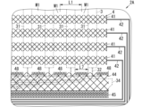
- FIG. 9 the first conductor layer 3 is shown by a dashed line, and the second conductor layer 4 is shown by a solid line. Also, FIG. 10 shows only the second conductor layer 4 in the same range as that shown in FIG. 9. The configuration of the first conductor layer 3 is the same as in embodiment 1 (see FIG. 4).
- the second conductor layer 4 of this embodiment further includes a first ground conductor 48.
- the first ground conductor 48 is located between the first region R1 and the multiple first escape wirings 32 when viewed from the thickness direction of the substrate S1, and is provided in a position facing the area M1 in the Y-axis direction (second direction). Therefore, the electric field generated from the transmission electrode 41 can be absorbed and suppressed by the first ground conductor 48.
- the first ground conductor 48 is provided at a position facing the shield portion 321 of a predetermined first escape wiring 32 having a shield portion 321 and a connecting portion 322 in the Y-axis direction (second direction).
- the first ground conductor 48 is provided between the first region R1 and the shield portion 321.
- all the first escape wirings 32 correspond to the above-mentioned predetermined first escape wirings 32.
- the second conductor layer 4 also includes a plurality of first ground conductors 48.
- the plurality of first ground conductors 48 are provided at positions facing in the Y-axis direction (second direction) an area M1 between any two of the plurality of receiving electrodes 31 adjacent in the X-axis direction (first direction). That is, a plurality of areas M1 are provided, and the first ground conductors 48 are provided at a plurality of positions facing the plurality of areas M1.
- the first ground conductor 48 faces a portion of each of the two shield sections 321 of the two first lead wirings 32 connected to the two adjacent receiving electrodes 31, respectively. More specifically, the first ground conductor 48 faces the first portion 3210 (see FIG. 4) of one shield section 321 and the second portion 3211 (see FIG. 4) of the other shield section 321.
- the length L7 of the first ground conductor 48 in the X-axis direction (first direction) is preferably 50% or more of the length (distance L1) in the X-axis direction (first direction) of the area M1 that faces the first ground conductor 48 in the Y-axis direction (second direction). In this embodiment, the length L7 is 80% or more of the distance L1.
- each of the multiple transmitting electrodes 41 has a mesh shape.
- the first ground conductor 48 is, for example, a ladder wiring in which multiple ladder-shaped structures are arranged in parallel and connected to each other. When viewed from the thickness direction of the substrate S1, the density of the first ground conductor 48 is greater than the density of each of the multiple transmitting electrodes 41. In this embodiment, the definition of the density of the conductor is the same as in the first embodiment. Because the density of the first ground conductor 48 is relatively large, the first ground conductor 48 easily absorbs and suppresses the electric field.
- the first ground conductor 48 may be a solid wiring.
- the second conductor layer 4 includes a second ground conductor 44 electrically connected to a first ground conductor 48.
- the configuration of the second ground conductor 44 is the same as that of the first embodiment.
- the first ground conductor 48 is connected to one end of the second ground conductor 44 on the first region R1 side. More specifically, when viewed from the Z-axis direction, a plurality of recesses are provided at the one end of the second ground conductor 44, and the plurality of first ground conductors 48 are respectively disposed in the plurality of recesses.
- the second ground conductor 44 is provided at a position overlapping the first exit wirings 32 when viewed from the thickness direction of the substrate S1 (see FIG. 9).
- the second ground conductor 44 has a mesh shape. When viewed in the thickness direction of the substrate S1, the density of the first ground conductor 48 is greater than the density of the second ground conductor 44. Because the density of the first ground conductor 48 is relatively large, the first ground conductor 48 is likely to absorb and suppress the electric field. In addition, because the density of the second ground conductor 44 is relatively small, the first extraction wiring 32 that is provided overlapping the second ground conductor 44 can be visually inspected through the second ground conductor 44.
- the second conductor layer 4 also includes a third ground conductor 45 electrically connected to the second ground conductor 44.
- the configuration of the third ground conductor 45 is the same as in the first embodiment.
- the second ground conductor 44 is provided between the first ground conductor 48 and the third ground conductor 45.
- the density of the third ground conductor 45 When viewed in the thickness direction of the substrate S1, the density of the third ground conductor 45 is greater than the density of the second ground conductor 44. In this way, since the density of the third ground conductor 45 is relatively large, the effective area of the third ground conductor 45 (area excluding gaps) can be increased.
- the first conductor layer 3 is shown by a dashed line
- the second conductor layer 4 is shown by a solid line.
- the multiple first ground conductors 48 have different dimensions. The farther a first ground conductor 48 is located from the second region R2 in the X-axis direction (first direction), the longer its length in the Y-axis direction (second direction). The longer the length of a first ground conductor 48 in the Y-axis direction, the larger the area of the first ground conductor 48 can be. For example, in this embodiment, the length of each first ground conductor 48 in the X-axis direction is constant. Therefore, the farther a first ground conductor 48 is located from the second region R2 in the X-axis direction, the larger its area. Furthermore, the larger the area of the first ground conductor 48, the greater the effect of suppressing capacitive coupling tends to be.
- the length of the first ground conductor 48 in the Y-axis direction is increased the farther away from the second region R2 it is, thereby reducing bias in the capacitance of the capacitive coupling. This can further improve the detection accuracy of the capacitance in the touch sensor 1.
- each of the first outgoing wirings 32 extends along the X-axis direction from a position facing the second region R2 and is partially bent in the Y-axis direction.
- each of the second outgoing wirings 42 extends toward the negative side of the Y-axis as it approaches the positive side of the X-axis.
- the second outgoing wirings 42 extend so as to move away from the first outgoing wirings 32 as it approaches the positive side of the X-axis. More specifically, the distance of each of the second outgoing wirings 42 from the first outgoing wirings 32 changes at a position facing the area M1 between the receiving electrodes 31.
- each of the second outgoing wirings 42 is a straight line along the X-axis direction.
- the partial region R3 is a region in which a portion of each of the two or more second escape wirings 42 is provided along the X-axis direction.
- the distance changes to L8, L9, and L10 as one moves toward the positive side of the X-axis.
- the capacitance of the capacitive coupling decreases as the distance in the Y-axis direction between the set of multiple first escape wirings 32 and the partial region R3 increases as the position becomes farther from the second region R2.
- the configuration of the first conductor layer 3 in this embodiment is the same as that in embodiment 3.
- the shape of the multiple second escape wirings 42 in the partial region R3 of the second conductor layer 4 is linear along the X-axis direction. This makes it possible to reduce the area occupied by the multiple second escape wirings 42.
- the second conductor layer 4 does not have a first ground conductor 48, but in this embodiment, as in embodiment 2 or 3, the second conductor layer 4 may have at least one first ground conductor 48.
- each first outgoing wiring 32 has a wiring portion 323 that connects the shield portion 321 and the terminal portion 33, and the wiring portion 323 includes a first wiring portion 3231, a second wiring portion 3232, and a third wiring portion 3233.
- the first wiring portion 3231 extends linearly from the shield portion 321 to the negative side of the Y axis and the negative side of the X axis (diagonally relative to the Y axis and the X axis).
- the second wiring portion 3232 extends linearly from the first wiring portion 3231 along the X axis direction.
- the third wiring portion 3233 extends linearly from the second wiring portion 3232 to the terminal portion 33 to the negative side of the Y axis.
- the second conductor layer 4 does not have a first ground conductor 48, but in this embodiment, as in embodiment 2 or 3, the second conductor layer 4 may have at least one first ground conductor 48.
- the first conductor layer 3 and the second conductor layer 4 do not have to be embedded in the substrate 5 as in FIG. 2.
- the first conductor layer 3 may be laminated on the front surface of the substrate 5 as in FIG. 14, and the second conductor layer 4 may be laminated on the rear surface of the substrate 5 as in FIG. 14.
- the entire substrate 5 corresponds to the insulating layer 51.
- a part of the conductor is removed by etching to form the first conductor layer 3.
- a part of the conductor is removed by etching to form the second conductor layer 4.
- the touch sensor member 2 can be used by attaching the cover member 11 via a transparent adhesive layer.
- the substrate S1 is not limited to being a double-sided substrate, but may be a multi-layer substrate.
- a multi-layer substrate has three or more conductor layers.
- the multi-layer substrate may be configured such that an insulating member including an insulating layer 51 is interposed between the conductor layers.
- the two first outgoing wirings 32a, 32b connected to the two receiving electrodes 31a, 31b at both ends in the X-axis direction, respectively, may not have the second portion 3211 of the shield section 321.
- the second portion 3211 of the first outgoing wiring 32a since no other first outgoing wirings 32 are arranged on the negative side of the first outgoing wiring 32a in the X-axis direction, there is no need for the second portion 3211 of the first outgoing wiring 32a to receive the electric field generated from the transmitting electrode 41, and therefore the second portion 3211 is unnecessary. For the same reason, the second portion 3211 is also unnecessary for the first outgoing wiring 32b.
- some of the first escape wirings 32 may not have the second portion 3211. In other words, it is sufficient that at least one first escape wiring 32 has the second portion 3211.
- each receiving electrode 31, the density of each transmitting electrode 41, and the density of the second ground conductor 44 may be equal. Alternatively, one of these three configurations may have a different density from the other two. Alternatively, each of these three configurations may have a different density.
- the material of the first conductor layer 3 and the second conductor layer 4 is not limited to copper, but may be, for example, silver or a conductive resin.
- the material of the insulating layer 51 is not limited to PET (polyethylene terephthalate) film, but may be, for example, glass fiber or PC (polycarbonate) film.
- the configuration of FIG. 13 may be used as the first conductor layer 3, while the configuration of FIG. 11 may be used as the second conductor layer 4.
- the touch sensor member (2, 2A to 2D) is used in a capacitive touch sensor (1).
- the touch sensor member (2, 2A to 2D) includes a substrate (S1).
- the substrate (S1) has a first conductor layer (3), a second conductor layer (4), and an insulating layer (51).
- the insulating layer (51) is provided between the first conductor layer (3) and the second conductor layer (4).
- the insulating layer (51) has electrical insulation properties.
- the first conductor layer (3) includes a plurality of receiving electrodes (31) and a plurality of first outgoing wirings (32).
- the plurality of receiving electrodes (31) are arranged in a first region (R1) when viewed from the thickness direction of the substrate (S1).
- the plurality of receiving electrodes (31) are arranged in a first direction perpendicular to the thickness direction.
- the plurality of first outgoing wirings (32) are connected to the plurality of receiving electrodes (31).
- the second conductor layer (4) includes a plurality of transmitting electrodes (41) and a plurality of second outgoing wirings (42).
- the plurality of transmitting electrodes (41) are arranged in a first region (R1) when viewed from the thickness direction.
- the plurality of transmitting electrodes (41) are arranged in a second direction.
- the second direction is perpendicular to both the thickness direction and the first direction.
- the plurality of second outgoing wirings (42) are connected to the plurality of transmitting electrodes (41).
- each of the plurality of receiving electrodes (31) is a line extending along the second direction.
- the shape of each of the plurality of transmitting electrodes (41) is a line extending along the first direction.
- each of the plurality of first outgoing wirings (32) is provided from a first peripheral portion of the first region (R1) to a second peripheral portion of the second region (R2).
- the second region (R2) is arranged in the second direction with respect to the first region (R1).
- a predetermined first outgoing wiring (32) among the multiple first outgoing wirings (32) has a shield portion (321) and a connecting portion (322).
- the shield portion (321) faces in the second direction two areas (M1) on both sides of the predetermined receiving electrode (31) connected to the predetermined first outgoing wiring (32).
- the connecting portion (322) has a first end (t1) connected to the predetermined receiving electrode (31) and a second end (t2) connected to the shield portion (321).
- the shield portion (321) extends from the second end (t2) of the connecting portion (322) to both sides in the first direction.
- the electric field generated from a portion of the transmission electrode (41) is absorbed and suppressed by the shield portion (321) of a given first outgoing wiring (32), thereby reducing the possibility that the electric field generated from the portion will be transmitted as noise to another first outgoing wiring (32) adjacent to the given first outgoing wiring (32).
- two or more of the multiple first outgoing wirings (32) are respectively connected to two or more receiving electrodes (31) between two receiving electrodes (31a, 31b) arranged at both ends in the first direction among the multiple receiving electrodes (31).
- Each of the two or more first outgoing wirings (32) corresponds to a predetermined first outgoing wiring (32).
- each of the two or more first escape wirings (32) has a shield portion (321). Therefore, the influence of the electric field (noise) generated from the transmission electrode (41) can be distributed to the two or more first escape wirings (32). This reduces the possibility of noise concentrating on some of the first escape wirings (32). This further improves the detection accuracy of the capacitance in the touch sensor (1).
- the length (L2, L3) in the first direction of the portion of the shield portion (321) between the second end (t2) of the connecting portion (322) and the tip of the shield portion (321) is 25% or more of the length (distance L1) in the first direction of the area (M1) facing the above portion in the second direction.
- the shielding portion (321) is long enough to absorb and suppress the electric field.
- the second conductor layer (4) further includes a ground conductor (first ground conductor 48).
- the ground conductor (first ground conductor 48) is located between the first region (R1) and the first plurality of lead-out wirings (32) as viewed in the thickness direction, and is provided at a position facing the area (M1) in the second direction.
- the electric field generated from the transmitting electrode (41) can be absorbed and suppressed by the ground conductor (first ground conductor 48). This can further improve the detection accuracy of the capacitance in the touch sensor (1).
- the ground conductor (first ground conductor 48) is provided in a position facing the shield portion (321) of the predetermined first lead wiring (32) in the second direction.
- the above configuration makes it possible to reduce noise on the specified first exit wiring (32).
- the second conductor layer (4) includes a plurality of ground conductors (first ground conductor 48) including a ground conductor (first ground conductor 48).
- the plurality of ground conductors (first ground conductor 48) are provided in a position facing in the second direction with respect to an area (M1) between any two of the plurality of receiving electrodes (31) adjacent in the first direction.
- each of the areas (M1) faces a corresponding ground conductor (first ground conductor 48), so the electric field generated by the transmitting electrode (41) can be absorbed and suppressed more effectively.
- the length in the second direction of the multiple ground conductors (first ground conductor 48) is longer the farther the ground conductor (first ground conductor 48) is located from the second region (R2) in the first direction.
- the distance (wiring length) from the second region (R2) increases, the distance over which the transmitting electrode (41) and the receiving electrode (31) run side by side increases, and so the capacitance of the capacitive coupling between the transmitting electrode (41) and the receiving electrode (31) tends to increase. Therefore, in the above configuration, the farther the ground conductor (first ground conductor 48) is from the second region (R2), the longer the length of the ground conductor (first ground conductor 48) in the second direction is, thereby reducing bias in the capacitance of the capacitive coupling. This can further improve the detection accuracy of the capacitance in the touch sensor (1).
- the length (L7) in the first direction of the ground conductor (first ground conductor 48) is 50% or more of the length (distance L1) in the first direction of the area (M1) facing the ground conductor (first ground conductor 48) in the second direction.
- the ground conductor (first ground conductor 48) is long enough to absorb and suppress the electric field.
- the shape of each of the multiple transmission electrodes (41) is mesh-like.
- the density of the ground conductor first ground conductor 48
- the density of the ground conductor (first ground conductor 48) is relatively high, so the ground conductor (first ground conductor 48) easily absorbs and suppresses the electric field.
- the second conductor layer (4) further includes a second ground conductor (44).
- the second ground conductor (44) is electrically connected to the first ground conductor (48) as a ground conductor (first ground conductor 48).
- the second ground conductor (44) is provided at a position overlapping with the multiple first lead-out wirings (32) as viewed from the thickness direction.
- the second ground conductor (44) has a mesh shape. As viewed from the thickness direction, the density of the first ground conductor (48) is greater than the density of the second ground conductor (44).
- the density of the first ground conductor (48) is relatively high, so the first ground conductor (48) can easily absorb and suppress the electric field.
- the second conductor layer (4) further includes a third ground conductor (45).
- the third ground conductor (45) is electrically connected to the second ground conductor (44).
- the second ground conductor (44) is provided between the first ground conductor (48) and the third ground conductor (45). When viewed in the thickness direction, the density of the third ground conductor (45) is greater than the density of the second ground conductor (44).
- the above configuration allows the ground area of the substrate (S1) to be increased compared to a case where the third ground conductor (45) is not provided.
- the density of the third ground conductor (45) is relatively high, the effective area of the third ground conductor (45) can be increased.
- the second conductor layer (4) includes a partial region (R3).
- the partial region (R3) a portion of each of two or more of the second outgoing wirings (42) among the plurality of second outgoing wirings (42) is provided along the first direction.
- the plurality of first outgoing wirings (32) are provided between the first region (R1) and the partial region (R3).
- the distance in the second direction between the set of the plurality of first outgoing wirings (32) and the partial region (R3) is longer the farther the position of the object of distance measurement is from the second region (R2) in the first direction.
- the bias in the capacitance of the capacitive coupling can be reduced by increasing the distance between the first outgoing wiring (32) and the second outgoing wiring (42) the farther away from the second region (R2) the position is. This can further improve the detection accuracy of the capacitance in the touch sensor (1).
- the shape of the connecting portion (322) is linear along the second direction.
- the above configuration can reduce the possibility of capacitive coupling occurring between the connecting portion (322) and the transmitting electrode (41) compared to when the connecting portion (322) has a portion along the first direction.
- the configurations other than the first aspect are not essential for the touch sensor member (2, 2A to 2D) and may be omitted as appropriate.
Landscapes
- Engineering & Computer Science (AREA)
- General Engineering & Computer Science (AREA)
- Theoretical Computer Science (AREA)
- Human Computer Interaction (AREA)
- Physics & Mathematics (AREA)
- General Physics & Mathematics (AREA)
- Position Input By Displaying (AREA)
Priority Applications (2)
| Application Number | Priority Date | Filing Date | Title |
|---|---|---|---|
| CN202380091539.XA CN120530376A (zh) | 2023-01-27 | 2023-12-18 | 触摸屏传感器用构件 |
| JP2024572886A JPWO2024157651A1 (https=) | 2023-01-27 | 2023-12-18 |
Applications Claiming Priority (2)
| Application Number | Priority Date | Filing Date | Title |
|---|---|---|---|
| JP2023-011353 | 2023-01-27 | ||
| JP2023011353 | 2023-01-27 |
Publications (1)
| Publication Number | Publication Date |
|---|---|
| WO2024157651A1 true WO2024157651A1 (ja) | 2024-08-02 |
Family
ID=91970447
Family Applications (1)
| Application Number | Title | Priority Date | Filing Date |
|---|---|---|---|
| PCT/JP2023/045200 Ceased WO2024157651A1 (ja) | 2023-01-27 | 2023-12-18 | タッチセンサ用部材 |
Country Status (3)
| Country | Link |
|---|---|
| JP (1) | JPWO2024157651A1 (https=) |
| CN (1) | CN120530376A (https=) |
| WO (1) | WO2024157651A1 (https=) |
Citations (2)
| Publication number | Priority date | Publication date | Assignee | Title |
|---|---|---|---|---|
| JP2012022427A (ja) * | 2010-07-13 | 2012-02-02 | Rohm Co Ltd | 静電容量式入力装置 |
| JP2016206867A (ja) * | 2015-04-21 | 2016-12-08 | 三菱電機株式会社 | タッチスクリーン、タッチパネル、表示装置及び電子機器 |
-
2023
- 2023-12-18 CN CN202380091539.XA patent/CN120530376A/zh active Pending
- 2023-12-18 JP JP2024572886A patent/JPWO2024157651A1/ja active Pending
- 2023-12-18 WO PCT/JP2023/045200 patent/WO2024157651A1/ja not_active Ceased
Patent Citations (2)
| Publication number | Priority date | Publication date | Assignee | Title |
|---|---|---|---|---|
| JP2012022427A (ja) * | 2010-07-13 | 2012-02-02 | Rohm Co Ltd | 静電容量式入力装置 |
| JP2016206867A (ja) * | 2015-04-21 | 2016-12-08 | 三菱電機株式会社 | タッチスクリーン、タッチパネル、表示装置及び電子機器 |
Also Published As
| Publication number | Publication date |
|---|---|
| CN120530376A (zh) | 2025-08-22 |
| JPWO2024157651A1 (https=) | 2024-08-02 |
Similar Documents
| Publication | Publication Date | Title |
|---|---|---|
| US8681120B2 (en) | Input apparatus and display apparatus | |
| JP2009230735A (ja) | タッチパネル装置 | |
| US10831295B2 (en) | Touch screen, touch panel, display device, and electronic apparatus | |
| TW201104544A (en) | Electrostatic capacitance input device | |
| JP2009169720A (ja) | タッチセンサ | |
| US10025443B2 (en) | Touch panel | |
| JP6233075B2 (ja) | タッチパネルセンサおよびタッチパネルセンサを備える入出力装置 | |
| JP2013008231A (ja) | 静電容量方式にも抵抗膜方式にも対応可能な押圧検出機能を有するタッチパネル | |
| US10949044B1 (en) | Touch structure not affected by changes in capacitance of touch electrode to ground, touch device using same, and method for driving touch structure | |
| JP2010061384A (ja) | 入力装置およびこれを用いた携帯情報処理装置 | |
| CN114550583A (zh) | 显示模组、触控显示模组以及电子设备 | |
| WO2012173068A1 (ja) | タッチパネル | |
| WO2024157651A1 (ja) | タッチセンサ用部材 | |
| JP2016045961A (ja) | タッチパネルセンサおよびタッチ位置検出機能付き表示装置 | |
| JP2015052818A (ja) | タッチパネル | |
| JP6205995B2 (ja) | タッチパネルセンサおよびタッチ位置検出機能付き表示装置 | |
| JP2019087060A (ja) | タッチパネル | |
| JP2016148926A (ja) | タッチパネルセンサ、タッチパネル装置および導電性パターン基板 | |
| CN111065992A (zh) | 触摸传感器 | |
| JP2019032687A (ja) | 入力装置 | |
| CN117321554A (zh) | 触摸传感器 | |
| JP2018112842A (ja) | タッチパネルセンサ及びタッチ位置検出機能付き表示装置 | |
| WO2015025487A1 (ja) | タッチパネル | |
| WO2020022108A1 (ja) | タッチセンサ | |
| CN104881189A (zh) | 静电电容式位置检测装置 |
Legal Events
| Date | Code | Title | Description |
|---|---|---|---|
| 121 | Ep: the epo has been informed by wipo that ep was designated in this application |
Ref document number: 23918606 Country of ref document: EP Kind code of ref document: A1 |
|
| ENP | Entry into the national phase |
Ref document number: 2024572886 Country of ref document: JP Kind code of ref document: A |
|
| WWE | Wipo information: entry into national phase |
Ref document number: 2024572886 Country of ref document: JP |
|
| WWE | Wipo information: entry into national phase |
Ref document number: 202380091539.X Country of ref document: CN |
|
| WWP | Wipo information: published in national office |
Ref document number: 202380091539.X Country of ref document: CN |
|
| NENP | Non-entry into the national phase |
Ref country code: DE |
|
| 122 | Ep: pct application non-entry in european phase |
Ref document number: 23918606 Country of ref document: EP Kind code of ref document: A1 |