WO2024157380A1 - 液化ガス運搬船の消火設備 - Google Patents
液化ガス運搬船の消火設備 Download PDFInfo
- Publication number
- WO2024157380A1 WO2024157380A1 PCT/JP2023/002229 JP2023002229W WO2024157380A1 WO 2024157380 A1 WO2024157380 A1 WO 2024157380A1 JP 2023002229 W JP2023002229 W JP 2023002229W WO 2024157380 A1 WO2024157380 A1 WO 2024157380A1
- Authority
- WO
- WIPO (PCT)
- Prior art keywords
- piping
- area
- fire
- liquefied gas
- fire extinguishing
- Prior art date
- Legal status (The legal status is an assumption and is not a legal conclusion. Google has not performed a legal analysis and makes no representation as to the accuracy of the status listed.)
- Ceased
Links
Images

Classifications
-
- A—HUMAN NECESSITIES
- A62—LIFE-SAVING; FIRE-FIGHTING
- A62C—FIRE-FIGHTING
- A62C3/00—Fire prevention, containment or extinguishing specially adapted for particular objects or places
- A62C3/07—Fire prevention, containment or extinguishing specially adapted for particular objects or places in vehicles, e.g. in road vehicles
- A62C3/10—Fire prevention, containment or extinguishing specially adapted for particular objects or places in vehicles, e.g. in road vehicles in ships
-
- A—HUMAN NECESSITIES
- A62—LIFE-SAVING; FIRE-FIGHTING
- A62C—FIRE-FIGHTING
- A62C35/00—Permanently-installed equipment
- A62C35/02—Permanently-installed equipment with containers for delivering the extinguishing substance
- A62C35/026—Permanently-installed equipment with containers for delivering the extinguishing substance the extinguishing material being put under pressure by means other than pressure gas, e.g. pumps
-
- A—HUMAN NECESSITIES
- A62—LIFE-SAVING; FIRE-FIGHTING
- A62C—FIRE-FIGHTING
- A62C35/00—Permanently-installed equipment
- A62C35/58—Pipe-line systems
- A62C35/68—Details, e.g. of pipes or valve systems
-
- A—HUMAN NECESSITIES
- A62—LIFE-SAVING; FIRE-FIGHTING
- A62C—FIRE-FIGHTING
- A62C99/00—Subject matter not provided for in other groups of this subclass
- A62C99/0009—Methods of extinguishing or preventing the spread of fire by cooling down or suffocating the flames
- A62C99/0072—Methods of extinguishing or preventing the spread of fire by cooling down or suffocating the flames using sprayed or atomised water
-
- B—PERFORMING OPERATIONS; TRANSPORTING
- B63—SHIPS OR OTHER WATERBORNE VESSELS; RELATED EQUIPMENT
- B63B—SHIPS OR OTHER WATERBORNE VESSELS; EQUIPMENT FOR SHIPPING
- B63B25/00—Load-accommodating arrangements, e.g. stowing, trimming; Vessels characterised thereby
- B63B25/02—Load-accommodating arrangements, e.g. stowing, trimming; Vessels characterised thereby for bulk goods
- B63B25/08—Load-accommodating arrangements, e.g. stowing, trimming; Vessels characterised thereby for bulk goods fluid
- B63B25/12—Load-accommodating arrangements, e.g. stowing, trimming; Vessels characterised thereby for bulk goods fluid closed
- B63B25/16—Load-accommodating arrangements, e.g. stowing, trimming; Vessels characterised thereby for bulk goods fluid closed heat-insulated
Definitions
- This disclosure relates to fire extinguishing equipment for liquefied gas carriers.
- Patent Document 1 discloses a liquefied gas carrier.
- Liquefied gas carriers have a cargo area that houses liquefied gas tanks.
- Liquefied gas carriers are equipped with fire extinguishing equipment, which may have piping that passes through the cargo area. In this case, if a fire breaks out in the cargo area, some of the piping for the fire extinguishing equipment may be damaged, making it impossible to continue firefighting activities.
- the present disclosure therefore aims to provide fire protection equipment for liquefied gas carriers that can continue firefighting activities even if part of the piping passing through the cargo area is damaged.
- the fire extinguishing system for a liquefied gas carrier includes a first pipe that passes through a cargo area housing liquefied gas tanks, extends from a stern area aft of the cargo area to a bow area forward of the cargo area, and carries water to be used in the event of a fire, and a second pipe that includes a forward supply port capable of supplying water into the first pipe from a portion of the first pipe forward of the cargo area.
- FIG. 1 is a side view of a liquefied gas carrier equipped with a fire extinguishing system.
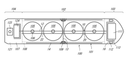
- FIG. 2 is a plan view of a liquefied gas carrier equipped with a fire extinguishing system.
- a liquefied gas carrier 101 on which the fire extinguishing equipment 100 is installed will be described.
- Fig. 1 is a side view of the liquefied gas carrier 101 on which the fire extinguishing equipment 100 is installed.
- Fig. 2 is a plan view of the liquefied gas carrier 101 on which the fire extinguishing equipment 100 is installed. In the following, the right side of the paper in Fig.
- the front direction 2 will be referred to as the "front”
- the left side of the paper will be referred to as the “rear”
- the left-right direction of the paper will be referred to as the “front-rear direction”
- the up-down direction of the paper will be referred to as the "width direction”.
- the liquefied gas carrier 101 has a cargo area 102, a bow area 103, and a stern area 104.
- the cargo area 102 is an area that houses liquefied gas tanks 105.
- the cargo area 102 houses four liquefied gas tanks 105.
- the liquefied gas tanks 105 store liquefied gas such as liquefied hydrogen, liquefied natural gas (LNG), and liquefied petroleum gas (LPG).
- LNG liquefied hydrogen
- LPG liquefied petroleum gas
- a dome 106 that houses various equipment and piping connected to the inside of the liquefied gas tank 105 is located on top of the liquefied gas tank 105.
- internal passages 108 are located at both widthwise ends of the cargo area 102.
- the internal passages 108 are passages that pass through the interior of the ship and extend in the fore-aft direction from the bow area 103 to the stern area 104.
- manifolds 109 are located on the upper deck 107 at both widthwise ends of the cargo area 102.
- the manifolds 109 are connected to external equipment that handles the loading and unloading of liquefied gas, and are located near the center of the cargo area 102 in the fore-aft direction.
- the bow area 103 is an area located forward of the cargo area 102.
- a bow structure 111 is located, including a portion above the upper deck 107.
- the bow structure 111 may include, for example, accommodation areas where the crew work and live.
- lifeboats 112 are located on both sides of the bow structure 111 in the width direction. The part connecting the emergency exit of the bow structure 111 and the lifeboats 112 is used as a meeting place 113 where the crew can gather in case of evacuation.
- the stern area 104 is an area located aft of the cargo area 102.
- the engine room 121 is located in the stern area 104. As shown in FIG. 1, the engine room 121 includes an engine room lower part 122 located below the upper deck 107, and an engine room upper part 123 located above the upper deck 107. Furthermore, the cargo equipment room 124 is located above the upper deck 107 in the stern area 104 and forward of the engine room upper part 123 of the engine room 121.
- the cargo equipment room 124 is where a cargo compressor, cargo pump, or cargo process unit (including one that supplies gas fuel to the engine room) is located.
- the lower surface of the cargo equipment room 124 is located above the upper deck 107, and a gap is formed between the lower surface of the cargo equipment room 124 and the upper deck 107.
- the location of the cargo equipment room 124 is not limited to the above, and in cases where the accommodation area is located in the stern area 104, the cargo equipment room 124 may be located in the cargo area 102 (for example, between the third liquefied gas tank 105 from the front and the fourth liquefied gas tank 105 from the front).
- the fire extinguishing system 100 includes a water spray piping 10, an outboard fire extinguishing piping 20, an inboard fire extinguishing piping 30, and a plurality of pumps 41 to 43. Below, these components will be described in order.
- the water spray piping 10 is a piping through which water flows to be sprayed around the protected object or the fire source in the event of a fire, that is, water to be used in the event of a fire.
- the water spray piping 10 of this embodiment has a water spray nozzle and can spray water onto the protected object.
- the water spray piping 10 passes through the cargo area 102 and extends from the stern area 104 to the bow area 103.
- the water spray piping 10 includes a cargo equipment room spray line 11, a dome spray line 12, a manifold spray line 13, an internal passage spray line 14, a bow structure spray line 15, and an evacuation area spray line 16.
- the cargo equipment room spray line 11 extends along the upper, lower and front surfaces of the cargo equipment room 124, and can spray water onto the upper, lower, front and side surfaces of the cargo equipment room 124.
- the dome spray line 12 extends forward from the cargo equipment room spray line 11 over the dome 106, and can spray water onto the dome 106.
- the manifold spray line 13 branches off from the dome spray line 12 and extends in the width direction, and can spray water onto the manifold 109.
- the internal passage spray line 14 extends forward and rearward from the manifold spray line 13, and can spray water onto the portion of the upper deck 107 corresponding to the internal passage 108.
- the bow structure spray line 15 is connected to the dome spray line 12, extends along the rear surface of the bow structure 111, and can spray water onto the rear surface of the bow structure 111.
- the evacuation area spray line 16 branches off from the bow structure spray line 15 and can spray water onto the lifeboats 112 and assembly area 113.
- each of the lines 11 to 16 of the water spray piping 10 is not limited to the above configuration.
- the dome spray line 12 may be located next to the dome 106, and water may be sprayed onto the dome 106 via a branch pipe extending from the dome spray line 12 toward each dome 106.
- the internal passage spray line 14 may branch off from the water spray piping 10 near the cargo equipment room 124.
- the water spray piping 10 may not include some of the lines 11 to 16.
- the overboard fire piping 20 is a piping through which water flows to be supplied to an overboard fire hydrant in the event of a fire, i.e., water to be used in the event of a fire.
- the overboard fire piping 20 passes through the cargo area 102 and extends from the stern area 104 to the bow area 103.
- the overboard fire piping 20 includes a stern fire line 21 located in the stern area 104, a cargo fire line 22 located in the cargo area 102, and a bow fire line 23 located in the bow area 103.
- the onboard fire piping 30 is a piping through which water flows to be supplied to onboard fire hydrants in the event of a fire, that is, water to be used in the event of a fire.
- the onboard fire piping 30 may be configured to be connected to an outside fire hydrant in the event of a fire so as to supply water to the outside fire hydrant.
- the onboard fire piping 30 is located inside the ship, passes through the cargo area 102, and extends from the stern area 104 to the bow area 103.
- the onboard fire piping 30 in this embodiment passes through the internal passage 108. However, the onboard fire piping 30 may pass outside the internal passage 108.
- the onboard fire extinguishing piping 30 includes a water spray piping forward supply port 31, an outboard fire extinguishing piping forward supply port 32, a water spray piping rear supply port 33, an outboard fire extinguishing piping rear supply port 34, and an intermediate line 35.
- the water spray piping forward supply port 31 is connected to the bow structure spray line 15 of the water spray piping 10.
- the overboard fire extinguishing piping forward supply port 32 is connected to the bow fire extinguishing line 23 of the overboard fire extinguishing piping 20.
- the water spray piping rear supply port 33 is connected to the cargo equipment room spray line 11 of the water spray piping 10.
- the overboard fire extinguishing piping rear supply port 34 is connected to the stern fire extinguishing line 21 of the overboard fire extinguishing piping 20.
- the intermediate line 35 passes through the ship and connects the water spray piping forward supply port 31 and the water spray piping rear supply port 33, as well as the overboard fire extinguishing piping forward supply port 32 and the overboard fire extinguishing piping rear supply port 34.
- the water spray piping rear supply port 33 is located forward of the cargo equipment room 124, but it may be located aft of the cargo equipment room 124.
- the multiple pumps 41 to 43 equipped in the fire extinguishing system 100 include a stern water spray pump 41, a stern fire pump 42, and a bow fire pump 43.
- the fire extinguishing system 100 may be equipped with pumps other than these.
- the stern water spray pump 41 is located in the stern area 104.
- the stern water spray pump 41 is connected to the cargo equipment room spray line 11 of the water spray piping 10, and can supply water into the water spray piping 10 from a portion of the water spray piping 10 rearward of the cargo area 102.
- the stern water spray pump 41 can also supply water into the onboard fire piping 30 through the water spray piping rear supply port 33.
- the stern water spray pump 41 can supply water into the outboard fire piping 20 from a portion of the outboard fire piping 20 rearward of the cargo area 102 through the outboard fire piping rear supply port 34, can supply water into the water spray piping 10 from a portion of the water spray piping 10 forward of the cargo area 102 through the water spray piping front supply port 31, and can supply water into the outboard fire piping 20 from a portion of the outboard fire piping 20 forward of the cargo area 102 through the outboard fire piping front supply port 32.
- the stern fire pump 42 is located in the stern area 104.
- the stern fire pump 42 is connected to the onboard fire piping 30 and supplies water to the onboard fire piping 30. Therefore, the stern fire pump 42 can supply water to the outboard fire piping 20 from the rear of the cargo area 102 of the outboard fire piping 20 via the rear supply port 34 of the outboard fire piping, can supply water to the water spray piping 10 from the rear of the cargo area 102 of the water spray piping 10 via the rear supply port 33 of the water spray piping, can supply water to the water spray piping 10 from the front of the cargo area 102 of the water spray piping 10 via the front supply port 31 of the water spray piping, and can supply water to the outboard fire piping 20 from the front of the cargo area 102 of the outboard fire piping 20 via the front supply port 32 of the outboard fire piping.
- the bow fire pump 43 is located in the bow area 103.
- the bow fire pump 43 is connected to the onboard fire piping 30 and supplies water into the onboard fire piping 30. Therefore, the bow fire pump 43 can supply water into the onboard fire piping 20 from a portion of the onboard fire piping 20 forward of the cargo area 102 via the onboard fire piping forward supply port 32, can supply water into the water spray piping 10 from a portion of the onboard fire piping 20 forward of the cargo area 102 via the water spray piping forward supply port 31, can supply water into the onboard fire piping 20 from a portion of the onboard fire piping 20 rearward of the cargo area 102 via the onboard fire piping rear supply port 34, and can supply water into the water spray piping 10 from a portion of the onboard fire piping 20 rearward of the cargo area 102 via the water spray piping rear supply port 33.
- a pump that supplies water to the water spray piping 10 may be located in the bow area 103.
- water can be supplied into the water spray piping 10 not only from the portion of the water spray piping 10 rearward of the cargo area 102, but also from the portion of the water spray piping 10 forward of the cargo area 102.
- the water spray piping 10 can continue to spray water on the protected object, and firefighting activities can continue.
- water can be supplied into the overboard fire extinguishing piping 20 not only from the portion of the overboard fire extinguishing piping 20 aft of the cargo area 102, but also from the portion of the overboard fire extinguishing piping 20 forward of the cargo area 102.
- the overboard fire extinguishing piping 20 can continue to supply water to each fire hydrant, and firefighting activities can continue.
- the first item disclosed in this specification is a fire extinguishing system for a liquefied gas carrier, comprising: a first pipe that passes through a cargo area accommodating liquefied gas tanks and extends from a stern area rearward of the cargo area to a bow area forward of the cargo area, through which water to be used in the event of a fire flows; and a second pipe that includes a forward supply port capable of supplying water into the first pipe from a portion of the first pipe forward of the cargo area.
- the "water spray piping 10" or the “outboard fire extinguishing piping 20" in the above embodiment corresponds to the "first piping” in the first item
- the "water spray piping forward supply port 31" or the “outboard fire extinguishing piping forward supply port 32" in the above embodiment corresponds to the "forward supply port” in the first item
- the "onboard fire extinguishing piping 30" in the above embodiment corresponds to the "second piping” in the first item.
- water can be supplied into the first piping from a portion of the first piping forward of the cargo area, so that firefighting activities can continue even if part of the first piping is damaged by a fire in the cargo area.
- the second item disclosed in this specification is a fire extinguishing system for a liquefied gas carrier described in the first item, which is equipped with a first pump that supplies water into the first pipe from a portion of the first pipe rearward of the cargo area.
- the first pump can supply water into the first piping from a portion of the first piping rearward of the cargo area.
- the third item disclosed in this specification is the fire extinguishing system for a liquefied gas carrier described in the second item, in which the second piping includes a rear supply port capable of supplying water into the first piping from a portion of the first piping rearward of the cargo area, and an intermediate line that passes through the ship and connects the forward supply port and the rear supply port.
- the "water spray piping 10" in the above embodiment corresponds to the "first piping” in the second item
- the "water spray piping forward supply port 31" and the “water spray piping rearward supply port 33" in the above embodiment correspond to the "forward supply port” and the “rearward supply port” in the third item, respectively.
- the "outboard fire extinguishing piping 20" in the above embodiment corresponds to the "first piping” in the second item
- the "outboard fire extinguishing piping forward supply port 32" and the “outboard fire extinguishing piping rearward supply port 34" in the above embodiment correspond to the "forward supply port” and the "rearward supply port” in the third item, respectively.
- the configuration of the third item even if the first pump is damaged, water can be supplied into the first piping from a portion of the first piping rearward of the cargo area via the rearward supply port.
- the fourth item disclosed in this specification is a fire extinguishing system for a liquefied gas carrier described in the third item, which is located in the bow area and includes a second pump that supplies water into the second pipe.
- the "bow fire pump 43" in the above embodiment corresponds to the "second pump” in the fourth item.
- the configuration of the fourth item even if the first pump is damaged, water can be supplied from the second pump to the first pipe and the second pipe.
- the fifth item disclosed in this specification is a fire extinguishing system for a liquefied gas carrier described in the third item, which is located in the stern area and includes a second pump that supplies water into the second pipe.
- the "stern fire pump 42" in the above embodiment corresponds to the "second pump” in the fifth item.
- water can be supplied from the second pump to the first pipe and the second pipe.
- the sixth item disclosed in this specification is a fire extinguishing system for a liquefied gas carrier described in any one of the first to fifth items, in which the first piping includes a dome spray line that sprays water onto a dome located at the top of the liquefied gas tank.
- the configuration of item 6 makes it possible to protect the area around the dome of the liquefied gas tank in the event of a fire.
- the seventh item disclosed in this specification is a fire extinguishing system for a liquefied gas carrier described in any one of the first to sixth items, in which the first piping includes a bow structure spray line that sprays water onto the outer wall of a bow structure located in the bow area.
- the configuration of item 7 makes it possible to protect the area around the bow structure in the event of a fire.
- the eighth item disclosed in this specification is a fire extinguishing system for a liquefied gas carrier described in any one of the first to seventh items, in which the first piping includes an evacuation area spray line that sprays water onto the lifeboats and assembly points located in the bow area.
- the configuration of item 8 makes it possible to protect the areas around lifeboats and assembly points in the event of a fire.
Landscapes
- Health & Medical Sciences (AREA)
- Public Health (AREA)
- Business, Economics & Management (AREA)
- Emergency Management (AREA)
- Engineering & Computer Science (AREA)
- Ocean & Marine Engineering (AREA)
- Chemical & Material Sciences (AREA)
- Combustion & Propulsion (AREA)
- Mechanical Engineering (AREA)
- Fire-Extinguishing By Fire Departments, And Fire-Extinguishing Equipment And Control Thereof (AREA)
Abstract
Description
以下、実施形態について説明する。はじめに、消火設備100が設置される液化ガス運搬船101について説明する。図1は、消火設備100が設置された液化ガス運搬船101の側面図である。図2は、消火設備100が設置された液化ガス運搬船101の平面図である。なお、以下では、図2における紙面右方を「前方」、紙面左方を「後方」、紙面左右方向を「前後方向」、紙面上下方向を「幅方向」と称する。
続いて、本実施形態に係る消火設備100について説明する。図1に示すように、本実施形態に係る消火設備100は、水噴霧配管10と、船外消火配管20と、船内消火配管30と、複数のポンプ41~43と、を備えている。以下、これらの構成について順に説明する。
本明細書で開示する第1の項目は、液化ガスタンクを収容する貨物エリアを通過し前記貨物エリアよりも後方の船尾エリアから前記貨物エリアよりも前方の船首エリアまで延び、火災時に使用する水が流れる第1配管と、前記第1配管の前記貨物エリアよりも前方の部分から前記第1配管内に水を供給可能な前方供給口を含む第2配管と、を備えている、液化ガス運搬船の消火設備である。
11 貨物機器室噴霧ライン
12 ドーム噴霧ライン
13 マニホールド噴霧ライン
14 内部通路上噴霧ライン
15 船首構造物噴霧ライン
20 船外消火配管
21 船尾消火ライン
22 貨物消火ライン
23 船首消火ライン
30 船内消火配管
31 水噴霧配管前方供給口
32 船外消火配管前方供給口
33 水噴霧配管後方供給口
34 船外消火配管後方供給口
35 中間ライン
41 船尾水噴霧ポンプ
42 船尾消火ポンプ
43 船首消火ポンプ
100 消火設備
101 液化ガス運搬船
102 貨物エリア
103 船首エリア
104 船尾エリア
105 液化ガスタンク
106 ドーム
111 船首構造物
112 救命ボート
113 招集場所
Claims (8)
- 液化ガスタンクを収容する貨物エリアを通過し前記貨物エリアよりも後方の船尾エリアから前記貨物エリアよりも前方の船首エリアまで延び、火災時に使用する水が流れる第1配管と、
前記第1配管の前記貨物エリアよりも前方の部分から前記第1配管内に水を供給可能な前方供給口を含む第2配管と、を備えている、液化ガス運搬船の消火設備。 - 前記第1配管の前記貨物エリアよりも後方の部分から前記第1配管内に水を供給する第1ポンプを備えている、請求項1に記載の液化ガス運搬船の消火設備。
- 前記第2配管は、前記第1配管の前記貨物エリアよりも後方の部分から前記第1配管内に水を供給可能な後方供給口と、船内を通過し前記前方供給口と前記後方供給口とをつなぐ中間ラインと、を含んでいる、請求項2に記載の液化ガス運搬船の消火設備。
- 前記船首エリアに位置し、前記第2配管内に水を供給する第2ポンプを備えている、請求項3に記載の液化ガス運搬船の消火設備。
- 前記船尾エリアに位置し、前記第2配管内に水を供給する第2ポンプを備えている、請求項3に記載の液化ガス運搬船の消火設備。
- 前記第1配管は、前記液化ガスタンクの頂部に位置するドームに水を噴霧するドーム噴霧ラインを含んでいる、請求項1に記載の液化ガス運搬船の消火設備。
- 前記第1配管は、前記船首エリアに位置する船首構造物の外壁に水を噴霧する船首構造物噴霧ラインを含んでいる、請求項1に記載の液化ガス運搬船の消火設備。
- 前記第1配管は、前記船首エリアに位置する救命ボート及び招集場所に水を噴霧する避難エリア噴霧ラインを含んでいる、請求項1に記載の液化ガス運搬船の消火設備。
Priority Applications (4)
| Application Number | Priority Date | Filing Date | Title |
|---|---|---|---|
| PCT/JP2023/002229 WO2024157380A1 (ja) | 2023-01-25 | 2023-01-25 | 液化ガス運搬船の消火設備 |
| JP2024572590A JP7886438B2 (ja) | 2023-01-25 | 2023-01-25 | 液化ガス運搬船の消火設備 |
| CN202380091257.XA CN120513198A (zh) | 2023-01-25 | 2023-01-25 | 液化气运输船的灭火设备 |
| KR1020257021994A KR20250121037A (ko) | 2023-01-25 | 2023-01-25 | 액화 가스 운반선의 소화 설비 |
Applications Claiming Priority (1)
| Application Number | Priority Date | Filing Date | Title |
|---|---|---|---|
| PCT/JP2023/002229 WO2024157380A1 (ja) | 2023-01-25 | 2023-01-25 | 液化ガス運搬船の消火設備 |
Publications (1)
| Publication Number | Publication Date |
|---|---|
| WO2024157380A1 true WO2024157380A1 (ja) | 2024-08-02 |
Family
ID=91969999
Family Applications (1)
| Application Number | Title | Priority Date | Filing Date |
|---|---|---|---|
| PCT/JP2023/002229 Ceased WO2024157380A1 (ja) | 2023-01-25 | 2023-01-25 | 液化ガス運搬船の消火設備 |
Country Status (4)
| Country | Link |
|---|---|
| JP (1) | JP7886438B2 (ja) |
| KR (1) | KR20250121037A (ja) |
| CN (1) | CN120513198A (ja) |
| WO (1) | WO2024157380A1 (ja) |
Citations (5)
| Publication number | Priority date | Publication date | Assignee | Title |
|---|---|---|---|---|
| JP2010076743A (ja) * | 2008-08-29 | 2010-04-08 | Mitsubishi Heavy Ind Ltd | 液化ガス運搬船 |
| JP2013199204A (ja) * | 2012-03-26 | 2013-10-03 | Mitsui Eng & Shipbuild Co Ltd | 船舶 |
| JP2015181546A (ja) * | 2014-03-20 | 2015-10-22 | 三井造船株式会社 | 船舶 |
| JP2019151291A (ja) * | 2018-03-06 | 2019-09-12 | 川崎重工業株式会社 | 液化水素運搬船および船体保護方法 |
| CN113022810A (zh) * | 2021-03-26 | 2021-06-25 | 广州文冲船厂有限责任公司 | 一种防海盗系统和防海盗的方法 |
-
2023
- 2023-01-25 CN CN202380091257.XA patent/CN120513198A/zh active Pending
- 2023-01-25 WO PCT/JP2023/002229 patent/WO2024157380A1/ja not_active Ceased
- 2023-01-25 JP JP2024572590A patent/JP7886438B2/ja active Active
- 2023-01-25 KR KR1020257021994A patent/KR20250121037A/ko active Pending
Patent Citations (5)
| Publication number | Priority date | Publication date | Assignee | Title |
|---|---|---|---|---|
| JP2010076743A (ja) * | 2008-08-29 | 2010-04-08 | Mitsubishi Heavy Ind Ltd | 液化ガス運搬船 |
| JP2013199204A (ja) * | 2012-03-26 | 2013-10-03 | Mitsui Eng & Shipbuild Co Ltd | 船舶 |
| JP2015181546A (ja) * | 2014-03-20 | 2015-10-22 | 三井造船株式会社 | 船舶 |
| JP2019151291A (ja) * | 2018-03-06 | 2019-09-12 | 川崎重工業株式会社 | 液化水素運搬船および船体保護方法 |
| CN113022810A (zh) * | 2021-03-26 | 2021-06-25 | 广州文冲船厂有限责任公司 | 一种防海盗系统和防海盗的方法 |
Also Published As
| Publication number | Publication date |
|---|---|
| JP7886438B2 (ja) | 2026-07-07 |
| KR20250121037A (ko) | 2025-08-11 |
| JPWO2024157380A1 (ja) | 2024-08-02 |
| CN120513198A (zh) | 2025-08-19 |
Similar Documents
| Publication | Publication Date | Title |
|---|---|---|
| CN107848606B (zh) | 具备液化气体储存设备的浮体构造物及其设计方法 | |
| KR102428698B1 (ko) | 액화가스 저장설비를 구비한 부체 구조물 | |
| KR102340890B1 (ko) | 액화 수소 운반선 및 선체 보호 방법 | |
| US11118734B2 (en) | Cold-box system and apparatus for power management aboard ships | |
| US20100139547A1 (en) | Piping structure for oil tanker | |
| KR102327407B1 (ko) | 컨테이너선의 연료가스 공급시스템 | |
| WO2019146087A1 (ja) | 船舶用のlng燃料モジュールと該lng燃料モジュールを搭載した船舶 | |
| KR102327406B1 (ko) | 컨테이너선의 연료가스 공급시스템 | |
| KR102327408B1 (ko) | 컨테이너선의 연료가스 공급시스템 | |
| JP2019108082A (ja) | 洋上浮体式設備、洋上浮体式設備の建造方法、洋上浮体式設備の設計方法、及び洋上浮体式設備への改造方法 | |
| KR102862974B1 (ko) | 선박의 소화 시스템 | |
| KR20250121037A (ko) | 액화 가스 운반선의 소화 설비 | |
| WO2024024481A1 (ja) | 浮体構造物 | |
| KR102677388B1 (ko) | 선박 | |
| JP7754702B2 (ja) | 液化ガス運搬船 | |
| JP7442965B2 (ja) | 船舶の製造方法 | |
| CN211024913U (zh) | Fsru水喷淋系统 | |
| WO2024150271A1 (ja) | 船舶 | |
| KR20260039557A (ko) | 선박 | |
| WO2023199430A1 (ja) | 洋上液化ガス貯蔵設備 | |
| KR20250060274A (ko) | 액화 가스 탱크를 구비한 선박 | |
| JP2023169477A (ja) | 船舶 | |
| WO2025224865A1 (ja) | 液化ガス運搬船 | |
| KR20260009722A (ko) | 선박 | |
| CN121532326A (zh) | 液化气运输船 |
Legal Events
| Date | Code | Title | Description |
|---|---|---|---|
| 121 | Ep: the epo has been informed by wipo that ep was designated in this application |
Ref document number: 23918347 Country of ref document: EP Kind code of ref document: A1 |
|
| WWE | Wipo information: entry into national phase |
Ref document number: 2024572590 Country of ref document: JP |
|
| WWE | Wipo information: entry into national phase |
Ref document number: 1020257021994 Country of ref document: KR |
|
| WWE | Wipo information: entry into national phase |
Ref document number: 202380091257.X Country of ref document: CN |
|
| WWP | Wipo information: published in national office |
Ref document number: 1020257021994 Country of ref document: KR |
|
| WWP | Wipo information: published in national office |
Ref document number: 202380091257.X Country of ref document: CN |
|
| NENP | Non-entry into the national phase |
Ref country code: DE |
|
| 122 | Ep: pct application non-entry in european phase |
Ref document number: 23918347 Country of ref document: EP Kind code of ref document: A1 |