WO2024154652A1 - 異常監視装置およびロボットシステム - Google Patents
異常監視装置およびロボットシステム Download PDFInfo
- Publication number
- WO2024154652A1 WO2024154652A1 PCT/JP2024/000541 JP2024000541W WO2024154652A1 WO 2024154652 A1 WO2024154652 A1 WO 2024154652A1 JP 2024000541 W JP2024000541 W JP 2024000541W WO 2024154652 A1 WO2024154652 A1 WO 2024154652A1
- Authority
- WO
- WIPO (PCT)
- Prior art keywords
- wiring
- joint
- encoder
- robot
- related information
- Prior art date
- Legal status (The legal status is an assumption and is not a legal conclusion. Google has not performed a legal analysis and makes no representation as to the accuracy of the status listed.)
- Ceased
Links
Images

Classifications
-
- B—PERFORMING OPERATIONS; TRANSPORTING
- B25—HAND TOOLS; PORTABLE POWER-DRIVEN TOOLS; MANIPULATORS
- B25J—MANIPULATORS; CHAMBERS PROVIDED WITH MANIPULATION DEVICES
- B25J19/00—Accessories fitted to manipulators, e.g. for monitoring, for viewing; Safety devices combined with or specially adapted for use in connection with manipulators
- B25J19/06—Safety devices
Definitions
- This disclosure relates to an abnormality monitoring device and a robot system.
- JP 2006-220460 A discloses a cable diagnostic device that monitors abnormalities in a power supply cable that supplies welding current to a welding gun attached to a welding robot.
- This cable diagnostic device comprises a pulse signal transmitting section that transmits a pulse signal to the power supply cable, and a reflected pulse signal receiving section that receives a reflected pulse signal from the power supply cable.
- JP 2006-220460 A it is determined whether or not the power supply cable has deteriorated based on the signal level of the reflected pulse signal received by the reflected pulse signal receiving section.
- JP 2006-220460 A deterioration of power supply cables is determined. Meanwhile, in a robot such as that described in JP 2006-220460 A, wiring such as signal lines and power lines is arranged inside the robot. Furthermore, the wiring also deforms as the robot's posture changes, making it easy for wiring abnormalities to occur. In particular, the amount of deformation of wiring is large at the robot's joints, so it is desirable to monitor abnormalities in the wiring located at the robot's joints.
- This disclosure has been made to solve the problems described above, and one objective of this disclosure is to provide an abnormality monitoring device and robot system capable of monitoring abnormalities in wiring located at the joints of a robot.
- the abnormality monitoring device includes a receiving unit that receives wiring-related information about wiring placed in the joints of a robot, and a control unit that monitors whether the wiring is abnormal based on the wiring-related information received by the receiving unit.
- the receiving unit receives wiring-related information about wiring placed at the joints of the robot. This makes it possible to receive wiring-related information from wiring located at the joints of the robot. Then, the control unit monitors whether the wiring is abnormal based on the wiring-related information received by the receiving unit, thereby making it possible to monitor abnormalities in the wiring located at the joints of the robot.
- a robot system includes a robot including joints, and an abnormality monitoring device that monitors abnormalities in wiring arranged at the joints of the robot.
- the abnormality monitoring device includes a receiving unit that receives wiring-related information about the wiring, and a control unit that monitors whether the wiring is abnormal based on the wiring-related information received by the receiving unit.
- the receiving unit receives wiring-related information about wiring placed at the joints of the robot. This makes it possible to receive wiring-related information from wiring located at the joints of the robot. Then, the control unit monitors whether the wiring is abnormal based on the wiring-related information received by the receiving unit, thereby providing a robot system capable of monitoring abnormalities in the wiring located at the joints of the robot.
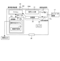
- FIG. 1 is a block diagram of a robot system according to a first embodiment.
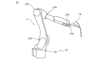
- FIG. 1 is a diagram showing a robot according to a first embodiment.
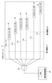
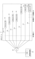
- 3A and 3B are diagrams for explaining an encoder and encoder wiring according to the first embodiment.
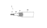
- 5A and 5B are diagrams illustrating encoder wiring and shielding wires according to the first embodiment.
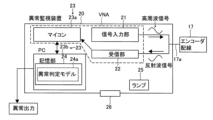
- 1 is a block diagram of an abnormality monitoring device according to a first embodiment.
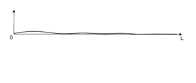
- FIG. 13 is a diagram showing a reflected wave signal when the robot is in a home posture state.
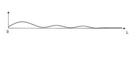
- FIG. 13 is a diagram showing a reflected wave signal when the robot's posture is changed from the home posture.
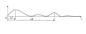
- FIG. 13 is a diagram illustrating a reflected wave signal when an abnormality occurs in the shielded wire.
- FIG. 11 is a block diagram of an abnormality monitoring device according to a second embodiment. 13 is a diagram for explaining an encoder and encoder wiring according to a modified example.
- the robot system 100 includes a robot 10 and an abnormality monitoring device 20.
- the robot system 100 is disposed in a facility 1 such as a factory.
- the facility 1 is provided with an alarm unit 2 that issues an alarm.
- the robot system 100 includes a robot 10, a robot controller 12, and a teaching pendant 13.
- the robot 10 includes a robot arm 11, an end effector 14, a drive unit 15, and an encoder 16.
- the robot 10 is, for example, a vertical articulated robot.
- the end effector 14 is attached to the tip of the robot arm 11.
- the end effector 14 is, for example, a torch or servo gun for welding.
- the robot 10 includes a six-axis vertical articulated robot in which, from the base end to the tip end, there are arranged a first joint JT1, a second joint JT2, a third joint JT3, which in particular rotate in a torsional manner, and a fourth joint JT4, a fifth joint JT5, and a sixth joint JT6, which in particular rotate in a torsional manner.
- the first joint JT1 to the sixth joint JT6 are collectively referred to as joints JT.
- the number of joints JT may be other than six.
- each joint JT includes a drive unit 15.
- the drive unit 15 is, for example, a servo motor.
- the drive unit 15 drives each joint JT.
- the robot controller 12 controls the operation of the robot arm 11 based on the operation taught by the operator using the teaching pendant 13.
- the robot controller 12 includes a main control unit 12a and a servo control unit 12b.
- the servo control unit 12b controls the operation of the drive unit 15 based on commands from the main control unit 12a.
- the teaching pendant 13 accepts operations to teach the robot 10 how to operate.
- the teaching pendant 13 includes a display unit 13a on which an operating program and the like are displayed.
- each joint JT includes an encoder 16 that detects the rotational position of each joint JT.
- the encoder 16 is disposed at each joint JT.
- Encoder wiring 17 is connected to the encoder 16.
- the encoder wiring 17 transmits a signal related to the rotational position of each joint JT detected by the encoder 16 to the robot controller 12.
- the encoder wiring 17 is an example of wiring.
- the encoder wiring 17 is included in cable C.
- a shield wire 18 is arranged to surround the encoder wiring 17.
- the shield wire 18 is formed, for example, by braiding metal such as copper or aluminum.
- the shield wire 18 has the function of suppressing the intrusion of noise into the encoder wiring 17 and suppressing the emission of electromagnetic waves from the encoder wiring 17.
- An insulating layer 19a is arranged between the encoder wiring 17 and the shield wire 18.
- an insulating layer 19b is arranged to surround the shield wire 18.
- Cable C may be a multi-core cable.
- the abnormality monitoring device 20 includes a signal input unit 21, a receiving unit 22, a control unit 23, a memory unit 24, and a lamp 25.
- the signal input unit 21 inputs a signal to the encoder wiring 17.
- the signal input unit 21 is a pulse generator that generates high frequency and inputs a high frequency pulse to the encoder wiring 17.
- a switching circuit 30 is connected to the base end side of the encoder wiring 17.
- the switching circuit 30 is, for example, a rotary switch.
- the encoder wiring 17 is arranged for each joint JT. These encoder wirings 17 are respectively referred to as encoder wirings 17a, 17b, 17c, 17d, 17e, and 17f.
- the encoder wirings 17a to 17f are each connected to the switching circuit 30.
- the switching circuit 30 connects any one of the encoder wirings 17a to 17f to a VNA of the abnormality monitoring device 20, which will be described later. Note that in the example shown in FIG. 3, one switching circuit 30 and one VNA of the abnormality monitoring device 20 are arranged for six joints JT.
- the receiver 22 of the abnormality monitoring device 20 receives wiring-related information of the encoder wiring 17 via the switching circuit 30. Specifically, the receiver 22 receives a reflected wave signal of the signal input to the encoder wiring 17 as the wiring-related information. If an abnormality occurs in the encoder wiring 17, the signal input to the encoder wiring 17 is reflected at the abnormal part of the encoder wiring 17. The receiver 22 receives a reflected wave signal that is a signal reflected from the abnormal part. The presence or absence of an abnormality in the encoder wiring 17 is detected based on the magnitude of the reflected wave signal and the time it takes for the reflected wave signal to return. This method of detecting the presence or absence of an abnormality is called the TDR (time domain reflectometry) method.
- TDR time domain reflectometry
- the control unit 23 monitors whether or not the encoder wiring 17 is abnormal based on the reflected wave signal received by the receiving unit 22.
- the control unit 23 includes a microcomputer 23a and a personal computer (PC) 23b.
- a VNA vector network analyzer
- the microcomputer 23a performs a fast Fourier transform (FFT) on the reflected wave signal received by the receiving unit 22.
- the microcomputer 23a calculates the magnitude of the reflected wave signal and the time until the reflected wave signal returns.
- the PC 23b monitors whether or not the shielded wire 18 is abnormal based on the magnitude of the reflected wave signal calculated by the microcomputer 23a and the time until the reflected wave signal returns.
- the PC 23b is an example of a judgment control unit.
- FIG. 6 shows the reflected wave signal in the home posture state of the robot 10 when no abnormality occurs in the encoder wiring 17.
- the vertical axis of FIG. 6, FIG. 7, and FIG. 8 represents the magnitude of the reflected wave signal
- the horizontal axis represents the length of the encoder wiring 17.
- the home posture state of the robot 10 is the basic posture of the robot 10. In the home posture state of the robot 10, the change in the intensity
- FIG. 7 shows the reflected wave signal in a state in which the posture of the robot 10 is changed from the home posture when no abnormality occurs in the encoder wiring 17.
- the change in the intensity of the reflected wave signal is larger than the intensity of the reflected wave signal in the home posture.
- FIG. 8 shows the reflected wave signal in a state in which the robot 10 is in the home posture state and an abnormality occurs in the encoder wiring 17 at the positions of distances L1 and L2. At distances L1 and L2, the reflected wave signal is larger than the reflected wave signal in FIG. 6.
- Distances L1 and L2 refer to the distances from the point where the abnormality monitoring device 20 is connected to the encoder wiring 17.
- the control unit 23 monitors whether the encoder wiring 17 is abnormal based on the reflected wave signal from the encoder wiring 17 located at the first joint JT1 that rotates torsionally and the fourth joint JT4 that rotates torsionally.
- the control unit 23 monitors the reflected wave signal from the distance L corresponding to each of the first joint JT1 and the fourth joint JT4. All of the encoder wirings 17a to 17f extending from the encoder 16 located at all joints JT from the first joint JT1 to the sixth joint JT6 are arranged at the first joint JT1. This allows the control unit 23 to monitor the reflected wave signal from all of the encoder wirings 17a to 17f located at the first joint JT1.
- the fourth joint JT4 is arranged with the encoder wirings 17e and 17f extending from the encoders 16 located at the fifth joint JT5 and the sixth joint JT6, respectively.
- This allows the control unit 23 to monitor the reflected wave signals from the encoder wires 17e and 17f located at the fourth joint JT4. That is, it is possible to monitor the encoder wires 17e and 17f for abnormalities at the fourth joint JT4.
- the drive unit 15 is disposed on the rotating side of the parts connected by the first joint JT1, so the encoder wire 17 is twisted at the first joint JT1.
- PC 23b determines whether or not the encoder wiring 17 is abnormal based on the reflected wave signal of the encoder wiring 17 when it is normal and the current reflected wave signal of the encoder wiring 17. For example, PC 23b calculates a difference value between the reflected wave signal of the encoder wiring 17 when it is normal and the current reflected wave signal of the encoder wiring 17. PC 23b determines that the encoder wiring 17 is abnormal based on the difference value.
- the storage unit 24 stores an abnormality determination model 24a generated by machine learning based on the reflected wave signal in each of a plurality of postures of the robot 10 having a normal encoder wiring 17.
- AI artificial intelligence
- a neural network such as an autoencoder is used as the AI.
- An autoencoder means an algorithm that compresses input data once, leaves only important features, and then restores the data to the original dimensions.
- the input data is the reflected wave signal in each of a plurality of postures of the robot 10 having a normal encoder wiring 17.
- the abnormality determination model 24a is generated in advance by a PC or the like that is arranged separately from the abnormality monitoring device 20.
- the generated abnormality determination model 24a is stored in the storage unit 24 of the abnormality monitoring device 20.
- the data input to generate the abnormality determination model 24a also includes the angle values of each joint JT of the robot 10.
- the angle values of each joint JT of the robot 10 are detection values detected by the encoder 16 of each joint JT. This generates an abnormality determination model 24a that corresponds to each of the multiple postures of the robot 10.
- the PC 23b also estimates the reflected wave signal in the current posture of the robot 10 based on the abnormality determination model 24a. Specifically, the PC 23b inputs the angle values of each joint JT in the current posture of the robot 10 to the abnormality determination model 24a. As a result, the reflected wave signal in the current posture of the robot 10 is estimated by the abnormality determination model 24a. The PC 23b then compares the estimated reflected wave signal with the actual reflected wave signal in the current posture of the robot 10 to determine whether the encoder wiring 17 is abnormal or not. If no abnormality occurs in the encoder wiring 17, the difference between the estimated reflected wave signal and the actual reflected wave signal is small, so the difference value is equal to or smaller than a predetermined threshold value.
- the PC 23b determines that the encoder wiring 17 is not abnormal. If an abnormality occurs in the encoder wiring 17, the difference between the estimated reflected wave signal and the actual reflected wave signal becomes large, and the difference value exceeds a predetermined threshold value. For this reason, the PC 23b determines that the encoder wiring 17 is abnormal.
- the necessity of machine learning to accurately identify anomalies in the encoder wiring 17 will be explained. Even if there is no abnormality in the encoder wiring 17, the impedance of the encoder wiring 17 becomes locally discontinuous at the part where the multiple encoder wirings 17 branch out, at the part where the encoder wiring 17 is clamped, at the part where the encoder wiring 17 is bent, and at the part where the encoder wiring 17 is twisted.
- the encoder wiring 17 rotates in a bending rotation, a twisting rotation, or a compound rotation of bending rotation and twisting rotation with the rotation of the joint JT. In particular, when the encoder wiring 17 rotates in a compound rotation, the impedance of the encoder wiring 17 is likely to become locally discontinuous.
- the detection value detected by the encoder 16 of each joint JT differs depending on the posture of the robot 10 when it is stopped. Therefore, it is necessary to change the posture of the robot 10 and store all the detection values of the encoder 16 of each joint JT in each posture when the robot 10 is stopped and the data of the reflected wave signal generated in each posture. It is difficult to analyze the detection values of the encoder 16 of each joint JT and the reflected wave data stored manually. Therefore, by analyzing the patterns of the detection values of the encoder 16 of each joint JT and the reflected wave signal data stored by machine learning and generating an abnormality determination model 24a from the analyzed pattern, it becomes possible to accurately and precisely distinguish the reflected wave signal caused by the abnormality.
- the memory unit 24 is arranged inside the PC 23b, but the memory unit 24 may be arranged outside the PC 23b.
- an external connection terminal 26 may be arranged in the abnormality monitoring device 20, and information required to determine an abnormality in the encoder wiring 17 may be input and output via the external connection terminal 26.
- Information required to determine an abnormality is, for example, the rotation angle of each joint JT of the robot 10.
- the PC 23b outputs the result of the determination as to whether the encoder wiring 17 is abnormal to the notification unit. For example, if the encoder wiring 17 is abnormal, the PC 23b controls the lamp 25 arranged on the abnormality monitoring device 20 to light up. As shown in FIG. 1, the PC 23b outputs a signal to the robot controller 12 indicating that the encoder wiring 17 is abnormal. The robot controller 12 controls the display unit 13a of the teaching pendant 13 to display that the encoder wiring 17 is abnormal. The PC 23b also outputs to the notification unit 2 arranged in the facility 1 in which the robot system 100 is arranged that the encoder wiring 17 is abnormal. The lamp 25 and the display unit 13a of the teaching pendant 13 are examples of a notification unit.
- the receiving unit 22 receives the wiring-related information of the encoder wiring 17 arranged at the joint JT of the robot 10. This makes it possible to receive the wiring-related information from the encoder wiring 17 located at the joint JT of the robot 10. Then, the control unit 23 monitors whether the encoder wiring 17 is abnormal based on the wiring-related information received by the receiving unit 22, thereby making it possible to monitor for abnormalities in the encoder wiring 17 located at the joint JT of the robot 10.
- the abnormality monitoring device 20 includes a signal input unit 21 that inputs a signal to the encoder wiring 17.
- the receiver unit 22 receives the reflected wave signal of the signal input to the encoder wiring 17 as a reflected wave signal, and the control unit 23 monitors whether or not the encoder wiring 17 is abnormal based on the received reflected wave signal. As a result, a reflected wave signal reflecting the abnormality is reflected from the location where the abnormality has occurred in the shield wire 18, making it possible to identify the location where the abnormality has occurred in the shield wire 18.
- the robot 10 includes a first joint JT1 that rotates in a torsional manner and a fourth joint JT4 that rotates in a torsional manner.
- the control unit 23 monitors whether the encoder wiring 17 is abnormal based on the reflected wave signal from the encoder wiring 17 located at the first joint JT1 and the fourth joint JT4.
- the first joint JT1 that rotates in a torsional manner and the fourth joint JT4 that rotates in a torsional manner may rotate frequently.
- the encoder wiring 17 is likely to be abnormal at the first joint JT1 and the fourth joint JT4.
- control unit 23 monitors whether the encoder wiring 17 is abnormal based on the reflected wave signal from the encoder wiring 17 located at the first joint JT1 and the fourth joint JT4, thereby making it possible to appropriately monitor abnormalities in the portion of the encoder wiring 17 located at the joint JT where abnormalities are likely to occur.
- PC23b determines whether or not the encoder wiring 17 is abnormal based on the reflected wave signal of the encoder wiring 17 when it is normal and the current reflected wave signal of the encoder wiring 17. As a result, since the reflected wave signal of the encoder wiring 17 when it is abnormal is different from the reflected wave signal of the encoder wiring 17 when it is normal, it can be easily determined whether or not the encoder wiring 17 is abnormal based on the reflected wave signal of the encoder wiring 17 when it is normal and the current reflected wave signal of the encoder wiring 17.
- the abnormality monitoring device 20 includes a storage unit 24 that stores an abnormality determination model 24a generated by machine learning based on the reflected wave signal in each of a plurality of postures of the robot 10 having a normal encoder wiring 17.
- the PC 23b estimates the reflected wave signal in the current posture of the robot 10 based on the abnormality determination model 24a, and judges whether the encoder wiring 17 is abnormal by comparing the estimated reflected wave signal with the actual reflected wave signal in the current posture of the robot 10. Due to the influence of noise, etc., it may be difficult for an operator to judge whether the encoder wiring 17 is abnormal even if the operator visually recognizes the reflected wave signal.
- the PC 23b judges whether the encoder wiring 17 is abnormal based on the abnormality determination model 24a generated by machine learning, so that it is possible to easily judge whether the encoder wiring 17 is abnormal even when the operator has difficulty judging whether the encoder wiring 17 is abnormal.
- the PC 23b of the control unit 23 outputs the result of the determination as to whether or not the encoder wiring 17 is abnormal to the lamp 25, the display unit 13a of the teaching pendant 13, and the notification unit 2 arranged on the equipment 1. This allows the worker to easily recognize that the encoder wiring 17 is abnormal based on the notification by the lamp 25, the display unit 13a of the teaching pendant 13, and the notification unit 2 arranged on the equipment 1.
- a machine learning unit 121 is provided in an anomaly monitoring device 120.
- the abnormality monitoring device 120 includes a machine learning unit 121 that generates an abnormality determination model 24a by executing machine learning based on the reflected wave signal.
- the machine learning unit 121 updates the abnormality determination model 24a by executing machine learning at predetermined intervals.
- the storage unit 24 stores the updated abnormality determination model 24a.
- machine learning software as the machine learning unit 121 is installed in the storage unit 24 of the PC 23b.
- the machine learning unit 121 automatically performs machine learning based on the reflected wave signal.
- the machine learning unit 121 performs machine learning based on the reflected wave signal generated when the posture of the robot 10 is changed multiple times. At this time, the encoder wiring 17 is considered to be normal.
- the machine learning software can be installed on the abnormality monitoring device 120 that is attached to a new robot 10, and can also be installed on the abnormality monitoring device 120 that has already been shipped. In other words, the machine learning unit 121 can be retrofitted.
- the timing of the machine learning by the machine learning unit 121 is, for example, as follows.
- the machine learning unit 121 When the robot 10 is started for the first time, the machine learning unit 121 generates the abnormality determination model 24a by machine learning based on the reflected wave signal.
- the program for driving the machine learning unit 121 when the program for driving the machine learning unit 121 is changed, the machine learning unit 121 generates the abnormality determination model 24a based on the reflected wave signal.
- the encoder wiring 17 is replaced, the machine learning unit 121 generates the abnormality determination model 24a based on the reflected wave signal.
- the machine learning unit 121 calibrates the abnormality determination model 24a.
- the machine learning unit 121 executes machine learning individually for the robot 10 to which the abnormality monitoring device 120 is attached. In other words, the generated abnormality determination model 24a differs from one robot 10 to another.
- the anomaly monitoring device 120 includes a machine learning unit 121 that generates an anomaly determination model 24a by executing machine learning based on the reflected wave signal.
- the machine learning unit 121 updates the anomaly determination model 24a by executing machine learning at predetermined intervals, and the storage unit 24 stores the updated anomaly determination model 24a.
- the anomaly monitoring device 120 since the anomaly monitoring device 120 includes the machine learning unit 121, the anomaly monitoring device 120 can generate an anomaly determination model 24a even for a robot 10 that has already been shipped, and therefore it is possible to monitor for anomalies in the encoder wiring 17 arranged on a robot 10 that has already been shipped.
- the wiring-related information includes information other than the reflected wave signal from the encoder wiring 17.
- the wiring-related information includes at least one of the operation time of the robot 10, the total rotation amount of the joint JT, the maximum speed of the joint JT, and the maximum acceleration/deceleration of the joint JT, in addition to the reflected wave signal.
- the wiring-related information includes the reflected wave signal, the operation time of the robot 10, the total rotation amount of the joint JT, the maximum speed of the joint JT, and the maximum acceleration/deceleration of the joint JT.
- the PC 23b uses the operation time of the robot 10, the total rotation amount of the joint JT, the maximum speed of the joint JT, and the maximum acceleration/deceleration of the joint JT as reference data for judgment. Even if the encoder wiring 17 is judged not to be abnormal based on the abnormality judgment model 24a, the PC 23b may judge that the encoder wiring 17 is abnormal based on the operation time of the robot 10, the total rotation amount of the joint JT, the maximum speed of the joint JT, and the maximum acceleration/deceleration of the joint JT. For example, if the operating time of the robot 10 exceeds a predetermined time, the PC 23b determines that the encoder wiring 17 is abnormal even if the encoder wiring 17 is determined not to be abnormal based on the abnormality determination model 24a.
- the wiring-related information includes, in addition to the reflected wave signal, at least one of the operation time of the robot 10, the total rotation amount of the joint JT, the maximum speed of the joint JT, and the maximum acceleration/deceleration of the joint JT. This allows an abnormality to be determined based on at least one of the operation time of the robot 10, the total rotation amount of the joint JT, the maximum speed of the joint JT, and the maximum acceleration/deceleration of the joint JT in addition to the reflected wave signal, thereby improving the accuracy of abnormality determination.
- the encoder wiring 17 is monitored for abnormality, but the present disclosure is not limited to this.
- the present disclosure may be applied to monitor abnormalities in power lines other than the encoder wiring 17 arranged at the joint JT of the robot 10.
- the encoder wiring 17 is monitored for abnormality based on the reflected wave signal of the signal input to the encoder wiring 17, but the present disclosure is not limited to this.
- the reflected wave signal of the signal input to the shield line 18 may be used as the wiring-related information of the encoder wiring 17.
- the encoder wiring 17 may be monitored for abnormality based on the reflected wave signal of the signal input to the shield line 18.
- the shield line 18 is arranged so as to surround the encoder wiring 17. An abnormality occurs in the shield line 18 arranged so as to surround the encoder wiring 17 before the encoder wiring 17.
- an abnormality in the encoder wiring 17 can be predicted before an abnormality occurs in the encoder wiring 17.
- a wiring other than the shield line 18 may be arranged around the encoder wiring 17, and the encoder wiring 17 may be monitored for abnormality based on the reflected wave signal of the signal input to this wiring.
- the TDR method is used to detect the presence or absence of an abnormality in the encoder wiring 17, but the present disclosure is not limited to this.
- a method other than the TDR method may be used to detect the presence or absence of an abnormality in the encoder wiring 17.
- the robot 10 was a six-axis vertical articulated robot, but the present disclosure is not limited to this.
- the present disclosure can also be applied to horizontal articulated robots other than six-axis vertical articulated robots.
- the encoder wiring 17 is monitored for abnormalities based on reflected wave signals from the encoder wiring 17 located at the first joint JT1 that rotates torsionally and the fourth joint JT4 that rotates torsionally, but the present disclosure is not limited to this.
- the encoder wiring 17 may be monitored for abnormalities based on reflected wave signals from the encoder wiring 17 located at the first joint JT1, the fifth joint JT5, and the sixth joint JT6.
- all of the encoder wirings 17a to 17f are disposed at the first joint JT1.
- the encoder wiring 17g extending from the end effector 14 is disposed at the fifth joint JT5 and the sixth joint JT6.
- PC 23b determines whether or not the encoder wiring 17 is abnormal based on the abnormality determination model 24a generated by machine learning, but the present disclosure is not limited to this.
- PC 23b may determine whether or not the encoder wiring 17 is abnormal based on whether or not the difference value between the normal reflected wave signal and the current reflected wave signal exceeds a predetermined threshold value, without using the abnormality determination model 24a.
- one VNA of the abnormality monitoring device 20 is arranged for six joints JT, but the present disclosure is not limited to this.
- a VNA of the abnormality monitoring device 20 may be arranged for each of multiple joints JT.
- the switching circuit 30 is not required.
- one VNA of the abnormality monitoring device 20 for six joints JT one may be arranged for every two or three joints JT. In this case, multiple VNAs will be arranged.
- the switching circuit 30 is connected to the base end side of the encoder wiring 17, but the present disclosure is not limited to this.
- a wiring may be branched from a predetermined position of the encoder wiring 17 of each joint JT, and the switching circuit 30 may be connected to the tip of this wiring.
- the PC 23b uses the operating time of the robot 10, the total rotation amount of the joint JT, the maximum speed of the joint JT, and the maximum acceleration/deceleration of the joint JT as reference data for the judgment, in addition to judging whether the encoder wiring 17 is abnormal based on the abnormality judgment model 24a. That is, in the third embodiment, the operating time of the robot 10, the total rotation amount of the joint JT, the maximum speed of the joint JT, and the maximum acceleration/deceleration of the joint JT are not used in generating the abnormality judgment model 24a.
- the operating time of the robot 10 for example, in addition to the reflected wave signal and the detection value detected by the encoder 16 of each joint JT, the operating time of the robot 10, the total rotation amount of the joint JT, the maximum speed of the joint JT, and the maximum acceleration/deceleration of the joint JT may be used in generating the abnormality judgment model 24a. This can improve the accuracy of the judgment of the abnormality judgment model 24a.
- circuits or processing circuits including general purpose processors, special purpose processors, integrated circuits, ASICs (Application Specific Integrated Circuits), conventional circuits, and/or combinations thereof, configured or programmed to perform the disclosed functions.
- Processors are considered processing circuits or circuits because they include transistors and other circuits.
- a circuit, unit, or means is hardware that performs the recited functions or hardware that is programmed to perform the recited functions.
- the hardware may be hardware disclosed herein or other known hardware that is programmed or configured to perform the recited functions. Where the hardware is a processor, which is considered a type of circuit, the circuit, means, or unit is a combination of hardware and software, and the software is used to configure the hardware and/or the processor.
- (Aspect 1) a receiving unit that receives wiring-related information of wiring to be placed in a joint of the robot; a control unit that monitors whether or not the wiring is abnormal based on the wiring-related information received by the receiving unit.
- a signal input unit for inputting a signal to the wiring receives, as the wiring-related information, a reflected wave signal of a signal input to the wiring, 2.
- the abnormality monitoring device monitors whether or not the wiring is abnormal based on the received reflected wave signal.
- the joint includes an encoder for detecting a rotational position of the joint;
- the abnormality monitoring device according to aspect 1 or 2, wherein the wiring includes an encoder wiring connected to the encoder.
- the joint includes a torsion-rotation joint, The abnormality monitoring device according to aspect 3, wherein the control unit monitors whether or not the encoder wiring is abnormal based on the wiring-related information from the wiring arranged in the torsionally rotating joint.
- control unit includes a determination control unit that determines whether or not the wiring is abnormal based on the wiring-related information when the wiring is normal and the wiring-related information of the current wiring.
- (Aspect 6) a storage unit that stores an abnormality determination model generated by machine learning based on the wiring-related information for each of a plurality of postures of the robot having the wiring that is normal;
- the determination control unit is estimating the wiring-related information in a current posture of the robot based on the abnormality determination model; 6.
- the abnormality monitoring device according to aspect 5, wherein the estimated wiring-related information is compared with the actual wiring-related information in the current posture of the robot to determine whether or not the wiring is abnormal.
- (Aspect 7) a machine learning unit that generates the abnormality determination model by executing machine learning based on the wiring-related information; the machine learning unit updates the anomaly determination model by executing the machine learning at predetermined intervals; 7.
- the anomaly monitoring device according to claim 6, wherein the storage unit stores the updated anomaly determination model.
- a signal input unit for inputting a signal to the wiring The abnormality monitoring device according to aspect 6 or 7, wherein the wiring-related information includes a reflected wave signal of a signal input to the wiring.
- a robot including a joint; an abnormality monitoring device for monitoring abnormalities in wiring arranged at the joints of the robot,
- the abnormality monitoring device includes: A receiving unit for receiving wiring-related information of the wiring; a control unit that monitors whether or not the wiring is abnormal based on the wiring-related information received by the receiving unit.
Landscapes
- Engineering & Computer Science (AREA)
- Robotics (AREA)
- Mechanical Engineering (AREA)
- Manipulator (AREA)
Abstract
Description
以下、本開示を具体化した本開示の第1実施形態を図面に基づいて説明する。
受信部22は、ロボット10の関節JTに配置されるエンコーダ配線17の配線関連情報を受信する。これにより、ロボット10の関節JTに位置するエンコーダ配線17からの配線関連情報を受信することができる。そして、制御部23が、受信部22により受信された配線関連情報に基づいて、エンコーダ配線17が異常であるか否かを監視することにより、ロボット10の関節JTに位置しているエンコーダ配線17の異常を監視することができる。
図9を参照して、本開示の第2実施形態を説明する。なお、第2実施形態では、異常監視装置120に機械学習部121が備えられている。
異常監視装置120は、反射波信号に基づく機械学習を実行することにより異常判定モデル24aを生成する機械学習部121を備える。機械学習部121は、所定の期間ごとに機械学習を実行することにより異常判定モデル24aを更新し、記憶部24は、更新された異常判定モデル24aを記憶する。これにより、異常監視装置120が機械学習部121を備えることによって、既に出荷されたロボット10に対しても異常監視装置120により異常判定モデル24aを生成することができるので、既に出荷されたロボット10に配置されるエンコーダ配線17に対しても異常を監視することができる。
本開示の第3実施形態を説明する。なお、第3実施形態では、配線関連情報は、エンコーダ配線17からの反射波信号以外の情報を含む。
配線関連情報は、反射波信号に加えて、ロボット10の稼働時間、関節JTの総回転量、関節JTの最高速度、および、関節JTの最大加減速度のうちの少なくとも1つを含む。これにより、反射波信号に加えて、ロボット10の稼働時間、関節JTの総回転量、関節JTの最高速度、および、関節JTの最大加減速度のうちの少なくとも1つに基づいて異常が判定されるので、異常を判定の精度を向上できる。
なお、今回開示された実施形態は、すべての点で例示であって制限的なものではないと考えられるべきである。本開示の範囲は、上記した実施形態の説明ではなく請求の範囲によって示され、さらに請求の範囲と均等の意味および範囲内でのすべての変更(変形例)が含まれる。
上記した例示的な実施形態は、以下の態様の具体例であることが当業者により理解される。
ロボットの関節に配置される配線の配線関連情報を受信する受信部と、
前記受信部により受信された前記配線関連情報に基づいて、前記配線が異常であるか否かを監視する制御部と、を備える、異常監視装置。
前記配線に信号を入力する信号入力部を備え、
前記受信部は、前記配線関連情報として、前記配線に入力された信号の反射波信号を受信し、
前記制御部は、受信された前記反射波信号に基づいて、前記配線が異常であるか否かを監視する、態様1に記載の異常監視装置。
前記関節は、前記関節の回転位置を検出するエンコーダを含み、
前記配線は、前記エンコーダに接続されるエンコーダ配線を含む、態様1または態様2に記載の異常監視装置。
前記関節は、ねじり回転する関節を含み、
前記制御部は、前記ねじり回転する関節に配置される前記配線からの前記配線関連情報に基づいて、前記エンコーダ配線が異常であるか否かを監視する、態様3に記載の異常監視装置。
前記制御部は、前記配線の正常時の前記配線関連情報と、現在の前記配線の前記配線関連情報とに基づいて、前記配線が異常であるか否かを判定する判定制御部を含む、態様1から態様4までのいずれか1項に記載の異常監視装置。
正常である前記配線を有する前記ロボットの複数の姿勢の各々における、前記配線関連情報に基づく機械学習により生成された異常判定モデルを記憶する記憶部を備え、
前記判定制御部は、
前記異常判定モデルに基づいて、現在の前記ロボットの姿勢において前記配線関連情報を推定し、
推定された前記配線関連情報と、現在の前記ロボットの姿勢における実際の前記配線関連情報とを比較することにより、前記配線が異常であるか否かを判定する、態様5に記載の異常監視装置。
前記配線関連情報に基づく機械学習を実行することにより前記異常判定モデルを生成する機械学習部を備え、
前記機械学習部は、所定の期間ごとに前記機械学習を実行することにより前記異常判定モデルを更新し、
前記記憶部は、更新された前記異常判定モデルを記憶する、態様6に記載の異常監視装置。
前記配線に信号を入力する信号入力部を備え、
前記配線関連情報は、前記配線に入力された信号の反射波信号を含む、態様6または態様7に記載の異常監視装置。
前記配線関連情報は、前記反射波信号に加えて、前記ロボットの稼働時間、前記関節の総回転量、前記関節の最高速度、および、前記関節の最大加減速度のうちの少なくとも1つを含む、態様8に記載の異常監視装置。
前記制御部は、前記配線が異常であるか否かの判定結果を報知部に出力する、態様1から態様9までのいずれか1項に記載の異常監視装置。
関節を含むロボットと、
前記ロボットの前記関節に配置される配線の異常を監視する異常監視装置と、を備え、
前記異常監視装置は、
前記配線の配線関連情報を受信する受信部と、
前記受信部により受信された前記配線関連情報に基づいて、前記配線が異常であるか否かを監視する制御部と、を含む、ロボットシステム。
Claims (11)
- ロボットの関節に配置される配線の配線関連情報を受信する受信部と、
前記受信部により受信された前記配線関連情報に基づいて、前記配線が異常であるか否かを監視する制御部と、を備える、異常監視装置。 - 前記配線に信号を入力する信号入力部を備え、
前記受信部は、前記配線関連情報として、前記配線に入力された信号の反射波信号を受信し、
前記制御部は、受信された前記反射波信号に基づいて、前記配線が異常であるか否かを監視する、請求項1に記載の異常監視装置。 - 前記関節は、前記関節の回転位置を検出するエンコーダを含み、
前記配線は、前記エンコーダに接続されるエンコーダ配線を含む、請求項1に記載の異常監視装置。 - 前記関節は、ねじり回転する関節を含み、
前記制御部は、前記ねじり回転する関節に配置される前記配線からの前記配線関連情報に基づいて、前記エンコーダ配線が異常であるか否かを監視する、請求項3に記載の異常監視装置。 - 前記制御部は、前記配線の正常時の前記配線関連情報と、現在の前記配線の前記配線関連情報とに基づいて、前記配線が異常であるか否かを判定する判定制御部を含む、請求項1に記載の異常監視装置。
- 正常である前記配線を有する前記ロボットの複数の姿勢の各々における、前記配線関連情報に基づく機械学習により生成された異常判定モデルを記憶する記憶部を備え、
前記判定制御部は、
前記異常判定モデルに基づいて、現在の前記ロボットの姿勢において前記配線関連情報を推定し、
推定された前記配線関連情報と、現在の前記ロボットの姿勢における実際の前記配線関連情報とを比較することにより、前記配線が異常であるか否かを判定する、請求項5に記載の異常監視装置。 - 前記配線関連情報に基づく機械学習を実行することにより前記異常判定モデルを生成する機械学習部を備え、
前記機械学習部は、所定の期間ごとに前記機械学習を実行することにより前記異常判定モデルを更新し、
前記記憶部は、更新された前記異常判定モデルを記憶する、請求項6に記載の異常監視装置。 - 前記配線に信号を入力する信号入力部を備え、
前記配線関連情報は、前記配線に入力された信号の反射波信号を含む、請求項6に記載の異常監視装置。 - 前記配線関連情報は、前記反射波信号に加えて、前記ロボットの稼働時間、前記関節の総回転量、前記関節の最高速度、および、前記関節の最大加減速度のうちの少なくとも1つを含む、請求項8に記載の異常監視装置。
- 前記制御部は、前記配線が異常であるか否かの判定結果を報知部に出力する、請求項1に記載の異常監視装置。
- 関節を含むロボットと、
前記ロボットの前記関節に配置される配線の異常を監視する異常監視装置と、を備え、
前記異常監視装置は、
前記配線の配線関連情報を受信する受信部と、
前記受信部により受信された前記配線関連情報に基づいて、前記配線が異常であるか否かを監視する制御部と、を含む、ロボットシステム。
Priority Applications (1)
| Application Number | Priority Date | Filing Date | Title |
|---|---|---|---|
| CN202480007699.6A CN120530001A (zh) | 2023-01-17 | 2024-01-12 | 异常监视装置及机器人系统 |
Applications Claiming Priority (2)
| Application Number | Priority Date | Filing Date | Title |
|---|---|---|---|
| JP2023005328A JP2024101368A (ja) | 2023-01-17 | 2023-01-17 | 異常監視装置およびロボットシステム |
| JP2023-005328 | 2023-01-17 |
Publications (1)
| Publication Number | Publication Date |
|---|---|
| WO2024154652A1 true WO2024154652A1 (ja) | 2024-07-25 |
Family
ID=91956010
Family Applications (1)
| Application Number | Title | Priority Date | Filing Date |
|---|---|---|---|
| PCT/JP2024/000541 Ceased WO2024154652A1 (ja) | 2023-01-17 | 2024-01-12 | 異常監視装置およびロボットシステム |
Country Status (3)
| Country | Link |
|---|---|
| JP (1) | JP2024101368A (ja) |
| CN (1) | CN120530001A (ja) |
| WO (1) | WO2024154652A1 (ja) |
Citations (3)
| Publication number | Priority date | Publication date | Assignee | Title |
|---|---|---|---|---|
| JP2006220460A (ja) * | 2005-02-08 | 2006-08-24 | Nissan Motor Co Ltd | ケーブル診断装置およびケーブル診断方法 |
| JP2008292181A (ja) * | 2007-05-22 | 2008-12-04 | Hitachi Cable Ltd | 電線・ケーブルの断線検出方法及びその装置 |
| JP2019124671A (ja) * | 2018-01-19 | 2019-07-25 | 浜松ホトニクス株式会社 | 検査装置及び検査方法 |
-
2023
- 2023-01-17 JP JP2023005328A patent/JP2024101368A/ja active Pending
-
2024
- 2024-01-12 WO PCT/JP2024/000541 patent/WO2024154652A1/ja not_active Ceased
- 2024-01-12 CN CN202480007699.6A patent/CN120530001A/zh active Pending
Patent Citations (3)
| Publication number | Priority date | Publication date | Assignee | Title |
|---|---|---|---|---|
| JP2006220460A (ja) * | 2005-02-08 | 2006-08-24 | Nissan Motor Co Ltd | ケーブル診断装置およびケーブル診断方法 |
| JP2008292181A (ja) * | 2007-05-22 | 2008-12-04 | Hitachi Cable Ltd | 電線・ケーブルの断線検出方法及びその装置 |
| JP2019124671A (ja) * | 2018-01-19 | 2019-07-25 | 浜松ホトニクス株式会社 | 検査装置及び検査方法 |
Also Published As
| Publication number | Publication date |
|---|---|
| JP2024101368A (ja) | 2024-07-29 |
| CN120530001A (zh) | 2025-08-22 |
Similar Documents
| Publication | Publication Date | Title |
|---|---|---|
| US9348331B2 (en) | Robot apparatus and speed reducer state diagnosing method | |
| KR102025100B1 (ko) | 로봇 동작 모니터링 시스템 및 그 방법 | |
| KR100721642B1 (ko) | 제어 대상의 원격 조정 및 진단 장치 | |
| EP3888855A1 (en) | Failure prediction method and failure prediction apparatus | |
| US20080215292A1 (en) | Method of diagnosing abnormality of reduction gear and apparatus for carry out the method | |
| US11398003B2 (en) | Machine learning apparatus, robot system, and machine learning method of learning state of cable | |
| CN106808494B (zh) | 记录机器人紧急停止的发生状况的机器人控制装置 | |
| CN107614214B (zh) | 故障诊断装置及故障诊断方法 | |
| US10747197B2 (en) | Abnormally factor identification apparatus | |
| EP4123327B1 (en) | Cable deterioration diagnosis device, cable deterioration diagnosis method, and program | |
| US10699929B2 (en) | Controller of transfer device | |
| CN112135720A (zh) | 异常判定装置、异常判定系统以及异常判定方法 | |
| JP2024101368A (ja) | 異常監視装置およびロボットシステム | |
| CN114734438A (zh) | 一种机器人关节的故障诊断方法及系统 | |
| JP2019155484A (ja) | ロボット制御装置、異常診断方法、及び異常診断プログラム | |
| Kim | Robot dynamics-based cable fault diagnosis using stacked transformer encoder layers | |
| JP2019155498A (ja) | ロボット制御装置、異常診断方法、及び異常診断プログラム | |
| JPH1049223A (ja) | ニューラルネットワークを用いた故障診断方法およびその装置 | |
| JPS63123105A (ja) | テイ−チング・プレイバツク方式ロボツトの故障予知診断方法 | |
| CN117681251A (zh) | 机器人检测方法、装置、电子设备及存储介质 | |
| JP7024661B2 (ja) | 異常判定方法及び異常判定装置 | |
| JPH07200019A (ja) | ロボット制御装置 | |
| JP4577607B2 (ja) | ロボットの制御装置およびロボットシステム | |
| KR20170104696A (ko) | 로봇 케이블의 진단모듈을 구비한 로봇용 제어기 및 로봇 케이블의 진단방법 | |
| JP2006116635A5 (ja) |
Legal Events
| Date | Code | Title | Description |
|---|---|---|---|
| 121 | Ep: the epo has been informed by wipo that ep was designated in this application |
Ref document number: 24744575 Country of ref document: EP Kind code of ref document: A1 |
|
| WWE | Wipo information: entry into national phase |
Ref document number: 202480007699.6 Country of ref document: CN |
|
| NENP | Non-entry into the national phase |
Ref country code: DE |
|
| WWP | Wipo information: published in national office |
Ref document number: 202480007699.6 Country of ref document: CN |
|
| 122 | Ep: pct application non-entry in european phase |
Ref document number: 24744575 Country of ref document: EP Kind code of ref document: A1 |