WO2024154587A1 - 薬剤破砕装置 - Google Patents
薬剤破砕装置 Download PDFInfo
- Publication number
- WO2024154587A1 WO2024154587A1 PCT/JP2023/047364 JP2023047364W WO2024154587A1 WO 2024154587 A1 WO2024154587 A1 WO 2024154587A1 JP 2023047364 W JP2023047364 W JP 2023047364W WO 2024154587 A1 WO2024154587 A1 WO 2024154587A1
- Authority
- WO
- WIPO (PCT)
- Prior art keywords
- drug
- crushing
- bag
- medicine
- packaging bag
- Prior art date
- Legal status (The legal status is an assumption and is not a legal conclusion. Google has not performed a legal analysis and makes no representation as to the accuracy of the status listed.)
- Ceased
Links
Images








Classifications
-
- A—HUMAN NECESSITIES
- A61—MEDICAL OR VETERINARY SCIENCE; HYGIENE
- A61J—CONTAINERS SPECIALLY ADAPTED FOR MEDICAL OR PHARMACEUTICAL PURPOSES; DEVICES OR METHODS SPECIALLY ADAPTED FOR BRINGING PHARMACEUTICAL PRODUCTS INTO PARTICULAR PHYSICAL OR ADMINISTERING FORMS; DEVICES FOR ADMINISTERING FOOD OR MEDICINES ORALLY; BABY COMFORTERS; DEVICES FOR RECEIVING SPITTLE
- A61J7/00—Devices for administering medicines orally, e.g. spoons; Pill counting devices; Arrangements for time indication or reminder for taking medicine
- A61J7/0007—Pill breaking or crushing devices
-
- A—HUMAN NECESSITIES
- A61—MEDICAL OR VETERINARY SCIENCE; HYGIENE
- A61J—CONTAINERS SPECIALLY ADAPTED FOR MEDICAL OR PHARMACEUTICAL PURPOSES; DEVICES OR METHODS SPECIALLY ADAPTED FOR BRINGING PHARMACEUTICAL PRODUCTS INTO PARTICULAR PHYSICAL OR ADMINISTERING FORMS; DEVICES FOR ADMINISTERING FOOD OR MEDICINES ORALLY; BABY COMFORTERS; DEVICES FOR RECEIVING SPITTLE
- A61J3/00—Devices or methods specially adapted for bringing pharmaceutical products into particular physical or administering forms
- A61J3/02—Devices or methods specially adapted for bringing pharmaceutical products into particular physical or administering forms into the form of powders
-
- A—HUMAN NECESSITIES
- A61—MEDICAL OR VETERINARY SCIENCE; HYGIENE
- A61J—CONTAINERS SPECIALLY ADAPTED FOR MEDICAL OR PHARMACEUTICAL PURPOSES; DEVICES OR METHODS SPECIALLY ADAPTED FOR BRINGING PHARMACEUTICAL PRODUCTS INTO PARTICULAR PHYSICAL OR ADMINISTERING FORMS; DEVICES FOR ADMINISTERING FOOD OR MEDICINES ORALLY; BABY COMFORTERS; DEVICES FOR RECEIVING SPITTLE
- A61J7/00—Devices for administering medicines orally, e.g. spoons; Pill counting devices; Arrangements for time indication or reminder for taking medicine
-
- B—PERFORMING OPERATIONS; TRANSPORTING
- B02—CRUSHING, PULVERISING, OR DISINTEGRATING; PREPARATORY TREATMENT OF GRAIN FOR MILLING
- B02C—CRUSHING, PULVERISING, OR DISINTEGRATING IN GENERAL; MILLING GRAIN
- B02C13/00—Disintegrating by mills having rotary beater elements ; Hammer mills
- B02C13/26—Details
- B02C13/286—Feeding or discharge
-
- B—PERFORMING OPERATIONS; TRANSPORTING
- B02—CRUSHING, PULVERISING, OR DISINTEGRATING; PREPARATORY TREATMENT OF GRAIN FOR MILLING
- B02C—CRUSHING, PULVERISING, OR DISINTEGRATING IN GENERAL; MILLING GRAIN
- B02C13/00—Disintegrating by mills having rotary beater elements ; Hammer mills
- B02C13/26—Details
- B02C13/31—Safety devices or measures
-
- B—PERFORMING OPERATIONS; TRANSPORTING
- B02—CRUSHING, PULVERISING, OR DISINTEGRATING; PREPARATORY TREATMENT OF GRAIN FOR MILLING
- B02C—CRUSHING, PULVERISING, OR DISINTEGRATING IN GENERAL; MILLING GRAIN
- B02C13/00—Disintegrating by mills having rotary beater elements ; Hammer mills
- B02C13/26—Details
- B02C13/286—Feeding or discharge
- B02C2013/28609—Discharge means
Definitions
- the present invention relates to a drug crushing device that crushes solid drugs such as tablets into roughly powder or granular form.
- Tablets are one of the most common forms of medicine, and patients take them by swallowing them whole. However, some patients have difficulty swallowing tablets. When tablets are prescribed to such a patient, the pharmacist or other such person may crush the tablets in a mortar or pestle to make a powdered medicine, which the patient may then take.
- the present invention focuses on the above-mentioned problems of the prior art, and aims to develop an apparatus for crushing solid medicines such as tablets.
- An embodiment for solving the above problem is a drug crushing device that crushes solid drugs contained in a bag, the drug crushing device having a crushing section that applies an external force to the drugs while they are in the bag to crush the drugs, and a crushing confirmation means that detects whether the drugs have been crushed, and the drug crushing device is characterized in that it moves the bag relatively away from the crushing section on the condition that the crushing confirmation means confirms that the drugs have been crushed.
- the drug crushing device of this embodiment has a crushing section and a crushing confirmation means, and moves the bag relatively away from the crushing section on the condition that the crushing confirmation means confirms that the drug has been crushed.
- the crushing confirmation means confirms that the drug has been crushed, either the bag or the crushing section is moved. Therefore, with the drug crushing device of this embodiment, the drug can be crushed without the operator supervising.
- a feeding means for feeding the bag it is preferable to have a feeding means for feeding the bag, and to feed the bag by the feeding means on the condition that the crushing confirmation means confirms that the medicine has been crushed.
- the drug crushing device of this embodiment has a crushing section, a crushing confirmation means, and a feeding means, and sends the bag by the feeding means on the condition that the crushing confirmation means confirms that the drug has been crushed. Therefore, with the drug crushing device of this embodiment, the drug crushing operation can be performed even without the operator supervising.
- the crushing unit has a hammer portion that is struck against the bag to crush the medicine, and the crushing confirmation means detects the position of the hammer when it has struck the medicine.
- the mallet should stop at a high position, and if the fragments are small, the mallet should move to a lower position and stop.
- the present embodiment takes advantage of this fact, and by detecting the position of the hammer when it strikes the medicine, it is possible to indirectly determine the size of the medicine after it has been crushed and to verify whether the medicine has been crushed.
- the position mentioned above is preferably a distance from some reference position.
- the bag is made of medicine wrapping paper, a plurality of bags are connected in a strip shape, one side of the strip has a joint edge where the medicine wrapping paper is joined, and the feeding means holds the joint edge and moves the bags connected in a strip shape.
- the bags used in the drug crushing device of this embodiment are made of medicine packaging paper, and a plurality of bags are connected in a strip shape, with one side of the strip having a joint side where the medicine packaging paper is joined.
- the feeding means of the drug crushing device of this embodiment moves the belt-like connected bags by holding the joint side.
- the joint side is a side where no drug is present, there are few projections and recesses when the bag is placed flat.
- the joint side has few irregularities, so the bag can be held firmly and the bag can be fed smoothly.
- there is no drug on the joint side it is expected that the feeding operation will not be hindered by the drug.
- the medicine crushing device of this embodiment has a vibration means, and vibrates the bag with the vibration means at least after the crushing operation is performed in the crushing section. Therefore, the solidified fragments are separated by the vibration. After that, for example, by hitting the medicine again, the fragments of the medicine become finer.
- the drug crushing device of the present invention can crush solid drugs mechanically, reducing the workload of pharmacists.
- FIG. 1A and 1B are perspective views of a drug crushing device according to an embodiment of the present invention, in which FIG. 1A shows a state in which a mallet member is raised, and FIG. FIG. 2 is a side view of the drug crushing device of FIG. 1.
- 2A is a perspective view of the crushing unit of the drug crushing device of FIG. 1
- FIG. 2B is a perspective view of the crushing unit with a mounting table and a hammer member (including a drive mechanism) separated from each other.
- FIG. 2A is a perspective view of the feeding means of the drug crushing device of FIG. 1, and FIG. 2B is an exploded perspective view showing only the members constituting the feeding means.
- FIG. 2 is a cross-sectional perspective view showing a state in which a medicine packaging bag is held by a feeding means of the medicine crushing device of FIG. 1.
- FIG. 2A and 2B are views of the vibration section of the drug crushing device of FIG. 1, in which FIG. 2A is a perspective view thereof and FIG. 2B is a cross-sectional view thereof.
- 4 is an explanatory diagram showing a process for forming a medicine packaging bag.
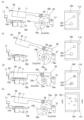
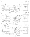
- FIG. 2 is an explanatory diagram sequentially illustrating the steps of crushing tablets using the drug crushing device of FIG. 1, in which the left figure shows the attitude of the crushing unit, and the right figure is a plan view of the drug packaging bag after each step is completed.
- FIG. 2 is a perspective view showing the state in which a drug packaging bag is attached to the drug crushing device of Figure 1 and the tablets in the drug packaging bag are crushed, (a) shows the state in which the hammer member has been lowered, and (b) shows the state in which the bag is being sent out after crushing has been completed.
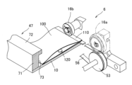
- the drug crushing device 1 of this embodiment is a device that is equipped with a band-like connected drug packaging bag 100 as shown in Figure 12, applies an external force to the tablets 120 (drugs) contained in the drug packaging bag 100 to crush the drugs, and sends the crushed drug packaging bag 100 to the outside.
- the positions in Figures 1 and 12 are used as references, and the side where the medicine packaging bag 100 is introduced is referred to as the "introduction side,” and the side where the medicine packaging bag 100 is discharged is referred to as the "discharge side.”
- the drug crushing device 1 of this embodiment includes a main body device 3 fixed to a base 2 as shown in FIGS.
- the main body device 3 is mainly composed of a crushing section 5 and a feeding means 6 .
- the crushing unit 5 hits the medicine packaging bag 100 to crush the tablets 120 (medicines) therein.
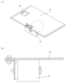
- the crushing unit 5 has a mounting table 10 on which the medicine packaging bag 100 is mounted, and a hammer member (hammer portion) 11.
- a vibrator 12 is attached to the mounting table 10 as a vibration means, and the vibrator 12 causes vibration.
- the feed means 6 has a drive side belt mechanism 15 and pressing side rollers 16a, 16b, and 16c, and holds one side of the drug packaging bag 100 between the two, and feeds out the drug packaging bag 100 by running the drive side belt mechanism 15.
- the drug crushing device 1 of this embodiment also includes crushing confirmation means 8 for detecting whether the tablet 120 has been crushed.
- the crushing confirmation means 8 detects the height of the hammer member (hammer portion) 11 when it strikes the drug to determine the degree of crushing, and is composed of a confirmation sensor 17 and a dog 80 as shown in Figs. 1, 8 to 11.
- the crushing section 5 has the placement table 10 on which the medicine packaging bag 100 is placed, and the hammer member (hammer section) 11 .
- the crushing section 5 has a lateral support member 20 for supporting each member as shown in FIG. 3, and the mounting table 10 and the hammer member 11 are attached to the lateral support member 20.
- the lateral support member 20 has opposed vertical walls 21a, 21b as shown in FIG.
- the mounting table 10 is a substantially rectangular metal plate having considerable rigidity.
- An opening 22 is provided at one end of the mounting table 10.
- a photoelectric sensor (not shown) is provided below the opening 22.
- the photoelectric sensor is a sensor that detects whether or not the medicine packaging bag 100 is present on the mounting table 10.
- a vibrator 12 is attached to the lower part of the mounting table 10 as shown in FIGS.
- the mounting table 10 is fixed on a lateral support member 20 with a certain degree of freedom, and can be vibrated in the vertical direction relative to the mounting table 10 .
- the mallet member 11 is generally plate-shaped, with the tip end region being made particularly thick. That is, the thick region at the tip of the mallet member 11 functions as a striking portion 25 , and the other thin plate-like region functions as a handle portion 26 .
- the striking section 25 is a low rectangular parallelepiped having considerable rigidity and weight.
- the planar shape of the striking section 25 is substantially rectangular and is substantially similar to the shape of the mounting table 10.
- the planar shape of the striking section 25 is slightly smaller than that of the mounting table 10.
- the end of the handle 26 of the mallet member 11 is supported by the lateral support member 20 via a pin 27.
- the handle 26 of the mallet member 11 is supported in a cantilevered manner so as to be rotatable, and the mallet member 11 can be swung up or down.
- a cam follower 28 is provided on the side surface of the mallet member 11 between the pin 27 and the striking portion 25 .
- a dog 80 is provided at the center in the width direction at the tip (free end) of the striking part 25.
- the dog 80 reflects light emitted from the confirmation sensor 17 and is a member to be detected by the photoelectric sensor.
- the dog 80 is made by bending a metal plate into an “L” shape, and has an attachment piece 82 and a detection piece 83 .
- the dog 80 is attached to the tip of the mallet member 11 with an attachment piece 82 fixed to the upper surface of the striking portion 25.
- the detection piece 83 of the dog 80 is located at a position protruding from the free end of the striking portion 25 and hangs down from the upper surface of the striking portion 25.
- the mallet member 11 is cantilevered and rotatable, and is lifted by the cam mechanism 30 and struck against the mounting table 10 from a certain height.
- the cam mechanism 30 is made up of cams 31 a and 31 b , the cam follower 28 of the mallet member 11 , and a power transmission mechanism 32 that rotates the cam 31 .
- the contours of the cams 31a, 31b are each formed by two sets of involute curves connected by two steps 33a, 33b, as shown in Figures 8 to 11. That is, the cams 31a, 31b each have two curved portions 35a, 35b whose distance from the center gradually increases, and two steps 33a, 33b.
- the power transmission mechanism 32 is made up of a motor 37, a reducer 38, and a gear train 40.
- An output shaft (not shown) of the motor 37 is connected to a reducer 38.
- An output shaft of the reducer 38 is connected to a small gear 41 of a gear train 40.
- the small gear 41 is engaged with a large gear 42.
- the large gear 42 is connected to a camshaft 45, and the cams 31a and 31b described above are attached to the camshaft 45.
- the layout of the power transmission mechanism 32 in this embodiment is as shown in Figure 3, and the motor 37 and the reducer 38 are housed in the area surrounded by the vertical walls 21a, 21b of the lateral support member 20, below the camshaft 45.
- the gear train 40 is outside the vertical walls 21 a, 21 b of the lateral support member 20 .
- the cam shaft 45 is rotatably supported by the vertical walls 21a, 21b of the lateral support member 20, and the two cams 31a, 31b are located in an area surrounded by the vertical walls 21a, 21b.
- the rotational force of the motor 37 is reduced in speed by the reducer 38 and the gear train 40 of the power transmission mechanism 32 and transmitted to the camshaft 45, causing the cams 31a and 31b to rotate.
- the height of the cam follower 28 engaged with the cams 31a, 31b changes, causing the mallet member 11 to swing up and down. That is, when the cams 31a, 31b rotate with the cam follower 28 engaged with the curved portions 35a, 35b of the cams 31a, 31b, the mallet member 11 swings upward and the striking portion 25 is lifted.
- the feeding means 6 includes the driving belt mechanism 15 and the pressing rollers 16a, 16b, and 16c.
- the feeding means 6 also includes a guide portion 47.
- the feeding means 6 has a vertical support member 46 for supporting each member as shown in FIG.
- the vertical support member 46 has an introduction side support portion 48 and a discharge side support portion 50 .
- the introduction side support portion 48 is composed of a left vertical wall 51 a and a right vertical wall 51 b.
- the left vertical wall 51 a and the right vertical wall 51 b both extend perpendicularly to the vertical wall 21 b of the lateral support member 20 in a plan view.
- the discharge side support portion 50 is also composed of a left vertical wall 52a and a right vertical wall 52b.
- the left vertical wall 52a and the right vertical wall 52b each extend perpendicularly to the vertical wall 21a of the lateral support member 20 in a plan view.
- the driving belt mechanism 15 includes a driving pulley 53 and a driven pulley 55 around which a feed belt 56 is suspended. A tension pulley 57 is in contact with the feed belt 56.
- the drive pulley 53 receives power from a geared motor 60 and rotates. That is, the power transmission mechanism 61 of the drive belt mechanism 15 is composed of a geared motor 60, a belt transmission section 62, and a transmission shaft 63.
- the belt transmission section 62 is composed of a small pulley 58, a large pulley 65, and a transmission belt 66 suspended between them.
- the output shaft of the geared motor 60 is connected to the small pulley 58 of the belt transmission unit 62.
- the large pulley 65 of the belt transmission unit 62 is connected to a transmission shaft 63.
- the pressing roller 16a is a large diameter roller and is pressed downward by a pressing member 67.
- the pressing rollers 16b and 16c are both small diameter rollers and have an arm portion 68.
- a torsion spring 70 is engaged with the arm portion 68, pressing the roller downward.
- the guide section 47 has a vertical wall 71 and an upper wall 72 as shown in FIG. 5, with a groove-shaped section 73 formed between them.
- the upper portion of the feed belt 56 advances along the upper side of the mounting table 10 from the drive-side pulley 53 side toward the driven-side pulley 55 side, and the lower portion of the feed belt 56 advances along the lower side of the mounting table 10 from the driven-side pulley 55 side toward the drive-side pulley 53 side.
- the pressure side rollers 16a, 16b, and 16c are arranged in series directly above the upper side of the feed belt 56.
- the pressure side roller 16a is located at the most entrance side, followed by the other pressure side rollers 16b and 16c on the discharge side.
- the power transmission mechanism 61 of the drive side belt mechanism 15 is located on the introduction side of the mounting table 10 and is supported by the left vertical wall 51 a and the right vertical wall 51 b of the introduction side support portion 48 .
- the geared motor 60 of the power transmission mechanism 61 is housed in an area surrounded by the left vertical wall 51a and the right vertical wall 51b.
- the belt transmission unit 62 is located outside the left vertical wall 51a.
- the transmission shaft 63 is rotatably supported at both ends by the left vertical wall 51a and the right vertical wall 51b, and the drive pulley 53 is located in the area surrounded by the left vertical wall 51a and the right vertical wall 51b, near the right vertical wall 51b.
- the driven pulley 55 is supported by the discharge side support portion 50 .
- the guide portion 47 is provided on the mounting table 10 on a side opposite to the side on which the drive-side belt mechanism 15 is provided.
- the positional relationship between the table 10 and the feed means 6 will be roughly described as follows: the feed belt 56 is disposed along one side of the table 10, and the groove-like portion 73 of the guide portion 47 extends along the opposing side.
- the confirmation sensor 17 is a reflective photoelectric sensor and is disposed on the guide portion 47.
- the confirmation sensor 17 detects the height of the hammer member 11 after it has struck the medicine packaging bag 100 .
- the confirmation sensor 17 detects the detection piece 83 of the dog 80 .
- the confirmation sensor 17 cannot detect the detection piece 83 of the dog 80 . In this way, the confirmation sensor 17 is in the OFF state when the height of the hammer member 11 after striking the drug packaging bag 100 is high, and is in the ON state when the height of the hammer member 11 after striking the drug packaging bag 100 is low.
- the base 2 is composed of a metal plate 85 that is rectangular in plan view and four legs 86.
- the legs 86 are not all the same height, and the metal plate 85 of the base 2 is inclined.
- the height of the base side of the hammer member 11 is lower than that of the mounting table 10 side.
- the drug crushing device 1 of this embodiment is inclined as a whole, thereby preventing the entire device from moving due to the impact when the mallet member 11 is struck down.
- a guide cover 87 is provided on the introduction side of the drug crushing device 1 of this embodiment, on the geared motor 60 of the power transmission mechanism 61 of the feed means 6.
- the guide cover 87 is arc-shaped, and its upper end side reaches the vicinity of the mounting table 10.
- the side of the loading platform 10, the introduction side, has a guide wall 88 as shown in Figures 1 and 12.
- the end of the guide wall 88 is widened to easily receive the drug packaging strip 107.
- the drug crushing device 1 of this embodiment is a device that is equipped with the drug packaging bag 100 connected in a strip shape, hits the tablets 120 (drugs) contained in the drug packaging bag 100 with the hammer member 11 to crush the drugs, and sends the crushed drug packaging bag 100 to the outside.
- the medicine packaging bag 100 is formed by folding medicine packaging paper 101 in half, inserting a tablet 120 into the bag, and heat-sealing the three sides surrounding the tablet. 7, a roll of medicine packaging paper 101 is fed and folded by a triangular plate 102. Then, tablets are inserted from a hopper 103 into the folded medicine packaging paper 101.
- the sealing device 105 seals the area where the tablets 120 have been inserted by fusing.
- the medicine packaging bags 100 that have passed through the sealing device 105 are connected in a strip shape. There are perforations (not shown) between adjacent medicine packaging bags 100.
- the medicine packaging band 107 in which the medicine packaging bags 100 are connected in a band shape, has a joint edge 110 to which the medicine packaging paper 101 is joined on one side of the band.
- the drug crushing device 1 Before use, the drug crushing device 1 has no drug packaging bag 100 and the mallet member 11 lowered, as shown in FIG. 8( a ). 8B, the mallet member 11 is manually lifted up.
- the cam mechanism 30 employed in this embodiment has only the function of lifting the mallet member 11, so the cam mechanism 30 does not hinder the manual lifting of the mallet member 11.
- One end of the drug packaging strip 107 is placed on the introduction side of the mounting table 10.
- the orientation of the drug packaging strip 107 is such that the joining edge 110 faces the drive belt mechanism 15 and the folded side enters the groove portion 73 of the guide portion 47 as shown in FIG. Then, the drive-side belt mechanism 15 is driven.
- the medicine packaging band 107 is sandwiched between the feed belt 56 and the pressing-side roller 16a, and proceeds to the discharge side as the feed belt 56 travels.
- the first medicine packaging bag 100 is introduced into the mounting table 10, and when a part of the medicine packaging bag 100 reaches the position of the opening 22 of the mounting table 10, a photoelectric sensor (not shown) in the opening 22 detects the medicine packaging bag 100, and the feed belt 56 stops.
- the medicine packaging bag 100 at the leading end of the medicine packaging band 107 is placed on the mounting table 10, as shown in FIG. 8(c).
- the succeeding portion of the medicine packaging strip 107 slides smoothly over the guide cover 87.
- the mallet member 11 swings downward due to gravity, and the striking part 25 falls and strikes the medicine packaging bag 100 on the mounting table 10.
- the tablet 120 breaks as shown in the right diagram of Fig. 9(g).
- the pieces remain in one lump. Therefore, the broken pieces are large, and the mallet member 11 is on the broken pieces after striking the medicine packaging bag 100, so the striking part 25 stops at a high position as shown in Fig. 9(g). Therefore, the confirmation sensor 17 cannot detect the detection piece 83 of the dog 80 attached to the striking part 25.
- the cam follower 28 reaches the boundary between the curved portion 35b and the step portion 33a of the cams 31a, 31b, as shown in FIG. 10(i), and the height of the impact portion 25 reaches its maximum point.
- the cam follower 28 reaches the step 33a of the cams 31a and 31b as shown in Fig. 10(j), and the cam follower 28 suddenly loses support, causing the striking part 25 to fall and strike the medicine packaging bag 100 on the mounting table 10 again.
- the tablet 120 breaks into small pieces as shown in the right figure.
- the striking portion 25 reaches a lower position compared to after the first strike, the dog 80 does not reach the position of the confirmation sensor 17, and the confirmation sensor 17 cannot detect the detection piece 83 of the dog 80.
- the cam follower 28 reaches the boundary between the curved portion 35a and the step portion 33b of the cams 31a, 31b, and the height of the impact portion 25 reaches its maximum point.
- the cam follower 28 reaches the step 33b of the cams 31a and 31b as shown in Fig. 11(m)
- the cam follower 28 suddenly loses support, causing the striking part 25 to fall and strike the medicine packaging bag 100 on the mounting table 10 again.
- the fragments of the tablet 120 become even smaller as shown in the right figure. 11(m)
- the dog 80 reaches the position of the confirmation sensor 17.
- the confirmation sensor 17 detects the detection piece 83 of the dog 80.
- the confirmation sensor 17 detects the detection piece 83 of the dog 80, the impact is stopped and a feeding step is performed to discharge the medicine packaging bag 100. That is, on the condition that the crushing confirmation means 8 confirms that the tablets 120 have been crushed, the medicine packaging bag 100 is fed by the feeding means 6. Specifically, the confirmation sensor 17 detects the detection piece 83 of the dog 80, and when the crushing confirmation means 8 confirms that the tablet 120 has been crushed, the motor 37 starts, the cams 31a, 31b rotate, the impact portion 25 is lifted, and the impact portion 25 moves away from the pharmaceutical packaging bag 100. Next, the feeding means 6 is started, and the feeding belt 56 starts to run.
- the medicine packaging bag 100 on the placement table 10 is held by the feeding belt 56 and the pressing side roller 16a, and therefore advances to the discharge side as the feeding belt 56 runs.
- the feed belt 56 of the drive belt mechanism 15 travels for the distance of one drug packaging bag 100 and then automatically stops.
- the next medicine packaging bag 100 is automatically pulled into the placement table 10 . Then, the above-mentioned process is carried out for the next medicine packaging bag 100 .
- the sensor 17 Since the sensor 17 detects the detection piece 83 of the dog 80 when a medicine packaging bag 100 that does not contain medicines is struck once, the medicine packaging band 107 is conveyed after one strike, and the next medicine packaging bag 100 is struck.
- the number of times to hit the tablet 120 is arbitrary, but it is preferable to hit the tablet 120 a plurality of times. A strong hit is required to crush the tablet 120 into small pieces with a single hit, and there is a concern that the medicine packaging bag 100 may be broken.
- the medicines are inspected before being handed over to the patient. It is desirable to crush the medicines after the inspection is completed, because the tablets 120 have markings or specific shapes, and if they are crushed, the markings and the like become unidentifiable. Specifically, the medicine packaging bag 100 before crushing is photographed by a camera of the inspection device, and the medicine inside is visually confirmed, and then the medicine is crushed by the medicine crushing device 1.
- the crushing section 5 employed in the drug crushing device 1 described above has a striking section 25 and a handle section 26 like a hammer, and the handle section 26 is supported at one end and lifted by a cam, but the present invention is not limited to this configuration.
- a weight-shaped impact part may be lifted straight up by a lifter or the like and then dropped.
- the striking portion may strike the medicine packaging by the elastic force of a leaf spring or a helical spring, without relying on gravity.
- a crank or a screw may be used as the mechanism for lifting the striking part.
- the external force applied to the tablet 120 is not limited to an impact force such as a blow, but may be a static force such as crushing with a roller or press.
- a roller or press often resulted in the drug packaging bag 100 being torn.
- the area of the striking surface of the striking portion 25 is approximately the same as that of the drug packaging bag 100, and the striking portion 25 strikes the drug packaging bag 100 as a whole, but the striking portion 25 may also be made smaller and be configured to strike the tablet 120 specifically.
- the medicine packaging bag 100 is photographed to confirm the position of the tablets, and only the tablets 120 are tapped.
- a plurality of mallet members having different shapes may be selectively used.
- a mallet member having a round tip or a mallet member having a flat tip may be used to crush the tablet 120 depending on the state of breakage of the tablet 120 or the shape of the tablet 120.
- the mallet members having different shapes may be alternately used to strike the tablet, or a mallet member having an appropriate shape may be automatically selected.
- the rollers When a configuration is adopted in which rollers are used to crush the tablets, the rollers may be simply circular, but may also have an uneven surface.
- a roller may be placed on a plate, and the medicine packaging bag 100 may be sandwiched between the plate and the roller to crush the tablets 120 inside.
- the medicine packaging bag 100 may be sandwiched between two rollers to crush the tablets 120 inside.
- the roller may have an elliptical cross section.
- the vibrator 12 vibrates the mounting table 10, which in turn vibrates the drug packaging bag 100, but the mounting table 10 may be vibrated using something other than a vibrator.
- the mounting table 10 may be vibrated by hitting it with a knocker or the like.
- the medicine packaging bag 100 may also be vibrated directly.
- the timing for vibrating the medicine packaging bag 100 is preferably after the crushing operation has been performed in the crushing unit 5, but the tablets may be hit while the medicine packaging bag 100 is being vibrated.
- the feeding means 6 employed in this embodiment holds only one side of the medicine packaging bag 100 and moves the medicine packaging bag 100.
- the joining side 110 of the medicine packaging strip 107 is held to feed the medicine packaging strip 107.
- the joining side 110 of the medicine packaging strip 107 is a portion where no tablets are present and has a constant thickness, which has the advantage that the feeding means is less likely to become clogged.
- the present invention is not limited to this configuration, and the medicine packaging strip 107 may be moved by holding the other side or both sides.
- the mechanism for feeding the drug packaging bag 100 is not limited to this embodiment, and a conveyor, rollers, etc. may also be used.
- the feed rate of the feed means 6 can be set according to the size of the medicine packaging bag 100 to be crushed. If the feed amount of the feed means 6 is fixed and cannot be changed, it is recommended that it be set to match the smallest bag to be used or smaller. When the feed amount of the feed means 6 is smaller than the number of the medicine packaging bags 100 actually used, the struck medicine packaging bags 100 cannot be completely fed in one feed, but the medicine packaging bags 100 are simply struck more, and no major adverse effect occurs.
- the length of the striking portion 25 (actually, a length slightly shorter than the length of the striking portion 25).
- the feeding amount of the feeding means 6 is larger than the drug packaging bag 100 actually used, or if it is larger than the length of the striking portion 25, there is a possibility that tablets 120 will be ejected without being struck, which is undesirable.
- the perforation may be detected by a sensor and the feed means 6 may be started or stopped with reference to the sensor. For example, it is conceivable to feed the drug packaging bag 100 until the perforation is detected.
- a photoelectric sensor is used as the confirmation sensor 17, but the structure of the confirmation sensor is arbitrary.
- it may be a proximity sensor. It may also be a contact type sensor such as a limit switch.
- the mounting position of the confirmation sensor and the mounting position of the dog are arbitrary.
- the degree of cracking of the tablet is detected from the height of the mallet member 11, but the tablet grain shape may also be detected, for example, from an image.
- the drug crushing device 1 desirably has a sensor that detects whether or not the drug contained in the drug packaging bag 100 is a drug that needs to be crushed. If the medicine in the medicine packaging bag 100 that has arrived at the mounting table 10 is a medicine that needs to be crushed, it is struck. If the medicine in the medicine packaging bag 100 that has arrived at the mounting table 10 is not a medicine that needs to be crushed, it is sent out by the sending means 6 without being struck.
- some medicine packaging devices discharge tablets in the order of the time of taking the tablets, and there are cases where a medicine packaging bag 100 containing powdered medicine is discharged following a medicine packaging bag 100 containing tablets 120.
- a medicine packaging bag 100 containing powdered medicine is discharged following a medicine packaging bag 100 containing tablets 120.
- the drug packaging device is capable of packaging drugs that require crushing and drugs that do not require crushing in separate bags.
- the drug packaging device not only packages drugs in the order of their taking time and generates a drug packaging band containing a mixture of drug packaging bags 100 containing drugs that require crushing and drug packaging bags 100 containing drugs that do not require crushing, but also generates a "drug packaging band 107A" in which drug packaging bags 100 containing only drugs that require crushing are connected, and a "drug packaging band 107B" in which drug packaging bags 100 containing only drugs that do not require crushing are connected.
- the drug crushing device 1 does not have the function of not performing crushing when it detects a drug packaging bag 100 containing a drug that does not require crushing, by passing only the "drug packaging band 107A" through the drug crushing device 1, it is possible to prevent drugs that do not require crushing from being crushed.
- the "drug packaging band 107A" may be composed of drug packages 100 for drugs that need to be crushed, which are specified by multiple prescription data, rather than a single prescription data. In this way, the drugs that need to be crushed, which are specified by multiple prescription data, can be crushed by simply passing the "drug packaging band 107A" through the drug crushing device 1 once.
- the above-described embodiment is a drug crushing device for crushing solid drugs contained in a bag
- the drug crushing device has a crushing section which applies an external force to the drug while it is in the bag to crush the drug, and a vibration means, and vibrates the bag with the vibration means at least after the crushing operation has been performed in the crushing section.
- the crushing unit has a platform on which the bag is placed and a hammer, and while the bag is placed on the platform, the hammer strikes the bag to crush the medicine, and it is desirable to vibrate the platform using the vibration means.
- the crushing unit has a platform on which the bag is placed and a hammer, and while the bag is placed on the platform, the hammer strikes the bag to crush the medicine. It is desirable that the crushing action of striking the hammer against the medicine be performed multiple times on one bag to crush the medicine.
- the crushing unit has a platform on which the bag is placed and a hammer, and while the bag is placed on the platform, the hammer strikes the bag to crush the medicine.
- the hammer has a striking part and a handle, and the handle is supported in a cantilevered and rotatable manner. It is preferable that the handle is rotated to lift the striking part, and the striking part is allowed to fall naturally and strike the bag to crush the medicine.
- the embodiment described above is a drug crushing device that crushes solid drugs contained in a bag, and has a crushing unit that applies an external force to the drugs while they are in the bag to crush the drugs, and a crushing confirmation means that detects whether the drugs have been crushed, the crushing unit has a hammer part that crushes the drugs by striking the bag, and the crushing confirmation means detects the height of the hammer when it has struck the drugs.
Landscapes
- Health & Medical Sciences (AREA)
- Life Sciences & Earth Sciences (AREA)
- Animal Behavior & Ethology (AREA)
- General Health & Medical Sciences (AREA)
- Public Health (AREA)
- Veterinary Medicine (AREA)
- Engineering & Computer Science (AREA)
- Food Science & Technology (AREA)
- Chemical & Material Sciences (AREA)
- Medicinal Chemistry (AREA)
- Pharmacology & Pharmacy (AREA)
- Basic Packing Technique (AREA)
Abstract
Description
しかしながら、錠剤をのみ込むことが困難な患者もある。
そのような患者に対して錠剤が処方された場合、薬剤師等が乳鉢等で錠剤をすり潰して散薬状にし、患者に服用させる場合がある。
本発明は、従来技術の上記した問題に注目し、錠剤等の固形状の薬剤を潰す装置を開発することを課題とするものである。
本態様は、この事実に注目したものであり、薬剤に打ち付けられた状態における槌の位置を検知することによって、間接的に破砕後の薬剤の大きさを知り、薬剤が破砕されたか否かを確認することができる。
前記した位置は、何らかの基準位置からの距離であることが望ましい。
本態様の薬剤破砕装置の送り手段は、接合辺を保持して前記帯状に繋がった袋を移動させる。ここで接合辺は、薬剤が存在しない辺であるから、平面的に置いたときに凹凸が少ない。
本態様の薬剤破砕装置では、凹凸が少ない接合辺を保持するので、袋をしっかりと保持することができ、袋を円滑に送ることができる。また接合辺には薬剤が存在しないので、送り動作が薬剤によって邪魔されないという効果も期待できる。
本態様の薬剤破砕装置は、振動手段を有し、少なくとも破砕部で破砕動作が行われた後に前記振動手段で袋を振動させる。そのため固まった状態の破片が振動によって分離される。その後例えば再度薬剤を叩くことにより、薬剤の破片がより細かくなる。
本実施形態の薬剤破砕装置1は、図12の様に、帯状に繋がった薬剤包装袋100を装着し、薬剤包装袋100に入った状態の錠剤120(薬剤)に外力を加えて薬剤を破砕し、破砕し終えた薬剤包装袋100を外部に送り出す装置である。
以下の説明においては、図1、図12の姿勢を基準とし、薬剤包装袋100の導入側を「導入側」と称し、薬剤包装袋100が排出される側を「排出側」と称する。
本体装置3は、大きく分けて破砕部5と、送り手段6によって構成されている。
破砕部5は、薬剤包装袋100を叩いて中の錠剤120(薬剤)を潰すものである。破砕部5は、図1(a)、図2、図3、図12(b)等の様に、薬剤包装袋100を載置する載置台10と槌部材(槌部)11を有している。載置台10には図6、図8乃至図11の様に振動手段としてバイブレータ12が取り付けられていて当該バイブレータ12によって振動する。
また本実施形態の薬剤破砕装置1は、錠剤120が破砕されたか否かを検知する破砕確認手段8を備えている。破砕確認手段8は、薬剤に打ち付けられた状態における槌部材(槌部)11の高さを検知することによって、破砕の程度を知るものであり、図1、図8乃至図11の様に、確認センサー17とドグ80によって構成されている。
破砕部5は、前記した様に、薬剤包装袋100を載置する載置台10と槌部材(槌部)11を有している。
破砕部5は、図3の様に各部材を支持する横支持部材20を有し、当該横支持部材20に載置台10と槌部材11が取り付けらせれている。
横支持部材20は、図3の様に対向する縦壁21a、21bを有している。
載置台10の一端側には開口22が設けられている。開口22の下部には図示しない光電センサーが設けられている。光電センサーは、載置台10に薬剤包装袋100が有るか否かを検知するセンサーである。
載置台10の下部には図6、図8乃至図11の様に、バイブレータ12が取り付けられている。
載置台10は、横支持部材20の上にある程度の自由度をもって固定されており、載置台10に対して上下方向に振動可能である。
即ち槌部材11は、先端の肉厚領域が打撃部25として機能し、他の厚さが薄い板状の領域は柄部26として機能する。
打撃部25は、高さの低い直方体であり、相当の剛性と重量を有している。打撃部25の平面形状は略四角形であり、載置台10と略相似形である。打撃部25の平面形状は、載置台10に比べてやや小さい。
槌部材11の側面であって、ピン27と打撃部25の間に、カムフォロア28が設けられている。
ドグ80は、金属板が「L」状に折り曲げられたものであり、取り付け片82と検知片83を有している。
ドグ80は、図1の様に、打撃部25の上面に取り付け片82が固定された状態で槌部材11の先端部に取り付けられている。ドグ80の検知片83は、打撃部25の自由端から突出した位置にあり、打撃部25の上面から垂下している。
カム機構30は、図3の様に、カム31a、31bと、前記した槌部材11のカムフォロア28と、カム31を回転させる動力伝動機構32によって構成されている。
カム31a、31bの輪郭は、図8乃至図11の様に、いずれも二組のインボリュート曲線が二か所の段部33a、33bで繋がれたものである。即ちカム31a、31bはいずれも中心からの距離が次第に広がってゆく二つの曲線部35a、35bと、二つの段部33a、33bを有している。
モータ37の出力軸(図示せず)は、減速機38に接続されている。減速機38の出力軸は、歯車列40の小歯車41に接続されている。小歯車41は、大歯車42と係合している。そして大歯車42がカム軸45に接続されており、当該カム軸45に前記したカム31a、31bが取り付けられている。
歯車列40は、横支持部材20の縦壁21a、21bの外側にある。
カム軸45は、横支持部材20の縦壁21a、21bに回転可能に支持されており、二つのカム31a、31bは、縦壁21a、21bに囲まれた領域にある。
その結果、カム31a、31bと係合するカムフォロア28の高さが変化し、槌部材11が上下に揺動する。
即ち、カムフォロア28がカム31a、31bの曲線部35a、35bと係合している状態でカム31a、31bが回転すると、槌部材11が上方に揺動し、打撃部25が持ち上げられる。
打撃部25が最高点に達し、さらにカム31a、31bが回転すると、カムフォロア28がカム31a、31bの段部33a、33bに至り、カムフォロア28は一気に支持を失う。その結果、重力によって槌部材11が下方向に揺動し、打撃部25が落下する。
送り手段6は、前記した様に、駆動側ベルト機構15と、押さえ側ローラ16a、16b、16cを有している。また送り手段6に付属するものとしてガイド部47がある。
送り手段6は、図4の様に各部材を支持する縦支持部材46を有し、当該縦支持部材46に各部材が取り付けらせれている。
縦支持部材46は、図4の様に導入側支持部48と、排出側支持部50を有している。
導入側支持部48は、左側縦壁51aと、右側縦壁51bによって構成されている。左側縦壁51aと、右側縦壁51bは、いずれも前記した横支持部材20の縦壁21bに平面視で垂直方向にのびるものである。
排出側支持部50についても、左側縦壁52aと、右側縦壁52bによって構成されている。左側縦壁52aと、右側縦壁52bは、いずれも前記した横支持部材20の縦壁21aに平面視で垂直方向にのびるものである。
駆動側プーリ53は、ギャードモータ60から動力伝動を受けて回転する。
即ち駆動側ベルト機構15の動力伝動機構61は、ギャードモータ60と、ベルト伝導部62と、伝導軸63によって構成されている。ベルト伝導部62は、小プーリ58と、大プーリ65と、両者に懸架された伝動ベルト66によって構成されている。
ギャードモータ60の出力軸は、ベルト伝導部62の小プーリ58に接続されている。ベルト伝導部62の大プーリ65は、伝導軸63に接続されている。
即ち駆動側ベルト機構15の駆動側プーリ53と従動側プーリ55は、載置台10から前後に離れた位置に配置されており、送りベルト56は、載置台10の辺部を取り巻く位置に配置されている。送りベルト56の上部に位置する部分は、載置台10の上部側を駆動側プーリ53側から従動側プーリ55側に向かって進み、送りベルト56の下部に位置する部分は、載置台10の下部側を従動側プーリ55側から駆動側プーリ53側に向かって進む。
動力伝動機構61のギャードモータ60は、左側縦壁51aと右側縦壁51bで囲まれた領域に収納されている。ベルト伝導部62は、左側縦壁51aの外側にある。伝導軸63は、左側縦壁51aと右側縦壁51bで両端が回転可能に支持されており、駆動側プーリ53は、左側縦壁51aと右側縦壁51bで囲まれた挟まれた領域であって、右側縦壁51bの近傍にある。
従動側プーリ55は、排出側支持部50に支持されている。
載置台10と送り手段6の位置関係を概説すると、載置台10の一方の辺に沿って送りベルト56が配置され、対向する辺に沿ってガイド部47の溝状部73がのびている。
確認センサー17は、反射型の光電センサーである。確認センサー17は、ガイド部47の上に設置されている。
確認センサー17は、薬剤包装袋100を打ち付けた後の槌部材11の高さを検知するものである。
槌部材11に叩かれて錠剤が細かく砕け、打撃部25が載置台10の近傍の高さまで下がった状態で停止すると、確認センサー17がドグ80の検知片83を検知する。
一方、破砕が不十分であり、打撃部25が載置台10から大きく浮き上がった状態で停止した場合には、確認センサー17がドグ80の検知片83を検知することができない。
この様に、確認センサー17は、薬剤包装袋100を打ち付けた後の槌部材11の高さが高い場合は、オフ状態となり、薬剤包装袋100を打ち付けた後の槌部材11の高さが低い場合は、オン状態となる。
基台2は、平面視が四角形の金属板85と、4個の脚部86によって構成されている。脚部86の高さは同じではなく、基台2の金属板85は、傾斜している。
本実施形態では、図2の様に、載置台10側に比べて槌部材11の根本側の高さが低い。
本実施形態の薬剤破砕装置1は、全体的に傾斜姿勢にすることにより、槌部材11が打ち下ろされた時の衝撃によって全体が移動することを防いでいる。
図1と図4(a)を見比べて理解できるように、本実施形態の薬剤破砕装置1の導入側であって、送り手段6の動力伝動機構61のギャードモータ60にはガイドカバー87が設けられている。ガイドカバー87は円弧状であり、その上端側は、載置台10の近傍に至っている。
本実施形態の薬剤破砕装置1は、前記した様に、帯状に繋がった薬剤包装袋100を装着し、薬剤包装袋100に入った状態で錠剤120(薬剤)を槌部材11で叩いて薬剤を破砕し、破砕し終えた薬剤包装袋100を外部に送り出す装置である。次に薬剤包装袋100について説明する。
薬剤包装袋100は、薬包紙101を二つ折りにして錠剤120を投入し、錠剤を囲む三方を熱融着して袋を形成したものである。
具体的には、図7の様に、ロール状の薬包紙101が送られて、三角板102で当該薬包紙101が折り曲げられる。そしてその中に、折り曲げられた間にホッパ103から錠剤が投入される。
そしてその後、シール装置105で錠剤120が投入された部分の周囲を融着して密閉する。シール装置105を通過した薬剤包装袋100は、帯状に繋っている。隣接する薬剤包装袋100の間には、図示しないミシン目がある。
薬剤包装袋100が帯状に繋がった薬剤包装帯107は、帯状の一辺に薬包紙101が接合された接合辺110がある。
次に、薬剤破砕装置1の動作について説明する。
使用前の薬剤破砕装置1は、図8(a)の様に、薬剤包装袋100は無く、槌部材11が降下している。
この状態から図8(b)の様に、手動で槌部材11を跳ね上げる。本実施形態で採用するカム機構30は、単に槌部材11を持ち上げる機能のみを持つものであるから、槌部材11を手動で持ち上げることについてはカム機構30が障害になることはない。
そして駆動側ベルト機構15を駆動する。その結果、薬剤包装帯107は、送りベルト56と押さえ側ローラ16aの間に挟み込まれ、送りベルト56の走行に従って排出側に進む。最初の薬剤包装袋100が、載置台10に導入され、薬剤包装袋100の一部が載置台10の開口22の位置に達すると、開口22内の図示しない光電センサーが薬剤包装袋100を検知し、送りベルト56が停止する。この動作によって、図8(c)の様に、薬剤包装帯107の先端部の薬剤包装袋100を載置台10に載せる。
最初の薬剤包装袋100が載置台10に導入される際、薬剤包装帯107の後続部分は、ガイドカバー87の上を滑って円滑に進む。
そして図示しない自動スイッチを押す。その結果、図示しない制御装置によって以下の工程が、自動的に実行される。
モータ37が起動して、図9(e)の様に、カム31a、31bが回転し、カムフォロア28がカム31a、31bの曲線部35aに沿って上昇し、打撃部25が徐序に持ち上げられる。
カム31a、31bの回転が進み、図9(f)の様に、カムフォロア28がカム31a、31bの曲線部35aと段部33bの境界に至り、打撃部25の高さが最高点に達する。
さらにカム31a、31bの回転が進み、図9(g)の様に、カムフォロア28がカム31a、31bの段部33bに至り、カムフォロア28は一気に支持を失う。その結果、重力によって槌部材11が下方向に揺動し、打撃部25が落下し、載置台10上の薬剤包装袋100を叩く。その結果、図9(g)の右図の様に、錠剤120が割れる。しかしながら、破片は一塊の状態となっている。
そのため破片は大きい状態であり、薬剤包装袋100を打ち付けた後の槌部材11は、破片上にあるため、図9(g)の様に、打撃部25は高い位置で停止している。そのため確認センサー17が打撃部25に取り付けられたドグ80の検知片83を検知することができない。
第一打撃と同様にモータ37が起動して、図9(h)の様に、カム31a、31bが回転し、カムフォロア28がカム31a、31bの曲線部35bに沿って上昇し、打撃部25が徐序に持ち上げられる。
これと並行してバイブレータ12が起動し、載置台10が振動する。その結果、錠剤120が振動し、図9(h)の右図の様に、破片が散らばる。
なお本実施形態の薬剤破砕装置1は、全体的に傾斜姿勢となっており、載置台10も傾斜している。そのため、バイブレータ12の振動によって錠剤120の破片が散らばりやすい。
さらにカム31a、31bの回転が進み、図10(j)の様に、カムフォロア28がカム31a、31bの段部33aに至り、カムフォロア28は一気に支持を失って打撃部25が落下し、載置台10上の薬剤包装袋100を再度叩く。その結果、右図の様に、錠剤120の破片が細かくなる。
打撃部25は第一打撃の後に比べると低い位置まで至っているが、ドグ80は確認センサー17の位置までは至らず、確認センサー17はドグ80の検知片83を検知することができない。
第一打撃と同様にモータ37が起動して、図10(k)の様に、カム31a、31bが回転し、カムフォロア28がカム31a、31bの曲線部35aに沿って上昇し、打撃部25が徐序に持ち上げられる。
これと並行して図10(k)の様に、バイブレータ12が起動し、載置台10が振動する。その結果、錠剤120が振動し、破片がさらに散らばる。
さらにカム31a、31bの回転が進み、図11(m)の様に、カムフォロア28がカム31a、31bの段部33bに至り、カムフォロア28は一気に支持を失って打撃部25が落下し、載置台10上の薬剤包装袋100を再度叩く。その結果、右図の様に、錠剤120の破片がさらに細かくなる。
打撃部25は第二打撃の後に比べて低い位置まで至り、図11(m)の様に、ドグ80が確認センサー17の位置に到達する。その結果、確認センサー17はドグ80の検知片83を検知する。
確認センサー17はドグ80の検知片83を検知すると、打撃が中断されて薬剤包装袋100を排出する送り工程が実施される。即ち、破砕確認手段8で錠剤120が破砕されたことが確認されたことを条件として、送り手段6によって薬剤包装袋100が送られる。
具体的には、確認センサー17はドグ80の検知片83を検知し、破砕確認手段8で錠剤120の破砕が確認されると、モータ37が起動して、カム31a、31bが回転し、打撃部25が持ち上げられて、打撃部25が薬剤包装袋100から離れる。
続いて送り手段6が起動し、送りベルト56が走行する。その結果、載置台10上の薬剤包装袋100は、送りベルト56と押さえ側ローラ16aで保持されているので、送りベルト56の走行に従って排出側に進む。
駆動側ベルト機構15の送りベルト56は、薬剤包装袋100一個分だけ走行して自動停止する。
前記した様に、薬剤包装袋100は、複数繋がっているので、次の薬剤包装袋100が自動的に載置台10に引き入れられる。
そして次の薬剤包装袋100に対して上記した工程が行われる。
また薬品が入っていない薬剤包装袋100(処方データや患者情報が印字された空の薬剤包装袋100)が存在する薬剤包装帯107であっても、各薬剤包装袋100を順次叩くことができる。薬品が入っていない薬剤包装袋100は1回叩けばセンサー17がドグ80の検知片83を検知するので、1回叩くと薬剤包装帯107が搬送され、次の薬剤包装袋100を叩くことになる。
前記した様に、錠剤120を叩く回数は任意であるが、叩く回数は複数回であることが望ましい。一回の打撃で錠剤120を細かく砕いてしまうには強い打撃が必要であり、薬剤包装袋100が破れてしまう懸念がある。
薬剤は、患者に手渡される前に鑑査が行われる。
薬剤の粉砕は、鑑査が終了した後に実施されることが望ましい。この理由は、錠剤120には刻印があったり特定の形状があるが、破砕してしまうと、刻印等が判別できなくなってしまうためである。
具体的には、破砕前の薬剤包装袋100を鑑査装置のカメラで撮影したり、目視によって内部の薬剤を確認し、鑑査を行う。そしてその後に、薬剤破砕装置1で破砕する。
例えば、錘状の打撃部をリフター等によって真上に持ち上げて落下させるものであってもよい。
また重力に頼らず、板バネやつるまきばねの弾発力によって打撃部を薬剤包装に打ち付けるものであってもよい。
打撃部を持ち上げる機構として、クランクやネジを利用してもよい。
例えば、薬剤包装袋100を撮影して錠剤の位置を確認し、錠剤120だけを叩く。
また形状の異なる複数の槌部材を選択的に使用することができるものであってもよい。例えば錠剤120の破損状態や錠剤120の形状に応じて、先端が円形の槌部材や先端が平らな槌部材を使用して破砕する。形状の異なる槌部材を交互に使用して打撃したり、適切な形状の槌部材を自動的に選択することができるものであってもよい。
板の上にローラを設置した、板とローラの間に薬剤包装袋100を挟み込んで中の錠剤120を潰してもよい。また二つのローラの間に薬剤包装袋100を挟み込んで中の錠剤120を潰してもよい。
この際のローラは、断面形状を楕円形にしてもよい。
またローラで潰す構成を採用する場合、複数回にわたって破砕できるようにローラを並べることが望ましい。
また薬剤包装袋100を直接振動させてもよい。
しかしながら本発明はこの構成に限定されるものでなく、他の辺や双方の辺を保持して薬剤包装帯107を移動させるものであってもよい。
送り手段6の送り量が固定されて変更することができない場合は、使用する最小の袋にあわせるか、より小さめにしておくことが推奨される。
送り手段6の送り量が実際に使用される薬剤包装袋100よりも小さい場合は、一回の送りで打撃済の薬剤包装袋100を送りきることができないが、薬剤包装袋100がより多く叩かれるだけであり、大きな弊害は起きない。
逆に、送り手段6の送り量が実際に使用さる薬剤包装袋100よりも大きい場合や、打撃部25の長さ分よりも大きい場合は、叩かれずに排出されてしまう錠剤120が発生する場合があり、好ましくない。
隣接する薬剤包装袋100の間には、図示しないミシン目があるので、当該ミシン目をセンサーで検知し、それを参照して送り手段6の起動・停止を行ってもよい。例えばミシン目を検出するまで薬剤包装袋100を送ることが考えられる。
上記した実施形態では、槌部材11の高さから、錠剤の割れ具合を検知したが、例えば画像によって錠剤の粒形を検知してもよい。
載置台10に到着した薬剤包装袋100の薬剤が、破砕が必要な薬剤であるならば、打撃を行う。載置台10に到着した薬剤包装袋100の薬剤が、破砕が必要な薬剤でないならば、打撃することなく、送り手段6で送り出す。
しかしながら、潰すことが想定される錠剤については、散薬とは別の薬剤包装袋100錠剤が入れられることが望ましい。
また薬剤破砕装置1を使用し易い様に、潰すことが想定される錠剤120が収容された薬剤包装袋100が薬剤分包装置から連続的に排出されることが望ましい。即ち薬剤分包装置は、服用時期の順に排出されるものがあり、錠剤120が収容された薬剤包装袋100に続いて散薬が収容された薬剤包装袋100が排出されるような場合がある。この様な場合には、服用時期よりも錠剤120の潰しやすさを優先して、潰すことが想定される錠剤120が収容された薬剤包装袋100が、薬剤分包装置から連続的に排出されることが望ましい。
前記袋に入った状態で薬剤に外力を加えて当該薬剤を破砕する破砕部と、振動手段を有し、少なくとも破砕部で破砕動作が行われた後に前記振動手段で袋を振動させる薬剤破砕装置である。
前記袋に入った状態で薬剤に外力を加えて当該薬剤を破砕する破砕部と、前記薬剤が破砕されたか否かを検知する破砕確認手段を有し、前記破砕部は槌部を有し、前記槌部を袋に打ち付けて薬剤を破砕するものであり、前記破砕確認手段は、薬剤に打ち付けられた状態における槌の高さを検知する薬剤破砕装置である。
5 破砕部
6 送り手段
8 破砕確認手段
10 載置台
11 槌部材
12 バイブレータ(振動手段)
15 駆動側ベルト機構
16a、16b、16c 押さえ側ローラ
17 確認センサー
28 カムフォロア
31a、31b カム
56 送りベルト
80 ドグ
100 薬剤包装袋
107 薬剤包装帯
110 接合辺
120 錠剤
Claims (5)
- 袋に入った固形状の薬剤を破砕する薬剤破砕装置であって、
前記袋に入った状態で薬剤に外力を加えて当該薬剤を破砕する破砕部と、前記薬剤が破砕されたか否かを検知する破砕確認手段とを有し、
前記破砕確認手段で薬剤が破砕されたことが確認されたことを条件として、前記袋を破砕部から相対的に移動させることを特徴とする薬剤破砕装置。 - 前記袋を送る送り手段を有し、
前記破砕確認手段で薬剤が破砕されたことが確認されたことを条件として、前記送り手段によって前記袋を送ることを特徴とする請求項1に記載の薬剤破砕装置。 - 前記破砕部は槌部を有し、前記槌部を袋に打ち付けて薬剤を破砕するものであり、
前記破砕確認手段は、薬剤に打ち付けられた状態における槌の位置を検知するものであることを特徴とする請求項1に記載の薬剤破砕装置。 - 前記袋は薬包紙によって構成されたものであって、複数の袋が帯状に繋がっており、帯状の一辺に前記薬包紙が接合された接合辺があり、
前記送り手段は、前記接合辺を保持して前記帯状に繋がった袋を移動させるものであることを特徴とする請求項1に記載の薬剤破砕装置。 - 振動手段を有し、少なくとも破砕部で破砕動作が行われた後に前記振動手段で袋を振動させることを特徴とする請求項1乃至4のいずれかに記載の薬剤破砕装置。
Priority Applications (3)
| Application Number | Priority Date | Filing Date | Title |
|---|---|---|---|
| KR1020257009174A KR20250052430A (ko) | 2023-01-20 | 2023-12-29 | 약제 파쇄 장치 |
| JP2024571693A JPWO2024154587A1 (ja) | 2023-01-20 | 2023-12-29 | |
| US19/241,447 US20250312242A1 (en) | 2023-01-20 | 2025-06-18 | Drug crushing device |
Applications Claiming Priority (2)
| Application Number | Priority Date | Filing Date | Title |
|---|---|---|---|
| JP2023-007189 | 2023-01-20 | ||
| JP2023007189 | 2023-01-20 |
Related Child Applications (1)
| Application Number | Title | Priority Date | Filing Date |
|---|---|---|---|
| US19/241,447 Continuation US20250312242A1 (en) | 2023-01-20 | 2025-06-18 | Drug crushing device |
Publications (1)
| Publication Number | Publication Date |
|---|---|
| WO2024154587A1 true WO2024154587A1 (ja) | 2024-07-25 |
Family
ID=91955905
Family Applications (1)
| Application Number | Title | Priority Date | Filing Date |
|---|---|---|---|
| PCT/JP2023/047364 Ceased WO2024154587A1 (ja) | 2023-01-20 | 2023-12-29 | 薬剤破砕装置 |
Country Status (4)
| Country | Link |
|---|---|
| US (1) | US20250312242A1 (ja) |
| JP (1) | JPWO2024154587A1 (ja) |
| KR (1) | KR20250052430A (ja) |
| WO (1) | WO2024154587A1 (ja) |
Citations (3)
| Publication number | Priority date | Publication date | Assignee | Title |
|---|---|---|---|---|
| JP2002020802A (ja) * | 2000-04-21 | 2002-01-23 | Sumitomo Special Metals Co Ltd | 粉体プレス装置および当該装置を用いた希土類磁石の製造方法 |
| JP2017012791A (ja) * | 2012-12-20 | 2017-01-19 | ユウ キム,テ | 薬調剤装置 |
| JP2022188176A (ja) * | 2021-04-27 | 2022-12-20 | 株式会社湯山製作所 | 散薬秤量装置 |
-
2023
- 2023-12-29 JP JP2024571693A patent/JPWO2024154587A1/ja active Pending
- 2023-12-29 KR KR1020257009174A patent/KR20250052430A/ko active Pending
- 2023-12-29 WO PCT/JP2023/047364 patent/WO2024154587A1/ja not_active Ceased
-
2025
- 2025-06-18 US US19/241,447 patent/US20250312242A1/en active Pending
Patent Citations (3)
| Publication number | Priority date | Publication date | Assignee | Title |
|---|---|---|---|---|
| JP2002020802A (ja) * | 2000-04-21 | 2002-01-23 | Sumitomo Special Metals Co Ltd | 粉体プレス装置および当該装置を用いた希土類磁石の製造方法 |
| JP2017012791A (ja) * | 2012-12-20 | 2017-01-19 | ユウ キム,テ | 薬調剤装置 |
| JP2022188176A (ja) * | 2021-04-27 | 2022-12-20 | 株式会社湯山製作所 | 散薬秤量装置 |
Also Published As
| Publication number | Publication date |
|---|---|
| US20250312242A1 (en) | 2025-10-09 |
| JPWO2024154587A1 (ja) | 2024-07-25 |
| KR20250052430A (ko) | 2025-04-18 |
Similar Documents
| Publication | Publication Date | Title |
|---|---|---|
| US8959878B2 (en) | Tablet inspecting device | |
| CN102458344B (zh) | 旋转式药片分配器 | |
| US5101612A (en) | Capsule filling apparatus | |
| EP2489595A2 (en) | Packaging machine | |
| WO2024154587A1 (ja) | 薬剤破砕装置 | |
| JP4274417B2 (ja) | 薬剤包装装置 | |
| KR102159551B1 (ko) | 알약 분쇄기 | |
| US4274531A (en) | Apparatus for orienting oblong articles | |
| KR20210003010A (ko) | 알약 분쇄기 | |
| CN100427362C (zh) | 药剂包装装置 | |
| JP2004269008A (ja) | 錠剤計数監査装置 | |
| JP2004238066A (ja) | 錠剤計数監査装置 | |
| KR102952312B1 (ko) | 약품 분쇄기 | |
| JPH09323704A (ja) | 薬剤包装機 | |
| KR102345620B1 (ko) | 약제 포장지 배출 장치 | |
| KR102521338B1 (ko) | 알약 분쇄기 | |
| KR100599511B1 (ko) | 약제다발 커팅장치 | |
| CN206841815U (zh) | 胶囊调头加料机构 | |
| JP7206450B1 (ja) | 整形装置および搬送コンベア | |
| KR100650287B1 (ko) | 가루약 자동 포장기의 낙하량 조절장치 | |
| CN100473583C (zh) | 药剂包装装置 | |
| KR101511260B1 (ko) | 약제 포장장치의 컨베이어 모듈 | |
| JP3488808B2 (ja) | 硬貨包装機 | |
| JP2004236997A (ja) | 錠剤計数監査装置 | |
| CN211810434U (zh) | 一种药剂包装装置的药包输出机构 |
Legal Events
| Date | Code | Title | Description |
|---|---|---|---|
| 121 | Ep: the epo has been informed by wipo that ep was designated in this application |
Ref document number: 23917796 Country of ref document: EP Kind code of ref document: A1 |
|
| WWE | Wipo information: entry into national phase |
Ref document number: 2024571693 Country of ref document: JP |
|
| ENP | Entry into the national phase |
Ref document number: 20257009174 Country of ref document: KR Kind code of ref document: A |
|
| WWE | Wipo information: entry into national phase |
Ref document number: 1020257009174 Country of ref document: KR |
|
| WWP | Wipo information: published in national office |
Ref document number: 1020257009174 Country of ref document: KR |
|
| NENP | Non-entry into the national phase |
Ref country code: DE |
|
| 122 | Ep: pct application non-entry in european phase |
Ref document number: 23917796 Country of ref document: EP Kind code of ref document: A1 |