WO2024154346A1 - コネクタ、嵌合間口、および取付部材 - Google Patents
コネクタ、嵌合間口、および取付部材 Download PDFInfo
- Publication number
- WO2024154346A1 WO2024154346A1 PCT/JP2023/001746 JP2023001746W WO2024154346A1 WO 2024154346 A1 WO2024154346 A1 WO 2024154346A1 JP 2023001746 W JP2023001746 W JP 2023001746W WO 2024154346 A1 WO2024154346 A1 WO 2024154346A1
- Authority
- WO
- WIPO (PCT)
- Prior art keywords
- opening
- housing
- panel
- crush ribs
- connector
- Prior art date
- Legal status (The legal status is an assumption and is not a legal conclusion. Google has not performed a legal analysis and makes no representation as to the accuracy of the status listed.)
- Ceased
Links
Images


Classifications
-
- H—ELECTRICITY
- H01—ELECTRIC ELEMENTS
- H01R—ELECTRICALLY-CONDUCTIVE CONNECTIONS; STRUCTURAL ASSOCIATIONS OF A PLURALITY OF MUTUALLY-INSULATED ELECTRICAL CONNECTING ELEMENTS; COUPLING DEVICES; CURRENT COLLECTORS
- H01R13/00—Details of coupling devices of the kinds covered by groups H01R12/70 or H01R24/00 - H01R33/00
- H01R13/73—Means for mounting coupling parts to apparatus or structures, e.g. to a wall
Definitions
- This disclosure relates to connectors, mating openings, and mounting members.
- Electric vehicles are becoming more popular worldwide.
- the storage batteries that power the vehicles need to be charged as needed, which necessitates equipment.
- Patent Document 1 One proposal for solving these problems is disclosed in Patent Document 1.
- the connector disclosed in Patent Document 1 includes a housing that is divided into a vehicle body mounting portion and a connector main body portion.
- the vehicle body mounting portion has a cylindrical outer tube portion, and the connector main body portion is fitted into this outer tube portion.
- the connector main body portion is standardized for all vehicles, and the vehicle body mounting portion is shaped to match the vehicle.
- the connector includes a mating opening for charging and an attachment portion for attaching the mating opening to a vehicle, the attachment portion including a panel portion having a first surface and a second surface with an opening formed between the first surface and the second surface, and a flange portion having a fixture for attaching the panel portion to a vehicle and formed around the panel portion,
- the mating opening may include a cylindrical housing containing a group of terminals for charging therein, and the housing has an abutment portion that abuts against the peripheral portion of the second surface side of the opening such that when the housing is mated with the opening from the second surface side, the tip of the housing is positioned in a predetermined relationship with the first surface.
- FIG. 1 is a perspective view of a connector according to a first embodiment of the present disclosure before assembly.
- FIG. 2 is a perspective view of the connector according to the first embodiment of the present disclosure after assembly.
- FIG. 3 is a perspective view of the connector after assembly, as seen from the rear.
- FIG. 4 is a perspective view of a member for mounting the connector to a vehicle.
- FIG. 5 is a rear perspective view of the mounting member 60 of the connector according to the first embodiment.
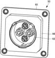
- FIG. 6 is a front view of the mounting member.
- FIG. 7 is a cross-sectional view taken along the line 7-7 in FIG.
- FIG. 8 is an enlarged view of a portion of FIG.
- FIG. 9 is an enlarged view of a portion of FIG. FIG.
- FIG. 10 is a front view of the fitting opening of the connector according to the first embodiment.
- FIG. 11 is a cross-sectional view taken along the line 11-11 of FIG.
- FIG. 12 is a partially enlarged view of FIG.
- FIG. 13 is a partially enlarged view of FIG.
- FIG. 14 is a front view of the connector 50 after assembly.
- 15 is a cross-sectional view taken along the line 15-15 in FIG.
- FIG. 16 is a partially enlarged view of FIG.
- FIG. 17 is an enlarged view of a portion of FIG.
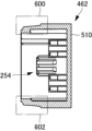
- FIG. 18 is a perspective view of a connector according to the second embodiment of the present disclosure before assembly.
- FIG. 19 is a perspective view of the connector according to the second embodiment of the present disclosure after assembly.
- FIG. 20 is a perspective view of the connector after assembly as seen from the rear.
- FIG. 21 is an enlarged view of a portion of the mounting member shown in FIG.
- FIG. 22 is a rear perspective view of the member for mounting the connector to the vehicle.
- FIG. 23 is an enlarged view of a portion of FIG.
- FIG. 24 is a perspective view of a mating frontage according to a second embodiment of the present disclosure.
- FIG. 25 is a perspective view of the fitting opening as seen from an angle different from that of FIG.
- FIG. 26 is a front view of the mounting member.
- 27 is a cross-sectional view taken along the line 27-27 in FIG.
- FIG. 28 is an enlarged view of a portion of FIG.
- FIG. 29 is an enlarged view of a partial area of FIG. 30 is a cross-sectional view taken along the line 30-30 of FIG. 26.
- FIG. 31 is an enlarged view of a portion of FIG.
- FIG. 32 is an enlarged view of a portion of FIG.
- FIG. 33 is a front view of the fitting opening.
- 34 is a cross-sectional view taken along the line 34-34 of FIG. 33.
- FIG. FIG. 35 is an enlarged view of a portion of FIG.
- FIG. 36 is a partially enlarged view of FIG. 37 is a cross-sectional view taken along the line 37-37 in FIG.
- FIG. 38 is a partially enlarged view of FIG.
- FIG. 39 is a partially enlarged view of FIG.
- FIG. 40 is a front view of the connector when the fitting opening is assembled to the mounting member.
- 41 is a cross-sectional view taken along the line 41-41 of FIG.
- FIG. 42 is a partially enlarged view of FIG.
- FIG. 45 is
- the purpose of this disclosure is to provide a connector, a mating opening, and a mounting member that allow easy assembly of parts.
- a connector includes a mating opening for charging and an attachment portion for attaching the mating opening to a vehicle, the attachment portion including a panel portion having a first surface and a second surface with an opening formed between the first surface and the second surface, and a flange portion having a fixture for attaching the panel portion to a vehicle and formed around the panel portion, the mating opening may include a cylindrical housing containing a group of terminals for charging therein, the housing having an abutment portion that abuts against the periphery of the second surface side of the opening such that when the housing is mated with the opening from the second surface side, the tip of the housing is positioned in a predetermined relationship with the first surface.
- This configuration makes it easy to assemble the parts.
- the peripheral edge of the opening on the second surface side of the panel portion is chamfered. This configuration makes it easy to fit the housing into the opening of the panel portion.
- a predetermined area on the outer circumferential surface of the housing which is adjacent to the abutment portion from the tip side of the housing, is formed to have a larger taper than the taper from the predetermined area to the tip of the housing.
- a step is formed on the outer peripheral surface of the housing at a position a predetermined distance away from the abutment portion toward the tip. This configuration makes it easy to assemble the parts and to position the fitting opening.
- the shape of the inner circumference of the opening in the panel portion has a taper such that the inner diameter of the opening increases as it approaches the specified area from the first surface. This configuration makes it easier to assemble parts.
- the connector may further include three or more housing-side crush ribs formed on the outer peripheral surface of the housing in a predetermined area that contacts the abutment portion from the tip side of the housing. This configuration makes it easy to assemble the parts and to position the mating opening.
- the connector may include four or more of the housing-side crush ribs. This configuration makes it easy to assemble the parts and to position the mating opening.
- the housing has a central axis that is oriented in the same direction as the insertion direction of the housing into the opening, and the three or more housing-side crush ribs are formed in positions that are rotationally symmetrical with respect to the central axis. This configuration makes it easy to assemble the parts and to position the fitting opening.
- the three or more housing-side crush ribs are formed in linearly symmetrical positions. This configuration makes it easier to assemble the parts and to position the fitting opening.
- the connector may further include three or more panel-side crush ribs formed on the inner peripheral surface of the opening of the panel portion in an area closer to the first surface than to the second surface. This configuration makes it easy to assemble the parts and to position the mating opening.
- the connector may include four or more of the housing-side crush ribs. This configuration makes it easy to assemble the parts and to position the mating opening.
- the housing has a central axis that is oriented in the same direction as the direction in which the housing is inserted into the opening, and the three or more panel-side crush ribs are formed in positions that are rotationally symmetrical about the central axis of the housing when the housing is fitted into the opening. This configuration makes it easy to assemble the parts and to position the fitting opening.
- the three or more panel-side crush ribs are formed in linearly symmetrical positions. This configuration makes it easy to assemble the parts and to position the fitting opening.
- the connector may further include three or more housing-side crush ribs formed on the outer peripheral surface of the housing in a predetermined area that contacts the abutment portion from the tip side of the housing, and three or more panel-side crush ribs formed on the inner peripheral surface of the opening of the panel portion in an area closer to the first surface than the second surface, and at least one of the three or more housing-side crush ribs and at least one of the three or more panel-side crush ribs are formed in positions that face each other and do not interfere with each other when the fitting opening is fitted into the opening.
- This configuration makes it easy to assemble the parts and also easy to position the fitting opening.
- a mating opening is a mating opening that is a part of a connector that is attached to a vehicle, the connector including the mating opening and an attachment portion for attaching the mating opening to the vehicle, the attachment portion including a panel portion having a first surface and a second surface and an opening formed between the first surface and the second surface, and a flange portion having a fixture for attaching the panel portion to the vehicle and formed around the panel portion,
- the mating opening includes a cylindrical housing that contains a group of terminals for charging therein, the housing has an abutment portion that abuts against the peripheral portion of the second surface side of the opening so that when the housing is mated with the opening from the second surface side, the tip of the housing is positioned in a predetermined relationship with the first surface, and on the outer circumferential surface of the housing, a predetermined area from the tip side of the housing adjacent to the abutment portion is formed so as to have a larger taper than the taper from the predetermined area
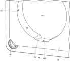
- FIG. 1 shows a perspective view of a connector 50 according to a first embodiment of this disclosure before the attachment member 60 and the fitting opening 62 are assembled.
- Fig. 2 shows a perspective view of the connector 50 after the attachment member 60 and the fitting opening 62 are assembled.
- Fig. 3 is a view of the connector 50 shown in Fig. 2 as seen from the back side.
- the connector 50 includes the attachment member 60 and the fitting opening 62, all of which are formed of insulating resin.
- the mounting member 60 includes a panel portion 66 in the shape of a rectangular parallelepiped having a substantially square front surface 70.
- the panel portion 66 has an opening 64 into which the fitting opening 62 is fitted.
- the outer periphery of the opening 64 is substantially circular and is defined by an inner circumferential surface 72 of the panel portion 66.
- the mounting member 60 further includes a flange 68 formed on the periphery of the panel portion 66 opposite the front surface 70.
- the flange 68 has a mounting fixture for mounting the mounting member 60 to the vehicle body.
- the fitting opening 62 is substantially cylindrical. As shown in Figures 2 and 3, the front portion of the fitting opening 62 fits into the opening 64 from the back side.
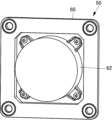
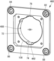
- FIG. 4 is a perspective view of the mounting member 60 as viewed from the front
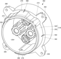
- FIG. 5 is a perspective view of the mounting member 60 as viewed from the rear
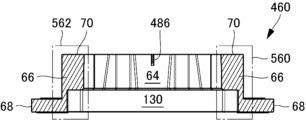
- FIG. 6 is a front view of the mounting member 60.
- FIG. 7 is a cross-sectional view taken along the line 7-7 in FIG. 6.
- FIG. 8 is an enlarged view of area 180 in FIG. 7,
- FIG. 9 is an enlarged view of area 182 in FIG. 7.
- the detailed shape of the mounting member 60 will be described with reference to FIGS. 4, 5, 6, 7, 8, and 9.
- the mounting member 60 includes a rectangular parallelepiped panel portion 66 having a substantially square front surface 70 as described above, and a flange 68 provided on the back side of the panel portion 66.
- a substantially circular opening 64 is formed in the panel portion 66.
- the outer periphery of the opening 64 is substantially circular, but its inner circumferential surface 72 is formed with recesses 74, 76, 78, and 80 into which protrusions formed on the outer periphery of the front portion of the fitting opening 62 are inserted.
- the flange 68 is also square with rounded corners.
- the four corners of the flange 68 are provided with mounting holes 82, 84, 86, and 88, which are fasteners into which screws are inserted to attach the mounting member 60 to the vehicle body.
- the front surface 90 of the flange 68 is parallel to the front surface 70.
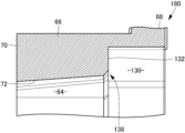
- a substantially square opening 130 wider than the opening 64 is formed on the back surface 148 of the panel portion 66.
- the periphery of the opening 130 is defined by side surfaces 134.
- the deepest part of the opening 130 forms the bottom surface 132.
- the opening 64 opens on the back surface side at the bottom surface 132.
- a chamfered portion 138 is formed at the corner of the boundary portion of the opening 64. The presence of the chamfered portion 138 allows the fitting opening 62 to be smoothly inserted into the opening 64, making assembly easier and improving work efficiency.
- the four corners of the opening 130 are chamfered, and the bottom surface 132 in the vicinity thereof is formed with screw holes 140, 142, 144 and 146 for fixing the fitting opening 62.
- the outside of the fitting portion 250 forms an abutment surface 362. 8 and 9 when the fitting opening 62 is inserted into the opening 64 of the mounting member 60, the abutment surface 362 abuts against the bottom surface 132 shown in Figures 8 and 9, thereby preventing the fitting opening 62 from moving further into the opening 64. Due to the function of the abutment surface 362, when the fitting opening 62 is fitted into the opening 64 of the mounting member 60, the tip portion of the fitting opening 62 becomes approximately flush with the front surface 70 of the mounting member 60.
- the four portions of the periphery of the rear housing 252 that come into contact with the abutment surfaces 362 are provided with overhangs 260, 262, 264, and 266. Openings are formed in each of these overhangs.
- the fitting opening 62 is fixed to the mounting member 60 by passing a screw through these openings and screwing it into the screw holes 140 shown in FIG. 5, for example.
- protrusions 270, 272, 274, and 276 are formed at predetermined portions. These are determined by standards, and their positions are determined so that the charging plug is properly connected to the mounting member 60 during charging. Spaces are formed inside these protrusions.
- protrusion 276 at the bottom has the function of collecting water that has entered the space 254 during rainy weather and discharging it to the outside.
- recesses 78, 76, 80, and 74 are formed at positions corresponding to protrusions 270, 272, 274, and 276 on the inner periphery of the opening 64, respectively.
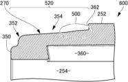
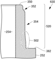
- FIG. 12 is a cross-sectional view of the protrusion 270 shown in FIG. 10.
- the mating portion 250 is formed continuously at the end of the rear housing 252. Inside the protrusion 270, a space 360 is formed that is continuous with the space 254.
- the upper part of the mating portion 250 is raised higher than the other parts due to the protrusion 270, but includes the tip surface 350, the tip side surface 352, and the side surface 354.
- the side surface 354 is formed so as to expand with a certain taper from the tip side of the mating portion 250, that is, so that the outer diameter of the mating portion 250 becomes larger.
- the taper of the side surface 354 becomes slightly sharper in the region 358 that contacts the abutment surface 362 of the rear housing 252, thereby forming a step.
- This step is much smaller than the outer periphery of the mating portion 250. This step is formed not only at the protrusion 270 but all around the mating portion 250.
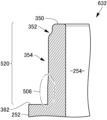
- FIG. 13 is a cross-sectional view of the protrusion 276 in FIG. 10.
- a space 390 that is continuous with the space 254 is formed inside the protrusion 276 in this portion as well.
- the space 390 has a drainage port (not shown) that leads to the outside of the housing 240.
- the fitting portion 250 has a tip surface 350, a tip side surface 352, and a side surface 354 that spreads outward with a certain taper.
- a portion that has a steeper taper than the other portions of the side surface 354 is formed, as in FIG. 12.
- a step that is much smaller is formed in the region 358 compared to the outer periphery of the fitting portion 250.
- FIG. 14 is a front view of connector 50 obtained by assembling fitting opening 62 to mounting member 60
- Fig. 15 is a cross-sectional view taken along the arrows 15-15 in Fig. 14.
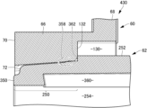
- Fig. 16 is an enlarged view of region 430 in Fig. 15, and
- Fig. 17 is an enlarged view of region 432 in Fig. 15.
- the fitting opening 62 is assembled to the mounting member 60 so that the front surface 70 of the mounting member 60 and the tip surface 350 of the fitting opening 62 are approximately flush with each other.
- the inner peripheral surface 72 of the panel portion 66 and the step portion of the area 358 of the outer periphery of the fitting portion 250 of the fitting opening 62 are fitted together, and the fitting opening 62 is positioned radially in the opening 64.
- the step portion of the area 358 is formed over the entire outer periphery of the fitting portion 250, and the fitting portion 250 of the fitting opening 62 is correctly positioned in the center of the opening 64.
- a very small gap is formed between the inner peripheral surface 72 of the mounting member 60 and the side surface 354 of the fitting portion 250 on the tip side of the area 358. For example, if a light is provided behind the fitting opening 62 during charging to indicate that charging is in progress, light will leak evenly through this gap to the front of the connector, which is functional and also has an aesthetic effect.
- the step is formed around the entire circumference of the fitting portion 250, but this disclosure is not limited to such an embodiment.
- the step may be formed only on a portion of the circumference of the fitting portion 250. In that case, in order to correctly align the fitting opening 62 and the mounting member 60, it is desirable to form the step at a position that is symmetrical about the center line of the opening 64 in the vertical or horizontal directions, or to provide the step at a position that is rotationally symmetrical about the central axis of the opening 64 in the front-to-rear direction.
- a step portion such as region 358 is formed on the outside of fitting portion 250.
- this disclosure is not limited to such an embodiment.
- a step that reduces the inner diameter of opening 64 may be provided in the region adjacent to chamfered portion 138 inside opening 64.
- a step is provided over the entire outer periphery of the fitting portion 250.
- this disclosure is not limited to an embodiment in which a step is provided on the outer periphery of the fitting portion 250 or on the inner periphery of the opening 64 of the mounting member 60 in this manner.
- a protrusion of an appropriate size such as a crush rib, may be formed at an appropriate position.
- the second embodiment is such an example.
- the connector according to the second embodiment includes a mounting member 460 having an opening 64, and a mating opening 462 that fits into the opening 64 of the mounting member 460.
- the mounting member 460 and the mating opening 462 are substantially the same as the mounting member 60 and the mating opening 62 according to the first embodiment, but as described below, a feature is that crush ribs are provided on part of the outer periphery of the mating opening 462 and part of the inner periphery of the opening 64, instead of the step provided on the outer periphery of the mating opening 62 in the first embodiment.
- FIG. 21 is an enlarged view of a portion of the mounting member 460 shown in Fig. 18.
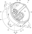
- Fig. 22 shows the back surface of the mounting member 460
- Fig. 23 is an enlarged view of a portion of Fig. 22.
- Fig. 26 is a plan view of the mounting member 460.
- Fig. 27 is a cross-sectional view taken along the arrows 27-27 in Fig. 26.
- Fig. 28 is an enlarged view of a region 530 in Fig. 27, and
- Fig. 29 is an enlarged view of a region 532 in Fig. 27.
- Fig. 30 is a cross-sectional view taken along the arrows 30-30 in Fig. 26.
- Fig. 31 is an enlarged view of a region 560 in Fig. 30, and
- Fig. 32 is an enlarged view of a region 562 in Fig. 30.
- the difference between the mounting member 460 and the mounting member 60 according to the first embodiment is that the mounting member 460 has crush ribs 482 (FIGS. 21, 22, 23, 26, and 29), crush ribs 484 (FIGS. 21, 22, 26, and 32), crush ribs 486 (FIGS. 26 and 28), and crush ribs 488 (FIGS. 26 and 31) on the front surface 70 at four locations on the top, bottom, left, and right of the inner circumferential surface 72.
- the length of these crush ribs is less than half the width of the inner circumferential surface 72, and their height is selected to be much smaller than the inner diameter of the opening 64.
- the crush ribs 486 are formed in the recesses 78 of the inner circumferential surface 72, and the crush ribs 482 are formed in the recesses 74 of the inner circumferential surface 72.
- the crush ribs 484 and 488 are each formed in a portion of the inner circumferential surface 72 other than the recessed portion.
- the mounting member 460 is the same as the mounting member 60 according to the first embodiment.
- Figures 24 and 25 are perspective views of the fitting opening 462 as viewed from different angles.
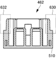
- Figure 33 is a front view of the fitting opening 462.
- Figure 34 is a cross-sectional view taken along the line 34-34 in Figure 33.
- Figure 35 is an enlarged view of a region 600 in Figure 34
- Figure 36 is an enlarged view of a region 602 in Figure 36.
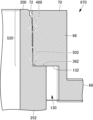
- Figure 37 is a cross-sectional view taken along the line 37-37 in Figure 33.
- Figure 38 is an enlarged view of a region 630 in Figure 37
- Figure 39 is an enlarged view of a region 632 in Figure 37.
- the mating opening 462 includes a housing 510.
- the housing 510 includes a rear housing 252 that is the same as that of the mating opening 62 according to the first embodiment, and a mating portion 520 that is provided on the tip side of the rear housing 252 and is substantially the same as the mating portion 250 according to the first embodiment.
- the mating portion 520 does not have the step provided in the outer peripheral region 358 (FIGS. 12 and 13). Instead, as shown in FIG. 33, FIG. 35, FIG. 36, FIG. 8 and FIG. 39, the mating portion 520 has crush rib 500 (FIGS. 33 and 35), crush rib 502 (FIGS. 33 and 38), crush rib 504 (FIGS. 33 and 36) and crush rib 506 (FIGS. 33 and 39). These crush ribs are provided in positions facing the four crush ribs 486, crush rib 488, crush rib 482 and crush rib 484 provided on the inner peripheral surface 72 of the mounting member 460 when the mating opening 462 is mated with the mounting member 460.
- the crush ribs 500, 502, 504, and 506 are all the same size, and the length in the direction parallel to the central axis of the housing 510 is smaller than half the width of the housing 510, and the height is selected to be much smaller than the outer diameter of the fitting portion 520.
- the fitting opening 462 is the same as the fitting opening 62 of the first embodiment.
- the sizes of the four crush ribs 486, 488, 482, and 484 provided on the inner peripheral surface 72 of the mounting member 460 are the same as the crush ribs 500, 502, 504, and 506. Therefore, when the fitting opening 462 is fitted to the opening 64 of the mounting member 460, the crush ribs of the mounting member 460 and the crush ribs of the fitting opening 462 do not interfere with each other.
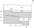
- FIG. 40 shows a state in which fitting opening 462 has been assembled to mounting member 460 in connector 450 according to the second embodiment.
- Fig. 41 is a cross-sectional view taken along the arrows 41-41 shown in Fig. 40.
- Fig. 42 is an enlarged view of region 640 in Fig. 41, and
- Fig. 43 is an enlarged view of region 642 in Fig. 41.
- Fig. 44 is a cross-sectional view taken along the arrows 43-43 shown in Fig. 40.
- Fig. 45 is an enlarged view of region 670 in Fig. 44
- Fig. 46 is an enlarged view of region 672 in Fig. 44.
- a chamfered portion 138 is formed at the boundary between the bottom surface 132 of the mounting member 460 and the opening 64, as in the first embodiment. Therefore, the fitting opening 462 can be easily inserted into the opening 64 of the mounting member 460, improving work efficiency.
- the outer periphery of the fitting portion 520 and the inner periphery 72 of the mounting member 460 come into contact with each other.
- the inner periphery 72 of the opening 64 of the mounting member 460 and the outer periphery of the fitting portion 520 of the fitting opening 462 are in close contact with each other in the area where these crush ribs are formed.
- a small gap is formed between the inner periphery 72 of the opening 64 and the outer periphery of the fitting portion 520.
- crush ribs such as crush ribs 486 and crush ribs 500 do not come into contact with the mating surface until just before insertion is completed, ensuring workability when assembling the fitting opening 462 to the mounting member 460.
- crush ribs such as crush ribs 486 and crush ribs 500 come into strong contact with the mating surface, allowing the mounting member 460 to firmly hold the fitting opening 462.
- These crush ribs also allow the fitting opening 462 to be correctly positioned in the opening 64 of the mounting member 460. As a result, the mounting member 460 and the fitting opening 462 can be reliably assembled while ensuring workability.
- the crush ribs of the mounting member 460 and the crush ribs of the fitting opening 462 are positioned so that they face each other when the fitting opening 462 is fitted into the mounting member 460.
- this disclosure is not limited to such an embodiment.
- the crush ribs can also be positioned so that they do not face each other when fitted. In that case, there is no need to limit the size of the crush ribs. However, from the perspective of ensuring workability, it is better to avoid making the crush ribs large.
- the crush ribs of the mounting member 460 and the crush ribs of the mating opening 462 are both located at positions that are vertical, horizontal, and lateral when viewed from the front of the connector 450 when the connector 450 is attached to a vehicle.
- these crush ribs are located at positions that are linearly symmetrical to each other with respect to a vertical axis that passes through the center of the front of the connector 450.
- These crush ribs are also located at positions that are linearly symmetrical to each other with respect to a horizontal axis that passes through the front of the connector 450.
- these crush ribs are located at positions that are four-fold rotationally symmetrical with respect to the center point of the front of the connector 450.
- the light leaks forward from the gap formed between the inner circumferential surface 72 of the opening 64 and the outer periphery of the mating portion 520, other than the area where the crush ribs are present.
- This provides an aesthetic effect in that the tip of the mating opening 462 appears to be floating above its surroundings.
- the crush ribs are arranged as described above, the light leaking out when viewed from the front is symmetrical and spaced equally apart. This provides the effect that the tip of the mating opening 462, which is highlighted by the light, appears to shine.
- the same aesthetic effect can be obtained, for example, even if the crush ribs are arranged only vertically symmetrically and not horizontally symmetrically, or even if they are arranged only horizontally symmetrically and not vertically symmetrically.
- the number of crush ribs formed on both the mounting member 460 and the fitting opening 462 is four.
- the number of crush ribs on both sides may be different.
- the number of crush ribs does not have to be four, and may be three or five or more.
- the protrusion of an appropriate size provided at an appropriate position may be a protrusion other than a crush rib.
- it may be a rib other than a crush rib.
Landscapes
- Connector Housings Or Holding Contact Members (AREA)
Priority Applications (3)
| Application Number | Priority Date | Filing Date | Title |
|---|---|---|---|
| CN202380090199.9A CN120476523A (zh) | 2023-01-20 | 2023-01-20 | 连接器、嵌合口及安装构件 |
| JP2024571584A JPWO2024154346A1 (https=) | 2023-01-20 | 2023-01-20 | |
| PCT/JP2023/001746 WO2024154346A1 (ja) | 2023-01-20 | 2023-01-20 | コネクタ、嵌合間口、および取付部材 |
Applications Claiming Priority (1)
| Application Number | Priority Date | Filing Date | Title |
|---|---|---|---|
| PCT/JP2023/001746 WO2024154346A1 (ja) | 2023-01-20 | 2023-01-20 | コネクタ、嵌合間口、および取付部材 |
Publications (1)
| Publication Number | Publication Date |
|---|---|
| WO2024154346A1 true WO2024154346A1 (ja) | 2024-07-25 |
Family
ID=91955620
Family Applications (1)
| Application Number | Title | Priority Date | Filing Date |
|---|---|---|---|
| PCT/JP2023/001746 Ceased WO2024154346A1 (ja) | 2023-01-20 | 2023-01-20 | コネクタ、嵌合間口、および取付部材 |
Country Status (3)
| Country | Link |
|---|---|
| JP (1) | JPWO2024154346A1 (https=) |
| CN (1) | CN120476523A (https=) |
| WO (1) | WO2024154346A1 (https=) |
Citations (6)
| Publication number | Priority date | Publication date | Assignee | Title |
|---|---|---|---|---|
| US20090017705A1 (en) * | 2004-09-27 | 2009-01-15 | Adc Telecommunications, Inc. | High density mount for a co-axial connector |
| WO2015034047A1 (ja) * | 2013-09-06 | 2015-03-12 | 矢崎総業株式会社 | コネクタ |
| US10454197B1 (en) * | 2018-09-26 | 2019-10-22 | Te Connectivity Corporation | Electrical connector with plastic latch integrated into contact cavity |
| JP2020077573A (ja) * | 2018-11-09 | 2020-05-21 | 矢崎総業株式会社 | コネクタ |
| US20220102904A1 (en) * | 2019-01-11 | 2022-03-31 | Phoenix Contact E-Mobility Gmbh | Plug connector part having a connector part to be connected to a housing part |
| JP2023019754A (ja) * | 2021-07-29 | 2023-02-09 | 矢崎総業株式会社 | コネクタ |
-
2023
- 2023-01-20 WO PCT/JP2023/001746 patent/WO2024154346A1/ja not_active Ceased
- 2023-01-20 JP JP2024571584A patent/JPWO2024154346A1/ja active Pending
- 2023-01-20 CN CN202380090199.9A patent/CN120476523A/zh active Pending
Patent Citations (6)
| Publication number | Priority date | Publication date | Assignee | Title |
|---|---|---|---|---|
| US20090017705A1 (en) * | 2004-09-27 | 2009-01-15 | Adc Telecommunications, Inc. | High density mount for a co-axial connector |
| WO2015034047A1 (ja) * | 2013-09-06 | 2015-03-12 | 矢崎総業株式会社 | コネクタ |
| US10454197B1 (en) * | 2018-09-26 | 2019-10-22 | Te Connectivity Corporation | Electrical connector with plastic latch integrated into contact cavity |
| JP2020077573A (ja) * | 2018-11-09 | 2020-05-21 | 矢崎総業株式会社 | コネクタ |
| US20220102904A1 (en) * | 2019-01-11 | 2022-03-31 | Phoenix Contact E-Mobility Gmbh | Plug connector part having a connector part to be connected to a housing part |
| JP2023019754A (ja) * | 2021-07-29 | 2023-02-09 | 矢崎総業株式会社 | コネクタ |
Also Published As
| Publication number | Publication date |
|---|---|
| JPWO2024154346A1 (https=) | 2024-07-25 |
| CN120476523A (zh) | 2025-08-12 |
Similar Documents
| Publication | Publication Date | Title |
|---|---|---|
| US8262413B2 (en) | Shield connector | |
| US10476209B2 (en) | Shield connector | |
| US10179517B2 (en) | Module system for a charging apparatus, charging apparatus and vehicle including a charging apparatus constructed from the module system | |
| US9233615B2 (en) | Vehicle-side connector having a housing with wire draw-out openings in different directions | |
| US7811116B2 (en) | Connector, a connector assembly and a connecting method | |
| US9199589B2 (en) | Vehicle-side charging connector with connector main body usable with plural different vehicles | |
| US9085242B2 (en) | Power plug | |
| KR20220156260A (ko) | 자동차 충전 커넥터 | |
| US20200259276A1 (en) | Connector | |
| US10666002B2 (en) | Wiring harness connecting structure for housed circuit assembly | |
| JP2021034226A (ja) | コネクタ | |
| JP7389896B2 (ja) | 電気プラグコネクタ | |
| CN105981234A (zh) | 连接器 | |
| US8678731B2 (en) | Nut and a housing | |
| WO2024154346A1 (ja) | コネクタ、嵌合間口、および取付部材 | |
| JP2021136133A (ja) | コネクタ | |
| KR20130002432U (ko) | 커넥터 | |
| CN106711718B (zh) | 用于车载压缩机的高低压连接插座和车载压缩机 | |
| CN212114099U (zh) | 车用高压连接器和车辆 | |
| KR20130038442A (ko) | 차량용 고전압 커넥터 | |
| US20060035536A1 (en) | Electrical connector | |
| CN115249934A (zh) | 转接组件 | |
| KR101462664B1 (ko) | 안전커넥터 | |
| JP2012190632A (ja) | ダミー栓及び防水コネクタ | |
| CN224217766U (zh) | 一种插针和卡爪组合的连接器结构 |
Legal Events
| Date | Code | Title | Description |
|---|---|---|---|
| 121 | Ep: the epo has been informed by wipo that ep was designated in this application |
Ref document number: 23917559 Country of ref document: EP Kind code of ref document: A1 |
|
| ENP | Entry into the national phase |
Ref document number: 2024571584 Country of ref document: JP Kind code of ref document: A |
|
| WWE | Wipo information: entry into national phase |
Ref document number: 2024571584 Country of ref document: JP Ref document number: 202380090199.9 Country of ref document: CN |
|
| WWP | Wipo information: published in national office |
Ref document number: 202380090199.9 Country of ref document: CN |
|
| NENP | Non-entry into the national phase |
Ref country code: DE |
|
| 122 | Ep: pct application non-entry in european phase |
Ref document number: 23917559 Country of ref document: EP Kind code of ref document: A1 |