WO2024154294A1 - 通信装置 - Google Patents
通信装置 Download PDFInfo
- Publication number
- WO2024154294A1 WO2024154294A1 PCT/JP2023/001512 JP2023001512W WO2024154294A1 WO 2024154294 A1 WO2024154294 A1 WO 2024154294A1 JP 2023001512 W JP2023001512 W JP 2023001512W WO 2024154294 A1 WO2024154294 A1 WO 2024154294A1
- Authority
- WO
- WIPO (PCT)
- Prior art keywords
- sequence
- shift
- nth
- communication device
- basic
- Prior art date
- Legal status (The legal status is an assumption and is not a legal conclusion. Google has not performed a legal analysis and makes no representation as to the accuracy of the status listed.)
- Ceased
Links
Images







Classifications
-
- H—ELECTRICITY
- H04—ELECTRIC COMMUNICATION TECHNIQUE
- H04L—TRANSMISSION OF DIGITAL INFORMATION, e.g. TELEGRAPHIC COMMUNICATION
- H04L1/00—Arrangements for detecting or preventing errors in the information received
- H04L1/02—Arrangements for detecting or preventing errors in the information received by diversity reception
- H04L1/04—Arrangements for detecting or preventing errors in the information received by diversity reception using frequency diversity
-
- H—ELECTRICITY
- H04—ELECTRIC COMMUNICATION TECHNIQUE
- H04W—WIRELESS COMMUNICATION NETWORKS
- H04W28/00—Network traffic management; Network resource management
- H04W28/16—Central resource management; Negotiation of resources or communication parameters, e.g. negotiating bandwidth or QoS [Quality of Service]
- H04W28/18—Negotiating wireless communication parameters
-
- H—ELECTRICITY
- H04—ELECTRIC COMMUNICATION TECHNIQUE
- H04L—TRANSMISSION OF DIGITAL INFORMATION, e.g. TELEGRAPHIC COMMUNICATION
- H04L27/00—Modulated-carrier systems
- H04L27/26—Systems using multi-frequency codes
- H04L27/2601—Multicarrier modulation systems
- H04L27/2602—Signal structure
- H04L27/2605—Symbol extensions, e.g. Zero Tail, Unique Word [UW]
- H04L27/2607—Cyclic extensions
-
- H—ELECTRICITY
- H04—ELECTRIC COMMUNICATION TECHNIQUE
- H04B—TRANSMISSION
- H04B1/00—Details of transmission systems, not covered by a single one of groups H04B3/00 - H04B13/00; Details of transmission systems not characterised by the medium used for transmission
- H04B1/69—Spread spectrum techniques
- H04B1/713—Spread spectrum techniques using frequency hopping
-
- H—ELECTRICITY
- H04—ELECTRIC COMMUNICATION TECHNIQUE
- H04J—MULTIPLEX COMMUNICATION
- H04J13/00—Code division multiplex systems
- H04J13/0074—Code shifting or hopping
-
- H—ELECTRICITY
- H04—ELECTRIC COMMUNICATION TECHNIQUE
- H04J—MULTIPLEX COMMUNICATION
- H04J13/00—Code division multiplex systems
- H04J13/0077—Multicode, e.g. multiple codes assigned to one user
-
- H—ELECTRICITY
- H04—ELECTRIC COMMUNICATION TECHNIQUE
- H04J—MULTIPLEX COMMUNICATION
- H04J13/00—Code division multiplex systems
- H04J13/10—Code generation
- H04J13/12—Generation of orthogonal codes
-
- H—ELECTRICITY
- H04—ELECTRIC COMMUNICATION TECHNIQUE
- H04J—MULTIPLEX COMMUNICATION
- H04J13/00—Code division multiplex systems
- H04J13/16—Code allocation
- H04J13/18—Allocation of orthogonal codes
-
- H—ELECTRICITY
- H04—ELECTRIC COMMUNICATION TECHNIQUE
- H04J—MULTIPLEX COMMUNICATION
- H04J13/00—Code division multiplex systems
- H04J13/16—Code allocation
- H04J13/22—Allocation of codes with a zero correlation zone
-
- H—ELECTRICITY
- H04—ELECTRIC COMMUNICATION TECHNIQUE
- H04L—TRANSMISSION OF DIGITAL INFORMATION, e.g. TELEGRAPHIC COMMUNICATION
- H04L23/00—Apparatus or local circuits for systems other than those covered by groups H04L15/00 - H04L21/00
- H04L23/02—Apparatus or local circuits for systems other than those covered by groups H04L15/00 - H04L21/00 adapted for orthogonal signalling
-
- H—ELECTRICITY
- H04—ELECTRIC COMMUNICATION TECHNIQUE
- H04L—TRANSMISSION OF DIGITAL INFORMATION, e.g. TELEGRAPHIC COMMUNICATION
- H04L27/00—Modulated-carrier systems
- H04L27/26—Systems using multi-frequency codes
-
- H—ELECTRICITY
- H04—ELECTRIC COMMUNICATION TECHNIQUE
- H04L—TRANSMISSION OF DIGITAL INFORMATION, e.g. TELEGRAPHIC COMMUNICATION
- H04L27/00—Modulated-carrier systems
- H04L27/26—Systems using multi-frequency codes
- H04L27/2601—Multicarrier modulation systems
- H04L27/2602—Signal structure
-
- H—ELECTRICITY
- H04—ELECTRIC COMMUNICATION TECHNIQUE
- H04L—TRANSMISSION OF DIGITAL INFORMATION, e.g. TELEGRAPHIC COMMUNICATION
- H04L27/00—Modulated-carrier systems
- H04L27/26—Systems using multi-frequency codes
- H04L27/2601—Multicarrier modulation systems
- H04L27/2602—Signal structure
- H04L27/261—Details of reference signals
- H04L27/2613—Structure of the reference signals
-
- H—ELECTRICITY
- H04—ELECTRIC COMMUNICATION TECHNIQUE
- H04J—MULTIPLEX COMMUNICATION
- H04J13/00—Code division multiplex systems
- H04J13/0007—Code type
- H04J13/004—Orthogonal
-
- H—ELECTRICITY
- H04—ELECTRIC COMMUNICATION TECHNIQUE
- H04J—MULTIPLEX COMMUNICATION
- H04J13/00—Code division multiplex systems
- H04J13/0007—Code type
- H04J13/0055—ZCZ [zero correlation zone]
Definitions
- This disclosure relates to communications technology.
- Non-Patent Document 1 discloses a communication technology called LoRa (registered trademark) that is used in IoT devices and the like.
- Non-Patent Document 1 when the number of IoT devices communicating with an AP increases, the number of packets that the AP can receive correctly is limited due to the effects of interference, etc. For example, if one AP communicates with 500 IoT devices and each IoT device transmits 1,500 packets per hour, the number of packets that the AP can receive correctly is approximately 200 packets per IoT device.
- a communication device includes a storage means for storing information indicating a first basic set including a first basic sequence to an Nth basic sequence (N is an integer equal to or greater than 2), which are a sequence of L complex numbers (L is an integer equal to or greater than 2); a shift means for determining a shift amount based on data to be transmitted to the first communication device, and generating an Nth shift sequence from the first shift sequence by cyclically shifting the nth basic sequence (n is an integer from 1 to N) by the shift amount; a storage means for holding timing information indicating a transmission timing of a sequence; and a transmission means for transmitting the first shift sequence to the Nth shift sequence according to the timing information, wherein the first base sequence to the Nth base sequence satisfy a first condition that the sum of the correlation values of autocorrelation at a shift amount of 0 across the first base sequence to the Nth base sequence is different from 0, and the sum of the correlation values of autocorrelation at a shift amount different from 0 across the
- FIG. 1 is a configuration diagram of a wireless communication system used to explain an embodiment.
- FIG. 2 is a diagram showing the configuration of a transmitting side of a wireless device.
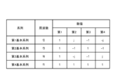
- FIG. 1 shows an example of a basic set.
- FIG. 13 is a diagram showing an example of a shift set. 11A to 11C are diagrams showing examples of transmission of each shift sequence.
- FIG. 2 is a diagram showing the configuration of the receiving side of an access point.
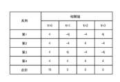
- FIG. 11 is a diagram showing an example of correlation values of periodic correlation.
- FIG. 2 is a diagram showing the configuration of the transmitting side of an access point.
- FIG. 13 is a diagram showing another example of a basic set.
- FIG. 13 is a diagram showing an example of an addition set.
- FIG. 2 is a diagram showing the configuration of a receiving side of a wireless device.
- FIG. 11 is a diagram showing another example of correlation values of periodic correlation.
- FIG. 13 is a diagram showing still another example of correlation values of periodic correlation.
- FIG. 13 is a diagram showing another example of a basic set.
- FIG. 13 is a diagram showing still another example of correlation values of periodic correlation.
- FIG. 11 is a diagram showing an example of mapping information.
- FIG. 1 is a configuration diagram of a wireless communication system used to explain the embodiment.
- An access point (AP) 2 is a communication device capable of wirelessly communicating with wireless devices (WD) 1-1 to 1-3.
- WD1-1 to 1-3 are communication devices capable of wirelessly communicating with AP2.
- WD1-1 to 1-3 are IoT devices.
- WD1-1 to 1-3 are also collectively referred to as WD1.
- AP2 communicates with three WD1, but this is an example, and the number of WD1 with which AP2 communicates may be one or more.
- the direction from WD1 to AP2 is referred to as the uplink direction
- the direction from AP2 to WD1 is referred to as the downlink direction.
- FIG. 2 is a diagram showing the configuration of the transmitting side of WD1.
- FIG. 2 can also be regarded as the configuration of a modulator that WD1 has.
- WD1 receives basic set information indicating a basic set including N basic sequences and uplink timing information from AP2.
- the initial access can be performed using any existing communication method (modulation method).
- the storage unit 13 stores the basic set information received from AP2.
- the timing information holding unit 14 holds the uplink timing information received from AP2.
- the basic set includes the first basic sequence to the Nth basic sequence, and each basic sequence is a sequence of L complex values.
- the basic set information further indicates the frequencies associated with the first basic sequence to the fourth basic sequence, respectively. According to FIG. 3, the first basic sequence to the fourth basic sequence are associated with the frequencies f1 to f4, respectively.
- the shift unit 11 performs a shift operation to cyclically shift each basic sequence of the basic set by a shift amount determined based on the data to be transmitted.
- a sequence obtained by the shift operation of a basic sequence is referred to as a "shift sequence”.
- a set including N shift sequences (four in this example) is referred to as a "shift set”.
- the shift operation may be a left cyclic shift or a right cyclic shift.
- the shift operation is assumed to be a left cyclic shift.
- "shift" is assumed to mean a left cyclic shift.
- the shift unit 11 outputs the shift set to the transmission unit 12.
- the shift unit 11 performs a shift operation using a value in which 2 bits are regarded as a binary number as the shift amount. For example, when the data to be transmitted is "10", the shift unit 11 shifts each of the first base sequence to the fourth base sequence by 2. Therefore, the first shift sequence to the fourth shift sequence included in the shift set are as shown in FIG. 4.
- the shift amount is an example of a value in which 2 bits are regarded as a binary number. For example, a configuration can be adopted in which an arbitrary correspondence relationship between four patterns that can be expressed by 2 bits and four shift amounts is determined in advance, and the shift amount is determined according to the correspondence relationship.
- the upstream timing information held by the timing information holding unit 14 is information that specifies the transmission timing of each shift sequence.
- the transmitting unit 12 transmits each shift sequence at the associated frequency according to the transmission timing indicated by the upstream timing information. Note that the frequency associated with a shift sequence is the frequency associated with the basic sequence from which the shift sequence is derived. For this reason, the transmitting unit 12 is configured to access the basic set information stored in the storage unit 13 and obtain frequency information indicating the frequency associated with each basic sequence.
- one complex number of each shift sequence is transmitted in one chip, and the period of one chip is referred to as the chip period.
- the upstream timing information specifies the transmission timing of each shift sequence as a multiple of the chip period.
- the maximum value T of the timing information is predetermined, and in this example, the maximum value T is 29.
- the transmitting unit 12 transmits each shift sequence at an associated frequency, as shown in FIG. 5.
- WD1 Before transmitting data, WD1 transmits a predetermined preamble and the identifier of WD1.
- the upstream timing information may be generated by AP2 or may be stored in AP2 in advance.
- AP2 can generate the upstream timing information by randomly generating the transmission timing t of each shift sequence within the range of 1 to the maximum value (29 in this example).
- AP2 can generate the upstream timing information by any method so that the transmission timing t of each shift sequence is different from each other.
- AP2 communicates with multiple WD1, it can be configured to make the upstream timing information different for each WD1.
- AP2 can be configured to generate the upstream timing information separately for each WD1.
- the upstream timing information is stored in AP2 in advance, multiple different pieces of upstream timing information can be stored, and AP2 can select the upstream timing information to be used in communication with one WD1 from the multiple pieces of upstream timing information.
- Figure 6 shows the configuration of the receiving side of AP2.
- Figure 6 can also be considered as the configuration of a demodulator that AP2 has.
- the timing information holding unit 24 holds the uplink timing information notified to WD1.
- the timing information holding unit 24 has a generating unit that generates the uplink timing information.
- the storage unit 23 stores the basic set information notified to WD1.
- the receiving unit 25 receives a preamble and the identifier of WD1 from WD1, it receives each shift series transmitted by WD1 as a received series according to the uplink timing information notified to WD1.
- the receiving unit 25 obtains the frequency of each shift series from the basic set information stored in the storage unit 23.
- the receiving unit 25 outputs a received set including each received series to the determining unit 26. For example, if there is no interference or noise in the wireless section and the receiver 25 receives each shift sequence shown in FIG. 4 transmitted by WD1 without error, the receiver 25 outputs each shift sequence shown in FIG. 4 as a received sequence to the determiner 26.
- the determination unit 26 determines and outputs the data transmitted by WD1 based on the basic set and the receiving set indicated by the basic set information stored in the storage unit 23. The processing in the determination unit 26 is described below.
- the decision unit 26 obtains the cyclic correlation of the nth base sequence with respect to the nth received sequence.
- the cyclic correlation includes four correlation values when the shift amount ⁇ is 0 to 3.
- the value b * is the complex conjugate of the value b.
- FIG. 7 shows each correlation value when the reception set is the same as the shift set shown in FIG. 4. Note that “first” in FIG. 7 indicates each correlation value of the periodic correlation of the first base sequence with respect to the first reception sequence, “second” indicates each correlation value of the periodic correlation of the second base sequence with respect to the second reception sequence, “third” indicates each correlation value of the periodic correlation of the third base sequence with respect to the third reception sequence, and “fourth” indicates each correlation value of the periodic correlation of the fourth base sequence with respect to the fourth reception sequence.
- the determination unit 26 finds the sum of correlation values with the same shift amount ⁇ among the cyclic correlations found for each sequence.
- each basic sequence included in a basic set satisfies the following Condition 1.
- the receiving side can determine the shift amount in the shift operation on the transmitting side based on the periodic correlation between the receiving set and the basic set. More specifically, the determination unit 26 can determine that the shift amount with the largest absolute value of the "total" shown in FIG. 7 is the shift amount in the shift operation in WD1, and determine the data transmitted by WD1.
- the correlation values shown in FIG. 7 are obtained on the receiving side in an ideal case where there is no interference in the wireless section.
- the reception sequence that AP2 actually receives from WD1 will not be the same as the shifted sequence due to the effects of interference, noise, etc.
- the error between the first to third reception sequences and the first to third shifted sequences will be small, but the error between the fourth reception sequence and the fourth shifted sequence will be large.
- the probability that all of the shift sequences transmitted by a certain WD1 will be affected by interference from other WD1 is low. Therefore, even if the number of WD1s communicating with one AP2 increases, the effects of interference, etc. can be suppressed. Furthermore, in this embodiment, by making the transmission frequency of each shift sequence different, the probability that all of the shift sequences transmitted by a certain WD1 will be affected by interference from other WD1 is further reduced.
- different frequencies are associated with the first to Nth basic sequences included in the basic set.
- WD1 transmits each shifted sequence to AP2 at a frequency associated with the original basic sequence.
- each shifted sequence can be transmitted at the same frequency.
- a first frequency can be associated with some of the first to Nth basic sequences, and a second frequency different from the first frequency can be associated with the remaining basic sequences.
- a configuration can be made in which less than N frequencies are associated with the first to Nth basic sequences.
- uplink timing information is generated so that there is no overlapping period in the transmission of these multiple shifted sequences.
- FIG. 8 is a configuration diagram of the transmitting side of AP2.
- FIG. 8 can also be regarded as the configuration of a modulator that AP2 has.
- the basic set information stored in the storage unit 13 of WD1-1 indicates the basic set in FIG. 3.
- the basic set information stored in the storage unit 13 of WD1-2 indicates the basic set in FIG. 9.
- the basic set shown in FIG. 3 used by WD1-1 is referred to as basic set #1
- the basic set shown in FIG. 9 used by WD1-2 is referred to as basic set #2.
- the storage unit 23 of AP2 stores basic set information indicating the basic set #1 and basic set #2 notified to WD1-1 and WD1-2, respectively.
- basic set #2 is a cyclically shifted version of each basic sequence in basic set #1. That is, the first basic sequence in basic set #2 is the second basic sequence in basic set #1, the second basic sequence in basic set #2 is the third basic sequence in basic set #1, the third basic sequence in basic set #2 is the fourth basic sequence in basic set #1, and the fourth basic sequence in basic set #2 is the first basic sequence in basic set #1.
- the first to fourth basic sequences in basic set #2 are associated with frequencies f1 to f4, respectively.
- the shift unit 21 performs a shift operation on each basic sequence of the basic set #1 in the data #1 to be transmitted to WD1-1, and outputs a shift set #1 including the first shift sequence #1 to the fourth shift sequence #1 to the adder unit 27.
- the shift operation in the shift unit 21 is the same as the shift operation performed by the shift unit 11 of WD1. For example, when transmitting the bit "10" to WD1-1, the shift set #1 is as shown in FIG. 4.
- the shift unit 21 performs a shift operation on each basic sequence of the basic set #2 in the data #2 to be transmitted to WD1-2, and outputs the shift set #2 including the first shift sequence #2 to the fourth shift sequence #2 to the adder unit 27. For example, when transmitting bits "00" to WD1-2, the shift set #2 remains the basic set #2 shown in FIG. 9.
- the adder 27 adds the nth shift sequence of the shift set #1 and the nth shift sequence of the shift set #2 to generate the nth sum sequence, and outputs the sum set including the first to fourth sum sequences to the transmitter 22.
- FIG. 10 shows each sum sequence of the sum set.
- the timing information storage unit 24 stores downstream timing information.
- the downstream timing information is used for downstream transmission, and, like the upstream timing information, indicates the transmission timing of each added series.
- the downstream timing information may be generated by the AP2, or may be generated in advance and stored in the AP2.
- the AP2 notifies each WD1 of the downstream timing information along with the upstream timing information.
- the transmission unit 22 transmits each added series according to the downstream timing information.
- FIG. 11 shows the configuration of the receiving side of WD1.
- FIG. 11 can also be regarded as the configuration of a demodulator that WD1 has.
- the timing information holding unit 14 holds downlink timing information received from AP2.
- the receiving unit 15 receives each added series transmitted by AP2 according to the downlink timing information as a received series.
- the receiving unit 15 outputs a received set including each received series to the determining unit 16. For example, assuming that there is no influence of interference or noise in the wireless section and the receiving unit 15 receives each added series shown in FIG. 10 transmitted by AP2 without error, the receiving unit 15 outputs each added series shown in FIG. 10 to the determining unit 16 as a received series.
- the storage unit 13 stores basic set information indicating the basic set.
- the basic set information indicates basic set #1
- the basic set information indicates basic set #2.
- the process performed by the determination unit 16 is the same as that performed by the determination unit 26.
- FIG. 12 shows the correlation values of the periodic correlation between the nth reception sequence of the reception set and the nth basic sequence of basic set #1, and the sum of the correlation values with the same shift amount ⁇ , when the addition set shown in FIG. 10 is received as a reception set without error. From the results shown in FIG. 12, WD1-1 can determine that the transmission data is "10". Also, FIG. 13 shows the correlation values of the periodic correlation between the nth reception sequence of the reception set and the nth basic sequence of basic set #2, and the sum of the correlation values with the same shift amount ⁇ , when the addition set shown in FIG. 10 is received as a reception set without error. From the results shown in FIG. 13, WD1-2 can determine that the transmission data is "00". In this way, AP2 can transmit data to WD1-1 and WD1-2 simultaneously using the same downlink timing information.
- Basic set #1 and basic set #2 are set so as to satisfy the following condition 2 in addition to the above condition 1.
- Condition 2 The sum of correlation values of the cross-correlation, that is, the periodic cross-correlation between the nth base sequence included in basic set #1 and the nth base sequence included in basic set #2 at the same shift amount ⁇ from the first base sequence to the Nth base sequence, is 0 for all shift amounts ⁇ .
- basic set #2 is a cyclically shifted version of basic set #1.
- AP2 can communicate with M WD1s using M basic sets (M is an integer equal to or greater than 2).
- M is an integer equal to or greater than 2.
- Each of the M basic sets satisfies the above condition 1.
- any two of the M basic sets satisfies the above condition 2.
- the M basic sets can be generated in various ways. As an example, as shown in FIG. 3, one basic set is set in any way that satisfies condition 1 and includes N basic sequences whose cross-correlation is zero for all shift amounts ⁇ . Then, M basic sets #1 to #M (M is an integer from 2 to N) can be generated by cyclically shifting the basic set.
- AP2 notifies M WD1s of basic sets #1 to #M.
- AP2 also notifies M WD1s of individual uplink timing information and common downlink timing information to each of M WD1s.
- Each WD1 uses the received basic set to transmit in the uplink direction according to the notified uplink timing information.
- Each WD1 also uses the received basic set to receive in the downlink direction according to the notified downlink timing information.
- AP2 also receives a shift set from WD1 according to the uplink timing information notified to WD1, and uses the basic set notified to WD1 to determine data from WD1.
- AP2 also generates a shift set for each of M WD1s using the basic set notified to M WD1s, generates an addition set based on the shift set for each WD1, and transmits the addition set according to the downlink timing information notified to M WD1s, thereby transmitting data to each of M WD1s.
- frequencies f1 to f4 are used for both uplink and downlink communications, but it is also possible to use different frequencies for uplink and downlink communications, i.e., frequency division duplexing (FDD). In this case, frequencies f1 to f4 are mapped to different frequencies for uplink and downlink communications.
- FDD frequency division duplexing
- the uplink timing information and downlink timing information can be encrypted and notified to WD1.
- the frequency and transmission timing of each series from third parties, it is possible to make it difficult for third parties to decipher the data transmitted and received between WD1 and AP2.
- the second embodiment will be described with a focus on differences from the first embodiment.
- the communication in the downlink direction is different from that in the first embodiment.
- the configuration of the transmitting side of AP2 in this embodiment corresponds to that in which the adder 27 in FIG. 8 is omitted.
- the basic set #2 used in the communication with WD1-2 is as shown in FIG. 14.
- the first basic sequence to the fourth basic sequence of the basic set #2 are the same as those shown in FIG. 9, but the frequencies associated with the first basic sequence to the fourth basic sequence are different from those in FIG. 9.
- the frequency associated with the nth basic sequence of the basic set #1 and the frequency associated with the nth basic sequence of the basic set #2 were the same, but in this embodiment, the frequency associated with the nth basic sequence of the basic set #1 and the frequency associated with the nth basic sequence of the basic set #2 are different.
- the shift unit 21 transmits shift set #1 and shift set #2 to the transmitting unit 22.
- the transmitting unit 22 transmits each shift sequence of shift set #1 at the associated frequency according to the downlink timing information, and transmits each shift sequence of shift set #2 at the associated frequency. Therefore, for example, the first shift sequence of shift set #1 is transmitted at frequency f1, and the first shift sequence of shift set #2 is transmitted at frequency f2. Note that since shift set #1 and shift set #2 are transmitted according to the same downlink timing information, the nth shift sequence of shift set #1 and the nth shift sequence of shift set #2 are transmitted in the same period.
- the configuration of the receiving side of WD1 in this embodiment is the same as that in FIG. 11, and WD1 receives each shifted sequence addressed to itself in accordance with the downstream timing information. Specifically, WD1-1 receives the first shifted sequence at frequency f1 in accordance with the downstream timing information. During the same period, the first shifted sequence addressed to WD1-2 is transmitted from AP2 at frequency f2, but since the frequencies are different, WD1-1 does not receive the first shifted sequence addressed to WD1-2. Note that even if WD1-1 receives the first shifted sequence addressed to WD1-2 due to the filter performance of WD1-1, etc., there is no problem due to condition 2 described in the first embodiment. The same applies to WD2-2.
- the frequencies of the nth basic sequence in basic set #1 and the nth basic sequence in basic set #2 are different, but they may be the same.
- WD1 also receives shifted sequences addressed to other WD1s, but this is not a problem due to condition 2.
- the length of each basic sequence in the basic set is set to L, and data of log 2 L bits or less is transmitted to one communication device of a communication partner in one communication.
- the length of each basic sequence in the basic set remains L, but the number of bits that can be transmitted to one communication device in one communication is made greater than log 2 L bits.
- the shift unit 11 of WD1 converts the basic sequence into an intermediate sequence by multiplying the complex number of each basic sequence of the basic set by a value corresponding to the first bit of the three bits. In the following, as an example, if the first bit is "1", it is multiplied by 1, and if the first bit is "0", it is multiplied by -1.
- the shift unit 11 determines the shift amount for the last two bits of the three bits as a binary number, and generates each shifted sequence by shifting each intermediate sequence by the shift amount, and transmits a shift set including each shifted sequence to the transmission unit 12.
- the shift unit 11 shifts the intermediate sequence (basic sequence) by 2 based on the last two bits "10". Therefore, the shift set output to the transmission unit 12 is as shown in FIG. 4.
- the shift unit 11 inverts the sign of each basic sequence and performs a shift operation with a shift amount of 2. Therefore, the shift set output to the transmission unit 12 is the one in which the sign of each shift sequence of the shift set in FIG. 4 is inverted. Note that in this example, each basic sequence of the basic set is multiplied by a multiplier corresponding to the bit and then the shift operation is performed, but the same result can be obtained by multiplying by a multiplier corresponding to the bit after the shift operation.
- the receiving configuration of AP2 in this embodiment is the same as that of the first embodiment. Therefore, when WD1 transmits data "110", AP2 obtains the correlation value shown in FIG. 7. On the other hand, when WD1 transmits data "010", AP2 obtains the correlation value shown in FIG. 15.
- the determination unit 26 determines the last two bits based on the value of the shift amount ⁇ that maximizes the absolute value of the sum of the correlation values. The determination unit 26 can also determine whether the first bit is "0" or "1" based on the sign of the shift amount ⁇ that maximizes the absolute value.
- the determination unit 26 determines whether the first bit is "0" or "1" based on the sum of the shift amount ⁇ that maximizes the absolute value.
- the multiplier can be, for example, "1+j", “-1+j", “-1-j", or "1-j” depending on the values of the first 2 bits.
- the multiplier may be a complex number.
- the determination unit 26 determines the multiplier based on the total value (complex value) of the shift amount ⁇ that has the maximum absolute value, and determines the bit that corresponds to the multiplier. Note that the absolute value of a complex number corresponds to the distance from the origin in the complex plane.
- the shift amount is determined based on P-bit data, and P-bit data is transmitted in one communication.
- P is an integer equal to or smaller than log 2 L.
- (P+Q)-bit data is transmitted in one communication.
- the shift unit 11 determines the shift amount based on P-bit data of the (P+Q)-bit data. Also, the shift unit 11 determines a multiplier by which each complex number of each base sequence is multiplied based on Q-bit data of the (P+Q)-bit data. Here, the number of multipliers is 2Q . Then, the shift unit 11 generates each shift sequence by multiplying each base sequence by a multiplier and performing a shift operation.
- the determination unit 26 of AP2 finds the periodic correlation between the received sequence and the corresponding base sequence for each received sequence, and finds the sum of correlation values with the same shift amount. As in the first embodiment, the determination unit 26 determines P-bit data based on the shift amount with the largest absolute value of the total. The determination unit 26 also determines a multiplier based on the total value of the shift amounts with the largest absolute value, and determines Q-bit data based on the determined multiplier. With this configuration, it is possible to increase the amount of data transmitted in one communication compared to the first embodiment. Note that the communication method of this embodiment is applicable not only to the upstream direction, but also to the downstream direction. It can also be applied to the configuration of the second embodiment.
- this embodiment also increases the amount of data in one communication.
- the length L (sequence length) of each basic sequence in the basic set is set to 5.
- the number of bits that can be transmitted in one communication is 2 bits.
- FIG. 16 shows 10 combinations in which three are selected from five shift amounts ⁇ . Note that in FIG. 16, "1" indicates that a combination has been selected.
- the transmission unit 12 transmits each shift sequence according to the uplink timing information as in the first embodiment.
- the mapping information is created in advance and stored in the storage unit 13. Alternatively, the mapping information is received from the AP 2 together with the uplink timing information, etc.
- the storage unit 23 of AP2 also stores the mapping information shown in FIG. 16.
- WD1 and AP2 have the same mapping information.
- the mapping information indicates the relationship between a combination of a predetermined number of shift amounts and P-bit data.
- the number of combinations is 2 P or more.
- the predetermined number is 2 or more and less than L (in the example of FIG. 16, the predetermined number is 3).
- WD1 transmits P-bit data it refers to the mapping information based on the data and determines the predetermined number of shift amounts. Then, WD1 generates a shift set corresponding to each shift amount by shifting operation at each shift amount, and generates a shift set to be transmitted to the transmitting unit 12 by adding the shift sets corresponding to each shift amount.
- AP2 determines the predetermined number of shift amounts by the periodic correlation between the receiving set and the basic set. Then, AP2 determines the data transmitted by WD1 by referring to the mapping information based on the determined predetermined number of shift amounts.
- This embodiment can be combined with the configuration described in the third embodiment. Furthermore, this embodiment can also be applied to downstream communication.
- the WD1 and the AP2 communicate wirelessly.
- the present invention can be applied to communication using sound waves or light, for example, other than communication using radio signals in a radio frequency band.
- the communication method described in the above embodiments is provided.
- a computer program causes an apparatus having one or more processors to function as WD1 or AP2 described in each of the above embodiments.
- the computer program is stored in one or more memory devices of the apparatus, and includes program instructions that, when executed by one or more processors of the apparatus, cause the apparatus to function as WD1 or AP2 described in each of the above embodiments.
- a non-transitory computer-readable storage medium storing the computer program is provided.
Landscapes
- Engineering & Computer Science (AREA)
- Computer Networks & Wireless Communication (AREA)
- Signal Processing (AREA)
- Quality & Reliability (AREA)
- Mobile Radio Communication Systems (AREA)
- Communication Control (AREA)
- Synchronisation In Digital Transmission Systems (AREA)
Priority Applications (9)
| Application Number | Priority Date | Filing Date | Title |
|---|---|---|---|
| PCT/JP2023/001512 WO2024154294A1 (ja) | 2023-01-19 | 2023-01-19 | 通信装置 |
| CN202380046452.0A CN119366130A (zh) | 2023-01-19 | 2023-12-27 | 通信装置、通信系统、通信方法以及计算机可读存储介质 |
| EP23917784.3A EP4654504A4 (en) | 2023-01-19 | 2023-12-27 | COMMUNICATION DEVICE, COMMUNICATION SYSTEM, COMMUNICATION METHOD AND COMPUTER-READABLE RECORDING MEDIUM |
| TW112151011A TWI877964B (zh) | 2023-01-19 | 2023-12-27 | 通訊裝置、通訊系統、通訊方法及電腦程式 |
| PCT/JP2023/047086 WO2024154574A1 (ja) | 2023-01-19 | 2023-12-27 | 通信装置、通信システム、通信方法及びコンピュータ可読記憶媒体 |
| JP2024571686A JP7729659B2 (ja) | 2023-01-19 | 2023-12-27 | 通信装置、通信システム、通信方法及びコンピュータ可読記憶媒体 |
| AU2023425000A AU2023425000A1 (en) | 2023-01-19 | 2023-12-27 | Communication device, communication system, communication method, and computer-readable recording medium |
| KR1020257026704A KR20250135249A (ko) | 2023-01-19 | 2023-12-27 | 통신 장치, 통신 시스템, 통신 방법 및 컴퓨터 가독 기억매체 |
| US19/268,973 US20250344105A1 (en) | 2023-01-19 | 2025-07-14 | Communication apparatus, communication system, communication method, and computer-readable storage medium |
Applications Claiming Priority (1)
| Application Number | Priority Date | Filing Date | Title |
|---|---|---|---|
| PCT/JP2023/001512 WO2024154294A1 (ja) | 2023-01-19 | 2023-01-19 | 通信装置 |
Related Child Applications (1)
| Application Number | Title | Priority Date | Filing Date |
|---|---|---|---|
| US19/268,973 Continuation US20250344105A1 (en) | 2023-01-19 | 2025-07-14 | Communication apparatus, communication system, communication method, and computer-readable storage medium |
Publications (1)
| Publication Number | Publication Date |
|---|---|
| WO2024154294A1 true WO2024154294A1 (ja) | 2024-07-25 |
Family
ID=91955600
Family Applications (2)
| Application Number | Title | Priority Date | Filing Date |
|---|---|---|---|
| PCT/JP2023/001512 Ceased WO2024154294A1 (ja) | 2023-01-19 | 2023-01-19 | 通信装置 |
| PCT/JP2023/047086 Ceased WO2024154574A1 (ja) | 2023-01-19 | 2023-12-27 | 通信装置、通信システム、通信方法及びコンピュータ可読記憶媒体 |
Family Applications After (1)
| Application Number | Title | Priority Date | Filing Date |
|---|---|---|---|
| PCT/JP2023/047086 Ceased WO2024154574A1 (ja) | 2023-01-19 | 2023-12-27 | 通信装置、通信システム、通信方法及びコンピュータ可読記憶媒体 |
Country Status (8)
| Country | Link |
|---|---|
| US (1) | US20250344105A1 (https=) |
| EP (1) | EP4654504A4 (https=) |
| JP (1) | JP7729659B2 (https=) |
| KR (1) | KR20250135249A (https=) |
| CN (1) | CN119366130A (https=) |
| AU (1) | AU2023425000A1 (https=) |
| TW (1) | TWI877964B (https=) |
| WO (2) | WO2024154294A1 (https=) |
Citations (2)
| Publication number | Priority date | Publication date | Assignee | Title |
|---|---|---|---|---|
| US20180048583A1 (en) * | 2015-10-13 | 2018-02-15 | Samsung Electronics Co., Ltd. | Method and system of transmitting independent data from transmitters to receivers |
| WO2021029125A1 (ja) * | 2019-08-14 | 2021-02-18 | パナソニック インテレクチュアル プロパティ コーポレーション オブ アメリカ | 端末、基地局、送信方法及び受信方法 |
Family Cites Families (5)
| Publication number | Priority date | Publication date | Assignee | Title |
|---|---|---|---|---|
| US20050249311A1 (en) * | 2004-05-07 | 2005-11-10 | Nollett Bryan S | Modulation schemes for reduced power amplifier backoff |
| MX2020008407A (es) * | 2018-02-15 | 2020-09-25 | Ntt Docomo Inc | Terminal de usuario y metodo de comunicacion por radio. |
| CN110868280A (zh) * | 2018-08-28 | 2020-03-06 | 北京三星通信技术研究有限公司 | 数据发送方法、数据接收方法和装置 |
| US11825462B2 (en) * | 2019-12-20 | 2023-11-21 | Qualcomm Incorporated | Methods and apparatus for sequence design based on subsampling |
| WO2021186688A1 (ja) * | 2020-03-19 | 2021-09-23 | 株式会社Nttドコモ | 端末、無線通信方法及び基地局 |
-
2023
- 2023-01-19 WO PCT/JP2023/001512 patent/WO2024154294A1/ja not_active Ceased
- 2023-12-27 CN CN202380046452.0A patent/CN119366130A/zh active Pending
- 2023-12-27 AU AU2023425000A patent/AU2023425000A1/en active Pending
- 2023-12-27 WO PCT/JP2023/047086 patent/WO2024154574A1/ja not_active Ceased
- 2023-12-27 EP EP23917784.3A patent/EP4654504A4/en active Pending
- 2023-12-27 TW TW112151011A patent/TWI877964B/zh active
- 2023-12-27 KR KR1020257026704A patent/KR20250135249A/ko active Pending
- 2023-12-27 JP JP2024571686A patent/JP7729659B2/ja active Active
-
2025
- 2025-07-14 US US19/268,973 patent/US20250344105A1/en active Pending
Patent Citations (2)
| Publication number | Priority date | Publication date | Assignee | Title |
|---|---|---|---|---|
| US20180048583A1 (en) * | 2015-10-13 | 2018-02-15 | Samsung Electronics Co., Ltd. | Method and system of transmitting independent data from transmitters to receivers |
| WO2021029125A1 (ja) * | 2019-08-14 | 2021-02-18 | パナソニック インテレクチュアル プロパティ コーポレーション オブ アメリカ | 端末、基地局、送信方法及び受信方法 |
Non-Patent Citations (1)
| Title |
|---|
| YANG XUANHE, AN JIANPING, SONG ZHE, LUO SHIXUN, WANG AIHUA: "High-Efficiency PCSK-CFFH System Design for IoT Networks", IEEE INTERNET OF THINGS JOURNAL, vol. 9, no. 18, 15 September 2022 (2022-09-15), pages 16862 - 16873, XP093192322, ISSN: 2372-2541, DOI: 10.1109/JIOT.2022.3147896 * |
Also Published As
| Publication number | Publication date |
|---|---|
| JPWO2024154574A1 (https=) | 2024-07-25 |
| EP4654504A1 (en) | 2025-11-26 |
| JP7729659B2 (ja) | 2025-08-26 |
| US20250344105A1 (en) | 2025-11-06 |
| TW202433895A (zh) | 2024-08-16 |
| WO2024154574A1 (ja) | 2024-07-25 |
| EP4654504A4 (en) | 2026-04-29 |
| TWI877964B (zh) | 2025-03-21 |
| KR20250135249A (ko) | 2025-09-12 |
| CN119366130A (zh) | 2025-01-24 |
| AU2023425000A1 (en) | 2025-07-31 |
Similar Documents
| Publication | Publication Date | Title |
|---|---|---|
| KR102065345B1 (ko) | 다중 사용자 코드 분할 다중 접속 통신 방법 및 상응한 송신기, 수신기 | |
| CN108347318B (zh) | 一种上行传输方法及装置 | |
| CN114747258B (zh) | 低峰值平均功率比的频域调制方案 | |
| CN106161299A (zh) | 一种数据传输方法及装置 | |
| JP6312106B2 (ja) | 送信機および受信機 | |
| EP3249824B1 (en) | Data transmission method and apparatus | |
| JP7464714B2 (ja) | 低ピーク平均電力比に関する時間ドメイン変調スキーム | |
| JP7729659B2 (ja) | 通信装置、通信システム、通信方法及びコンピュータ可読記憶媒体 | |
| KR20220113499A (ko) | 낮은 피크 평균 전력 비율을 위한 넌제로 삽입 기반의 변조 스킴 | |
| RU2854075C2 (ru) | Устройство связи, система связи, способ связи и машиночитаемый носитель данных | |
| CN111510261B (zh) | 一种信号处理方法、装置、设备及计算机可读存储介质 | |
| CN108259395B (zh) | 一种信道估计方法及装置 | |
| JP5030062B2 (ja) | Ofdm信号送信装置、信号処理チップ及びofdm信号送信方法 | |
| WO2024050789A1 (zh) | 通信方法及相关装置 | |
| JP4313434B1 (ja) | 通信システム、送信装置、受信装置、ならびに、情報記録媒体 | |
| JP7705680B1 (ja) | 通信装置、通信方法及びプログラム | |
| WO2021017632A1 (zh) | 信号发送方法、装置、通讯节点及存储介质 | |
| EP3800951B1 (en) | Method, computer program and wireless communication device | |
| WO2010007674A1 (ja) | 通信システム、送信装置、受信装置、ならびに、情報記録媒体 | |
| JP7454834B2 (ja) | 水中通信システム | |
| CN116886238A (zh) | 一种信号处理装置及方法 | |
| CN121312091A (zh) | 用于通信系统或雷达系统的交织恒幅零自相关序列 | |
| JP2011223058A (ja) | 無線送信装置 |
Legal Events
| Date | Code | Title | Description |
|---|---|---|---|
| 121 | Ep: the epo has been informed by wipo that ep was designated in this application |
Ref document number: 23917507 Country of ref document: EP Kind code of ref document: A1 |
|
| NENP | Non-entry into the national phase |
Ref country code: DE |
|
| NENP | Non-entry into the national phase |
Ref country code: JP |
|
| 122 | Ep: pct application non-entry in european phase |
Ref document number: 23917507 Country of ref document: EP Kind code of ref document: A1 |