WO2024154249A1 - 軌道生成装置および軌道生成方法 - Google Patents
軌道生成装置および軌道生成方法 Download PDFInfo
- Publication number
- WO2024154249A1 WO2024154249A1 PCT/JP2023/001319 JP2023001319W WO2024154249A1 WO 2024154249 A1 WO2024154249 A1 WO 2024154249A1 JP 2023001319 W JP2023001319 W JP 2023001319W WO 2024154249 A1 WO2024154249 A1 WO 2024154249A1
- Authority
- WO
- WIPO (PCT)
- Prior art keywords
- trajectory
- point
- satisfy
- robot arm
- candidates
- Prior art date
- Legal status (The legal status is an assumption and is not a legal conclusion. Google has not performed a legal analysis and makes no representation as to the accuracy of the status listed.)
- Ceased
Links
Images




Classifications
-
- B—PERFORMING OPERATIONS; TRANSPORTING
- B25—HAND TOOLS; PORTABLE POWER-DRIVEN TOOLS; MANIPULATORS
- B25J—MANIPULATORS; CHAMBERS PROVIDED WITH MANIPULATION DEVICES
- B25J9/00—Program-controlled manipulators
- B25J9/16—Program controls
Definitions
- This specification discloses a trajectory generation device and a trajectory generation method.
- the trajectory information generating device in Patent Document 1 sets a model that limits the movement of the hand to linear movement when holding an object with a robot arm and moving it in a straight line, includes the magnitude of vibration generated in the hand as a parameter in an evaluation function, and generates trajectory information so that the value of the evaluation function is minimized.
- the primary objective of this disclosure is to quickly generate a trajectory that satisfies the conditions for the robot arm's hand while shortening the operation time.
- the trajectory generating device of the present disclosure is A trajectory generating device for generating a trajectory of a motion of a multi-joint robot arm, a generation unit that searches for possible waypoints from a start point of the motion to a target point so as to satisfy constraint conditions including conditions related to a hand of the robot arm, and generates a plurality of trajectory candidates connecting each point so as to satisfy the constraint conditions; an optimization unit that optimizes positions of the waypoints for each of the plurality of trajectory candidates so as to shorten an operation time on the trajectory candidate while satisfying the constraint condition; an evaluation and selection unit that evaluates the plurality of trajectory candidates that have been optimized, including the motion time, and selects the motion trajectory based on the evaluation result;
- the gist of the invention is to provide the following:
- the trajectory generation device disclosed herein searches for possible waypoints from the start point of the movement to the target point so as to satisfy constraint conditions including conditions related to the robot arm's hand, and generates multiple trajectory candidates that connect each point so as to satisfy the constraint conditions.
- multiple trajectory candidates in which the positions of the waypoints have been optimized to shorten the movement time while satisfying the constraint conditions are evaluated, including the movement time, and the movement trajectory is selected based on the evaluation results. In this way, the selected trajectory satisfies the conditions related to the hand not only for the waypoints but also between each point.
- the movement trajectory is selected after optimizing multiple trajectory candidates to shorten the movement time, it is possible to quickly generate a trajectory that shortens the movement time while satisfying the constraint conditions.
- FIG. 1 is a diagram showing an outline of the configuration of a robot system 10.
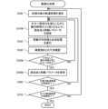
- 13 is a flowchart showing an example of a trajectory generation process.
- 11 is a flowchart showing an example of a base trajectory generation process.
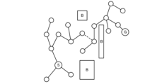
- FIG. 13 is a schematic diagram showing an example of a manner in which a trajectory is generated.
- FIG. 13 is a schematic diagram showing an example of a manner in which a trajectory is generated.
- FIG. 13 is a schematic diagram showing an example of a manner in which a trajectory is generated.
- FIG. 13 is a schematic diagram showing an example of a manner in which a trajectory is generated.
- 11 is a flowchart showing an example of an optimization process.
- 13 is a flowchart showing a base trajectory generation process according to a modified example.
- 13 is a flowchart showing an optimization process according to a modified example.
- FIG. 1 is a schematic diagram showing the configuration of a robot system 10.
- the robot system 10 includes a robot 20 and a trajectory generating device 40.
- the robot 20 is configured as, for example, a six-axis vertical articulated robot, and performs a predetermined task, such as picking up a workpiece (not shown) and placing it in a predetermined position.
- the robot 20 comprises a base 21 fixed to the workbench 11, a robot arm 22 including a plurality of links connected in series via six joint axes (first to sixth joint axes J1 to J6), and a control device 30 that controls the operation of the robot 20.
- the robot arm 22 is provided with servo motors 23a to 23f that rotate the first to sixth joint axes J1 to J6, respectively, and encoders (rotary encoders) 24a to 24f that detect the rotation angles of the servo motors 23a to 23f, respectively.
- the end effector 25 is detachably attached to the tip link of the robot arm 22 as a work tool, and a camera (not shown) can also be attached.
- the end effector 25 is composed of a suction nozzle that attracts the workpiece by negative pressure, a mechanical chuck that grips the workpiece with a pair of claws, an electromagnetic chuck that attracts the workpiece with an electromagnet, etc., and is appropriately selected according to the shape and material of the workpiece to be worked on.
- a mechanical chuck is shown as an example of the end effector 25.
- the end effector 25 is provided with an actuator 26 that drives the pair of claws 25a to open and close, an encoder (linear encoder) 27 that detects the open/close position of the actuator 26, and a gripping force sensor 28 that detects the gripping force of the claws 25a that grip the workpiece.
- an encoder linear encoder
- a gripping force sensor 28 that detects the gripping force of the claws 25a that grip the workpiece.
- the robot 20 also includes a power supply circuit 32 that converts AC power from a commercial power source (not shown) into DC power and supplies it to each part of the robot 20, and amplifiers 34a to 34f that drive the servo motors 23a to 23f with power from the power supply circuit 32.
- Each amplifier 34a to 34f drives each of the servo motors 23a to 23f by driving a switching element (not shown).
- the control device 30 is configured as a microprocessor centered around a CPU (not shown), and in addition to the CPU, it is equipped with ROM, RAM, an input/output interface, etc. Detection signals from the encoders 24a to 24f of the servo motors 23a to 23f, detection signals from the encoder 27 of the actuator 26, etc. are input to the control device 30.
- the control device 30 also outputs control signals to the amplifiers 34a to 34f, control signals to the actuator 26, etc.
- the control device 30 is also configured to be able to communicate with the trajectory generating device 40, and controls the drive of the robot arm 22 based on the trajectory generated by the trajectory generating device 40.
- the trajectory generating device 40 is a computer that includes a control device 41, a storage device 46, an input device 47, and a display device 48, and generates a trajectory for the robot arm 22 of the robot 20.
- the control device 41 is configured as a microprocessor centered around a CPU (not shown), and in addition to the CPU, includes ROM, RAM, an input/output interface, etc.
- the storage device 46 is configured, for example, by a HDD, and stores various data and programs required to generate the trajectory of the robot arm 22.
- the input device 47 is, for example, a keyboard, a mouse, etc., through which the operator performs input operations.
- the display device 48 is, for example, an LCD display, etc., that displays various information.
- the control device 41 includes a condition setting unit 42, a generation unit 43, an optimization unit 44, and an evaluation and selection unit 45 as functional blocks for generating a trajectory of the movement of the robot arm 22.
- the condition setting unit 42 sets various conditions such as constraint conditions at the time of trajectory generation, including conditions related to the hand of the robot arm 22. The various conditions may be set in advance, or conditions input by the operator via the input device 47 may be set.
- the generation unit 43 searches for waypoints from the start point S of the movement to the target point G by changing search parameters under the constraint conditions set by the condition setting unit 42, and generates a base trajectory that serves as the basis for evaluation and selection by the evaluation and selection unit 45, and trajectory candidates based on the base trajectory.
- the generation unit 43 uses, for example, an RRT-Connect-based search method that is an extension of the RRT method as a search method based on the RRT (Rapidly exploring Random Tree) method.
- the optimization unit 44 performs necessary trajectory adjustment and optimization on the base trajectory and trajectory candidates generated by the generation unit 43.
- the evaluation and selection unit 45 evaluates the trajectory that has been subjected to necessary trajectory adjustment and optimization by the optimization unit 44, and selects a trajectory based on the evaluation.
- the trajectory selected by the evaluation and selection unit 45 is transmitted to the robot 20, and the drive control of the robot arm 22 is performed based on the trajectory.
- the optimization unit 44 may also optimize the trajectory selected by the evaluation and selection unit 45.
- the trajectory generated in this manner is stored in the storage device 46.
- FIG. 2 is a flowchart showing an example of the trajectory generation process. This trajectory generation process is executed by the control device 41 of the trajectory generation device 40 using the functions of each of the functional blocks described above.
- the control device 41 first acquires various information related to the trajectory to be generated, such as the start point S and target point G of the movement in the joint angle space, information indicating the area of the obstacle B, and constraint conditions including conditions related to the hand of the robot arm 22 (S100).
- the start point S, target point G, waypoints between them, and information indicating the area of the obstacle B are expressed by the joint angles (movable angles) of each joint in the joint angle space, rather than by position coordinates in the XYZ space.
- the robot arm 22 Since the robot arm 22 has six joints, the first to sixth joint axes J1 to J6, the position information of each point, such as the start point S, target point G, and waypoints, in the joint angle space is expressed by the parameters of six joint angles. For this reason, even if it is possible to set a waypoint by searching for the position of the hand of the robot arm 22 in the XYZ space, it is possible to prevent problems such as going outside the movable angle range of the joint of the robot arm 22 while moving to the waypoint.
- various conditions based on the specifications of the robot 20 and the environment around the robot 20, such as the movable angle range of each joint, torque constraints, speed constraints, and acceleration constraints are defined as constraint conditions.
- a condition that the hand posture is a specified posture is defined as a condition related to the hand of the robot arm 22.
- the rotation angle (roll angle, pitch angle, yaw angle) around each axis in the XYZ space and its range are specified as the hand posture.
- Such conditions are specified when the end effector 25 of the robot arm 22 is operated while maintaining a constant orientation, such as facing downward.
- the control device 41 executes a base trajectory generation process (S110).
- the base trajectory generation process is a process that generates a base trajectory by searching for waypoints using an RRT-Connect-based search method.
- FIG. 3 is a flowchart showing an example of the base trajectory generation process.
- the control device 41 first searches for a tentative waypoint so as to satisfy the constraint conditions that do not interfere with obstacle B and result in a specified hand posture (specified posture) (S200).
- the control device 41 searches for a waypoint defined by parameters of six joint angles in the joint angle space so as to satisfy, for example, the rotation angle around each axis as the hand posture.
- the control device 41 then performs a process of interpolating up to a tentative waypoint so as to satisfy the constraint conditions for the specified posture (S210), and determines whether the interpolation was successful (S220). In S220, the control device 41 determines that the interpolation was successful if, when interpolating up to the tentative waypoint, the joint angle satisfies the specified posture and there is no interference with obstacle B. If the control device 41 determines that the interpolation was not successful, it returns to S200 and repeats the process.
- the control device 41 determines that the interpolation was successful, it retains the tentative via point as a via point (S230). That is, the control device 41 searches for a tentative via point that is the specified posture, and if the trajectory interpolated to the tentative via point at the specified posture does not interfere with an obstacle, it retains the tentative via point as a via point. Then, the control device 41 determines whether or not a via point to the target point G has been generated (S240). If the control device 41 determines that a via point to the target point G has not been generated, it returns to S200 and repeats the process. Also, if the control device 41 determines that a via point to the target point G has been generated, it connects the points to generate one base trajectory (S250), and ends the base trajectory generation process.
- FIGS. 4 to 8 are schematic diagrams showing an example of how a trajectory is generated. As described above, each point is represented in joint angle space, but for convenience of illustration, the schematic diagram is shown in a planar manner.
- the control device 41 starts generating via points from both the start point S side and the target point G side, for example, and can end the search when one via point on the start point S side and one via point on the target point G side can be connected by a straight line (dotted line in FIG. 4 and FIG. 5) and the specified posture is satisfied between both via points.
- the control device 41 can also change the search distance when searching for a tentative waypoint so as not to interfere with the obstacle B. Specifically, the control device 41 can change the search distance so that the longer the distance from the search source point to the obstacle B, the longer the search distance, and the shorter the distance from the search source point to the obstacle B, the shorter the search distance.
- the control device 41 first calculates the distance from the search source point to each obstacle B, and derives the shortest distance among them. For example, as shown in FIG.
- the control device 41 calculates the distance from the start point S to each obstacle B1, B2, and B3, and derives the distance to the obstacle B1 as the shortest distance among them, and searches for a tentative waypoint with a search distance D1 according to that distance. Note that in the search direction from the start point S toward the obstacle B1, the waypoint is searched so as not to interfere with the obstacle B1, and as a result, the search distance D1' is shorter than the search distance D1.
- the control device 41 searches for a tentative via point from the way point P in FIG. 6, the control device 41 calculates the distance from the way point P to each of the obstacles B1, B2, and B3, derives the distance to the obstacle B2 as the shortest distance, and searches for the tentative via point at a search distance D2 corresponding to that distance. Similarly, when the control device 41 searches for a tentative via point from the target point G, the control device 41 searches for the tentative via point at a search distance D3. Note that in the search direction from the target point G toward the obstacle B2, the tentative via point is searched for so as not to interfere with the obstacle B2, and as a result, the search distance D3' is shorter than the search distance D3. In FIG.
- the search distances D1, D2, and D3 are illustrated, but the search distance is set steplessly according to the distance from the search source to the obstacle B.
- the search distance may be set stepwise according to the distance from the search source to the obstacle B. In this way, by making the search distance variable, the control device 41 can efficiently search for and retain temporary waypoints, allowing the base trajectory to be generated quickly.
- the control device 41 searches for waypoints in this way and generates a base trajectory, for example the base trajectory R0 in FIG. 7. As shown in the figure, the control device 41 searches for waypoints (white circles) from the starting point S on the left to the target point G on the right, for example, so as not to interfere with the three obstacles B and to satisfy the constraint conditions for a specified posture, and generates a base trajectory R0 that connects each point.
- the position of the waypoint indicates, for example, the position of the hand of the robot arm 22.
- the interval between each point connected by a straight line is called a section.
- the control device 41 In the trajectory generation process of FIG. 2, the control device 41 generates multiple trajectory candidates based on the generated base trajectory (S120).
- multiple trajectory candidates are generated by randomly changing the waypoints of the base trajectory.
- the control device 41 when the control device 41 randomly changes the waypoints of the base trajectory to generate trajectory candidates, the control device 41 changes the waypoints so as to satisfy constraint conditions such as a specified attitude.
- each waypoint of the base trajectory R0 (dotted line) is changed to generate, for example, three trajectory candidates R1 to R3. Note that the control device 41 only needs to generate multiple trajectory candidates, and the trajectory candidates may include the base trajectory R0.
- the control device 41 executes an optimization process to optimize each of the multiple generated trajectory candidates (S130).
- FIG. 9 is a flowchart showing an example of the optimization process.
- the control device 41 selects one trajectory candidate to be processed (S300), and searches for the positions of each waypoint, for example by a gradient method, so as to shorten the operation time (travel time) on the trajectory candidate to be processed while satisfying the constraint conditions for the specified attitude (S310).
- the control device 41 is not limited to the gradient method, and may use other methods such as particle swarm optimization or a genetic algorithm.
- the control device 41 executes a moving average process and a synthesis process to set a command value for the operation of the robot arm 22 for the section including the waypoint whose position was searched for in S310 (S320).
- the moving average process is a process of deriving a command value by taking a moving average of the original speed for each calculation period in the section in order to make the speed change in each section gentler, for example.
- the original speed is set to a predetermined speed such as the maximum speed of the robot arm 22 under constraint conditions.
- the synthesis process is performed after the moving average process, and is a process of multiplying the command value of the previous section and the command value of the following section by a ratio (synthesis rate) respectively set so that the speed does not decrease in consecutive sections (connections between adjacent previous and following sections), and adding them up.
- synthesis rate ratio
- These processes are well known processes and will not be described in detail, but the trajectory after the synthesis process may have some parts that are inwardly oriented compared to the original trajectory generated initially, i.e., a trajectory connecting the waypoints with a straight line. Note that the speed, acceleration/deceleration, synthesis rate, etc. are called moving parameters.
- the control device 41 checks for interference with obstacle B in the trajectory candidate for which the moving average process and the synthesis process have been performed (S330), and judges whether the motion time is shorter without interference and the specified posture (constraint condition for the specified posture) is satisfied (S340). If the control device 41 judges in S340 that there is interference, that the motion time is not short, or that the specified posture is not satisfied, it returns to S310. When the control device 41 returns to S310, it executes the processes of S310 to S340, so that the process of searching for the position of each way point in the trajectory candidate to be processed so that the motion time is shorter without interference with obstacle B while satisfying the specified posture is repeated.
- the control device 41 judges in S340 that the motion time is shorter without interference and the specified posture is satisfied, it retains the way points searched for in S310 (S350).
- S350 the command value of the motion set in S320 is also retained together with the way points.
- the operation time at the stored waypoint is the shortest operation time at that time for the trajectory candidate, and is used as a comparison target for the operation time when the judgment of S340 is performed thereafter. Note that the process of optimizing the trajectory by searching for a waypoint that does not interfere with obstacle B and shortens the operation time is also called trajectory adjustment.
- the control device 41 judges whether the search for the trajectory candidates (each waypoint) to be processed has been completed based on whether a predetermined termination condition has been met (S360).
- the predetermined termination condition may be, for example, a condition that the number of executions (repetitions) of S310 to S350 has reached a predetermined number, or a condition that the gradient has converged to a predetermined range when the gradient method is used in S310. If the control device 41 judges in S360 that the search has not been completed, it returns to S310 and executes the processing from S310 onwards again. As described above, in S340, it is judged whether the operation time is shorter than the operation time based on the waypoints held in the previous S350.
- control device 41 judges in S360 that the search for the trajectory candidates to be processed has been completed, it judges whether the search for all the trajectory candidates has been completed (S370). If the search for all the trajectory candidates has not been completed, the control device 41 returns to S300, selects a trajectory candidate and performs processing. On the other hand, when the control device 41 determines in S370 that the search for all trajectory candidates has been completed, it ends the optimization process.
- the control device 41 executes an evaluation and selection process in which the optimized trajectory candidates are evaluated including the operation time (movement time) and a trajectory of the operation is selected based on the evaluation result (S140).
- the control device 41 selects, for example, one trajectory candidate with the shortest operation time as the trajectory of the operation.
- the control device 41 stores the selected trajectory in the storage device 46 (S150) and ends the trajectory generation process.
- the control device 41 also outputs the trajectory generated (selected) in the trajectory generation process to the control device 30 of the robot 20.
- the robot 20 stores the trajectory in the storage unit of the control device 30 and performs the drive control of the robot arm 22 based on the one or more generated trajectories to perform the above-mentioned predetermined work.
- the generated trajectory may be used for a simulation of the operation of the robot arm 22. That is, the generated trajectory is not limited to the actual operation of the robot 20 (robot arm 22), and may be used for evaluation and verification of the operation.
- the trajectory generation device 40 may also have a function of executing such a simulation.
- the control device 41 (generation unit 43) of the trajectory generation device 40 that executes S110 and S120 of the trajectory generation process of this embodiment corresponds to the generation unit of this disclosure
- the control device 41 (optimization unit 44) that executes S130 of the trajectory generation process corresponds to the optimization unit
- the control device 41 (evaluation selection unit 45) that executes S140 of the trajectory generation process corresponds to the evaluation selection unit.
- this embodiment also clarifies an example of the trajectory generation method of this disclosure by explaining the processing of the trajectory generation device 40.
- the trajectory generation device 40 (control device 41) of this embodiment described above searches for waypoints that satisfy constraint conditions including conditions related to the hand of the robot arm 22, and generates multiple trajectory candidates that connect each point so as to satisfy the constraint conditions.
- the position of the waypoint is searched for so as to shorten the movement time while satisfying the constraint conditions, and the movement time is evaluated, and the trajectory candidate with the shortest movement time is selected as the movement trajectory. Therefore, a trajectory that shortens the movement time while satisfying the conditions related to the hand can be quickly generated.
- the hand-related conditions include a condition that the hand posture of the robot arm 22 is a specified posture, and the trajectory generation device 40 searches for waypoints in the joint angle space so that the angles of each joint satisfy the hand posture. This makes it possible to quickly generate a trajectory that sets the hand posture to the specified posture. Furthermore, since the waypoints searched for in the joint angle space are in positions that the robot arm 22 can reach, it is possible to eliminate the need for an operator to adjust the positions of the waypoints.
- the trajectory generation device 40 also searches for a provisional via point that satisfies the constraint conditions in the joint angle space, and if it can successfully interpolate up to the provisional via point so as to satisfy the constraint conditions, it retains it as a via point and generates a base trajectory by connecting each point. This ensures that the constraint conditions are satisfied even between via points.
- the trajectory generation device 40 also generates multiple trajectory candidates by changing the positions of the via points in the base trajectory, so that trajectory candidates can be generated quickly.
- the search for the waypoint is started from both the start point S and the target point G, but this is not limited, and the search for the waypoint may be started from either the start point S or the target point G.
- the search distance is changed according to the distance to the obstacle B, but the search distance may be constant without changing it.
- the search method is not limited to the RRT-Connect based search method, and other search methods such as the RRT method and the potential method may be used.
- the temporary waypoint is searched in the joint angle space, but this is not limited, and the temporary waypoint may be searched in, for example, the XYZ space.
- the position of the waypoint in the base trajectory is randomly changed to generate multiple trajectory candidates, but multiple trajectory candidates may be generated by searching each of the waypoints.
- the trajectory candidate with the shortest operation time is selected as the trajectory of the operation, but this is not limited, and the trajectory of the operation may be selected based on the results of evaluation including the operation time, such as selecting a trajectory with the shortest operation time from among trajectory candidates without interference. For example, if the trajectory candidate has a relatively short operating time among multiple trajectory candidates, it may be selected based on the results of other evaluations, not necessarily the shortest trajectory.
- the other evaluations may be, for example, whether the trajectory candidate is far from an obstacle B with which interference needs to be reliably avoided.
- FIG. 10 is a flowchart showing a base trajectory generation process of the modified example.
- FIG. 11 is a flowchart showing an optimization process of the modified example.
- the same processes as those in the embodiment are given the same step numbers, and detailed explanations are omitted.
- a condition related to the hand of the robot arm 22 a condition is specified in which the gripping force with which the end effector 25 (jaw 25a) grips the workpiece (object) is greater than the external force acting on the workpiece (external force ⁇ gripping force).
- Such a condition is specified when it is necessary to reliably prevent the workpiece gripped by the end effector 25 from falling.
- Examples of external forces include gravity and inertial force.
- the inertial force is calculated from the acceleration and deceleration during the operation of the robot arm 22, i.e., during the movement of the workpiece.
- items that affect the external force such as the weight of the workpiece to be gripped, are set in advance or input by the operator via the input device 47, and are reflected in various calculations.
- the gripping force is, for example, the force with which the jaws 25a of the end effector 25 grip the workpiece, and is determined based on the specifications of the end effector 25. Note that the gripping force based on the detection value of the gripping force sensor 28 when the jaws 25a grip the workpiece may also be used. If the end effector 25 is a suction nozzle or electromagnetic chuck, an adhesive force due to negative pressure or an adhesive force due to electromagnetic force may be used. These adhesive forces and gripping forces are also referred to as holding forces.
- the control device 41 searches for a provisional via point and a provisional movement parameter so as to satisfy the constraint condition that the gripping force is greater than the external force without interfering with the obstacle B (S200b).
- the via point is searched in the joint angle space.
- the provisional movement parameter is a movement parameter such as the speed, acceleration/deceleration, and synthesis rate at the provisional via point.
- the control device 41 performs a process of interpolating to the provisional via point so as to satisfy the constraint condition that the gripping force is greater than the external force (S210b).
- the control device 41 derives the movement parameter of each interpolation point up to the provisional via point based on the provisional movement parameter, calculates the external force acting on the work based on the derived movement parameter, and compares it with the gripping force. If the control device 41 can interpolate so that the gripping force is greater than the external force at each interpolation point and there is no interference with the obstacle B, it determines in S220 that the interpolation has been successful. If the control device 41 determines that the interpolation was successful, it stores the temporary via points and temporary movement parameters as the via points and movement parameters (S230b).
- control device 41 when the control device 41 selects a candidate trajectory to be processed in S300, it searches for waypoints and movement parameters so that the operation time is shorter while satisfying the condition that the gripping force is greater than the external force (external force ⁇ gripping force) (S310b). The control device 41 then determines whether the condition that the operation time is shorter without interference with obstacle B and the gripping force is greater than the external force (external force ⁇ gripping force) is satisfied (S340b), and if it determines that the condition is satisfied, it retains the waypoints and movement parameters searched for in S310b (S350b).
- the hand condition includes a condition that the gripping force (holding force) of the end effector 25 of the robot arm 22 is greater than the external force acting on the workpiece.
- the trajectory generation device 40 searches for waypoints and movement parameters that satisfy this condition in the joint angle space, so that it can quickly generate a trajectory in which the gripping force is greater than the external force.
- the trajectory generation device 40 searches for temporary waypoints and temporary movement parameters that satisfy the constraint conditions in the joint angle space, and when it is able to interpolate up to the temporary waypoint so as to satisfy the constraint conditions, it generates a base trajectory by connecting each point while retaining them as waypoints and movement parameters. Therefore, it is possible to reliably satisfy the constraint conditions even between waypoints. Furthermore, since multiple trajectory candidates are generated by changing the positions of the waypoints and the movement parameters in the base trajectory, it is possible to quickly generate trajectory candidates.
- condition regarding the hand of the robot arm 22 is a condition that the hand posture is specified in the embodiment, and a condition that the gripping force is greater than the external force in the modified example, but these are not limited to being determined separately.
- the condition regarding the hand of the robot arm 22 may be a condition that the hand posture is specified and the gripping force is greater than the external force.
- the condition regarding the hand of the robot arm 22 may be another condition regarding the hand, such as a size based on the open/closed state of the hand.
- a six-axis vertical articulated robot is exemplified, but the present invention is not limited to this and may be a five-axis or other vertical articulated robot, or a horizontal articulated robot.
- the trajectory generation device 40 generates the trajectory, but the control device 30 of the robot 20 may generate the trajectory.
- the trajectory generation device 40 and the control device 30 may work together to generate the trajectory.
- This disclosure can be used in the technical field of generating trajectories for multi-joint robot arms.
Landscapes
- Engineering & Computer Science (AREA)
- Robotics (AREA)
- Mechanical Engineering (AREA)
- Manipulator (AREA)
Priority Applications (2)
| Application Number | Priority Date | Filing Date | Title |
|---|---|---|---|
| JP2024571495A JPWO2024154249A1 (https=) | 2023-01-18 | 2023-01-18 | |
| PCT/JP2023/001319 WO2024154249A1 (ja) | 2023-01-18 | 2023-01-18 | 軌道生成装置および軌道生成方法 |
Applications Claiming Priority (1)
| Application Number | Priority Date | Filing Date | Title |
|---|---|---|---|
| PCT/JP2023/001319 WO2024154249A1 (ja) | 2023-01-18 | 2023-01-18 | 軌道生成装置および軌道生成方法 |
Publications (1)
| Publication Number | Publication Date |
|---|---|
| WO2024154249A1 true WO2024154249A1 (ja) | 2024-07-25 |
Family
ID=91955696
Family Applications (1)
| Application Number | Title | Priority Date | Filing Date |
|---|---|---|---|
| PCT/JP2023/001319 Ceased WO2024154249A1 (ja) | 2023-01-18 | 2023-01-18 | 軌道生成装置および軌道生成方法 |
Country Status (2)
| Country | Link |
|---|---|
| JP (1) | JPWO2024154249A1 (https=) |
| WO (1) | WO2024154249A1 (https=) |
Cited By (1)
| Publication number | Priority date | Publication date | Assignee | Title |
|---|---|---|---|---|
| CN119902489A (zh) * | 2025-03-27 | 2025-04-29 | 河北恒工精密装备股份有限公司 | 基于五轴加工中心的整体式叶轮加工方法、装置及设备 |
Citations (6)
| Publication number | Priority date | Publication date | Assignee | Title |
|---|---|---|---|---|
| US20130238132A1 (en) * | 2010-11-24 | 2013-09-12 | Kuka Roboter Gmbh | Method And Device For Controlling A Peripheral Component Of A Robot System |
| JP2014193519A (ja) * | 2013-03-28 | 2014-10-09 | Denso Wave Inc | 多軸型ロボットの軌道生成方法及び多軸型ロボットの制御装置 |
| WO2018092860A1 (ja) * | 2016-11-16 | 2018-05-24 | 三菱電機株式会社 | 干渉回避装置 |
| WO2018143003A1 (ja) * | 2017-01-31 | 2018-08-09 | 株式会社安川電機 | ロボットパス生成装置及びロボットシステム |
| JP2020049554A (ja) * | 2018-09-21 | 2020-04-02 | キヤノン株式会社 | 軌道生成方法、軌道生成装置、およびロボットシステム |
| JP2021079482A (ja) * | 2019-11-19 | 2021-05-27 | 株式会社日立製作所 | 軌道計画生成装置、軌道計画生成方法、および軌道計画生成プログラム |
-
2023
- 2023-01-18 JP JP2024571495A patent/JPWO2024154249A1/ja active Pending
- 2023-01-18 WO PCT/JP2023/001319 patent/WO2024154249A1/ja not_active Ceased
Patent Citations (6)
| Publication number | Priority date | Publication date | Assignee | Title |
|---|---|---|---|---|
| US20130238132A1 (en) * | 2010-11-24 | 2013-09-12 | Kuka Roboter Gmbh | Method And Device For Controlling A Peripheral Component Of A Robot System |
| JP2014193519A (ja) * | 2013-03-28 | 2014-10-09 | Denso Wave Inc | 多軸型ロボットの軌道生成方法及び多軸型ロボットの制御装置 |
| WO2018092860A1 (ja) * | 2016-11-16 | 2018-05-24 | 三菱電機株式会社 | 干渉回避装置 |
| WO2018143003A1 (ja) * | 2017-01-31 | 2018-08-09 | 株式会社安川電機 | ロボットパス生成装置及びロボットシステム |
| JP2020049554A (ja) * | 2018-09-21 | 2020-04-02 | キヤノン株式会社 | 軌道生成方法、軌道生成装置、およびロボットシステム |
| JP2021079482A (ja) * | 2019-11-19 | 2021-05-27 | 株式会社日立製作所 | 軌道計画生成装置、軌道計画生成方法、および軌道計画生成プログラム |
Cited By (1)
| Publication number | Priority date | Publication date | Assignee | Title |
|---|---|---|---|---|
| CN119902489A (zh) * | 2025-03-27 | 2025-04-29 | 河北恒工精密装备股份有限公司 | 基于五轴加工中心的整体式叶轮加工方法、装置及设备 |
Also Published As
| Publication number | Publication date |
|---|---|
| JPWO2024154249A1 (https=) | 2024-07-25 |
Similar Documents
| Publication | Publication Date | Title |
|---|---|---|
| EP2835228B1 (en) | Robot apparatus and robot controlling method | |
| KR101645091B1 (ko) | 로봇 시스템 및 피가공물의 제조 방법 | |
| JP2006236031A (ja) | ロボット軌跡制御方法及び装置並びにロボット軌跡制御方法のプログラム | |
| US11433537B2 (en) | Automatic path generation device | |
| CN112703090B (zh) | 机器人控制装置、机器人控制方法及存储介质 | |
| JP6170285B2 (ja) | マニピュレータ及びその経路生成方法 | |
| US20110224815A1 (en) | Industrial Robot And Path Planning Method For Controlling The Movement Of An Industrial Robot | |
| JP2014180704A (ja) | ロボットピッキングシステム及び被加工物の製造方法 | |
| WO2020149021A1 (ja) | 経路生成装置、経路生成方法、及び経路生成プログラム | |
| JP2018114607A (ja) | ロボット制御装置、ロボットシステム、ロボット制御方法、プログラム、記録媒体及び物品の製造方法 | |
| JP2019018272A (ja) | モーション生成方法、モーション生成装置、システム及びコンピュータプログラム | |
| JP2019063912A (ja) | ロボット制御データ処理方法、ロボット制御データ処理装置、およびロボットシステム | |
| US20210245364A1 (en) | Method And Control System For Controlling Movement Trajectories Of A Robot | |
| JP6697544B2 (ja) | 最適化装置及びそれを備えた垂直型多関節ロボット | |
| JP5144035B2 (ja) | 産業用ロボットのツールの位置・姿勢制御方法及び制御システム | |
| CN114643581A (zh) | 基于改进人工势场法的双机械臂避碰轨迹规划方法及系统 | |
| WO2024154249A1 (ja) | 軌道生成装置および軌道生成方法 | |
| WO2022201377A1 (ja) | ロボット制御装置およびロボット制御方法 | |
| JP4528577B2 (ja) | 工業用ロボット | |
| JP4970492B2 (ja) | 多関節ロボット | |
| WO2024154250A1 (ja) | 軌道生成装置および軌道生成方法 | |
| WO2024154247A1 (ja) | 軌道生成装置および軌道生成方法 | |
| JP2007066001A (ja) | ロボットの制御装置 | |
| JP4647919B2 (ja) | 制御方法および制御装置 | |
| JP2019214105A (ja) | ロボット制御装置およびロボット制御方法 |
Legal Events
| Date | Code | Title | Description |
|---|---|---|---|
| 121 | Ep: the epo has been informed by wipo that ep was designated in this application |
Ref document number: 23917463 Country of ref document: EP Kind code of ref document: A1 |
|
| WWE | Wipo information: entry into national phase |
Ref document number: 2024571495 Country of ref document: JP |
|
| NENP | Non-entry into the national phase |
Ref country code: DE |
|
| 122 | Ep: pct application non-entry in european phase |
Ref document number: 23917463 Country of ref document: EP Kind code of ref document: A1 |