WO2024154246A1 - 熱交換器および冷凍サイクル装置 - Google Patents
熱交換器および冷凍サイクル装置 Download PDFInfo
- Publication number
- WO2024154246A1 WO2024154246A1 PCT/JP2023/001310 JP2023001310W WO2024154246A1 WO 2024154246 A1 WO2024154246 A1 WO 2024154246A1 JP 2023001310 W JP2023001310 W JP 2023001310W WO 2024154246 A1 WO2024154246 A1 WO 2024154246A1
- Authority
- WO
- WIPO (PCT)
- Prior art keywords
- flow path
- refrigerant
- header
- heat exchanger
- spatial flow
- Prior art date
- Legal status (The legal status is an assumption and is not a legal conclusion. Google has not performed a legal analysis and makes no representation as to the accuracy of the status listed.)
- Ceased
Links
Images






Classifications
-
- F—MECHANICAL ENGINEERING; LIGHTING; HEATING; WEAPONS; BLASTING
- F28—HEAT EXCHANGE IN GENERAL
- F28D—HEAT-EXCHANGE APPARATUS, NOT PROVIDED FOR IN ANOTHER SUBCLASS, IN WHICH THE HEAT-EXCHANGE MEDIA DO NOT COME INTO DIRECT CONTACT
- F28D1/00—Heat-exchange apparatus having stationary conduit assemblies for one heat-exchange medium only, the media being in contact with different sides of the conduit wall, in which the other heat-exchange medium is a large body of fluid, e.g. domestic or motor car radiators
- F28D1/02—Heat-exchange apparatus having stationary conduit assemblies for one heat-exchange medium only, the media being in contact with different sides of the conduit wall, in which the other heat-exchange medium is a large body of fluid, e.g. domestic or motor car radiators with heat-exchange conduits immersed in the body of fluid
- F28D1/04—Heat-exchange apparatus having stationary conduit assemblies for one heat-exchange medium only, the media being in contact with different sides of the conduit wall, in which the other heat-exchange medium is a large body of fluid, e.g. domestic or motor car radiators with heat-exchange conduits immersed in the body of fluid with tubular conduits
- F28D1/053—Heat-exchange apparatus having stationary conduit assemblies for one heat-exchange medium only, the media being in contact with different sides of the conduit wall, in which the other heat-exchange medium is a large body of fluid, e.g. domestic or motor car radiators with heat-exchange conduits immersed in the body of fluid with tubular conduits the conduits being straight
-
- F—MECHANICAL ENGINEERING; LIGHTING; HEATING; WEAPONS; BLASTING
- F28—HEAT EXCHANGE IN GENERAL
- F28F—DETAILS OF HEAT-EXCHANGE AND HEAT-TRANSFER APPARATUS, OF GENERAL APPLICATION
- F28F9/00—Casings; Header boxes; Auxiliary supports for elements; Auxiliary members within casings
- F28F9/02—Header boxes; End plates
Definitions
- An embodiment of the present invention relates to a heat exchanger and a refrigeration cycle device.
- Heat exchangers are used in air conditioners, refrigeration equipment, and the like.
- a heat exchanger includes multiple heat exchange tubes and a header.
- the heat exchange tubes have a refrigerant flow path.
- the header is provided at the end of the heat exchange tube.
- a heat exchanger with the above structure could potentially result in low heat exchange efficiency.
- the problem that this invention aims to solve is to provide a heat exchanger and a refrigeration cycle device that are capable of efficient heat exchange.
- the heat exchanger of the embodiment has a plurality of heat transfer tubes, a first header, and a second header.
- the heat transfer tubes have a refrigerant flow path through which a refrigerant flows.
- the heat transfer tubes have a flat shape.
- the heat transfer tubes are arranged in parallel.
- the first header is connected to one end of the plurality of heat transfer tubes.
- the second header is connected to the other end of the plurality of heat transfer tubes.
- the first header has a first intermediate plate, a first inner end plate, and a first outer end plate.
- the first intermediate plate has one or more first spatial flow paths formed therein that communicate with the refrigerant flow paths of adjacent heat transfer tubes.
- the first inner end plate and the first outer end plate sandwich the first intermediate plate in the thickness direction.
- the second header has a second intermediate plate, a second inner end plate, and a second outer end plate.
- the second intermediate plate has one or more second spatial flow paths formed therein that communicate with the refrigerant flow paths of adjacent heat transfer tubes.
- the second inner end plate and the second outer end plate sandwich the second intermediate plate in the thickness direction.
- the refrigerant flow path, the first spatial flow path, and the second spatial flow path form multiple combined flow paths.
- the combined flow paths are formed by alternately connecting one end and the other end of the refrigerant flow paths of the multiple heat transfer tubes with the first spatial flow path and the second spatial flow path.
- FIG. 1 is a schematic configuration diagram of a refrigeration cycle device according to an embodiment
- FIG. 2 is an overall configuration diagram of a heat exchanger according to the first embodiment.
- FIG. 2 is a perspective view of a portion of the heat exchanger of the first embodiment.
- FIG. 2 is an exploded perspective view of a portion of the heat exchanger of the first embodiment.
- FIG. 7 is an overall configuration diagram of a heat exchanger according to a second embodiment.
- FIG. 13 is an overall configuration diagram of a heat exchanger according to a third embodiment.
- FIG. 13 is a schematic configuration diagram of a first modified example of a header.
- FIG. 13 is a schematic configuration diagram of a second modified example of a header.
- FIG. 13 is a schematic configuration diagram of a third modified example of a header.
- FIG. 13 is a schematic configuration diagram of a fourth modified example of a header.
- FIG. 1 is a schematic diagram of a refrigeration cycle device according to an embodiment.
- the refrigeration cycle apparatus 1 includes a compressor 2, a four-way valve 3, an outdoor heat exchanger (heat exchanger) 4, an expansion device 5, and an indoor heat exchanger (heat exchanger) 6.
- the components of the refrigeration cycle apparatus 1 are connected by piping 7.
- the flow direction of the refrigerant (heat medium) during cooling operation is indicated by solid arrows, and the flow direction of the refrigerant during heating operation is indicated by dashed arrows.
- the compressor 2 comprises a compressor body 2A and an accumulator 2B.
- the compressor body 2A compresses the low-pressure gas refrigerant taken in to produce high-temperature, high-pressure gas refrigerant.
- the accumulator 2B separates the gas-liquid two-phase refrigerant and supplies the gas refrigerant to the compressor body 2A.
- the four-way valve 3 reverses the flow direction of the refrigerant to switch between cooling and heating operation.
- the refrigerant flows through the compressor 2, four-way valve 3, outdoor heat exchanger 4, expansion device 5, and indoor heat exchanger 6 in that order.
- the outdoor heat exchanger 4 functions as a condenser.
- the indoor heat exchanger 6 functions as an evaporator.
- the refrigerant flows through the compressor 2, four-way valve 3, indoor heat exchanger 6, expansion device 5, and outdoor heat exchanger 4 in that order.
- the indoor heat exchanger 6 functions as a condenser.
- the outdoor heat exchanger 4 functions as an evaporator.
- the condenser converts the high-temperature, high-pressure gas refrigerant discharged from the compressor 2 into high-pressure liquid refrigerant by condensing it through heat transfer to the outside air.
- the expansion device 5 reduces the pressure of the high-pressure liquid refrigerant sent from the condenser, converting it into a low-temperature, low-pressure two-phase gas-liquid refrigerant.
- the evaporator converts the low-temperature, low-pressure two-phase gas-liquid refrigerant sent from the expansion device 5 into a low-pressure gas refrigerant by absorbing heat from the outside air and vaporizing it.
- the refrigerant which is the working fluid, circulates while changing phase between gaseous refrigerant and liquid refrigerant.
- the refrigerant releases heat during the phase change from gaseous refrigerant to liquid refrigerant.
- the refrigerant absorbs heat during the phase change from liquid refrigerant to gaseous refrigerant.
- the refrigeration cycle device 1 uses the heat release or absorption of the refrigerant to perform heating, cooling, defrosting, etc.
- FIG. 2 is an overall configuration diagram of a heat exchanger of the first embodiment.
- the heat exchanger of the embodiment is used as one or both of the outdoor heat exchanger 4 and the indoor heat exchanger 6 (see FIG. 1) of the refrigeration cycle device 1.
- the heat exchanger of the embodiment is used as the outdoor heat exchanger 4 (see FIG. 1) of the refrigeration cycle device 1.
- the outdoor heat exchanger 4 will be simply referred to as "heat exchanger 4.”
- the heat exchanger 4 includes a plurality of heat exchangers 104.
- the plurality of heat exchangers 104 includes a first heat exchanger 104A, a second heat exchanger 104B, and a third heat exchanger 104C.
- FIG. 2 shows a simplified representation of the structure of the heat exchanger 104.
- the heat exchangers 104 are connected to an inlet flow path 101 and an outlet flow path 102.
- the inlet flow path 101 includes a supply flow path 111, a distributor 112, a first inlet flow path 113, a second inlet flow path 114, and a third inlet flow path 115.
- the supply flow path 111 branches into three flow paths (the first inlet flow path 113, the second inlet flow path 114, and the third inlet flow path 115).
- the distributor 112 distributes the refrigerant from the supply flow path 111 to the first inlet flow path 113, the second inlet flow path 114, and the third inlet flow path 115.
- the first inlet flow passage 113 is connected to the inlet of the first heat exchanger 104A.
- the second inlet flow passage 114 is connected to the inlet of the second heat exchanger 104B.
- the third inlet flow passage 115 is connected to the inlet of the third heat exchanger 104C.
- the inlet is an opening of the first refrigerant port connected to the first through hole 42 that leads to the spatial flow passage 16A (see FIG. 3).
- the outlet flow path 102 includes a first outlet flow path 123, a second outlet flow path 124, a third outlet flow path 125, and a collecting flow path 121.
- One end of the first outlet flow path 123 is connected to the outlet of the first heat exchanger 104A.
- One end of the second outlet flow path 124 is connected to the outlet of the second heat exchanger 104B.
- One end of the third outlet flow path 125 is connected to the outlet of the third heat exchanger 104C.
- the outlet is an opening of the second refrigerant port connected to the second through hole 43 that leads to the spatial flow path 16E (see FIG. 3).
- the other ends of the first outlet flow path 123, the second outlet flow path 124, and the third outlet flow path 125 are connected to the collecting flow path 121. Therefore, the refrigerant discharged from the first outlet flow path 123, the second outlet flow path 124, and the third outlet flow path 125 can be collected in the collecting flow path 121 and discharged outside the system.
- the X direction, Y direction, and Z direction are defined as follows:
- the Z direction is the longitudinal direction (extension direction) of the first header and the second header.
- the +Z direction is the upward direction.
- the X direction is the central axis direction (extension direction) of the heat exchange tube.
- the X direction is the horizontal direction.
- the +X direction is the direction from the second header to the first header.
- the Y direction is the direction perpendicular to the X direction and the Z direction.
- the YZ plane is a plane formed by the Y direction and the Z direction.
- the heat exchanger 104 has a first header 10 , a second header 20 , and a plurality of heat exchange tubes (heat transfer tubes) 30 .
- the first header 10 is connected to the +X direction end (one end) of the heat exchange tube 30.
- the second header 20 is connected to the ⁇ X direction end (the other end) of the heat exchange tube 30.
- the first header 10 and the second header 20 are formed in a flat plate shape parallel to the YZ plane.
- the first header 10 and the second header 20 are rectangular when viewed from the X direction.
- the first header 10 and the second header 20 are shaped like a rectangle with the longitudinal direction along the Z direction.
- the first header 10 and the second header 20 are formed from a material with high thermal conductivity and low specific gravity. Examples of materials with high thermal conductivity and low specific gravity include metals such as aluminum and aluminum alloys.
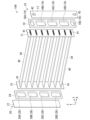
- FIG. 4 is an exploded perspective view of the heat exchanger 104.
- the first header 10 includes a first inner end plate 11, a first intermediate plate 14, and a first outer end plate 17.
- the first inner end plate 11 and the first outer end plate 17 sandwich the first intermediate plate 14 in the thickness direction.
- the first inner end plate 11 is disposed on the inner surface (second surface) of the first intermediate plate 14. That is, the first inner end plate 11 is overlapped on the surface (second surface) of the first intermediate plate 14 on the -X direction side.
- the first outer end plate 17 is disposed on the outer surface (first surface) of the first intermediate plate 14. That is, the first outer end plate 17 is overlapped on the surface (first surface) of the first intermediate plate 14 on the +X direction side.
- the first inner end plate 11, the first intermediate plate 14, and the first outer end plate 17 are rectangular.
- the first intermediate plate 14 has multiple spatial flow paths 16 (16A-16E) (first spatial flow paths).
- the spatial flow paths 16 serve as flow paths for the refrigerant.
- the spatial flow paths 16 are formed by through holes that penetrate the first intermediate plate 14 in the thickness direction.
- the openings on the inner surface side of the spatial flow paths 16 are closed by the first inner end plate 11.
- the openings on the outer surface side of the spatial flow paths 16 are closed by the first outer end plate 17.
- the multiple spatial flow paths 16 include spatial flow paths 16A to 16E.
- Spatial flow path 16A has an elliptical shape when viewed from the X direction.
- An "elliptical shape” is a shape consisting of two straight lines that are parallel and facing each other, and curved convex curves (e.g. semicircular, elliptical arc, etc.) that connect the ends of the two straight lines.
- the major axis direction of spatial flow path 16A is parallel to the Y direction.
- Spatial flow paths 16B to 16D are rectangular when viewed from the X direction.
- spatial flow paths 16B to 16D are rounded quadrangles (rectangles with rounded corners).
- Spatial flow path 16E is oval when viewed from the X direction. The major axis of spatial flow path 16E is parallel to the Y direction.
- the spatial flow channels 16A to 16E are arranged side by side in the Z direction.
- the spatial flow channel 16A is at the highest position among the spatial flow channels 16A to 16E (i.e., it is located furthest in the +Z direction).
- the spatial flow channel 16E is at the lowest position among the spatial flow channels 16A to 16E (i.e., it is located furthest in the -Z direction).
- the first inner end plate 11 has one through hole 41 formed at a position corresponding to spatial flow path 16A.
- the first inner end plate 11 has two through holes 41, 41 formed at positions corresponding to spatial flow paths 16B to 16D.
- the two through holes 41, 41 are formed with a gap in the Z direction.
- the first inner end plate 11 has one through hole 41 formed at a position corresponding to spatial flow path 16E.
- the through-hole 41 is a slit along the Y direction.
- the +X-direction end of the heat exchange tube 30 is inserted into the through-hole 41.
- the +X-direction end of the heat exchange tube 30 opens into the spatial flow path 16 of the first intermediate plate 14.
- the first outer end plate 17 has a first through hole 42 formed at a position corresponding to the spatial flow path 16A.
- the first through hole 42 is circular.
- a tubular first refrigerant port is inserted into the first through hole 42.
- the first refrigerant port has a flow passage through which the refrigerant flows.
- An end of the first refrigerant port opens into the spatial flow path 16A. This opening serves as an inlet (inlet) for introducing the refrigerant into the heat exchanger 104, or an outlet (outlet) for discharging the refrigerant from the heat exchanger 104.
- a second through hole 43 is formed in the first outer end plate 17 at a position corresponding to the spatial flow path 16E.
- the second through hole 43 is circular.
- a tubular second refrigerant port is inserted into the second through hole 43.
- the second refrigerant port has a flow passage through which the refrigerant flows.
- An end of the second refrigerant port opens into the spatial flow path 16E. This opening serves as an inlet for introducing the refrigerant into the heat exchanger 104, or an outlet for discharging the refrigerant from the heat exchanger 104.
- the spatial flow path 16A serves as an introduction spatial flow path through which the refrigerant is introduced.
- the spatial flow path 16A serves as an outlet spatial flow path through which the refrigerant is discharged.
- the spatial flow path 16E serves as an introduction spatial flow path through which the refrigerant is introduced.
- the spatial flow path 16E serves as an outlet spatial flow path through which the refrigerant is discharged.
- the second header 20 comprises a second inner end plate 21, a second intermediate plate 24, and a second outer end plate 27.
- the second inner end plate 21 and the second outer end plate 27 sandwich the second intermediate plate 24 in the thickness direction.
- the second inner end plate 21 is disposed on the inner surface side of the second intermediate plate 24. That is, the second inner end plate 21 is superimposed on the surface of the second intermediate plate 24 on the +X direction side.
- the second outer end plate 27 is disposed on the outer surface side of the second intermediate plate 24. That is, the second outer end plate 27 is superimposed on the surface of the second intermediate plate 24 on the -X direction side.
- the second inner end plate 21, the second intermediate plate 24, and the second outer end plate 27 are rectangular.
- the second intermediate plate 24 has multiple spatial flow paths 26 (26A-26D) (second spatial flow paths).
- the spatial flow paths 26 serve as flow paths for the refrigerant.
- the spatial flow paths 26 are formed by through holes that penetrate the second intermediate plate 24 in the thickness direction.
- the openings on the inner surface side of the spatial flow paths 26 are closed by the second inner end plate 21.
- the openings on the outer surface side of the spatial flow paths 26 are closed by the second outer end plate 27.
- the multiple spatial channels 26 include spatial channels 26A to 26D.
- the spatial channels 26A to 26D are rectangular when viewed from the X direction.
- the spatial channels 26A to 26D are rectangular with rounded corners (rectangles with rounded corners).
- the spatial flow channels 26A to 26D are arranged side by side in the Z direction.
- the spatial flow channel 26A is at the highest position among the spatial flow channels 26A to 26D (i.e., it is located furthest in the +Z direction).
- the spatial flow channel 26D is at the lowest position among the spatial flow channels 26A to 26D (i.e., it is located furthest in the -Z direction).
- Two through holes 41, 41 are formed in the second inner end plate 21 at positions corresponding to the spatial flow paths 26A to 26D.
- the two through holes 41, 41 are formed spaced apart in the Z direction.
- the through-holes 41 are slit-shaped along the Y direction.
- the ⁇ X direction ends of the heat exchange tubes 30 are inserted into the through-holes 41.
- the ⁇ X direction ends of the heat exchange tubes 30 open into the spatial flow paths 26 of the second intermediate plate 24.
- the heat exchange tube 30 is a flat tube formed in a flat shape.
- the heat exchange tube 30 has a larger outer dimension (outer diameter) in the Y direction than the outer dimension (outer diameter) in the Z direction.
- the heat exchange tube 30 has a larger inner dimension (inner diameter) in the Y direction than the inner dimension (inner diameter) in the Z direction.
- the outer dimension (outer diameter) of the heat exchange tube 30 in the Y direction is more than twice the inner dimension (inner diameter) in the Z direction.
- the inner dimension (inner diameter) of the heat exchange tube 30 in the Y direction is more than twice the inner dimension (inner diameter) in the Z direction.
- the shape of the cross section (YZ cross section) of the heat exchange tube 30 perpendicular to the length direction is an ellipse.
- the heat exchange tube 30 extends in the X direction.
- a refrigerant flow path 34 is formed inside the heat exchange tube 30.
- a refrigerant flows through the refrigerant flow path 34.
- the heat exchange tube 30 is made of a material that has high thermal conductivity and low specific gravity. Examples of "materials that have high thermal conductivity and low specific gravity" include metals such as aluminum and aluminum alloys.
- the heat exchange tubes 30 are arranged in parallel with intervals in the Z direction.
- the +X-direction ends of the heat exchange tubes 30 are inserted into the through holes 41 formed in the first header 10.
- the +X-direction ends of the refrigerant flow paths 34 of the heat exchange tubes 30 open into the spatial flow paths 16 of the first header 10. Therefore, the spatial flow paths 16 communicate with the refrigerant flow paths 34 of the heat exchange tubes 30.
- the -X direction end of the heat exchange tube 30 is inserted into the through hole 41 formed in the second header 20.
- the -X direction end of the refrigerant flow path 34 of the heat exchange tube 30 opens into the spatial flow path 26 of the second header 20. Therefore, the spatial flow path 26 communicates with the refrigerant flow path 34 of the heat exchange tube 30.
- the gap between the first header 10 and the heat exchange tubes 30 is sealed, for example, by brazing.
- the gap between the second header 20 and the heat exchange tubes 30 is sealed, for example, by brazing.
- an outside air flow path is formed along the Y direction.
- the heat exchanger 4 circulates outside air through the outside air flow path by means of a blower fan (not shown) or the like.
- the heat exchanger 4 exchanges heat between the outside air flowing through the outside air flow path and the refrigerant flowing through the refrigerant flow path 34.
- the heat exchange is performed indirectly via the heat exchange tubes 30.
- the outdoor heat exchanger 4 functions as a condenser.
- the gaseous refrigerant flowing out of the compressor 2 flows into the outdoor heat exchanger 4.
- the gaseous refrigerant releases heat to the outside air and condenses as it flows through the heat exchange tube 30.
- the condensed refrigerant becomes a liquid refrigerant and flows out of the system.
- the refrigerant flows in the opposite direction to the above.
- the liquid refrigerant flows into the outdoor heat exchanger 4.
- the heat exchange tube 30 As the liquid refrigerant flows through the heat exchange tube 30, some of it evaporates and becomes a two-phase gas-liquid refrigerant, which flows out of the system.
- the refrigerant flows into the first header 10 through one of the first refrigerant port and the second refrigerant port.
- the refrigerant that flows from the first refrigerant port into the spatial flow path 16A flows through the heat exchange tubes 30 (30A) in the -X direction and flows into the upper part of the spatial flow path 26A of the second header 20.
- the refrigerant flows from the lower part of the spatial flow path 26A in the +X direction through the heat exchange tubes 30 (30B) and flows into the upper part of the spatial flow path 16B of the first header 10.
- the refrigerant flows from the lower part of the spatial flow path 16B in the -X direction through the heat exchange tubes 30 (30C) and flows into the upper part of the spatial flow path 26B of the second header 20.
- the refrigerant flows from the lower part of the spatial flow path 26B through the heat exchange tube 30 (30D) in the +X direction and flows into the upper part of the spatial flow path 16C of the first header 10.
- the refrigerant flows from the lower part of the spatial flow path 16C through the heat exchange tube 30 (30E) in the -X direction and flows into the upper part of the spatial flow path 26C of the second header 20.
- the refrigerant flows from the lower part of the spatial flow path 26C through the heat exchange tube 30 (30F) in the +X direction and flows into the upper part of the spatial flow path 16D of the first header 10.
- the refrigerant flows from the lower part of the spatial flow path 16D through the heat exchange tube 30 (30G) in the -X direction and flows into the upper part of the spatial flow path 26D of the second header 20.
- the refrigerant flows from the lower part of the spatial flow path 26D through the heat exchange tube 30 (30H) in the +X direction and flows into the spatial flow path 16E of the first header 10.
- the refrigerant flows out from the spatial flow path 16E through the second refrigerant port.
- the refrigerant that flows from the second refrigerant port into the spatial flow path 16E flows through the heat exchange tube 30 (30H) in the -X direction and into the lower part of the spatial flow path 26D of the second header 20.
- the refrigerant flows from the upper part of the spatial flow path 26D in the +X direction through the heat exchange tube 30 (30G) and into the lower part of the spatial flow path 16D of the first header 10.
- the refrigerant flows from the upper part of the spatial flow path 16D in the -X direction through the heat exchange tube 30 (30F) and into the lower part of the spatial flow path 26C of the second header 20.
- the refrigerant flows from the top of the spatial flow path 26C through the heat exchange tube 30 (30E) in the +X direction and into the bottom of the spatial flow path 16C of the first header 10.
- the refrigerant flows from the top of the spatial flow path 16C through the heat exchange tube 30 (30D) in the -X direction and into the bottom of the spatial flow path 26B of the second header 20.
- the refrigerant flows from the top of the spatial flow path 26B through the heat exchange tube 30 (30C) in the +X direction and into the bottom of the spatial flow path 16B of the first header 10.
- the refrigerant flows from the top of the spatial flow path 16B through the heat exchange tube 30 (30B) in the -X direction and into the bottom of the spatial flow path 26A of the second header 20.
- the refrigerant flows from the top of the spatial flow path 26A through the heat exchange tube 30 (30A) in the +X direction and into the spatial flow path 16A of the first header 10.
- the refrigerant flows out from the spatial flow path 16A through the first refrigerant port.
- the spatial flow path 16 (first spatial flow path) of the first header 10, the spatial flow path 26 (second spatial flow path) of the second header 20, and the refrigerant flow path 34 of the heat exchange tube 30 constitute a combined flow path 40.
- the combined flow path 40 is a serpentine-shaped flow path that travels back and forth between the first header 10 and the second header 20.
- the composite flow path 40 is formed by the spatial flow path 16 and the spatial flow path 26 alternately connecting one end and the other end of the refrigerant flow paths 34 of the multiple heat exchange tubes 30.
- the spatial flow path 16 connects the +X direction ends (one ends) of the refrigerant flow paths 34 of two adjacent heat exchange tubes 30.
- the spatial flow path 26 connects the -X direction ends (other ends) of the refrigerant flow paths 34 of two adjacent heat exchange tubes 30.
- the spatial flow paths 16 connecting two refrigerant flow paths 34 and the spatial flow paths 26 connecting these two refrigerant flow paths 34 are arranged alternately in the arrangement direction of the heat exchange tubes 30 (Z direction).
- the refrigerant flow paths 34 of the heat exchange tubes 30A, 30B communicate with each other at one end by the spatial flow path 26.
- the refrigerant flow paths 34 of the heat exchange tubes 30B, 30C communicate with each other at the other end by the spatial flow path 16.
- the refrigerant flow paths 34 of the heat exchange tubes 30C, 30D communicate with each other at one end by the spatial flow path 26.
- the refrigerant flow paths 34 of the heat exchange tubes 30D, 30E communicate with each other at the other end by the spatial flow path 16.
- the refrigerant flow paths 34 of the heat exchange tubes 30E, 30F communicate with each other at one end by the spatial flow path 26.
- the refrigerant flow paths 34 of the heat exchange tubes 30F, 30G communicate with each other at the other end by the spatial flow path 16.
- the refrigerant flow paths 34 of the heat exchange tubes 30G, 30H communicate with each other at one end by the spatial flow path 26.
- the combined flow path 40 is a meandering flow path due to one end and the other end of the refrigerant flow paths 34 alternately communicating with each other.
- the composite flow path may have a structure in which the refrigerant flow paths of the first and second heat exchange tubes among the first to third heat exchange tubes are connected by a spatial flow path of one header, and the refrigerant flow paths of the second and third heat exchange tubes are connected by a spatial flow path of the other header.
- the composite flow path 40 may have a structure in which the refrigerant flow paths 34 of the first and second heat exchange tubes 30A, 30B are connected at one end by a spatial flow path 26, and the refrigerant flow paths 34 of the second and third heat exchange tubes 30B, 30C are connected at the other end by a spatial flow path 16.
- the heat exchanger 4 of this embodiment has multiple heat exchangers 104 (104A-104C) and therefore multiple combined flow paths 40.
- the combined flow path 40 is formed by the spatial flow paths 16 and spatial flow paths 26 alternately connecting one end and the other end of the refrigerant flow paths 34 of the multiple heat exchange tubes 30.
- heat exchange is efficiently performed as the refrigerant flows.
- the refrigerant is distributed into multiple parts and each part flows through the combined flow path 40, thereby improving the efficiency of heat exchange.
- the outlets of the multiple combined flow paths 40 are connected to a common collecting flow path 121 via outlet flow paths 123, 124, and 125. Therefore, the refrigerant from the multiple combined flow paths 40 can be discharged to the outside of the system all at once. This simplifies the configuration of the flow paths.
- FIG. 5 is an overall configuration diagram of the heat exchanger 204 of the second embodiment. Components common to the heat exchanger 4 of the first embodiment are given the same reference numerals and will not be described.
- the first headers 10 of the heat exchangers 104A to 104C are integrated with each other.
- the second headers 20 of the heat exchangers 104A to 104C are also integrated with each other. Therefore, the heat exchanger 204 can be handled as a whole. Therefore, the heat exchanger 204 is excellent in terms of ease of handling.
- FIG. 6 is a diagram showing the overall configuration of the heat exchanger 304 of the third embodiment. Components common to the other embodiments are given the same reference numerals and will not be described.
- the heat exchanger 304 includes a first heat exchanger 104A and a second heat exchanger 304B.
- the heat exchangers 104A and 304B are connected to an inlet flow path 301 and an outlet flow path 302.
- the inlet flow path 301 includes a supply flow path 111, a distributor 112, a first inlet flow path 113, and a second inlet flow path 114.
- the supply flow path 111 branches into two flow paths (the first inlet flow path 113 and the second inlet flow path 114).
- the first inlet passage 113 is connected to the inlet of the first heat exchanger 104A.
- the inlet is an opening of the first refrigerant port connected to the first through hole 42 that leads to the spatial flow path 16A (see FIG. 3).
- the second inlet passage 114 is connected to the inlet of the second heat exchanger 304B.
- the inlet is an opening of the second refrigerant port connected to the second through hole 43 that leads to the spatial flow path 16E (see FIG. 3).
- the outlet flow path 302 includes a first outlet flow path 123 , a second outlet flow path 124 , and a collecting flow path 121 .
- One end of the first outlet flow passage 123 is connected to the outlet of the first heat exchanger 104A.
- the outlet is an opening of the second refrigerant port connected to the second through hole 43 that communicates with the spatial flow passage 16E (see FIG. 3).
- One end of the second outlet flow passage 124 is connected to the outlet of the second heat exchanger 304B.
- the outlet is an opening of the first refrigerant port connected to the first through hole 42 that communicates with the spatial flow passage 16A (see FIG. 3).
- the outlet of the first heat exchanger 104A is located at a low position.
- the outlet of the second heat exchanger 304B is located at a high position. Therefore, the outlet flow paths 123 and 124 connected to the outlet holes can be shortened. This simplifies the configuration of the outlet flow path 102.
- FIG. 7 is a schematic diagram of a first modified example of a header. Components common to the other embodiments are given the same reference numerals and will not be described.
- an intermediate plate 414 has a plurality of spatial flow paths 416 (416A, 416B).
- a plurality of through holes 41 are formed in the inner end plate 11.
- the four through holes 41 shown in Fig. 7 are referred to as through holes 41A, 41B, 41C, and 41D, in order from the top.
- the spatial flow path 416A includes the uppermost through hole 41A and the third through hole 41C from the top. Therefore, the spatial flow path 416A connects the refrigerant flow path 34 of the heat exchange tube 30 inserted into the through hole 41A with the refrigerant flow path 34 of the heat exchange tube 30 inserted into the through hole 41C.
- the spatial flow path 416B includes the second through hole 41B from the top and the fourth through hole 41D from the top. Therefore, the spatial flow path 416B connects the refrigerant flow path 34 of the heat exchange tube 30 inserted into the through hole 41B with the refrigerant flow path 34 of the heat exchange tube 30 inserted into the through hole 41D.
- the degree of freedom in the flow path configuration can be increased by using a spatial flow path 416 that includes a plurality of through holes 41 located at separate positions.
- the header 410 can be used as a first header and/or a second header.
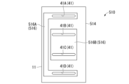
- a header 510 has an intermediate plate 514 having a plurality of spatial flow passages 516 (516A, 516B).
- the spatial flow path 516A includes the uppermost through hole 41A and the fourth through hole 41D from the top. Therefore, the spatial flow path 516A connects the refrigerant flow path 34 of the heat exchange tube 30 inserted into the through hole 41A with the refrigerant flow path 34 of the heat exchange tube 30 inserted into the through hole 41D.
- the spatial flow path 516B includes the second through hole 41B from the top and the third through hole 41C from the top. Therefore, the spatial flow path 516B connects the refrigerant flow path 34 of the heat exchange tube 30 inserted into the through hole 41B with the refrigerant flow path 34 of the heat exchange tube 30 inserted into the through hole 41C.
- the degree of freedom in the flow path configuration can be increased by using a spatial flow path 516 that includes a plurality of through holes 41 that are spaced apart from each other.
- the header 510 can be used as a first header and/or a second header.
- FIG. 9 is a schematic diagram of a third modified example of the header. Components common to the other embodiments are given the same reference numerals and will not be described. As shown in Figure 9, in the header 610, it is preferable that at least a portion of the opening 51a (outlet) of the first refrigerant port 51 connected to the first through hole 42 leading to the spatial flow path 16A is located lower than the opening 34a of the refrigerant flow path 34 of the heat exchange tube 30 inserted into the through hole 41.
- the header 610 can be used as a first header and/or a second header.
- 10 is a schematic diagram of a fourth modified example of the header. Components common to the other embodiments are given the same reference numerals and will not be described.
- the first through hole 42 and the second through hole 43 are formed at different positions in the Y direction.
- the first through hole 42 and the second through hole 43 are positioned at different positions in the left-right direction.
- the first refrigerant port connected to the first through hole 42 and the second refrigerant port connected to the second through hole 43 can be arranged with their positions shifted in the Y direction (the width direction of the heat exchange tube 30).
- the header 710 can be used as a first header and/or a second header.
- the number of spatial flow paths formed in the head is not particularly limited.
- the number of spatial flow paths can be one or more (any number greater than or equal to two).
- the number of intermediate plates is one, but the number of intermediate plates is not particularly limited.
- the number of intermediate plates can be one or more.
- the first header 10 and the second header 20 have a structure in which one intermediate plate and two end plates are stacked, but the number of end plates may be one.
- the refrigerant inlet and outlet are formed only in the first outer end plate, but the refrigerant inlet and outlet may be formed in the second outer end plate.
- the refrigerant inlet and outlet can be formed in either the first outer end plate or the second outer end plate.
- the refrigerant is divided into multiple parts and each part is circulated through a composite flow path, thereby improving the efficiency of heat exchange.
- 1...refrigeration cycle device 4, 204, 304...heat exchanger, 10...first header, 11...first inner end plate, 14...first intermediate plate, 16...spatial flow path (first spatial flow path), 17...first outer end plate, 20...second header, 21...second inner end plate, 24...second intermediate plate, 26...spatial flow path (second spatial flow path), 27...second outer end plate, 30...heat exchange tube (heat transfer tube), 34...refrigerant flow path, 34a...opening, 40...combined flow path, 51a...opening (outlet), 121...collecting flow path.
Landscapes
- Engineering & Computer Science (AREA)
- Physics & Mathematics (AREA)
- Thermal Sciences (AREA)
- Mechanical Engineering (AREA)
- General Engineering & Computer Science (AREA)
- Heat-Exchange Devices With Radiators And Conduit Assemblies (AREA)
Priority Applications (3)
| Application Number | Priority Date | Filing Date | Title |
|---|---|---|---|
| JP2024509321A JP7716575B2 (ja) | 2023-01-18 | 2023-01-18 | 熱交換器および冷凍サイクル装置 |
| CN202380073293.3A CN120077242A (zh) | 2023-01-18 | 2023-01-18 | 热交换器及冷冻循环装置 |
| PCT/JP2023/001310 WO2024154246A1 (ja) | 2023-01-18 | 2023-01-18 | 熱交換器および冷凍サイクル装置 |
Applications Claiming Priority (1)
| Application Number | Priority Date | Filing Date | Title |
|---|---|---|---|
| PCT/JP2023/001310 WO2024154246A1 (ja) | 2023-01-18 | 2023-01-18 | 熱交換器および冷凍サイクル装置 |
Publications (1)
| Publication Number | Publication Date |
|---|---|
| WO2024154246A1 true WO2024154246A1 (ja) | 2024-07-25 |
Family
ID=91955590
Family Applications (1)
| Application Number | Title | Priority Date | Filing Date |
|---|---|---|---|
| PCT/JP2023/001310 Ceased WO2024154246A1 (ja) | 2023-01-18 | 2023-01-18 | 熱交換器および冷凍サイクル装置 |
Country Status (3)
| Country | Link |
|---|---|
| JP (1) | JP7716575B2 (https=) |
| CN (1) | CN120077242A (https=) |
| WO (1) | WO2024154246A1 (https=) |
Cited By (1)
| Publication number | Priority date | Publication date | Assignee | Title |
|---|---|---|---|---|
| JP7719410B1 (ja) * | 2024-09-30 | 2025-08-06 | ダイキン工業株式会社 | 熱交換器ユニット、空調室内機、及び冷凍サイクル装置 |
Citations (4)
| Publication number | Priority date | Publication date | Assignee | Title |
|---|---|---|---|---|
| JP2009270781A (ja) * | 2008-05-08 | 2009-11-19 | Mitsubishi Electric Corp | 熱交換器モジュール、熱交換器、室内ユニット及び空調冷凍装置 |
| WO2021130834A1 (ja) * | 2019-12-24 | 2021-07-01 | 東芝キヤリア株式会社 | 熱交換器および冷凍サイクル装置 |
| WO2021130835A1 (ja) * | 2019-12-24 | 2021-07-01 | 東芝キヤリア株式会社 | 熱交換器および冷凍サイクル装置 |
| WO2022244188A1 (ja) * | 2021-05-20 | 2022-11-24 | 三菱電機株式会社 | 空気調和装置の室内ユニット |
Family Cites Families (6)
| Publication number | Priority date | Publication date | Assignee | Title |
|---|---|---|---|---|
| US9976820B2 (en) | 2013-05-15 | 2018-05-22 | Mitsubishi Electric Corporation | Stacking-type header, heat exchanger, and air-conditioning apparatus |
| DE102014203038A1 (de) | 2014-02-19 | 2015-08-20 | MAHLE Behr GmbH & Co. KG | Wärmeübertrager |
| JP6466047B1 (ja) | 2018-08-22 | 2019-02-06 | 三菱電機株式会社 | 熱交換器及び空気調和装置 |
| ES2975262T3 (es) | 2020-01-23 | 2024-07-04 | Mitsubishi Electric Corp | Intercambiador de calor y aparato de ciclo de refrigeración |
| JP7498133B2 (ja) | 2021-03-25 | 2024-06-11 | 日本キヤリア株式会社 | 熱交換器および冷凍サイクル装置 |
| CN117321373A (zh) | 2021-05-18 | 2023-12-29 | 东芝开利株式会社 | 热交换器以及制冷循环装置 |
-
2023
- 2023-01-18 JP JP2024509321A patent/JP7716575B2/ja active Active
- 2023-01-18 CN CN202380073293.3A patent/CN120077242A/zh active Pending
- 2023-01-18 WO PCT/JP2023/001310 patent/WO2024154246A1/ja not_active Ceased
Patent Citations (4)
| Publication number | Priority date | Publication date | Assignee | Title |
|---|---|---|---|---|
| JP2009270781A (ja) * | 2008-05-08 | 2009-11-19 | Mitsubishi Electric Corp | 熱交換器モジュール、熱交換器、室内ユニット及び空調冷凍装置 |
| WO2021130834A1 (ja) * | 2019-12-24 | 2021-07-01 | 東芝キヤリア株式会社 | 熱交換器および冷凍サイクル装置 |
| WO2021130835A1 (ja) * | 2019-12-24 | 2021-07-01 | 東芝キヤリア株式会社 | 熱交換器および冷凍サイクル装置 |
| WO2022244188A1 (ja) * | 2021-05-20 | 2022-11-24 | 三菱電機株式会社 | 空気調和装置の室内ユニット |
Cited By (2)
| Publication number | Priority date | Publication date | Assignee | Title |
|---|---|---|---|---|
| JP7719410B1 (ja) * | 2024-09-30 | 2025-08-06 | ダイキン工業株式会社 | 熱交換器ユニット、空調室内機、及び冷凍サイクル装置 |
| WO2026069792A1 (ja) * | 2024-09-30 | 2026-04-02 | ダイキン工業株式会社 | 熱交換器ユニット、空調室内機、及び冷凍サイクル装置 |
Also Published As
| Publication number | Publication date |
|---|---|
| JPWO2024154246A1 (https=) | 2024-07-25 |
| JP7716575B2 (ja) | 2025-07-31 |
| CN120077242A (zh) | 2025-05-30 |
Similar Documents
| Publication | Publication Date | Title |
|---|---|---|
| CN107208983B (zh) | 板式热交换器以及热泵式室外机 | |
| CN103348212B (zh) | 热交换器及空调装置 | |
| JP7590519B2 (ja) | 熱交換器および冷凍サイクル装置 | |
| US10041710B2 (en) | Heat exchanger and air conditioner | |
| US20110056667A1 (en) | Integrated multi-circuit microchannel heat exchanger | |
| EP2242963A1 (en) | Heat exchanger including multiple tube distributor | |
| KR20170031556A (ko) | 마이크로 채널 타입 열교환기 | |
| CN113587251A (zh) | 空调器 | |
| CN113587250A (zh) | 空调器 | |
| JP7716575B2 (ja) | 熱交換器および冷凍サイクル装置 | |
| JP2003269822A (ja) | 熱交換器および冷凍サイクル | |
| CN110285603A (zh) | 热交换器和使用其的制冷系统 | |
| JPH0355490A (ja) | 熱交換器 | |
| JP6939869B2 (ja) | 熱交換器 | |
| JP2024045455A (ja) | 熱交換器および冷凍サイクル装置 | |
| WO2025062640A1 (ja) | 熱交換器および冷凍サイクル装置 | |
| JP2022148994A (ja) | 熱交換器および冷凍サイクル装置 | |
| JP2025045994A (ja) | 熱交換器および冷凍サイクル装置 | |
| JP2025183039A (ja) | 熱交換器および冷凍サイクル装置 | |
| JPWO2021117107A1 (ja) | 分配装置、分配装置を備えた熱交換器およびその熱交換器を備えた空気調和機 | |
| JP7456099B2 (ja) | 熱交換器 | |
| KR20240041109A (ko) | 열교환기 | |
| WO2024241381A1 (ja) | 熱交換器および冷凍サイクル装置 | |
| WO2025062643A1 (ja) | 熱交換器 | |
| KR20240129301A (ko) | 열교환기 |
Legal Events
| Date | Code | Title | Description |
|---|---|---|---|
| WWE | Wipo information: entry into national phase |
Ref document number: 2024509321 Country of ref document: JP |
|
| 121 | Ep: the epo has been informed by wipo that ep was designated in this application |
Ref document number: 23917460 Country of ref document: EP Kind code of ref document: A1 |
|
| WWE | Wipo information: entry into national phase |
Ref document number: 202380073293.3 Country of ref document: CN |
|
| WWP | Wipo information: published in national office |
Ref document number: 202380073293.3 Country of ref document: CN |
|
| NENP | Non-entry into the national phase |
Ref country code: DE |
|
| 122 | Ep: pct application non-entry in european phase |
Ref document number: 23917460 Country of ref document: EP Kind code of ref document: A1 |