WO2024154181A1 - 液化水素設備 - Google Patents
液化水素設備 Download PDFInfo
- Publication number
- WO2024154181A1 WO2024154181A1 PCT/JP2023/000954 JP2023000954W WO2024154181A1 WO 2024154181 A1 WO2024154181 A1 WO 2024154181A1 JP 2023000954 W JP2023000954 W JP 2023000954W WO 2024154181 A1 WO2024154181 A1 WO 2024154181A1
- Authority
- WO
- WIPO (PCT)
- Prior art keywords
- gas
- pipe
- liquefied hydrogen
- liquid
- piping
- Prior art date
- Legal status (The legal status is an assumption and is not a legal conclusion. Google has not performed a legal analysis and makes no representation as to the accuracy of the status listed.)
- Ceased
Links
Images

Classifications
-
- F—MECHANICAL ENGINEERING; LIGHTING; HEATING; WEAPONS; BLASTING
- F17—STORING OR DISTRIBUTING GASES OR LIQUIDS
- F17C—VESSELS FOR CONTAINING OR STORING COMPRESSED, LIQUEFIED OR SOLIDIFIED GASES; FIXED-CAPACITY GAS-HOLDERS; FILLING VESSELS WITH, OR DISCHARGING FROM VESSELS, COMPRESSED, LIQUEFIED, OR SOLIDIFIED GASES
- F17C13/00—Details of vessels or of the filling or discharging of vessels
- F17C13/04—Arrangement or mounting of valves
-
- B—PERFORMING OPERATIONS; TRANSPORTING
- B63—SHIPS OR OTHER WATERBORNE VESSELS; RELATED EQUIPMENT
- B63B—SHIPS OR OTHER WATERBORNE VESSELS; EQUIPMENT FOR SHIPPING
- B63B27/00—Arrangement of ship-based loading or unloading equipment for cargo or passengers
- B63B27/24—Arrangement of ship-based loading or unloading equipment for cargo or passengers of pipe-lines
-
- F—MECHANICAL ENGINEERING; LIGHTING; HEATING; WEAPONS; BLASTING
- F17—STORING OR DISTRIBUTING GASES OR LIQUIDS
- F17C—VESSELS FOR CONTAINING OR STORING COMPRESSED, LIQUEFIED OR SOLIDIFIED GASES; FIXED-CAPACITY GAS-HOLDERS; FILLING VESSELS WITH, OR DISCHARGING FROM VESSELS, COMPRESSED, LIQUEFIED, OR SOLIDIFIED GASES
- F17C13/00—Details of vessels or of the filling or discharging of vessels
- F17C13/004—Details of vessels or of the filling or discharging of vessels for large storage vessels not under pressure
-
- F—MECHANICAL ENGINEERING; LIGHTING; HEATING; WEAPONS; BLASTING
- F17—STORING OR DISTRIBUTING GASES OR LIQUIDS
- F17C—VESSELS FOR CONTAINING OR STORING COMPRESSED, LIQUEFIED OR SOLIDIFIED GASES; FIXED-CAPACITY GAS-HOLDERS; FILLING VESSELS WITH, OR DISCHARGING FROM VESSELS, COMPRESSED, LIQUEFIED, OR SOLIDIFIED GASES
- F17C13/00—Details of vessels or of the filling or discharging of vessels
- F17C13/12—Arrangements or mounting of devices for preventing or minimising the effect of explosion ; Other safety measures
-
- F—MECHANICAL ENGINEERING; LIGHTING; HEATING; WEAPONS; BLASTING
- F17—STORING OR DISTRIBUTING GASES OR LIQUIDS
- F17C—VESSELS FOR CONTAINING OR STORING COMPRESSED, LIQUEFIED OR SOLIDIFIED GASES; FIXED-CAPACITY GAS-HOLDERS; FILLING VESSELS WITH, OR DISCHARGING FROM VESSELS, COMPRESSED, LIQUEFIED, OR SOLIDIFIED GASES
- F17C9/00—Methods or apparatus for discharging liquefied or solidified gases from vessels not under pressure
-
- F—MECHANICAL ENGINEERING; LIGHTING; HEATING; WEAPONS; BLASTING
- F17—STORING OR DISTRIBUTING GASES OR LIQUIDS
- F17C—VESSELS FOR CONTAINING OR STORING COMPRESSED, LIQUEFIED OR SOLIDIFIED GASES; FIXED-CAPACITY GAS-HOLDERS; FILLING VESSELS WITH, OR DISCHARGING FROM VESSELS, COMPRESSED, LIQUEFIED, OR SOLIDIFIED GASES
- F17C2205/00—Vessel construction, in particular mounting arrangements, attachments or identifications means
- F17C2205/03—Fluid connections, filters, valves, closure means or other attachments
- F17C2205/0302—Fittings, valves, filters, or components in connection with the gas storage device
- F17C2205/0323—Valves
- F17C2205/0332—Safety valves or pressure relief valves
-
- F—MECHANICAL ENGINEERING; LIGHTING; HEATING; WEAPONS; BLASTING
- F17—STORING OR DISTRIBUTING GASES OR LIQUIDS
- F17C—VESSELS FOR CONTAINING OR STORING COMPRESSED, LIQUEFIED OR SOLIDIFIED GASES; FIXED-CAPACITY GAS-HOLDERS; FILLING VESSELS WITH, OR DISCHARGING FROM VESSELS, COMPRESSED, LIQUEFIED, OR SOLIDIFIED GASES
- F17C2221/00—Handled fluid, in particular type of fluid
- F17C2221/01—Pure fluids
- F17C2221/012—Hydrogen
-
- F—MECHANICAL ENGINEERING; LIGHTING; HEATING; WEAPONS; BLASTING
- F17—STORING OR DISTRIBUTING GASES OR LIQUIDS
- F17C—VESSELS FOR CONTAINING OR STORING COMPRESSED, LIQUEFIED OR SOLIDIFIED GASES; FIXED-CAPACITY GAS-HOLDERS; FILLING VESSELS WITH, OR DISCHARGING FROM VESSELS, COMPRESSED, LIQUEFIED, OR SOLIDIFIED GASES
- F17C2223/00—Handled fluid before transfer, i.e. state of fluid when stored in the vessel or before transfer from the vessel
- F17C2223/01—Handled fluid before transfer, i.e. state of fluid when stored in the vessel or before transfer from the vessel characterised by the phase
- F17C2223/0146—Two-phase
- F17C2223/0153—Liquefied gas, e.g. LPG, GPL
-
- Y—GENERAL TAGGING OF NEW TECHNOLOGICAL DEVELOPMENTS; GENERAL TAGGING OF CROSS-SECTIONAL TECHNOLOGIES SPANNING OVER SEVERAL SECTIONS OF THE IPC; TECHNICAL SUBJECTS COVERED BY FORMER USPC CROSS-REFERENCE ART COLLECTIONS [XRACs] AND DIGESTS
- Y02—TECHNOLOGIES OR APPLICATIONS FOR MITIGATION OR ADAPTATION AGAINST CLIMATE CHANGE
- Y02E—REDUCTION OF GREENHOUSE GAS [GHG] EMISSIONS, RELATED TO ENERGY GENERATION, TRANSMISSION OR DISTRIBUTION
- Y02E60/00—Enabling technologies; Technologies with a potential or indirect contribution to GHG emissions mitigation
- Y02E60/30—Hydrogen technology
- Y02E60/32—Hydrogen storage
Definitions
- This disclosure relates to liquefied hydrogen facilities.
- Patent Document 1 discloses a portable loading and unloading facility for liquid hydrogen to transfer liquid hydrogen between a ship-side cryogenic tank and a land-side cryogenic tank.
- the present disclosure therefore aims to provide liquefied hydrogen equipment that can prevent damage to gas piping connected to a liquefied hydrogen tank.
- the liquefied hydrogen equipment includes a liquefied hydrogen tank for storing liquefied hydrogen, a gas pipe connected to the liquefied hydrogen tank for transporting hydrogen gas, and a gas-side relief pipe whose inlet is connected to the gas pipe and includes a pressure relief valve that opens when the pressure on the inlet side reaches a set pressure.
- the above configuration makes it possible to prevent damage to the gas piping connected to the liquefied hydrogen tank.
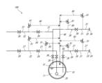
- FIG. 1 is a schematic diagram of a liquefied hydrogen facility according to a first embodiment.
- FIG. 2 is a schematic diagram of a liquefied hydrogen facility according to the second embodiment.
- FIG. 1 is a schematic diagram of the liquefied hydrogen facility 100 according to the first embodiment.
- the liquefied hydrogen facility 100 is a facility that handles liquefied hydrogen, and may be located on land or on a ship.
- the liquefied hydrogen equipment 100 includes a liquefied hydrogen tank 10, a liquid pipe 20, a gas pipe 30, a common return pipe 40, a liquid side relief pipe 50, and a gas side relief pipe 60. Below, these components will be described in order.
- the liquefied hydrogen tank 10 is a tank that stores liquefied hydrogen.
- the liquefied hydrogen tank 10 includes a liquid phase section 11 made of liquefied hydrogen, and a gas phase section 12 located above the liquid phase section 11 and made of hydrogen gas that is vaporized from the liquefied hydrogen.
- the temperature of the hydrogen gas that makes up the gas phase section 12 is close to -253°C, which is the boiling point of liquid hydrogen.
- the liquid pipe 20 is a pipe that is connected to the liquefied hydrogen tank 10 and transfers liquefied hydrogen.
- the liquid pipe 20 is shown by a solid line.
- the liquid pipe 20 includes a first liquid pipe 21 and a second liquid pipe 22.
- One end of the first liquid pipe 21 is located in the liquid phase portion 11 of the liquefied hydrogen tank 10, and the other end is located at a liquid pipe joint 23 that can be connected to an external facility.
- the first liquid pipe 21 can transfer liquefied hydrogen from the external facility connected to the liquid pipe joint 23 to the liquefied hydrogen tank 10, or from the liquefied hydrogen tank 10 to the external facility.
- a pump not shown is used.
- a plug 24 is attached to the liquid pipe joint 23.
- the plug 24 includes a plug that closes the end of the pipe, such as a blanking plug.
- the second liquid pipe 22 is connected to a pump 25 located in the liquid phase portion 11 of the liquefied hydrogen tank 10, and the other end is connected to equipment not shown, such as a boiler.
- the second liquid pipe 22 transports the liquefied hydrogen in the liquefied hydrogen tank 10 sucked up by the pump 25 toward equipment not shown.
- a plurality of liquid pipe valves 26 are located in the first liquid pipe 21 and the second liquid pipe 22, i.e., the liquid pipe 20.
- the liquid pipe 20 includes a plurality of liquid pipe compartments 27 that are separated by these liquid pipe valves 26 and plugs 24 closing the flow paths.
- the liquid pipe compartments 27 do not have to have all ends separated by the liquid pipe valves 26, and may be compartments in which at least one end is separated by the liquid pipe valve 26, for example, one end is separated by a plug 24.
- the gas pipe 30 is a pipe that is connected to the liquefied hydrogen tank 10 and transfers hydrogen gas.
- the gas pipe 30 is shown by a dashed line.
- the gas pipe 30 includes a first gas pipe 31 and a second gas pipe 32 connected to the first gas pipe 31.
- One end of the first gas pipe 31 is located in the gas phase portion 12 of the liquefied hydrogen tank 10, and the other end is provided with a gas pipe fitting 33 that can be connected to an external facility.
- the first gas pipe 31 can transfer hydrogen gas from an external facility connected to the gas pipe fitting 33 to the liquefied hydrogen tank 10, or from the liquefied hydrogen tank 10 to the external facility.
- a plug 34 is attached to the gas pipe fitting 33.
- the second gas pipe 32 transports the hydrogen gas in the liquefied hydrogen tank 10 that flows in through the first gas pipe 31 to equipment not shown.
- a plurality of gas pipe valves 36 are located in the first gas pipe 31 and the second gas pipe 32, i.e., the gas pipe 30.
- the gas pipe 30 includes a plurality of gas pipe compartments 37 that are separated by these gas pipe valves 36 and plugs 34 closing the flow paths.
- the gas pipe compartments 37 do not have to have all ends separated by the gas pipe valves 36, and may be compartments in which at least one end is separated by the gas pipe valve 36, for example, one end is separated by the plug 34.
- the gas pipe compartment 37 may have three or more ends, such as the gas pipe compartment 37 including the connection portion between the first gas pipe 31 and the second gas pipe 32. This is also the same as the liquid pipe compartment 27 described above.
- the common return pipe 40 is a pipe connected to the liquefied hydrogen tank 10.
- the common return pipe 40 is indicated by a two-dot chain line.
- the common return pipe 40 can transfer hydrogen gas supplied from the liquid side relief pipe 50 and the gas side relief pipe 60, which will be described later, to the liquefied hydrogen tank 10.
- One end of the common return pipe 40 is located in the gas phase section 12 of the liquefied hydrogen tank 10.
- the other end of the common return pipe 40 may be connected to the liquid side relief pipe 50, the gas side relief pipe 60, or may be closed.
- the liquefied hydrogen equipment 100 according to this embodiment is provided with one common return pipe 40. However, the liquefied hydrogen equipment 100 may be provided with multiple common return pipes 40.
- the liquid side relief pipe 50 is a pipe for reducing the internal pressure of the liquid pipe 20.
- the liquid side relief pipe 50 and the gas side relief pipe 60 described below are indicated by dashed lines.
- the liquid side relief pipe 50 of this embodiment can prevent damage to the liquid pipe 20 by moving the hydrogen gas in the liquid pipe 20 and reducing the internal pressure of the liquid pipe 20.
- the liquefied hydrogen equipment 100 is provided with a plurality of liquid side relief pipes 50.
- the liquid side relief pipes 50 according to this embodiment, hydrogen gas flows in one direction. If the upstream end of the liquid side relief pipes 50 is taken as the inlet, the inlets of the liquid side relief pipes 50 are connected to different liquid pipe sections 27. On the other hand, if the downstream end of the liquid side relief pipes 50 is taken as the outlet, the outlets of the liquid side relief pipes 50 are all connected to the common return pipe 40. In other words, the outlets of the liquid side relief pipes 50 are connected to the liquefied hydrogen tank 10 via the common return pipe 40. However, the outlets of the liquid side relief pipes 50 may be directly connected to the liquefied hydrogen tank 10. In addition, when the liquefied hydrogen equipment 100 is provided with a plurality of common return pipes 40, all or some of the outlets of the plurality of liquid side relief pipes 50 may be connected to the same common return pipe 40.
- Each liquid side relief pipe 50 includes a pressure relief valve 51.
- the pressure relief valve 51 is configured to open when the pressure on the inlet side of the pressure relief valve 51 reaches a preset pressure.
- the set pressures of the pressure relief valves 51 may be the same as or different from each other.
- the liquid side relief pipe 50 is configured as described above, for example, when the internal pressure of the corresponding liquid piping section 27 increases and the pressure on the inlet side of the pressure relief valve 51 reaches a set pressure, the pressure relief valve 51 opens. This causes the hydrogen gas in the corresponding liquid piping section 27 to be discharged to the liquefied hydrogen tank 10 via the common return pipe 40. This prevents the internal pressure of the corresponding liquid piping section 27 from increasing excessively, preventing the liquid piping 20 from being damaged.
- the gas side relief pipe 60 is a pipe for reducing the internal pressure of the gas pipe 30. Because the gas pipe 30 of this embodiment is connected to the liquefied hydrogen tank 10, the temperature of the hydrogen gas being transported is very low. Therefore, for example, if the hydrogen gas in the gas pipe 30 expands due to heat input from the outside, the internal pressure of the gas pipe 30 increases significantly, and there is a risk that the gas pipe 30 will be damaged. In such a case, the gas side relief pipe 60 of this embodiment can prevent damage to the gas pipe 30 by moving the hydrogen gas in the gas pipe 30 and reducing the internal pressure of the gas pipe 30.
- the liquefied hydrogen equipment 100 is provided with a plurality of gas side relief pipes 60.
- the hydrogen gas inside flows in one direction. If the upstream end of the gas side relief pipes 60 is the inlet, the inlets of each gas side relief pipe 60 are connected to different gas pipe sections 37. On the other hand, if the downstream end of the gas side relief pipes 60 is the outlet, the outlets of each gas side relief pipe 60 are all connected to the common return pipe 40. In other words, the outlets of each gas side relief pipe 60 are connected to the liquefied hydrogen tank 10 via the common return pipe 40. However, the outlets of each gas side relief pipe 60 may be directly connected to the liquefied hydrogen tank 10.
- the liquefied hydrogen equipment 100 when the liquefied hydrogen equipment 100 is provided with a plurality of common return pipes 40, all or some of the outlets of the plurality of gas side relief pipes 60 may be connected to the same common return pipe 40. Furthermore, even if the liquefied hydrogen facility 100 has multiple common return pipes 40, the outlet of the gas side relief pipe 60 and the outlet of the liquid side relief pipe 50 may be connected to the same common return pipe 40.
- Each gas side relief pipe 60 includes a pressure relief valve 61.
- the pressure relief valve 61 is configured to open when the pressure on the inlet side of the pressure relief valve 61 reaches a preset pressure.
- the set pressures of the pressure relief valves 61 may be the same as each other or may be different.
- the set pressure of the pressure relief valve 61 of the liquid side relief pipe 50 and the set pressure of the pressure relief valve 61 of the gas side relief pipe 60 may be the same as each other or may be different.
- the gas side relief pipe 60 is configured as described above, for example, when the internal pressure of the corresponding gas pipe section 37 increases and the pressure on the inlet side of the pressure relief valve 61 reaches a set pressure, the pressure relief valve 61 opens. This causes the hydrogen gas in the corresponding gas pipe section 37 to be discharged to the liquefied hydrogen tank 10 via the common return pipe 40. This prevents the internal pressure of the corresponding gas pipe section 37 from increasing excessively, preventing damage to the gas pipe 30.
- the liquid pipe 20 and gas pipe 30 described above are multiple pipes. Therefore, it is possible to prevent the liquid hydrogen from evaporating or the hydrogen gas from expanding within these pipes.
- FIG. 2 is a schematic diagram of the liquefied hydrogen facility 200 according to the second embodiment.
- the liquefied hydrogen facility 100 according to the first embodiment has the outlet side of the gas side relief pipe 60 connected to the liquefied hydrogen tank 10 via a common return pipe, whereas the liquefied hydrogen facility 200 according to the second embodiment differs in that the outlet side of the gas side relief pipe 60 is not connected to the liquefied hydrogen tank 10.
- both liquefied hydrogen facilities 100 and 200 have basically the same configuration.
- each gas side relief pipe 60 is connected to a gas pipe compartment 37 different from the gas pipe compartment 37 to which the inlet of that gas side relief pipe is connected.
- the inlet and outlet of each gas side relief pipe 60 are connected to different gas pipe compartments 37. Since the internal pressures of the gas pipe compartments 37 are different from each other, even with the above configuration, excessive pressure rise in each gas pipe compartment 37 is suppressed, and damage to the gas pipe 30 can be prevented.
- each gas side relief pipe 60 can be shortened, so the liquefied hydrogen equipment 200 can be simplified.
- a first item disclosed in this specification is a liquefied hydrogen facility comprising a liquefied hydrogen tank for storing liquefied hydrogen, a gas pipe connected to the liquefied hydrogen tank and for transporting hydrogen gas, and a gas side relief pipe having an inlet connected to the gas pipe and including a pressure relief valve that opens when the pressure on the inlet side reaches a set pressure.
- This configuration can prevent damage to the gas piping connected to the liquefied hydrogen tank.
- the second item disclosed in this specification is the liquefied hydrogen equipment described in the first item, in which the outlet of the gas side relief pipe is connected to the liquefied hydrogen tank.
- the third item disclosed in this specification is a liquefied hydrogen facility described in the first or second item, in which the gas piping is a multiple piping.
- This configuration makes it possible to prevent hydrogen gas from expanding inside the gas piping.
- the fourth item disclosed in this specification is a liquefied hydrogen facility described in any one of the first to third items, which includes at least one common return pipe connected to the liquefied hydrogen tank, the gas side relief pipe includes multiple gas side relief pipes, and all or some of the outlets of the multiple gas side relief pipes are connected to the liquefied hydrogen tank via the same common return pipe.
- This configuration simplifies the piping that directs hydrogen gas to the liquefied hydrogen tank.
- the fifth item disclosed in this specification is a liquefied hydrogen facility according to any one of the first to fourth items, comprising a liquid pipe connected to the liquefied hydrogen tank and transporting liquefied hydrogen, a liquid side relief pipe including a pressure relief valve whose inlet is connected to the liquid pipe and which opens when the pressure on the inlet side reaches a set pressure, and at least one common return pipe connected to the liquefied hydrogen tank, and the outlet of the gas side pressure relief valve and the outlet of the liquid side relief pipe are connected to the liquefied hydrogen tank via the same common return pipe.
- This configuration simplifies the piping that directs hydrogen gas to the liquefied hydrogen tank.
- the sixth item disclosed in this specification is a liquefied hydrogen facility described in any one of the first to third items, in which the gas piping includes a plurality of gas piping compartments, at least one end of which is separated by a gas piping valve, and the inlet and outlet of the gas side relief piping are connected to different gas piping compartments.
- This configuration allows the gas side relief piping to be shortened, simplifying the liquefied hydrogen equipment.
Landscapes
- Engineering & Computer Science (AREA)
- Mechanical Engineering (AREA)
- General Engineering & Computer Science (AREA)
- Chemical & Material Sciences (AREA)
- Combustion & Propulsion (AREA)
- Ocean & Marine Engineering (AREA)
- Filling Or Discharging Of Gas Storage Vessels (AREA)
Priority Applications (4)
| Application Number | Priority Date | Filing Date | Title |
|---|---|---|---|
| PCT/JP2023/000954 WO2024154181A1 (ja) | 2023-01-16 | 2023-01-16 | 液化水素設備 |
| CN202380089542.8A CN120435634A (zh) | 2023-01-16 | 2023-01-16 | 液化氢设备 |
| JP2024571442A JPWO2024154181A1 (https=) | 2023-01-16 | 2023-01-16 | |
| KR1020257021802A KR20250114407A (ko) | 2023-01-16 | 2023-01-16 | 액화 수소 설비 |
Applications Claiming Priority (1)
| Application Number | Priority Date | Filing Date | Title |
|---|---|---|---|
| PCT/JP2023/000954 WO2024154181A1 (ja) | 2023-01-16 | 2023-01-16 | 液化水素設備 |
Publications (1)
| Publication Number | Publication Date |
|---|---|
| WO2024154181A1 true WO2024154181A1 (ja) | 2024-07-25 |
Family
ID=91955463
Family Applications (1)
| Application Number | Title | Priority Date | Filing Date |
|---|---|---|---|
| PCT/JP2023/000954 Ceased WO2024154181A1 (ja) | 2023-01-16 | 2023-01-16 | 液化水素設備 |
Country Status (4)
| Country | Link |
|---|---|
| JP (1) | JPWO2024154181A1 (https=) |
| KR (1) | KR20250114407A (https=) |
| CN (1) | CN120435634A (https=) |
| WO (1) | WO2024154181A1 (https=) |
Cited By (1)
| Publication number | Priority date | Publication date | Assignee | Title |
|---|---|---|---|---|
| WO2026079277A1 (ja) * | 2024-10-10 | 2026-04-16 | 川崎重工業株式会社 | 燃料供給システム |
Citations (5)
| Publication number | Priority date | Publication date | Assignee | Title |
|---|---|---|---|---|
| JPH06213400A (ja) * | 1992-12-07 | 1994-08-02 | Chicago Bridge & Iron Technical Services Co | 車輌に燃料として液化天然ガスを補給する方法および装置 |
| JPH11218297A (ja) * | 1997-11-14 | 1999-08-10 | Air Prod And Chem Inc | ガス制御装置及びガス供給方法 |
| JP2004019813A (ja) * | 2002-06-18 | 2004-01-22 | Mitsubishi Heavy Ind Ltd | 低温流体用多重配管 |
| JP2011001993A (ja) * | 2009-06-17 | 2011-01-06 | Iwatani Internatl Corp | 液化水素貯蔵供給設備 |
| KR20160018630A (ko) * | 2016-01-29 | 2016-02-17 | 현대중공업 주식회사 | 액화가스 처리 시스템 |
Family Cites Families (1)
| Publication number | Priority date | Publication date | Assignee | Title |
|---|---|---|---|---|
| KR102604040B1 (ko) | 2021-01-14 | 2023-11-17 | 목포해양대학교 산학협력단 | 스마트 세척 시스템 |
-
2023
- 2023-01-16 WO PCT/JP2023/000954 patent/WO2024154181A1/ja not_active Ceased
- 2023-01-16 CN CN202380089542.8A patent/CN120435634A/zh active Pending
- 2023-01-16 JP JP2024571442A patent/JPWO2024154181A1/ja active Pending
- 2023-01-16 KR KR1020257021802A patent/KR20250114407A/ko active Pending
Patent Citations (5)
| Publication number | Priority date | Publication date | Assignee | Title |
|---|---|---|---|---|
| JPH06213400A (ja) * | 1992-12-07 | 1994-08-02 | Chicago Bridge & Iron Technical Services Co | 車輌に燃料として液化天然ガスを補給する方法および装置 |
| JPH11218297A (ja) * | 1997-11-14 | 1999-08-10 | Air Prod And Chem Inc | ガス制御装置及びガス供給方法 |
| JP2004019813A (ja) * | 2002-06-18 | 2004-01-22 | Mitsubishi Heavy Ind Ltd | 低温流体用多重配管 |
| JP2011001993A (ja) * | 2009-06-17 | 2011-01-06 | Iwatani Internatl Corp | 液化水素貯蔵供給設備 |
| KR20160018630A (ko) * | 2016-01-29 | 2016-02-17 | 현대중공업 주식회사 | 액화가스 처리 시스템 |
Cited By (1)
| Publication number | Priority date | Publication date | Assignee | Title |
|---|---|---|---|---|
| WO2026079277A1 (ja) * | 2024-10-10 | 2026-04-16 | 川崎重工業株式会社 | 燃料供給システム |
Also Published As
| Publication number | Publication date |
|---|---|
| KR20250114407A (ko) | 2025-07-29 |
| JPWO2024154181A1 (https=) | 2024-07-25 |
| CN120435634A (zh) | 2025-08-05 |
Similar Documents
| Publication | Publication Date | Title |
|---|---|---|
| KR101346235B1 (ko) | 해수 가열 장치 및 이를 이용한 액화천연가스 재기화 시스템 | |
| JP2007511717A (ja) | ボイルオフ・ガスの温度制御を行う装置と方法 | |
| CN105793640B (zh) | 用于在气体燃料系统中传递热的方法和装置 | |
| JP6994464B2 (ja) | 液化ガス貯蔵タンクの運転方法およびlngとボイルオフガスを受容するための液化ガス貯蔵タンク | |
| JP6389011B2 (ja) | 燃料タンク、特にlngタンクの弁システム | |
| WO2024154181A1 (ja) | 液化水素設備 | |
| US11613175B2 (en) | Indoor safety device, a liquefied fuel gas system and a vehicle | |
| CN116710725A (zh) | 用于高压和低压气体消耗设备的气体供应系统 | |
| US20250043917A1 (en) | Device and method for storing and supplying fluid | |
| US12422098B2 (en) | Portable cargo handling equipment for liquid hydrogen and emergency release method | |
| JP7189962B2 (ja) | ガス供給アセンブリ | |
| CN107923576B (zh) | 用于控制低温能量储存系统中的压力的系统和方法 | |
| EP3435015A1 (en) | Liquiefying a gaseous medium | |
| KR100834271B1 (ko) | Lng 저장탱크의 압력 제어 시스템 및 방법 | |
| JPWO2024154181A5 (https=) | ||
| CN115843326A (zh) | 用于装载液态天然气的系统 | |
| CN114729779A (zh) | 用于处理以液态和气态容纳在储存和/或运输气体的罐中的气体的系统 | |
| TWI918816B (zh) | 液態氫用可搬型裝卸設備及緊急脫離方法 | |
| KR101584570B1 (ko) | 해양구조물의 코퍼댐 히팅시스템 및 코퍼댐 히팅 방법 | |
| US20250305636A1 (en) | Gas supply system for high and low pressure gas consumer appliances | |
| WO2024111078A1 (ja) | 移送設備及びガス置換方法 | |
| KR101644343B1 (ko) | 순환식 기화장치 | |
| KR102608686B1 (ko) | 카고 파이핑 시스템 및 lng 로딩 방법 | |
| CN119234108A (zh) | 用于由低温液体蒸发产生的气体的储存和处理设施 | |
| WO2021181669A1 (ja) | 流体を移送するシステム及び流体の移送方法 |
Legal Events
| Date | Code | Title | Description |
|---|---|---|---|
| 121 | Ep: the epo has been informed by wipo that ep was designated in this application |
Ref document number: 23917396 Country of ref document: EP Kind code of ref document: A1 |
|
| WWE | Wipo information: entry into national phase |
Ref document number: 2024571442 Country of ref document: JP |
|
| WWE | Wipo information: entry into national phase |
Ref document number: 202380089542.8 Country of ref document: CN |
|
| WWP | Wipo information: published in national office |
Ref document number: 1020257021802 Country of ref document: KR |
|
| WWP | Wipo information: published in national office |
Ref document number: 202380089542.8 Country of ref document: CN |
|
| NENP | Non-entry into the national phase |
Ref country code: DE |
|
| 122 | Ep: pct application non-entry in european phase |
Ref document number: 23917396 Country of ref document: EP Kind code of ref document: A1 |