WO2024150792A1 - 音響信号出力装置 - Google Patents
音響信号出力装置 Download PDFInfo
- Publication number
- WO2024150792A1 WO2024150792A1 PCT/JP2024/000428 JP2024000428W WO2024150792A1 WO 2024150792 A1 WO2024150792 A1 WO 2024150792A1 JP 2024000428 W JP2024000428 W JP 2024000428W WO 2024150792 A1 WO2024150792 A1 WO 2024150792A1
- Authority
- WO
- WIPO (PCT)
- Prior art keywords
- acoustic signal
- driver unit
- acoustic
- output device
- signal
- Prior art date
- Legal status (The legal status is an assumption and is not a legal conclusion. Google has not performed a legal analysis and makes no representation as to the accuracy of the status listed.)
- Ceased
Links
Images





Classifications
-
- H—ELECTRICITY
- H04—ELECTRIC COMMUNICATION TECHNIQUE
- H04R—LOUDSPEAKERS, MICROPHONES, GRAMOPHONE PICK-UPS OR LIKE ACOUSTIC ELECTROMECHANICAL TRANSDUCERS; ELECTRIC HEARING AIDS; PUBLIC ADDRESS SYSTEMS
- H04R1/00—Details of transducers, loudspeakers or microphones
- H04R1/20—Arrangements for obtaining desired frequency or directional characteristics
- H04R1/32—Arrangements for obtaining desired frequency or directional characteristics for obtaining desired directional characteristic only
- H04R1/40—Arrangements for obtaining desired frequency or directional characteristics for obtaining desired directional characteristic only by combining a number of identical transducers
- H04R1/403—Arrangements for obtaining desired frequency or directional characteristics for obtaining desired directional characteristic only by combining a number of identical transducers loud-speakers
-
- H—ELECTRICITY
- H04—ELECTRIC COMMUNICATION TECHNIQUE
- H04R—LOUDSPEAKERS, MICROPHONES, GRAMOPHONE PICK-UPS OR LIKE ACOUSTIC ELECTROMECHANICAL TRANSDUCERS; ELECTRIC HEARING AIDS; PUBLIC ADDRESS SYSTEMS
- H04R1/00—Details of transducers, loudspeakers or microphones
- H04R1/10—Earpieces; Attachments therefor ; Earphones; Monophonic headphones
-
- H—ELECTRICITY
- H04—ELECTRIC COMMUNICATION TECHNIQUE
- H04R—LOUDSPEAKERS, MICROPHONES, GRAMOPHONE PICK-UPS OR LIKE ACOUSTIC ELECTROMECHANICAL TRANSDUCERS; ELECTRIC HEARING AIDS; PUBLIC ADDRESS SYSTEMS
- H04R1/00—Details of transducers, loudspeakers or microphones
- H04R1/20—Arrangements for obtaining desired frequency or directional characteristics
- H04R1/32—Arrangements for obtaining desired frequency or directional characteristics for obtaining desired directional characteristic only
- H04R1/34—Arrangements for obtaining desired frequency or directional characteristics for obtaining desired directional characteristic only by using a single transducer with sound reflecting, diffracting, directing or guiding means
- H04R1/345—Arrangements for obtaining desired frequency or directional characteristics for obtaining desired directional characteristic only by using a single transducer with sound reflecting, diffracting, directing or guiding means for loudspeakers
-
- H—ELECTRICITY
- H04—ELECTRIC COMMUNICATION TECHNIQUE
- H04R—LOUDSPEAKERS, MICROPHONES, GRAMOPHONE PICK-UPS OR LIKE ACOUSTIC ELECTROMECHANICAL TRANSDUCERS; ELECTRIC HEARING AIDS; PUBLIC ADDRESS SYSTEMS
- H04R1/00—Details of transducers, loudspeakers or microphones
- H04R1/20—Arrangements for obtaining desired frequency or directional characteristics
- H04R1/32—Arrangements for obtaining desired frequency or directional characteristics for obtaining desired directional characteristic only
- H04R1/40—Arrangements for obtaining desired frequency or directional characteristics for obtaining desired directional characteristic only by combining a number of identical transducers
-
- H—ELECTRICITY
- H04—ELECTRIC COMMUNICATION TECHNIQUE
- H04R—LOUDSPEAKERS, MICROPHONES, GRAMOPHONE PICK-UPS OR LIKE ACOUSTIC ELECTROMECHANICAL TRANSDUCERS; ELECTRIC HEARING AIDS; PUBLIC ADDRESS SYSTEMS
- H04R3/00—Circuits for transducers
- H04R3/12—Circuits for transducers for distributing signals to two or more loudspeakers
Definitions
- the present invention relates to an audio signal output device, and in particular to an audio signal output device that does not seal the ear canal.
- open-ear earphones and headphones have the problem of significant sound leakage to the surroundings. This problem is not limited to open-ear earphones and headphones, but is a common problem with audio signal output devices that do not seal the ear canal, including installed speakers and built-in speakers.
- the present invention was made in consideration of these points, and aims to provide an acoustic signal output device that does not seal the ear canal and can suppress sound leakage to the surroundings.
- An audio signal output device has a single or multiple first driver units that emit a first audio signal in a first direction, and a single or multiple second driver units that emit a second audio signal in the first direction.
- the first driver unit and the second driver unit are arranged along the same imaginary plane, and the second driver unit is arranged in a ring shape around the first driver unit.
- the attenuation rate of the first audio signal at a second point farther from the audio signal output device than the first point based on a predetermined first point where the first audio signal arrives is designed to be equal to or less than a predetermined value that is smaller than the attenuation rate of the audio signal due to air propagation at the second point based on the first point.
- the attenuation amount of the first audio signal at the second point based on the first point is designed to be equal to or greater than a predetermined value that is larger than the attenuation amount of the audio signal due to air propagation at the second point based on the first point.
- This structure helps prevent sound from leaking into the surrounding area.
- FIG. 1 is a see-through perspective view illustrating the configuration of an acoustic signal output device according to a first embodiment.
- 2A and 2B are transparent plan and front views illustrating the configuration of the acoustic signal output device of the first embodiment.
- FIG. 3 is a diagram for explaining the supply of an electric signal to the acoustic signal output device of the first embodiment.
- Fig. 4A is a diagram illustrating a state of use of the acoustic signal output device of the first embodiment
- Fig. 4B is a diagram illustrating a state of an acoustic signal emitted from the acoustic signal output device of the first embodiment.
- Fig. 1 is a see-through perspective view illustrating the configuration of an acoustic signal output device according to a first embodiment.
- 2A and 2B are transparent plan and front views illustrating the configuration of the acoustic signal output device of the first embodiment.
- FIG. 3 is a diagram for explaining the supply of an electric signal
- FIG. 5A is a diagram for illustrating a numerical analysis model in the case where a plurality of sound emitting surfaces that emit sound signals are not on the same plane
- Fig. 5B is an enlarged view of a region R1 in Fig. 5A
- FIG. 6 is a diagram illustrating a numerical analysis model of acoustic radiation when a plurality of sound emitting surfaces that emit acoustic signals are not on the same plane
- Fig. 7A is a diagram illustrating a numerical analysis model in which a plurality of sound emitting surfaces that emit acoustic signals are on the same plane, and other sound emitting surfaces are arranged coaxially and annularly around a certain sound emitting surface.
- FIG. 7B is an enlarged view of a region R1 in Fig. 7A.
- FIG. 8 is a diagram illustrating a numerical analysis model of acoustic radiation when multiple acoustic emitting surfaces that emit acoustic signals are on the same plane and other acoustic emitting surfaces are arranged coaxially and annularly around one acoustic emitting surface.
- Fig. 9A is a diagram for illustrating a numerical analysis model in the case where a plurality of sound emitting surfaces that emit acoustic signals are not on the same plane, and Fig.
- FIG. 9B is a diagram for illustrating a numerical analysis model in the case where a plurality of sound emitting surfaces that emit acoustic signals are on the same plane and other sound emitting surfaces are arranged coaxially and annularly around one sound emitting surface.
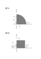
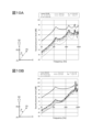
- 10A is a graph illustrating acoustic characteristics when multiple sound emitting surfaces that emit acoustic signals are not on the same plane
- FIG. 10B is a graph illustrating acoustic characteristics when multiple sound emitting surfaces that emit acoustic signals are on the same plane and the other sound emitting surfaces are arranged coaxially and annularly around one sound emitting surface.
- 11A and 11B are transparent plan views illustrating the configuration of an acoustic signal output device according to the second embodiment.
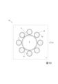
- FIG. 12 is a transparent plan view illustrating the configuration of an acoustic signal output device according to the third embodiment.
- the acoustic signal output device 10 of this embodiment is a device for listening to sound that is worn without sealing the user's ear canal (for example, open-ear type earphones, headphones, installed speakers, embedded speakers, etc.). As illustrated in Figs.
- the acoustic signal output device 10 of this embodiment has a driver unit 11 (first driver unit) that converts an output signal (electrical signal representing an acoustic signal) OUT1 output from the signal processing device 100 into an acoustic signal AC1 (first acoustic signal) and emits this acoustic signal AC1 in a direction D1 (first direction), and a driver unit 12 (second driver unit) that converts an output signal OUT2 output from the signal processing device 100 into an acoustic signal AC2 (second acoustic signal) and emits this acoustic signal AC2 in the D1 direction (first direction).
- first driver unit that converts an output signal (electrical signal representing an acoustic signal) OUT1 output from the signal processing device 100 into an acoustic signal AC1 (first acoustic signal) and emits this acoustic signal AC1 in a direction D1 (first direction)
- a driver unit 12 second driver unit
- the driver unit 11 and the driver unit 12 are arranged along the same virtual plane P, and the driver unit 12 is arranged in a ring shape around the driver unit 11.
- the attenuation rate of the acoustic signal AC1 at a position P2 (second position) farther from the acoustic signal output device 10 than a position P1 (first position) based on a predetermined position P1 where the acoustic signal AC1 reaches is designed to be equal to or less than a predetermined value that is smaller than the attenuation rate of the acoustic signal due to air propagation at the position P2 based on the position P1.
- the attenuation amount of the acoustic signal AC1 at the position P2 based on the position P1 is designed to be equal to or greater than a predetermined value that is larger than the attenuation amount of the acoustic signal due to air propagation at the position P2 based on the position P1. This will be described in detail below.
- the driver unit (speaker driver unit) 11 is a device (device having a speaker function) that emits (emits sound) an acoustic signal AC1 (first acoustic signal) based on the input output signal OUT1 to one side (D1 direction side) and emits an acoustic signal AC3 (third acoustic signal) that is an inverse phase signal (phase inversion signal) of the acoustic signal AC1 or an approximation signal of the inverse phase signal to the other side (D2 direction side).
- the driver unit 11 includes a diaphragm 113 that emits the acoustic signal AC1 from one surface 113a in the D1 direction by vibration and emits the acoustic signal AC3 from the other surface 113b in the D2 direction by this vibration (FIG. 2B).
- the driver unit 11 emits the acoustic signal AC1 from one side surface 111 in the D1 direction by vibrating the diaphragm 113 based on the input output signal OUT1, and emits the acoustic signal AC3, which is an inverse phase signal or an approximation of the inverse phase signal of the acoustic signal AC1, from the other side 112 in the D2 direction. That is, the acoustic signal AC3 is emitted secondarily with the emission of the acoustic signal AC1.
- the D2 direction (the other side) is, for example, the inverse or approximately inverse direction of the D1 direction (one side), but the D2 direction does not need to be strictly the inverse or approximately inverse direction of the D1 direction, as long as the D2 direction is different from the D1 direction.
- the acoustic signal AC3 may be strictly an inverse phase signal of the acoustic signal AC1, or the acoustic signal AC3 may be an approximation of the inverse phase signal of the acoustic signal AC1.
- the approximation signal of the opposite phase signal of the acoustic signal AC1 may be (1) a signal obtained by shifting the phase of the opposite phase signal of the acoustic signal AC1, (2) a signal obtained by changing (amplifying or attenuating) the amplitude of the opposite phase signal of the acoustic signal AC1, or (3) a signal obtained by shifting the phase of the opposite phase signal of the acoustic signal AC1 and further changing the amplitude.
- the phase difference between the opposite phase signal of the acoustic signal AC1 and its approximation signal is desirably ⁇ 1 % or less of one period of the opposite phase signal of the acoustic signal AC1.
- ⁇ 1 % are 1%, 3%, 5%, 10%, 20%, etc.
- the difference between the amplitude of the opposite phase signal of the acoustic signal AC1 and the amplitude of its approximation signal is desirably ⁇ 2 % or less of the amplitude of the opposite phase signal of the acoustic signal AC1.
- Examples of ⁇ 2 % are 1%, 3%, 5%, 10%, 20%, etc.
- examples of the type of the driver unit 11 include a dynamic type, a balanced armature chair type, a hybrid type of a dynamic type and a balanced armature type, and a condenser type.
- the shape of the driver unit 11 and the diaphragm 113 there is no limitation on the shape of the driver unit 11 and the diaphragm 113.
- the outer shape of the driver unit 11 is a substantially cylindrical shape with both end faces and the diaphragm 113 is a substantially disc shape, but this does not limit the present invention.
- the outer shape of the driver unit 11 may be a rectangular parallelepiped shape, and the diaphragm 113 may be a dome shape.
- examples of the acoustic signal include music, voice, sound effects, environmental sounds, and other sounds.
- the driver unit (speaker driver unit) 12 is arranged in a ring shape around the driver unit 11, and is a device (device with speaker function) that emits (emits sound) an acoustic signal AC2 (second acoustic signal) based on the input output signal OUT2 to one side (D1 direction side), and emits an acoustic signal AC4 (fourth acoustic signal) that is an inverse phase signal (phase inversion signal) of the acoustic signal AC2 or an approximation signal of the inverse phase signal to the other side (D2 direction side).
- the driver unit 12 includes a diaphragm 123 that emits the acoustic signal AC2 from one surface 123a in the D1 direction by vibration, and emits the acoustic signal AC4 from the other surface 123b in the D2 direction by this vibration (FIG. 2B).
- the driver unit 12 emits the acoustic signal AC2 from one side 121 in the direction D1 by vibrating the diaphragm 123 based on the input output signal OUT2, and emits the acoustic signal AC4, which is an inverse phase signal of the acoustic signal AC2 or an approximation signal of the inverse phase signal, from the other side 122 in the direction D2. That is, the acoustic signal AC4 is emitted secondarily in association with the emission of the acoustic signal AC2.
- the acoustic signal AC4 may be a signal that is strictly an inverse phase signal of the acoustic signal AC2, or may be an approximation signal of the inverse phase signal of the acoustic signal AC2.
- the approximation signal of the inverse phase signal of the acoustic signal AC2 may be (1) a signal obtained by shifting the phase of the inverse phase signal of the acoustic signal AC2, (2) a signal obtained by changing (amplifying or attenuating) the amplitude of the inverse phase signal of the acoustic signal AC2, or (3) a signal obtained by shifting the phase of the inverse phase signal of the acoustic signal AC2 and further changing the amplitude.
- the phase difference between the antiphase signal of the acoustic signal AC2 and its approximation signal is desirably ⁇ 1 % or less of one period of the antiphase signal of the acoustic signal AC2.
- ⁇ 1 % are 1%, 3%, 5%, 10%, 20%, etc.
- the difference between the amplitude of the antiphase signal of the acoustic signal AC2 and the amplitude of its approximation signal is desirably ⁇ 2 % or less of the amplitude of the antiphase signal of the acoustic signal AC2.
- Examples of ⁇ 2 % are 1%, 3%, 5%, 10%, 20%, etc.
- the type of the driver unit 12 include a dynamic type, a balanced armature type, a hybrid type of a dynamic type and a balanced armature type, and a condenser type.
- driver unit 11 first driver unit
- driver unit 12 second driver unit
- driver unit 12 second driver unit
- driver unit 12 link-type driver unit that surrounds driver unit 11 (first driver unit).
- the shape of driver unit 12 may be any shape, such as an elliptical ring type or a rectangular frame type, as long as it can be arranged in a ring shape around driver unit 11.
- driver unit 12 (second driver unit) is arranged in a ring shape around driver unit 11 (first driver unit), and driver unit 11 and driver unit 12 are arranged along the same imaginary plane P (Figs. 1, 2A, and 2B).
- driver units 11 and 12 are arranged so that they both pass through imaginary plane P.
- Figs. 1, 2A, and 2B show an example in which diaphragm 113 of driver unit 11 and diaphragm 123 of driver unit 12 are both arranged so that they pass through imaginary plane P.
- this does not limit the present invention, and it is sufficient that driver unit 11 and driver unit 12 are arranged along imaginary plane P.
- face 111 of driver unit 11 and face 121 of driver unit 12 may be arranged so that they pass through imaginary plane P or in its vicinity, or face 112 of driver unit 11 and face 122 of driver unit 12 may be arranged so that they pass through imaginary plane P or in its vicinity.
- Virtual plane P may be a plane perpendicular to the D1 direction, a plane approximately perpendicular to the D1 direction, a plane perpendicular to the D2 direction, or a plane approximately perpendicular to the D2 direction.
- surface 111 of driver unit 11 and surface 121 of driver unit 12 do not have to be arranged on the same plane, and surface 112 of driver unit 11 and surface 122 of driver unit 12 do not have to be arranged on the same plane.
- the driver unit 12 (second driver unit) is arranged along a virtual circle C that is coaxial with the central axis A of the driver unit 11 (first driver unit) (Figs. 1 and 2A).
- the driver unit 12 may include the virtual circle C, or the driver unit 12 may be arranged in the vicinity of the virtual circle C.
- the central axis A is perpendicular or approximately perpendicular to the virtual plane P. This is expected to have a high sound leakage suppression effect.
- the central axis A does not have to be perpendicular or approximately perpendicular to the virtual plane P.
- the virtual circle C may exist on the virtual plane P, or may exist on a plane that is parallel or approximately parallel to the virtual plane P.
- the signal processing device 100 converts an input signal (electrical signal representing an acoustic signal) IN into output signals OUT1 and OUT2 and outputs them.
- the output signal OUT1 is input to the driver unit 11, which emits acoustic signals AC1 and AC3 as described above.
- the output signal OUT2 is input to the driver unit 12, which emits acoustic signals AC2 and AC4 as described above.
- the signal processing device 100 converts the input signal into output signals OUT1 and OUT2 so that the amount of sound leakage of the acoustic signals emitted from the driver units 11 and 12 is reduced at a predetermined position.
- the signal processing device 100 converts the input signal into output signals OUT1 and OUT2 so that the amount of sound leakage of the acoustic signals emitted from the driver units 11 and 12 is minimized at a predetermined position away from the user's ears.
- the signal processing device 100 converts the input signal IN so that the output signal OUT2 becomes an opposite phase signal of the output signal OUT1 or an approximation signal of the opposite phase signal of the output signal OUT1.
- the acoustic signal AC2 emitted from the driver unit 12 becomes an opposite phase signal of the acoustic signal AC1 emitted from the driver unit 11 or an approximation signal of the opposite phase signal of the acoustic signal AC1.
- the sound pressure of the acoustic signal can be minimized at multiple positions away from the user's ear by controlling the phase relationship between the acoustic signal AC1 and the acoustic signal AC2.
- the acoustic signal AC2 emitted from the driver unit 12 is an inverse phase signal or an approximation of the inverse phase signal of the acoustic signal AC1 emitted from the driver unit 11, the acoustic signals AC1 and AC2 cancel each other out far from the acoustic signal output device 10, and the sound pressure of the acoustic signal can be minimized at multiple positions away from the user's ear.
- the driver units 11 and 12 differ from each other in at least one of the shape and size. Due to this difference in shape and size, the acoustic signals AC1 and AC2 do not completely cancel each other out near the acoustic signal output device 10, and a constant sound pressure can be secured near the user's ear. As a result, the necessary sound pressure can be secured near the user's ear while suppressing sound leakage of the acoustic signal at multiple positions away from the user's ear.
- the acoustic signal output device 10 is designed so that when an acoustic signal AC1 (first acoustic signal) is emitted from the driver unit 11 (first driver unit) and an acoustic signal AC2 (second acoustic signal) is emitted from the driver unit 12 (second driver unit), the attenuation rate ⁇ 11 of the acoustic signal AC1 (first acoustic signal) at a position P2 (second point) based on the position P1 (first point) can be made equal to or less than a predetermined value ⁇ th , and the attenuation amount ⁇ 12 of the acoustic signal AC1 (first acoustic signal) at a position P2 (second point) based on the position P1 (first point) can be made equal to or more than a predetermined value ⁇ th .
- Position P1 (first point) is a predetermined point where an acoustic signal AC1 (first acoustic signal) emitted from the driver unit 11 arrives.
- Position P2 (second point) is a predetermined point farther away from the acoustic signal output device 10 than position P1 (first point).
- the predetermined value ⁇ th is a value smaller (lower) than the attenuation rate ⁇ 21 due to air propagation of an arbitrary or specific acoustic signal (sound) at position P2 (second point) based on position P1 (first point).
- the predetermined value ⁇ th is a value larger than the attenuation amount ⁇ 22 due to air propagation of an arbitrary or specific acoustic signal (sound) at position P2 (second point) based on position P1 (first point). That is, the acoustic signal output device 10 of this embodiment is designed so that the attenuation rate ⁇ 11 is equal to or smaller than a predetermined value ⁇ th smaller than the attenuation rate ⁇ 21 , or the attenuation amount ⁇ 12 is equal to or larger than a predetermined value ⁇ th larger than the attenuation amount ⁇ 22 .
- the acoustic signal AC1 is propagated through the air from position P1 to position P2, and is attenuated due to this air propagation and the acoustic signal AC2.
- the attenuation rate ⁇ 11 is the ratio (AMP2(AC1)/ AMP1 (AC1)) of the magnitude AMP2 (AC1) of the acoustic signal AC1 at position P2 attenuated due to air propagation and the acoustic signal AC2 to the magnitude AMP1 ( AC1) of the acoustic signal AC1 at position P1.
- the attenuation amount ⁇ 12 is the difference between the magnitude AMP1 (AC1) and the magnitude AMP2 (AC1) (
- any or a specific acoustic signal ACar propagating through the air from position P1 to position P2 attenuates due to air propagation and not due to the acoustic signal AC2 .
- the attenuation rate ⁇ 21 is the ratio (AMP2(ACar)/ AMP1 ( ACar )) of the magnitude AMP2 ( ACar ) of the acoustic signal ACar at position P2 attenuated due to air propagation (attenuated without being due to the acoustic signal AC2) to the magnitude AMP1 ( ACar ) of the acoustic signal ACar at position P1 .
- the attenuation amount ⁇ 22 is the difference between the magnitude AMP 1 (AC ar ) and the magnitude AMP 2 (AC ar ) (
- the magnitude of the acoustic signal include the sound pressure of the acoustic signal or the energy of the acoustic signal.
- the "sound leakage component" refers to, for example, a component of the acoustic signal AC1 emitted from the driver unit 11 that is likely to reach an area other than that of the user wearing the acoustic signal output device 10 (for example, a person other than the user wearing the acoustic signal output device 10).
- the "sound leakage component” refers to a component of the acoustic signal AC1 that propagates in a direction other than the D1 direction, or a component that propagates in the D1 direction and reaches a position other than that of the user.
- acoustic signals AC3 and AC4 are also emitted from driver units 11 and 12 in direction D2 ( Figure 3).
- acoustic signals AC1, AC2, AC3, and AC4 so as to minimize the sound pressure of the acoustic signals at multiple positions away from the user's ears, it is possible to minimize the sound pressure of the acoustic signals at multiple positions away from the user's ears.
- the acoustic signal AC2 emitted from the driver unit 12 is an opposite phase signal or an approximation of the opposite phase signal of the acoustic signal AC1 emitted from the driver unit 11
- the acoustic signal AC4 emitted from the driver unit 12 is an opposite phase signal or an approximation of the opposite phase signal of the acoustic signal AC3 emitted from the driver unit 11
- the acoustic signals AC1 and AC2 cancel each other out far from the acoustic signal output device 10
- the acoustic signals AC2 and AC4 cancel each other out so that the sound pressure of the acoustic signal can be minimized at multiple positions away from the user's ears.
- the driver units 11 and 12 are different from each other in at least one of the shape and size, they do not completely cancel each other out in the vicinity of the acoustic signal output device 10, and a constant sound pressure can be secured in the vicinity of the user's ears. As a result, it is possible to ensure the necessary sound pressure near the user's ears while suppressing sound leakage of the acoustic signal at multiple positions away from the user's ears.
- the acoustic signal output device 10 is designed so that, when acoustic signals AC1, AC3 (first acoustic signal and third acoustic signal) are emitted from the driver unit 11 (first driver unit) and acoustic signals AC2, AC4 (second acoustic signal and fourth acoustic signal) are emitted from the driver unit 12 (second driver unit), the attenuation rate ⁇ 11 of at least any of the acoustic signals AC1, AC2, AC3, AC4 (first acoustic signal to fourth acoustic signal) at position P2 (second point) based on position P1 (first point) can be made equal to or less than a predetermined value ⁇ th , and the attenuation amount ⁇ 12 of at least any of the acoustic signals AC1, AC2, AC3, AC4 (first acoustic signal to fourth acoustic signal) at position P2 based on position P1 can be made equal to or greater than a predetermined value
- acoustic signals AC1 and AC3 are emitted from the driver unit 11, and acoustic signals AC2 and AC4 are emitted from the driver unit 12, so that the attenuation rate ⁇ 11 of each of the acoustic signals AC1, AC2, AC3, and AC4 at position P2 based on position P1 can be set to a predetermined value ⁇ th or less, and the attenuation amount ⁇ 12 of each of the acoustic signals AC1, AC2, AC3, and AC4 at position P2 based on position P1 can be set to a predetermined value ⁇ th or more .
- the attenuation rate ⁇ 11 is the ratio (AMP2(ACX)/ AMP1 (ACX)) of the magnitude AMP2 (ACX) of the acoustic signal ACX at position P2 attenuated due to air propagation and the acoustic signal ACY to the magnitude AMP1 (ACX) of the acoustic signal ACX at position P1.
- the attenuation amount ⁇ 12 is the difference (
- the acoustic signal ACY is not assumed, any or a specific acoustic signal ACar propagated through the air from position P1 to position P2 is attenuated due to air propagation, not due to the acoustic signal ACY.
- the attenuation rate ⁇ 21 is the ratio (AMP2(ACar)/ AMP1 ( ACar )) of the magnitude AMP2 ( ACar ) of the acoustic signal ACar at position P2 attenuated due to air propagation (attenuation without being due to the acoustic signal ACY) to the magnitude AMP1 ( ACar ) of the acoustic signal ACar at position P1.
- the attenuation amount ⁇ 22 is the difference (
- ⁇ Usage status> 4A and 4B are used to illustrate the usage state of the acoustic signal output device 10.
- one acoustic signal output device 10 is attached to each of the right ear 1010 and the left ear 1020 of the user 1000. Any attachment mechanism is used to attach the acoustic signal output device 10 to the ear.
- the acoustic signal output device 10 is arranged near the right ear 1010 and the left ear 1020 of the user 1000 with the D1 direction side facing the user 1000.
- the driver unit 11 emits an acoustic signal AC1 in the D1 direction and emits an acoustic signal AC3 in the D2 direction.
- the driver unit 12 emits an acoustic signal AC2 in the D1 direction and emits an acoustic signal AC4 in the D2 direction.
- the sound pressure of the acoustic signals AC1 and AC2 emitted from the driver units 11 and 12 toward the D1 direction is ensured.
- sound leakage of the acoustic signals can be suppressed.
- the attenuation rate ⁇ 11 of at least one of the acoustic signals AC1, AC2, AC3, and AC4 at the position P2 based on the position P1 can be made equal to or less than a predetermined value ⁇ th
- the attenuation amount ⁇ 12 of at least one of the acoustic signals AC1, AC2, AC3, and AC4 at the position P2 based on the position P1 can be made equal to or more than a predetermined value ⁇ th .
- FIG. 4B shows an example in which the position P2 is 15 cm away from the position P1 on the outward side, this does not limit the present invention.
- acoustic signal output device 10 of the present embodiment An example of a numerical analysis showing the sound leakage suppression effect by the acoustic signal output device 10 of the present embodiment will be described.
- driver unit 12 is arranged in a ring shape around driver unit 11, and driver unit 11 and driver unit 12 are arranged along the same imaginary plane P. Furthermore, it is preferable that driver unit 12 is arranged along an imaginary circle C that is coaxial with the central axis A of driver unit 11.
- the sound leakage suppression effect when these features are provided and when they are not provided is compared by numerical analysis.
- FIG. 5A illustrates a numerical analysis model that does not have the above-mentioned features of this embodiment
- FIG. 5B illustrates an enlarged view of region R1 in FIG. 5A
- the horizontal axis H in FIG. 5A and FIG. 5B represents a perfect reflection surface that models the surface of the user's head
- the vertical axis represents an axis that models the central axis A of the acoustic signal output device.
- the space of this numerical analysis model is rotationally symmetrical about the central axis A. In the space of this example, positions P0, P1, and P2 are arranged on the central axis A.
- P0 corresponds to the installation reference position of the acoustic signal output device 10 (for example, P0 is a point on the surface of the acoustic signal output device 10), position P1 corresponds to the position of the user's ear, and P2 corresponds to a position away from position P1 to the outside of the acoustic signal output device 10.
- ⁇ 1 represents an acoustic emission surface that is centered on the central axis A and emits an acoustic signal in the D1 direction (perfect reflection surface direction, position P1 direction) along the central axis A.
- ⁇ 2 represents the sound emission surface that emits sound signals in the direction D3 parallel to the horizontal axis H perpendicular to the central axis A.
- the distance between position P1 and sound emission surface ⁇ 1 is 20 mm, and the distance between position P1 and position P2 is 15 cm.
- Figure 6 shows the results of numerical analysis in the case where the above-mentioned features of this embodiment are not included.
- Figure 6 shows the acoustic radiation state from the acoustic emission surface ⁇ 1, the acoustic radiation state from the acoustic emission surface ⁇ 2, and the superposition (mixture) of the acoustic radiation states from the acoustic emission surfaces ⁇ 1 and ⁇ 2.
- control is performed to suppress sound leakage at position P2.
- Figure 6 also shows the acoustic radiation state of a 5120 Hz acoustic signal.
- the low frequency (long wavelength) band sound leakage can be suppressed to some extent even with this configuration.
- the high frequency (short wavelength) band the spatial distribution of the waves emitted by the acoustic emission surface ⁇ 1 and the acoustic emission surface ⁇ 2 differs, making it difficult to suppress sound leakage over a wide spatial range. For example, as shown in FIG.
- FIG. 7A illustrates a numerical analysis model having the features of the present embodiment described above
- FIG. 7B illustrates an enlarged view of region R2 in FIG. 7A
- the horizontal axis H in FIG. 7A and FIG. 7B represents a perfect reflection surface modeled on the surface of the user's head
- the vertical axis represents an axis modeled on the central axis A of the acoustic signal output device.
- the space of this numerical analysis model is rotationally symmetrical about the central axis A. In this example space, positions P0, P1, and P2 are also arranged on the central axis A.
- ⁇ 11 represents an acoustic emission surface (corresponding to surface 111 of driver unit 11) that emits an acoustic signal (corresponding to acoustic signal AC1) in the D1 direction (perfect reflection surface direction, position P1 direction) centered on the central axis A.
- ⁇ 12 represents a sound emitting surface (corresponding to the surface 112 of the driver unit 11) that emits a sound signal (corresponding to the sound signal AC3) in the D2 direction (the opposite direction to the D1 direction) with the central axis A as the center.
- ⁇ 21 represents a sound emitting surface (corresponding to the surface 121 of the driver unit 12) that emits a sound signal (corresponding to the sound signal AC2) in the D1 direction (the direction of the complete reflection surface, the direction of the position P1).
- ⁇ 22 represents a sound emitting surface (corresponding to the surface 122 of the driver unit 12) that emits a sound signal (corresponding to the sound signal AC4) in the D2 direction (the opposite direction to the D1 direction).
- the sound emitting surfaces ⁇ 11, ⁇ 12, ⁇ 21, and ⁇ 22 are arranged along a virtual plane parallel to the horizontal axis H, and the sound emitting surfaces ⁇ 21 and ⁇ 22 are arranged in a ring shape around the sound emitting surfaces ⁇ 11 and ⁇ 12. Furthermore, the sound emission surfaces ⁇ 21 and ⁇ 22 are arranged along a virtual circle coaxial with the central axis A of the sound emission surfaces ⁇ 11 and ⁇ 12.
- the distance between position P1 and the sound emission surface ⁇ 11 is 20 mm, and the distance between position P1 and position P2 is 15 cm.
- Figure 8 shows the results of numerical analysis when the features of the present embodiment described above are included.
- Figure 8 shows the acoustic radiation state from the acoustic emission surfaces ⁇ 11 and ⁇ 12, the acoustic radiation state from the acoustic emission surfaces ⁇ 21 and ⁇ 22, and the superposition (mixture) of the acoustic radiation states from the acoustic emission surfaces ⁇ 11, ⁇ 12, ⁇ 21, and ⁇ 22.
- control is performed to suppress sound leakage at position P2.
- Figure 8 also shows the acoustic radiation state of a 5120 Hz acoustic signal.
- the distribution (1) of the acoustic radiation state from the acoustic emission surfaces ⁇ 11 and ⁇ 12 and the distribution (2) of the acoustic radiation state from the acoustic emission surfaces ⁇ 21 and ⁇ 22 are inverted in positive and negative directions as much as possible over a wide range away from the position of the user's ears. Due to the basic nature of the acoustic signal, the wavefront spreads in a spherical shape.
- the above distribution (1) and distribution (2) have a shape with a positive and negative inversion far from P1 when the acoustic emission surfaces ⁇ 11, ⁇ 12, ⁇ 21, and ⁇ 22 are arranged along the same imaginary plane and the acoustic emission surfaces ⁇ 21 and ⁇ 22 are arranged in a ring shape around the acoustic emission surfaces ⁇ 11 and ⁇ 12. Furthermore, it is preferable that the acoustic emission surfaces ⁇ 21 and ⁇ 22 are arranged along an imaginary circle coaxial with the central axis A of the acoustic emission surfaces ⁇ 11 and ⁇ 12.
- the centers of the spherical wavefronts emitted from the acoustic emission surfaces ⁇ 11, ⁇ 12, ⁇ 21, and ⁇ 22 coincide or approximately coincide with each other.
- the distribution (1) e.g., area ⁇ 11
- the distribution (2) e.g., area ⁇ 21
- the distribution (1) e.g., area ⁇ 12
- the distribution (2) e.g., area ⁇ 22
- the superposition state of the acoustic radiation states from the sound emitting surfaces ⁇ 11, ⁇ 12, ⁇ 21, and ⁇ 22 is in a state in which the sound pressure is low (close to gray) in a wide range away from the user's ears and the sound pressure is high (close to black) in the vicinity of the user's ears.
- FIG. 9A shows the results of numerical analysis when the features of this embodiment described above are not included (FIGS. 5A and 5B), and FIG. 9B shows the results of numerical analysis when the features of this embodiment described above are included (FIGS. 7A and 7B).
- the conditions are the same as those of FIG. 5A, FIG. 5B, FIG. 7A, and FIG. 7B.
- FIG. 9A and FIG. 9A show the sound pressure based on the sound pressure at position P1, which corresponds to the position of the user's ear.
- the sound pressure at position P1 is shown in white, and the closer to black the position, the lower the sound pressure.
- FIG. 9A when the features of this embodiment are not included, sound leakage occurs in areas away from the user's ear.
- FIG. 9B when the features of this embodiment are included, sound leakage can be suppressed in a wide area away from the user's ear while maintaining a constant sound pressure near the user's ear.
- FIG. 10A shows the results of numerical analysis when the above-mentioned features of this embodiment are not included (FIGS. 5A and 5B), and FIG. 10B shows the results of numerical analysis when the above-mentioned features of this embodiment are included (FIGS. 7A and 7B).
- the vertical axis of FIG. 10A and FIG. 10B represents sound pressure (Sound pressure level [dB]), and the horizontal axis represents frequency (Frequency [Hz]).
- the value labeled with "ear position” represents the sound pressure at position P1, which corresponds to the position of the ear
- the value labeled with "15 cm ⁇ °” represents the sound pressure at position P3 (the distance between positions P1 and P2 and the distance between positions P1 and P3 are both 15 cm) obtained by rotating position P2 by angle ⁇ (clockwise angle) in the rotation direction toward the horizontal axis H representing the perfect reflection surface from the central axis A that passes through positions P1 and P2.
- 10A and 10B even when sound leakage is controlled to be suppressed at position P2, when the feature of the present embodiment described above is included (FIG.
- the acoustic signal output device 10 of the first embodiment has one driver unit 11 (first driver unit) and one driver unit 12 (second driver unit) arranged in a ring shape around it.
- the acoustic signal output device may have multiple driver units 11 (first driver units) and one driver unit 12 (second driver unit) arranged in a ring shape around it.
- the acoustic signal output device 20 illustrated in FIG. 11A has five driver units 21 and one driver unit 12 arranged in a ring shape around it.
- one driver unit 21 is arranged on the central axis A, four driver units 21 are arranged around it, and one driver unit 12 is further arranged in a ring shape around it.
- the central axis passes through the center of the five driver units 11.
- the acoustic signal output device 20 illustrated in FIG. 11B has four driver units 21 and one driver unit 12 arranged in a ring shape around it.
- four driver units 21 are arranged around the central axis A, and one driver unit 12 is further arranged in a ring shape around it.
- the central axis passes through the center of the four driver units 21.
- the driver units 21 and 12 are arranged along the same imaginary plane P.
- the driver units 21 and 12 are arranged so that they both pass through the imaginary plane P.
- the diaphragms 213 and 123 of the driver units 21 and 12 are arranged so that they both pass through the imaginary plane P.
- this does not limit the present invention, and it is sufficient that the driver units 21 and 12 are arranged along the imaginary plane P.
- the outer shape of the driver unit 21 is a substantially cylindrical shape with both end faces, and the diaphragm 213 is a substantially disc shape, but this does not limit the present invention.
- the outer shape of the driver unit 21 may be a rectangular parallelepiped shape, or the diaphragm 213 may be a dome shape.
- driver units 21 may be arranged in other positions.
- at least one of the shape and size of the driver unit 21 and the driver unit 12 may be different from each other, or both the shape and size may be the same. Even if the shape and size of the driver unit 21 and the driver unit 12 are the same, the driver units 21 and the driver units 12 are different in number, so that in the vicinity of the acoustic signal output device 20, the acoustic signals AC1, AC2, AC3, and AC4 do not completely cancel each other out, and a certain sound pressure can be secured in the vicinity of the user's ear.
- the driver unit 12 (second driver unit) is preferably arranged along a virtual circle C that is coaxial with the central axis A of the multiple driver units 21 (first driver unit).
- the driver unit 12 may include the virtual circle C, or the driver unit 12 may be arranged in the vicinity of the virtual circle C. This can be expected to have a sound leakage suppression effect in a wide area.
- the acoustic signal output device 30 may have one driver unit 11 and a plurality of driver units 32 arranged in a ring shape around the driver unit 11.
- the driver unit 11 and the driver unit 32 are arranged along the same imaginary plane P.
- the driver units 11 and 32 are arranged so as to pass through the imaginary plane P.
- the diaphragms 113 and 323 of the driver units 11 and 32 are arranged so as to pass through the imaginary plane P.
- this does not limit the present invention, and it is sufficient that the driver unit 11 and the driver unit 32 are arranged along the imaginary plane P.
- the outer shape of the driver unit 32 is a substantially cylindrical shape with both end faces, and the diaphragm 323 is a substantially disc shape, but this does not limit the present invention.
- the outer shape of the driver unit 32 may be a rectangular parallelepiped shape, or the diaphragm 323 may be a dome shape.
- FIG. 12 is only an example, and a plurality of driver units 32 may be arranged in other positions.
- at least one of the shape and size of the driver unit 11 and the driver unit 32 may be different from each other, or both the shape and size may be the same.
- the driver units 11 and the driver units 32 are different in number, so that in the vicinity of the acoustic signal output device 10, the acoustic signals AC1, AC2, AC3, and AC4 do not completely cancel each other out, and a certain sound pressure can be secured in the vicinity of the user's ear.
- the acoustic signals AC1, AC2, AC3, and AC4 do not completely cancel each other out, and a certain sound pressure can be secured in the vicinity of the user's ear.
- the distance from the acoustic signal output device 30 they cancel each other out, so that sound leakage of the acoustic signal can be suppressed at multiple positions away from the user's ear.
- the multiple driver units 32 are arranged along a virtual circle C that is coaxial with the central axis A of the driver unit 11 (first driver unit).
- the driver unit 32 may include the virtual circle C, or the driver unit 12 may be arranged in the vicinity of the virtual circle C. This can be expected to have a sound leakage suppression effect in a wide area.
- the acoustic signal output device may have a plurality of driver units 21 (first driver units) and a plurality of driver units 32 (second driver units) arranged in a ring shape around the driver units 21.
- the driver unit 11 of the acoustic signal output device 30 illustrated in Fig. 12 may be replaced with the plurality of driver units 21 illustrated in Fig. 11A or 11B.
- the present invention is not limited to the above-mentioned embodiment.
- at least a part of the driver units 11, 21 (first driver units) and the driver units 12, 32 (second driver units) may be housed in a housing.
- the D2 side regions of the driver units 11, 21 and the driver units 12, 32 may be housed in a housing, and the D1 side regions may be open to the outside of the housing.
- the acoustic signal AC3 may be emitted from the driver units 11, 21 in the housing
- the acoustic signal AC4 may be emitted from the driver units 12, 32.
- the reverberation signals AC3, AC4 emitted into the housing may or may not be emitted to the outside.
- a sound hole such as a through hole may be provided in the housing, and the reverberation signals AC3, AC4 emitted into the housing from the sound hole may be emitted to the outside.
- the acoustic signal output devices 10, 20, 30 are attached to the user's body.
- the acoustic signal output devices 10, 20, 30 do not have to be attached to the user's body.
- the acoustic signal output devices 10, 20, 30 may be placed near the user's ears without being attached to the user's body.
- the acoustic signal output devices 10, 20, 30 may be attached to a chair or the like, and placed near the ears of a user sitting in the chair.
Landscapes
- Health & Medical Sciences (AREA)
- Otolaryngology (AREA)
- Physics & Mathematics (AREA)
- Engineering & Computer Science (AREA)
- Acoustics & Sound (AREA)
- Signal Processing (AREA)
- General Health & Medical Sciences (AREA)
- Soundproofing, Sound Blocking, And Sound Damping (AREA)
- Amplifiers (AREA)
Priority Applications (4)
| Application Number | Priority Date | Filing Date | Title |
|---|---|---|---|
| CN202480007235.5A CN120500865A (zh) | 2023-01-13 | 2024-01-11 | 音响信号输出装置 |
| EP24741564.9A EP4648439A1 (en) | 2023-01-13 | 2024-01-11 | Acoustic signal output device |
| JP2024570214A JPWO2024150792A1 (https=) | 2023-01-13 | 2024-01-11 | |
| KR1020257022710A KR20250117690A (ko) | 2023-01-13 | 2024-01-11 | 음향 신호 출력 장치 |
Applications Claiming Priority (2)
| Application Number | Priority Date | Filing Date | Title |
|---|---|---|---|
| JP2023003511 | 2023-01-13 | ||
| JP2023-003511 | 2023-01-13 |
Publications (1)
| Publication Number | Publication Date |
|---|---|
| WO2024150792A1 true WO2024150792A1 (ja) | 2024-07-18 |
Family
ID=91896969
Family Applications (1)
| Application Number | Title | Priority Date | Filing Date |
|---|---|---|---|
| PCT/JP2024/000428 Ceased WO2024150792A1 (ja) | 2023-01-13 | 2024-01-11 | 音響信号出力装置 |
Country Status (5)
| Country | Link |
|---|---|
| EP (1) | EP4648439A1 (https=) |
| JP (1) | JPWO2024150792A1 (https=) |
| KR (1) | KR20250117690A (https=) |
| CN (1) | CN120500865A (https=) |
| WO (1) | WO2024150792A1 (https=) |
Citations (2)
| Publication number | Priority date | Publication date | Assignee | Title |
|---|---|---|---|---|
| JPS5564497A (en) * | 1978-11-09 | 1980-05-15 | Matsushita Electric Ind Co Ltd | Speaker unit |
| JP2022171823A (ja) * | 2020-03-26 | 2022-11-11 | 日本電信電話株式会社 | 音響システム |
Family Cites Families (1)
| Publication number | Priority date | Publication date | Assignee | Title |
|---|---|---|---|---|
| WO2014130461A1 (en) * | 2013-02-19 | 2014-08-28 | Dreamlight Holdings Inc., Formerly Known As A Thousand Miles Llc | Immersive sound system |
-
2024
- 2024-01-11 CN CN202480007235.5A patent/CN120500865A/zh active Pending
- 2024-01-11 EP EP24741564.9A patent/EP4648439A1/en active Pending
- 2024-01-11 JP JP2024570214A patent/JPWO2024150792A1/ja active Pending
- 2024-01-11 KR KR1020257022710A patent/KR20250117690A/ko active Pending
- 2024-01-11 WO PCT/JP2024/000428 patent/WO2024150792A1/ja not_active Ceased
Patent Citations (2)
| Publication number | Priority date | Publication date | Assignee | Title |
|---|---|---|---|---|
| JPS5564497A (en) * | 1978-11-09 | 1980-05-15 | Matsushita Electric Ind Co Ltd | Speaker unit |
| JP2022171823A (ja) * | 2020-03-26 | 2022-11-11 | 日本電信電話株式会社 | 音響システム |
Non-Patent Citations (2)
| Title |
|---|
| "WHAT ARE OPEN-EAR HEADPHONES?", BOSE CORPORATION, 21 November 2022 (2022-11-21), Retrieved from the Internet <URL:https://www.bose.com/en_us/better_with_bose/open-ear-headphones.html> |
| See also references of EP4648439A1 |
Also Published As
| Publication number | Publication date |
|---|---|
| JPWO2024150792A1 (https=) | 2024-07-18 |
| KR20250117690A (ko) | 2025-08-05 |
| EP4648439A1 (en) | 2025-11-12 |
| CN120500865A (zh) | 2025-08-15 |
Similar Documents
| Publication | Publication Date | Title |
|---|---|---|
| JP3216709U (ja) | マイクサウンドボックス一体型装置 | |
| CN102282864B (zh) | 头戴式消噪耳机 | |
| US11356762B2 (en) | Headphone arrangements for generating natural directional pinna cues | |
| WO2013038581A1 (ja) | ツィンドライバーイヤホン | |
| JP7794971B2 (ja) | 音響信号出力装置 | |
| TWM501702U (zh) | 降噪耳機 | |
| KR102476464B1 (ko) | 헤드폰 음향 변성기 | |
| CN114979876A (zh) | 耳机装置 | |
| CN204305320U (zh) | 降噪耳机 | |
| WO2024150792A1 (ja) | 音響信号出力装置 | |
| JP5225147B2 (ja) | ステレオスピーカシステム | |
| EP3716644B1 (en) | Two-way quasi point-source wide-dispersion speaker | |
| JP7768381B2 (ja) | 音響信号出力装置 | |
| JPWO2024150792A5 (https=) | ||
| KR101988993B1 (ko) | 헤드폰 장치 | |
| TWI685262B (zh) | 耳機構造 | |
| WO2024252550A1 (ja) | ヘッドホン装置、音響信号出力方法 | |
| JP2024041095A (ja) | 音響信号出力装置 | |
| JP7827560B2 (ja) | 音響信号出力装置 | |
| WO2025027937A1 (ja) | スピーカ装置 | |
| WO2024252549A1 (ja) | ヘッドホン装置、音響信号出力方法 | |
| CN120835238A (zh) | 开放式耳机 | |
| WO2024100822A1 (ja) | 音響信号出力装置 | |
| JP2024147070A (ja) | スピーカ装置 | |
| WO2024100821A1 (ja) | 音響信号出力装置 |
Legal Events
| Date | Code | Title | Description |
|---|---|---|---|
| 121 | Ep: the epo has been informed by wipo that ep was designated in this application |
Ref document number: 24741564 Country of ref document: EP Kind code of ref document: A1 |
|
| WWE | Wipo information: entry into national phase |
Ref document number: 2024570214 Country of ref document: JP |
|
| ENP | Entry into the national phase |
Ref document number: 1020257022710 Country of ref document: KR Free format text: ST27 STATUS EVENT CODE: A-0-1-A10-A15-NAP-PA0105 (AS PROVIDED BY THE NATIONAL OFFICE) |
|
| WWE | Wipo information: entry into national phase |
Ref document number: 1020257022710 Country of ref document: KR |
|
| WWE | Wipo information: entry into national phase |
Ref document number: 2024741564 Country of ref document: EP |
|
| WWE | Wipo information: entry into national phase |
Ref document number: 202480007235.5 Country of ref document: CN |
|
| ENP | Entry into the national phase |
Ref document number: 2024741564 Country of ref document: EP Effective date: 20250708 |
|
| WWP | Wipo information: published in national office |
Ref document number: 1020257022710 Country of ref document: KR |
|
| NENP | Non-entry into the national phase |
Ref country code: DE |
|
| WWP | Wipo information: published in national office |
Ref document number: 202480007235.5 Country of ref document: CN |
|
| WWP | Wipo information: published in national office |
Ref document number: 2024741564 Country of ref document: EP |