WO2024150757A1 - 内容物充填システム及び内容物充填方法 - Google Patents
内容物充填システム及び内容物充填方法 Download PDFInfo
- Publication number
- WO2024150757A1 WO2024150757A1 PCT/JP2024/000265 JP2024000265W WO2024150757A1 WO 2024150757 A1 WO2024150757 A1 WO 2024150757A1 JP 2024000265 W JP2024000265 W JP 2024000265W WO 2024150757 A1 WO2024150757 A1 WO 2024150757A1
- Authority
- WO
- WIPO (PCT)
- Prior art keywords
- filling
- bottle
- inert gas
- content
- filled
- Prior art date
- Legal status (The legal status is an assumption and is not a legal conclusion. Google has not performed a legal analysis and makes no representation as to the accuracy of the status listed.)
- Ceased
Links
Images


Classifications
-
- B—PERFORMING OPERATIONS; TRANSPORTING
- B65—CONVEYING; PACKING; STORING; HANDLING THIN OR FILAMENTARY MATERIAL
- B65B—MACHINES, APPARATUS OR DEVICES FOR, OR METHODS OF, PACKAGING ARTICLES OR MATERIALS; UNPACKING
- B65B31/00—Packaging articles or materials under special atmospheric or gaseous conditions; Adding propellants to aerosol containers
- B65B31/04—Evacuating, pressurising or gasifying filled containers or wrappers by means of nozzles through which air or other gas, e.g. an inert gas, is withdrawn or supplied
-
- B—PERFORMING OPERATIONS; TRANSPORTING
- B67—OPENING, CLOSING OR CLEANING BOTTLES, JARS OR SIMILAR CONTAINERS; LIQUID HANDLING
- B67C—CLEANING, FILLING WITH LIQUIDS OR SEMILIQUIDS, OR EMPTYING, OF BOTTLES, JARS, CANS, CASKS, BARRELS, OR SIMILAR CONTAINERS, NOT OTHERWISE PROVIDED FOR; FUNNELS
- B67C3/00—Bottling liquids or semiliquids; Filling jars or cans with liquids or semiliquids using bottling or like apparatus; Filling casks or barrels with liquids or semiliquids
- B67C3/02—Bottling liquids or semiliquids; Filling jars or cans with liquids or semiliquids using bottling or like apparatus
- B67C3/06—Bottling liquids or semiliquids; Filling jars or cans with liquids or semiliquids using bottling or like apparatus using counterpressure, i.e. filling while the container is under pressure
- B67C3/10—Bottling liquids or semiliquids; Filling jars or cans with liquids or semiliquids using bottling or like apparatus using counterpressure, i.e. filling while the container is under pressure preliminary filling with inert gases, e.g. carbon dioxide
Definitions
- This disclosure relates to a content filling system and a content filling method.
- the present disclosure provides a content filling system and content filling method that can improve the gas replacement rate with an inert gas.
- the embodiments of the present disclosure relate to the following [1] to [13].
- a contents filling system comprising a container sterilization device that sterilizes containers and a filler that fills the containers sterilized by the container sterilization device with contents, and in which an inert gas is filled into the containers by the filler.
- [4] A content filling system according to any one of [1] to [3], in which the filler fills the container with the content and then fills the container with the inert gas.
- the filler has a filling nozzle for filling the contents and a contents filling tank connected to the filling nozzle, the contents filling tank is filled with the inert gas and the contents, and the inert gas is filled from the contents filling tank through the filling nozzle into the container.
- the contents filling system described in any one of [1] to [4].
- the filler has a sniff line connected to the filling nozzle, and a portion of the inert gas is discharged from the sniff line.
- the filler has a filling nozzle for filling the contents, an inert gas supply pipe is connected to the filling nozzle, and the inert gas is filled into the container from the inert gas supply pipe via the filling nozzle.
- the contents filling system described in any one of [1] to [4].
- a content filling system according to any one of [1] to [8], further comprising a rinsing device that rinses the container by supplying an inert gas to the container before the content is filled by the filler.
- a content filling method comprising the steps of sterilizing a container and filling the sterilized container with content using a filler, in which an inert gas is filled into the container using the filler.
- the rate of gas replacement with inert gas can be improved.
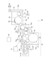
- FIG. 1 is a schematic plan view showing a content filling system according to one embodiment.
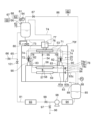
- FIG. 2 is a schematic diagram showing a filler of a content filling system according to one embodiment and the flow of fluid around the filler.
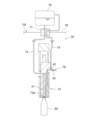
- FIG. 3 is a schematic cross-sectional view showing a filling nozzle of a filler of a content filling system according to one embodiment.
- FIG. 4 is a schematic cross-sectional view showing a filling nozzle of a filler of a content filling system according to a modified example.
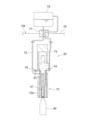
- FIG. 5 is a schematic cross-sectional view showing a filling nozzle of a filler of a content filling system according to a modified example.
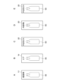
- 6A-6E are schematic flow diagrams illustrating a content filling method according to one embodiment.
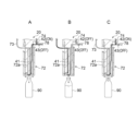
- 7A to 7E are cross-sectional views showing a content filling method (close filling) according to one embodiment.
- 8A to 8C are cross-sectional views showing a content filling method (top filling) according to a modified example.
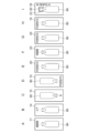
- 9A to 9I are schematic flow diagrams showing a content filling method according to a modified example.
- FIGs. 1 to 9 are diagrams illustrating one embodiment. In each of the following figures, the same parts are given the same reference numerals, and some detailed descriptions may be omitted.
- the content filling system 10 shown in FIG. 1 is a system for filling a bottle (container) 90 with a content such as a beverage.
- the bottle 90 is produced by biaxially stretching and blow molding a preform 91 produced by injection molding a synthetic resin material.
- the bottle 90 may also be produced by direct blow molding. It is preferable to use a thermoplastic resin, particularly PE (polyethylene), PP (polypropylene), PET (polyethylene terephthalate), or PEN (polyethylene naphthalate), as the material for the bottle 90.
- the container may be glass, a can, paper, a pouch, a cup, or a composite container of these.
- a plastic bottle is used as the container.
- the plastic bottle may be a pressure-resistant bottle for carbonated beverages, or a non-pressure-resistant bottle for non-carbonated beverages.
- the content filling system 10 includes a container sterilization device 11 and a filler (filling device) 20.
- the container sterilization device 11 is a device that pre-sterilizes bottles 90 before they are filled with the contents.
- the filler 20 is a device that fills the bottles 90 that have been sterilized by the container sterilization device 11 with the contents.
- the content filling system 10 comprises a bottle forming section 30, the above-mentioned container sterilizing device 11, the air-rinsing device 14, the above-mentioned filler 20, a capping device (capper, seaming and corking machine) 16, and a product bottle carrying section 19.
- the bottle forming section 30, the container sterilizing device 11, the air-rinsing device 14, the filler 20, the capping device 16, and the product bottle carrying section 19 are arranged in this order from the upstream side to the downstream side along the conveying direction of the bottles 90.
- a plurality of conveying wheels 12 are provided between the air-rinsing device 14, the filler 20, the capping device 16, etc., to convey the bottles 90 between these devices.
- the bottle forming section 30, the container sterilizing device 11, the air-rinsing device 14, the filler 20, the capping device 16, and the product bottle carrying section 19 will be described.
- the bottle molding section 30 receives preforms 91 from outside and molds bottles 90.
- the bottle molding section 30 transports the molded bottles 90 toward the container sterilization device 11. This allows the contents filling system 10 to continuously carry out processes from supplying the preforms 91 through molding the bottles 90, to filling the bottles 90 with the contents and capping them. In this case, small-volume preforms 91 are transported from outside to the contents filling system 10, rather than large-volume bottles 90. This allows for reduced transportation costs.
- An injection molding machine (not shown) may be connected to the bottle molding section 30 to manufacture the preforms 91 from resin pellets. In this case, transportation costs can be further reduced compared to transporting the preforms 91 from outside.
- the bottle molding section 30 has a preform conveying section 31, a blow molding section (container molding device) 32, and a bottle conveying section 33.
- the preform conveying section 31 conveys preforms 91.
- the blow molding section 32 molds bottles 90 by blow molding the preforms 91 sent from the preform conveying section 31.
- the bottle conveying section 33 conveys the bottles 90 molded in the blow molding section 32.
- the preform transport section 31 includes a preform receiving section 34, a preform heating section 35, and a preform delivery section 36.
- the preform receiving section 34 receives preforms 91 supplied from a preform supply device 37.
- the preform receiving section 34 is provided with a preform sterilizer 34a and a preform air-rinsing device 34b.
- the preform sterilizer 34a sterilizes the preforms 91.
- the preform air-rinsing device 34b air-rinses the preforms 91.
- the preform sterilizing device 34a sprays gas or mist of hydrogen peroxide solution onto the preform 91 to sterilize the preform 91 (pre-sterilization).
- the sterilizing agent for sterilizing the preform 91 may have the property of inactivating microorganisms.
- the sterilizing agent include hydrogen peroxide, peracetic acid, acetic acid, pernitric acid, nitric acid, chlorine-based chemicals, sodium hydroxide, potassium hydroxide, alcohols such as ethyl alcohol and isopropyl alcohol, chlorine dioxide, ozone water, acidic water, and surfactants, which may be used alone or in combination of two or more of these.
- preform sterilization device 34a sterilizing preforms 91 in advance (pre-sterilization)
- the amount of bacteria adhering to bottles 90 made from preforms 91 can be reduced. This makes it possible to reduce the amount of hydrogen peroxide used by container sterilization device 11 to sterilize bottles 90, and shorten the sterilization time.
- the amount of sterilant used to sterilize preforms 91 which have a small volume, can be less than the amount of sterilant used to sterilize bottles 90. Therefore, by pre-sterilizing preforms 91, the overall amount of sterilant used can be reduced.
- the amount of hydrogen peroxide used in the container sterilization device 11 can be reduced, and the sterilization time can be shortened, so the container sterilization device 11 can be made smaller.
- the sterilization time for sterilizing the bottles 90 can be shortened, so the thermal load on the bottles 90 can be reduced. Therefore, even if the bottles 90 are lightweight or made of recycled PET, deformation of the bottles 90 due to the heat of the sterilizing agent can be suppressed.
- Such sterilization treatment may be performed not only in the preform receiving section 34, but also in the preform heating section 35 or the preform delivery section 36.
- the sterilization treatment may be performed between the bottle conveying section 33 and the filler 20 after the bottle 90 has been formed.
- the sterilization treatment may be performed at multiple locations. Note that in the sterilization treatment, bacteria may be inactivated by ultraviolet irradiation or electron beam irradiation, etc., without using a disinfectant.
- the above-mentioned preform air rinse device 34b is provided downstream of the preform sterilizer 34a.
- the preform 91 sprayed with the sterilant is dried with hot air in the preform air rinse device 34b.
- the preform air rinse device 34b does not have to be provided in the preform receiving section 34.
- a foreign matter removal device (not shown) for removing foreign matter attached to the preform 91 may be provided upstream of the preform sterilizer 34a in the preform receiving section 34.
- the preform heating section 35 receives the preform 91 from the preform receiving section 34, and heats the preform 91 while transporting it.
- the preform heating section 35 is provided with a heater 35a that heats the preform 91.
- the heater 35a may be, for example, an infrared heater.
- the heater 35a heats the preform 91 to, for example, about 90°C or higher and 130°C or lower.
- the temperature of the mouth of the preform 91 is kept below 70°C to prevent deformation, etc.
- the preform delivery section 36 receives the preform 91 heated by the preform heating section 35 and delivers it to the blow molding section 32.
- the blow molding section 32 includes a mold (not shown).
- the preform 91 is blow molded using this mold to form a bottle 90.
- the molded bottle 90 is transported downstream by the bottle transport section 33.
- an adjustment conveying section 38 that receives the bottles 90 from the bottle conveying section 33 and transfers the bottles 90 to the container sterilization device 11. At least a portion of the adjustment conveying section 38 is housed inside an atmosphere blocking chamber 70c (described later) provided upstream of the sterilant spray chamber 70d (described later). In the illustrated example, the adjustment conveying section 38 is disposed so as to straddle the molding section chamber 70b (described later) that houses the bottle molding section 30 and the atmosphere blocking chamber 70c.
- the container sterilizer 11 is a device that sterilizes the bottles 90 by spraying a sterilizing agent onto the bottles 90.
- the container sterilizer 11 sterilizes the bottles 90 with a sterilizing agent before filling the bottles with the contents.
- a sterilizing agent for example, an aqueous hydrogen peroxide solution is used as the sterilizing agent.
- gas or mist of the aqueous hydrogen peroxide solution is generated, and the gas or mist is sprayed onto the inner and outer surfaces of the bottles 90. In this way, the bottles 90 are sterilized with gas or mist of the aqueous hydrogen peroxide solution, so that the inner and outer surfaces of the bottles 90 are sterilized evenly.
- the air rinse device 14 is a device that supplies sterile heated air or sterile room temperature air from a nozzle to the bottle 90 sterilized by the container sterilization device 11.
- the temperature of the heated air or room temperature air may be 30°C or higher and 180°C or lower, and preferably 50°C or higher and 140°C or lower.
- the volume of the heated air or room temperature air may be 50 L/min or higher and 500 L/min or lower per nozzle, and preferably 100 L/min or higher and 400 L/min or lower.
- the inner diameter of the nozzle may be ⁇ 2 mm or higher and ⁇ 10 mm or lower, and preferably ⁇ 4 mm or higher and ⁇ 8 mm or lower.
- the air rinse device 14 can remove foreign matter and hydrogen peroxide from inside the bottle 90 while activating the hydrogen peroxide. At this time, it is preferable that sterile air is supplied to the bottle 90 with the mouth of the bottle 90 facing downward. This allows foreign matter to be effectively removed from inside the bottle 90. This eliminates the need to wash the bottle 90 with sterile water, saving water. It also reduces the amount of carbon dioxide emitted by the content filling system 10. If necessary, the hydrogen peroxide can be gasified by mixing sterile room temperature air with a condensed mist of low concentration hydrogen peroxide, and the gas can be supplied to the bottle 90.
- the filler 20 is a device that fills bottles 90 with contents such as beverages. That is, the filler 20 fills the bottles 90 with contents from the mouths of the bottles 90. In this way, the contents are filled into the empty bottles 90 in the filler 20. In this filler 20, the contents are filled into the bottles 90 while the multiple bottles 90 are rotated and transported.
- the filler 20 is disposed inside a sterile chamber 70f, which will be described later.
- the filler 20 may be a so-called rotary filler having multiple rotatable filling nozzles 72, or may be a filler that transports the bottles 90 in a linear manner. In this embodiment, as will be described later, the bottles 90 are filled with an inert gas together with the contents in the filler 20. The details of the filler 20 will be described later.
- the capping device 16 is a device that caps the bottles 90 by attaching caps 92 to the bottles 90.
- the bottles 90 filled with the contents are closed with the caps 92. This seals the bottles 90 to prevent outside air and microorganisms from entering.
- the caps 92 are attached to the mouths of multiple bottles 90 filled with the contents while rotating (revolving) the caps 92 while gripping the bottles 90. By attaching the caps 92 to the bottles 90, product bottles 95 are obtained.
- the caps 92 are sterilized in advance by the cap sterilizer 18.
- the cap sterilizer 18 is arranged, for example, outside the sterile chamber 70f and near the cap fitting device 16.
- a large number of caps 92 brought in from outside the content filling system 10 are collected in advance and transported in a line toward the cap fitting device 16.
- hydrogen peroxide gas or mist is sprayed against the inner and outer surfaces of the caps 92, and then the caps are dried and sterilized with hot air.
- the product bottle discharge section 19 continuously discharges product bottles 95, which have caps 92 attached by the cap attachment device 16, to the outside of the content filling system 10.
- the content filling system 10 has a preform sterilization chamber 70a, a molding section chamber 70b, an atmosphere blocking chamber 70c, a disinfectant spray chamber 70d, an air rinse chamber 70e, a sterile chamber 70f, and an exit chamber 70g.
- the preform sterilization chamber 70a, the molding section chamber 70b, the atmosphere blocking chamber 70c, the disinfectant spray chamber 70d, the air rinse chamber 70e, the sterile chamber 70f, and the exit chamber 70g are arranged in this order from the upstream side to the downstream side along the conveying direction of the preforms 91 and the bottles 90.
- Each of the chambers 70a to 70g is separated by a partition wall.
- the partition wall prevents the disinfectant or the like from flowing in an unintended direction between the chambers 70a to 70g, and serves to stabilize the pressure within each of the chambers 70a to 70g.
- the partition wall has a gap large enough for the preform 91 or bottle 90 to pass through. This gap is formed to a minimum size, for example, the size of one preform 91 or bottle 90, so that the pressure within each of the chambers 70a to 70g does not change.
- the partition wall may be provided with a shutter that closes the above-mentioned gap. This shutter may be configured to open and close automatically, for example, in response to a signal from the control unit 60.
- the preform sterilization chamber 70a houses the preform sterilization device 34a and the like.
- the molding section chamber 70b houses the blow molding section 32 of the bottle molding section 30 and the like.
- the atmosphere blocking chamber 70c houses at least a part of the adjustment and conveying section 38.
- the sterilant spray chamber 70d houses the container sterilization device 11.
- the air rinse chamber 70e houses the air rinse device 14.
- the aseptic chamber 70f houses the filler 20, the conveying wheel 12, and the capping device 16.
- the exit chamber 70g houses the product bottle discharge section 19.
- the content filling system 10 further includes a control unit 60 that controls the content filling system 10.
- the control unit 60 is electrically connected to the bottle molding unit 30, the container sterilization device 11, the air rinse device 14, the filler 20, the cap attachment device 16, the product bottle conveying unit 19, and the cap sterilization device 18, and may control some or all of these devices.
- the content filling system 10 may be, for example, a sterile filling system.
- the insides of the germicide spray chamber 70d, the air rinse chamber 70e, the sterile chamber 70f, and the exit chamber 70g are kept in a sterile state.
- a chamber (not shown) may be provided downstream of the exit chamber 70g to connect a sterile zone in a sterile state with a non-sterile zone in a non-sterile state.
- the content filling system 10 may be a non-sterile filling system.
- the filler 20 is provided in a sterile chamber 70f.
- a content filling tank 75 is provided outside the sterile chamber 70f and above the filler 20.
- the content filling tank 75 may be called a filling head tank or a buffer tank.
- the content filling tank 75 is filled with a content such as a beverage.
- the beverage may be a carbonated beverage or a non-carbonated beverage.
- the content filling tank 75 is connected to a sterile carbon dioxide supply unit 63 via a carbon dioxide gas supply line 61.
- a first valve 62 is provided on the carbon dioxide gas supply line 61. By opening the first valve 62, sterile carbon dioxide gas is supplied from the sterile carbon dioxide supply unit 63 to the content filling tank 75.
- the carbonated beverage in the content filling tank 75 is pressurized by the sterile carbon dioxide gas. This makes it possible to prevent the carbon dioxide gas dissolved in the carbonated beverage from being released into the gas phase.
- the carbonated beverage is preferably pressurized at a pressure higher than the standard carbon dioxide pressure for production. This keeps the concentration of carbon dioxide in the carbonated beverage in the content filling tank 75 constant.
- the pressure P1 of the carbon dioxide in the content filling tank 75 is measured by a first pressure gauge 64 provided in the content filling tank 75. If the content filling system 10 does not fill a carbonated beverage, the carbon dioxide supply line 61 and the sterile carbon dioxide supply unit 63 do not need to be provided.
- the content filling tank 75 is connected to the inert gas supply unit 69 via the inert gas supply line 67.
- the inert gas supply line 67 is provided with a second valve 68. By opening the second valve 68, inert gas is supplied from the inert gas supply unit 69 to the content filling tank 75.
- a valve that serves both as the first valve 62 and the second valve 68 may be provided by connecting the part of the carbon dioxide gas supply line 61 on the sterile carbon dioxide supply unit 63 side to the part of the inert gas supply line 67 on the inert gas supply unit 69 side.
- the inert gas in the content filling tank 75 is supplied to the bottle 90 via the gas supply line 74 and the filling nozzle 72 in sequence, as described below.
- the pressure P1 of the inert gas in the content filling tank 75 is measured by the first pressure gauge 64 provided in the content filling tank 75.
- Nitrogen or argon may be used as the inert gas.
- the inert gas may be a sterile inert gas or a non-sterile inert gas. If the contents to be filled are sterile, a sterile inert gas may be used, and if the contents to be filled are non-sterile, a non-sterile inert gas may be used.
- the volume fraction of the inert gas in the space above the contents in the content filling tank 75 may be 90% or more, 95% or more, 99% or more, or 99.9% or more.
- the content introduction line 65 is connected to the content filling tank 75.
- the content introduction line 65 is connected to a content production device (not shown).
- a third valve 66 is provided on the content introduction line 65. By opening the third valve 66, the content such as the product liquid from the content production device passes through the content introduction line 65 and is filled into the content filling tank 75.
- the content introduction line 65 is connected to a CIP circulation line 81, which will be described later.
- a gas release line 86 is connected to the content-filled tank 75.
- the gas release line 86 is connected to the exhaust tank 85, which will be described later.
- a fourth valve 87 is provided on the gas release line 86. When the fourth valve 87 is opened, the inert gas or carbon dioxide gas in the content-filled tank 75 can be released toward the exhaust tank 85.
- the pressure P2 in the gas release line 86 is measured by a second pressure gauge 88 provided on the gas release line 86. This pressure P2 is equal to the pressure in the exhaust tank 85.
- the first valve 62 and the fourth valve 87 are controlled by the control unit 60, thereby controlling the pressure in the content-filled tank 75.
- the relationship P1>P2 is established between the pressure P1 in the content-filled tank 75 measured by the first pressure gauge 64 and the pressure P2 in the gas discharge line 86 measured by the second pressure gauge 88.
- the pressure P1 in the content-filled tank 75 may be controlled to be, for example, 0.01 MPa or more and 1.0 MPa or less.
- the pressure P2 in the gas discharge line 86 may be controlled to be a pressure slightly above 0 MPa, for example, 0.0001 MPa or more and 0.01 MPa or less. This makes it possible to prevent non-sterile gas from entering the content-filled tank 75 from outside the sterile chamber 70f. For this reason, a non-sterile tank that is not controlled to be in a sterile state can be used as the discharge tank 85.
- a content supply line 73 is connected to the content filling tank 75.
- the content supply line 73 is a line that supplies the contents, such as a beverage, filled in the content filling tank 75 toward the filling nozzle 72, which will be described later.
- the content filling tank 75 is connected to the filling nozzle 72 via the content supply line 73.
- a gas supply line 74 is connected to the content filling tank 75.
- the gas supply line 74 is a line that supplies the inert gas filled in the content filling tank 75 toward the filling nozzle 72 described below.
- the content filling tank 75 is connected to the filling nozzle 72 via the gas supply line 74. Note that if the content filling system 10 is a device capable of filling both carbonated and non-carbonated beverages, the gas supply line 74 can supply the carbon dioxide gas filled in the content filling tank 75 to the filling nozzle 72. In other words, the gas supply line 74 may selectively supply either carbon dioxide gas or an inert gas.
- the contents filled in the contents filling tank 75 are filled into empty bottles 90.
- the filler 20 has a conveyor wheel 71 that rotates around an axis parallel to the vertical direction. The contents are filled into the bottles 90 as the conveyor wheel 71 rotates (revolves) the multiple bottles 90.
- Multiple filling nozzles 72 are arranged along the outer periphery of the conveyor wheel 71. One bottle 90 is attached to each filling nozzle 72, and the contents are injected into the bottles 90 from the filling nozzle 72. The configuration of the filling nozzle 72 will be described later.
- the conveying wheel 71, the filling nozzle 72, at least a part of the content supply line 73, and at least a part of the gas supply line 74 are housed in a cover 76 that constitutes part of the sterile chamber 70f.
- a rotary joint 77 is attached to the top of the cover 76.
- the content supply line 73 and the gas supply line 74 are attached to the cover 76 of the sterile chamber 70f by the rotary joint 77.
- the rotary joint 77 seals the rotating body and the non-rotating body in a sterile state.
- the rotating body is, for example, the conveying wheel 71, the filling nozzle 72, and the rotating piping of the content supply line 73 and the gas supply line 74.
- the non-rotating body is, for example, the cover 76, and the fixed piping of the content supply line 73 and the gas supply line 74.
- a content supply line 73 and a gas supply line 74 are connected to each filling nozzle 72.
- One end of the content supply line 73 is connected to a content filling tank 75 filled with content.
- the other end of the content supply line 73 is connected to the inside of the bottle 90.
- the content supplied from the content filling tank 75 passes through the content supply line 73 and is injected into the inside of the bottle 90.
- One end of the gas supply line 74 is connected to the content filling tank 75.
- the other end of the gas supply line 74 is connected to the inside of the bottle 90.
- the inert gas supplied from the content filling tank 75 passes through the gas supply line 74 and is filled into the inside of the bottle 90.
- a gas branching section 53 is provided midway along the gas supply line 74.
- the gas supply line 74 from the content filling tank 75 is branched into multiple lines at the gas branching section 53 and extends to each filling nozzle 72.
- a snift line 78 is connected to each filling nozzle 72. One end of the snift line 78 is connected to the gas supply line 74. The other end of the snift line 78 extends outside the sterile chamber 70f. Gas inside the bottle 90 can be discharged through the snift line 78.
- a snift line branch 56 is provided midway along the snift line 78, and the inert gas from the snift line 78 is collected at the snift line branch 56 and discharged into the sterile chamber 70f.
- a discharge valve 79 is provided on the snift line 78 in the sterile chamber 70f.
- the discharge valve 79 discharges the inert gas from the snift line 78 into the sterile chamber 70f.
- the snift line branch 56 and the gas branch 53 are connected by a first bypass line 54.
- the first bypass line 54 is provided with a fifth valve 55, which is normally closed.
- the snift line 78 has an inner snift line 78a and an outer snift line 78b. One end of the inner snift line 78a is connected to the filling nozzle 72, and the other end is connected to a discharge valve 79.
- the inner snift line 78a is entirely located within the sterile chamber 70f, and the above-mentioned snift line branch 56 is located midway along the inner snift line 78a.
- the inner snift line 78a is of a rotating type that rotates together with the filling nozzle 72.
- the outer snift line 78b has one end connected to the discharge valve 79 and the other end open to the outside of the sterile chamber 70f. A part of the outer snift line 78b is located inside the sterile chamber 70f and the other part is located outside the sterile chamber 70f.
- the outer snift line 78b is a non-rotating type that does not rotate together with the filling nozzle 72.
- the discharge valve 79 is located between the inner snift line 78a and the outer snift line 78b.
- the inner snift line 78a and the outer snift line 78b are detachable at the discharge valve 79.
- the discharge valve 79 can be opened and closed, and is normally open. When the discharge valve 79 is open, the inner snift line 78a is physically separated from the outer snift line 78b, and the inner snift line 78a communicates with the inside of the sterile chamber 70f at the discharge valve 79.
- the inner snift line 78a When the discharge valve 79 is closed, the inner snift line 78a is connected to the outer snift line 78b, and the inner snift line 78a communicates with the outer snift line 78b. At this time, the inner snift line 78a does not communicate with the inside of the sterile chamber 70f.
- the outer snift line 78b is expandable and contractable at the bellows portion 78c.
- the bellows portion 78c of the outer snift line 78b contracts, and the outer snift line 78b detaches from the inner snift line 78a.
- the inner snift line 78a becomes rotatable and communicates with the sterile chamber 70f at the discharge valve 79.
- the discharge valve 79 is closed, the rotation of the inner snift line 78a is stopped, and the inner snift line 78a and the outer snift line 78b are positioned in the rotational direction.
- the bellows portion 78c of the outer snift line 78b is expanded, and the outer snift line 78b is connected to the inner snift line 78a at the discharge valve 79.
- the inner snift line 78a is integrated with the outer snift line 78b and communicates with the outer snift line 78b.
- the inert gas in the bottle 90 can be discharged into the sterile chamber 70f, which is a sterile space, without contamination with bacteria.
- a rotary joint for connecting the rotating snift line 78 to the outside of the sterile chamber 70f.
- Such rotary joints generally have a complex mechanism and are expensive. Therefore, by omitting the rotary joint for the snift line 78, the mechanism of the content filling system 10 can be simplified and manufacturing costs can be reduced.
- the flow path of the content filling system 10 through which the contents such as beverages pass is preferably subjected to CIP (Cleaning in Place) treatment and further to SIP (Sterilizing in Place) treatment.
- CIP treatment and SIP treatment may be performed periodically or when the type of contents is changed.
- the CIP treatment is performed by, for example, flowing a cleaning solution in which an alkaline agent such as caustic soda is added to water into the flow path from the inside of the pipeline of the route through which the raw materials are supplied to the filling nozzle 72 of the filler 20, and then flowing a cleaning solution in which an acidic agent is added to water. This removes residues of the previous contents that are attached to the flow path through which the contents pass.
- the SIP treatment is a treatment for sterilizing the flow path through which the contents pass before entering the content filling operation.
- the SIP treatment is performed, for example, by flowing heated steam or hot water into the flow path cleaned by the above CIP. This sterilizes the flow path through which the contents pass and makes it sterile.
- a CIP cup 82 is provided near the filling nozzle 72 to receive the cleaning liquid from the filling nozzle 72.
- a CIP line 83 is connected to this CIP cup 82.
- One end of the CIP line 83 is connected to the CIP cup 82.
- the other end of the CIP line 83 is connected to a discharge tank 85 arranged outside the sterile chamber 70f.
- the cleaning liquid from the filling nozzle 72 can be discharged to the discharge tank 85 via the CIP line 83.
- a CIP line branch 59 is provided in the middle of the CIP line 83.
- the cleaning liquid from the CIP line 83 is collected together at the CIP line branch 59 and discharged to the discharge tank 85.
- the CIP line branch 59 and the sniff line branch 56 are connected by a second bypass line 57.
- a sixth valve 58 is provided on the second bypass line 57. Normally, this sixth valve 58 is closed.
- the CIP line 83 has an inner CIP line 83a and an outer CIP line 83b.
- One end of the inner CIP line 83a is connected to the CIP cup 82.
- the other end of the inner CIP line 83a is connected to a connection valve 84.
- the entire inner CIP line 83a is located within the sterile chamber 70f, and the above-mentioned CIP line branch 59 is located midway along the inner CIP line 83a.
- the inner CIP line 83a is of a rotary type that rotates together with the filling nozzle 72.
- One end of the outer CIP line 83b is connected to the connection valve 84.
- the other end of the outer CIP line 83b is connected to the discharge tank 85.
- a part of the outer CIP line 83b is located inside the sterile chamber 70f, and the remaining part is located outside the sterile chamber 70f.
- the outer CIP line 83b is of a non-rotating type, and does not rotate together with the filling nozzle 72.
- the connection valve 84 is located between the inner CIP line 83a and the outer CIP line 83b.
- the inner CIP line 83a and the outer CIP line 83b are detachable at the connection valve 84.
- the connection valve 84 can be opened and closed, and is normally open.
- the connection valve 84 is open, the inner CIP line 83a is physically separated from the outer CIP line 83b.
- the inner CIP line 83a communicates with the inside of the sterile chamber 70f at the connection valve 84.
- the connection valve 84 is closed, the inner CIP line 83a is connected to the outer CIP line 83b.
- the inner CIP line 83a communicates with the discharge tank 85 via the outer CIP line 83b.
- connection valve 84 may be substantially the same as the configuration of the discharge valve 79 described above.
- the inert gas sent from the sniff line 78 may be discharged from the connection valve 84 into the sterile chamber 70f by opening the sixth valve 58.
- the outer CIP line 83b is expandable at the bellows portion 83c.
- the bellows portion 83c of the outer CIP line 83b contracts, and the outer CIP line 83b is separated from the inner CIP line 83a at the connection valve 84.
- the inner CIP line 83a becomes rotatable and communicates with the inside of the aseptic chamber 70f.
- the connection valve 84 is closed, the inner CIP line 83a and the outer CIP line 83b are positioned in the rotational direction.
- the bellows portion 83c of the outer CIP line 83b is expanded, and the outer CIP line 83b is connected to the inner CIP line 83a at the connection valve 84.
- the inner CIP line 83a is integrated with the outer CIP line 83b and communicates with the outer CIP line 83b.
- An exhaust line 89 is provided at the top of the discharge tank 85 to exhaust the gas inside the discharge tank 85.
- a scrubber (not shown) that processes the gas is connected to the exhaust line 89.
- the above-mentioned CIP circulation line 81 is connected to the bottom of the discharge tank 85.
- the CIP circulation line 81 is a line that sends the cleaning liquid stored in the discharge tank 85 toward the content filling tank 75 side and circulates it.
- the CIP circulation line 81 connects the discharge tank 85 to the middle of the content introduction line 65.
- the CIP circulation line 81 is provided with a cleaning liquid supply unit 94, a pump 98, a seventh valve 99, a heater 93, and an eighth valve 101 in this order from the discharge tank 85 side.
- a drain line 96 is connected between the pump 98 and the seventh valve 99.
- a ninth valve 97 is provided on the drain line 96.
- the drainage line 96 may be provided between the heater 93 and the eighth valve 101, and additional drainage lines 96 may be provided as needed in locations where residual water in each pipe can be quickly removed.
- the cover 76 of the sterile chamber 70f is provided with a sterile air supply device 80 that sends a large volume of sterile air into the sterile chamber 70f.
- the sterile air supply device 80 introduces sterile air into the sterile chamber 70f, thereby maintaining a positive pressure inside the sterile chamber 70f and preventing outside air from entering the sterile chamber 70f.
- a large volume of sterile air is sent into the sterile chamber 70f by the sterile air supply device 80. Therefore, even if inert gas is discharged into the sterile chamber 70f from the exhaust valve 79 as described above, the concentration of inert gas in the sterile chamber 70f does not increase excessively.
- the filling nozzle 72 has a main body 72a.
- a content supply line 73 and a gas supply line 74 are connected to the main body 72a.
- the upper end of the content supply line 73 is connected to a content filling tank 75.
- the lower end of the content supply line 73 is connected to the inside of the bottle 90.
- the main body 72a is provided with a filling valve 41.
- When the filling valve 41 is open the content supplied from the content filling tank 75 passes through the content supply line 73 and is injected into the inside of the bottle 90.
- the filling valve 41 is closed, the injection of the content from the content supply line 73 to the bottle 90 stops.
- the inner diameter of the part of the filling valve 41 where the content is added may be 6 mm or more and 20 mm or less, or 8 mm or more and 15 mm or less.
- the filling nozzle 72 can be raised and lowered relative to the bottle 90. When the filling nozzle 72 is lowered, it comes into contact with the mouth of the bottle 90. In this case, the contents are filled into the bottle 90 with the filling nozzle 72 in contact with the bottle 90 (close contact filling, Figures 7A-7E). When the filling nozzle 72 is raised, it moves away from the mouth of the bottle 90. Note that the contents may be filled into the bottle 90 with the filling nozzle 72 separated from the bottle 90 (above-mouth filling, Figures 8A-8C).
- the filling nozzle 72 may have a vent tube (not shown).
- the upper end of the gas supply line 74 is connected to the content filling tank 75.
- the lower end of the gas supply line 74 is connected to the inside of the bottle 90.
- the inert gas supplied from the content filling tank 75 passes through the gas supply line 74 and is filled into the inside of the bottle 90.
- a snift line 78 is connected to the middle of the gas supply line 74.
- the inert gas inside the bottle 90 can be discharged via the snift line 78.
- the gas supply line 74 supplies the carbon dioxide gas filled in the content filling tank 75 to the filling nozzle 72.
- the gas supply line 74 is provided with a gas valve 42.
- the gas valve 42 When the gas valve 42 is open, the inert gas supplied from the content filling tank 75 passes through the gas supply line 74 and the filling nozzle 72 and is injected into the bottle 90.
- the gas valve 42 When the gas valve 42 is closed, the injection of the inert gas from the gas supply line 74 and the filling nozzle 72 to the bottle 90 stops.
- the inner diameter of the part of the gas valve 42 where the inert gas is added may be 2 mm or more and 10 mm or less, or 3 mm or more and 8 mm or less.
- the gas supplied from the filling nozzle 72 to the bottle 90 may contain a small amount of gas other than the inert gas.
- the volume fraction of the inert gas in the gas supplied from the filling nozzle 72 to the bottle 90 may be 90% or more, 95% or more, 99% or more, or 99.9% or more.
- the snift line 78 is provided with a snift valve 43.
- the inert gas from the bottle 90 passes through the snift line 78 and is discharged to the outside of the filler 20.
- the snift valve 43 is closed, the discharge of the inert gas from the bottle 90 is interrupted.
- the inner diameter of the part of the snift valve 43 where the inert gas is added may be 2 mm or more and 10 mm or less, or 3 mm or more and 8 mm or less.
- the content supply line 73 and the gas supply line 74 pass through a rotary joint 77 provided on the cover 76.
- the sniff line 78 discharges the inert gas from the sniff line 78 into the sterile chamber 70f without using a rotary joint as described above.
- the snift line 78 does not have to be connected midway through the gas supply line 74.
- the tip of the snift line 78 may be located at the tip of the filling nozzle 72, similar to the tip of the gas supply line 74. In this case, it is preferable to provide the tip of the snift line 78 at a position diagonal to the gas supply line 74 with respect to the central axis of the filling nozzle 72. This can improve the efficiency of replacing the inert gas in the bottle 90.
- the inert gas may be supplied to the bottle 90 from the inert gas supply pipe 46 instead of the gas supply line 74.
- the tip of the inert gas supply pipe 46 is connected to the filling nozzle 72.
- the inert gas supply pipe 46 feeds the inert gas into the filler 20 from outside the filler 20.
- the base end of the inert gas supply pipe 46 (the end opposite the filling nozzle 72) may be connected to, for example, the inert gas supply unit 69.
- the inert gas supply pipe 46 is not connected to the content filling tank 75. The inert gas is filled into the bottle 90 from the inert gas supply pipe 46 via the filling nozzle 72.
- the gas supply line 74 is used exclusively to fill the bottle 90 with carbon dioxide gas.
- the inert gas supply pipe 46 may be arranged via a rotary joint different from the rotary joint 77 provided at the top or bottom of the filler 20. According to the example shown in FIG. 5, when filling the bottle 90 with inert gas, the air in the bottle 90 is prevented from flowing back toward the content filling tank 75. As a result, the concentration of the inert gas in the content filling tank 75 does not decrease, and the replacement rate of the inert gas is prevented from decreasing.
- a content filling method using the above-mentioned content filling system 10 (FIG. 1) will be described below.
- a normal filling method that is, a content filling method for filling a bottle 90 with content to produce a product bottle 95, will be described below.
- a plurality of preforms 91 are sequentially supplied to the preform receiving section 34 of the preform transport section 31 by the preform supplying device 37.
- the preforms 91 are sterilized in the preform sterilizing device 34a by spraying hydrogen peroxide gas or mist onto them, and then dried with hot air.
- the preform 91 is then sent to the preform heating section 35, where it is heated by the heater 35a, for example, to a temperature of 90°C or higher and 130°C or lower.
- the preform 91 heated by the preform heating section 35 is sent to the preform delivery section 36.
- the preform 91 is then sent from the preform delivery section 36 to the blow molding section 32.
- the preform 91 sent to the blow molding section 32 is blow molded using a mold (not shown) to form a bottle 90.
- the blow molded bottle 90 is then sent to the bottle conveying section 33.
- the bottle 90 is sterilized using a hydrogen peroxide solution as a sterilizing agent (see FIG. 6A).
- the sterilizing agent may be a gas or mist obtained by vaporizing the hydrogen peroxide solution at or above its boiling point.
- the hydrogen peroxide solution gas or mist adheres to the inner and outer surfaces of the bottle 90, sterilizing the inner and outer surfaces of the bottle 90.
- the hydrogen peroxide solution may be a gas or mist obtained by condensing an aqueous hydrogen peroxide solution having a concentration of 1% by weight or more, preferably 35% by weight, after it has been vaporized.
- the bottle 90 is sent to the air rinse device 14 and air-rinsed (see FIG. 6B).
- sterile heated air or sterile room temperature air is supplied to the bottle 90. This activates the hydrogen peroxide and removes foreign matter and hydrogen peroxide from the bottle 90.
- a condensed mist of low concentration hydrogen peroxide may be mixed with the sterile heated air or sterile room temperature air as necessary.
- the hydrogen peroxide is gasified by the sterile air.
- the gasified hydrogen peroxide may be supplied to the bottle 90.
- the air for air rinsing may be changed to an inert gas such as nitrogen gas.
- the bottles 90 that have been air-rinsed by the air-rinsing device 14 are transported by the transport wheel 12 to the filler 20.
- the bottles 90 are rotated (revolved) while the contents are filled into the bottles 90 from their mouths.
- the contents sent from the contents filling tank 75 are filled into the sterilized bottles 90 at a filling temperature of 1°C or higher and 40°C or lower, preferably 5°C or higher and 30°C or lower.
- a bottle 90 is supplied to the filler 20, and the bottle 90 is positioned below the corresponding filling nozzle 72.
- the filling nozzle 72 is positioned above the bottle 90, and the filling nozzle 72 is separated from the mouth of the bottle 90.
- the filling valve 41 is closed, and the gas valve 42 is open. This allows the gas supply line 74 and the bottle 90 to communicate with each other.
- the sniff valve 43 is closed.
- inert gas is supplied from the content filling tank 75 via the gas supply line 74, and the inert gas is sent into the bottle 90.
- the inside of the bottle 90 which was previously filled with air, is replaced with the inert gas. In this way, the bottle 90 is filled with inert gas before the contents are filled into the bottle 90.
- the filling nozzle 72 descends and contacts the mouth of the bottle 90.
- the time for the filling nozzle 72 to descend may be 0.2 seconds or more and 1.0 seconds or less.
- the filling valve 41 is closed and the gas valve 42 is opened.
- the sniff valve 43 is open.
- inert gas is supplied from the content filling tank 75 through the gas supply line 74 and the filling nozzle 72, and the inert gas is sent into the bottle 90 (see FIG. 6C). This ensures that the inside of the bottle 90 is replaced with inert gas while the inside of the bottle 90 is isolated from the outside air.
- the excess inert gas from the content filling tank 75 that cannot be filled into the bottle 90 is discharged to the outside through the sniff line 78.
- the inert gas from the bottle 90 passes through the sniff line 78 and is then discharged from the discharge valve 79 into the sterile chamber 70f.
- the process shown in FIG. 7B may be performed for 0.2 seconds or more and 2.0 seconds or less, and is preferably performed for 0.3 seconds or more and 1.0 seconds or less.
- the supply rate of inert gas from the filling nozzle 72 may be 50 L/min/tube or more and 800 L/min/tube or less.
- the contents are filled into the bottle 90 from the filling nozzle 72.
- the contents are injected into the bottle 90 from the contents filling tank 75 through the contents supply line 73 and the filling nozzle 72.
- the filling valve 41 is opened and the gas valve 42 is closed.
- the sniff valve 43 is open.
- the gas valve 42 is closed, and the supply of inert gas from the contents filling tank 75 to the bottle 90 is stopped.
- the contents are filled into the bottle 90 from the filling nozzle 72, and the inert gas present inside the bottle 90 is replaced with the contents (see FIG. 6D).
- the inert gas replaced with the contents inside the bottle 90 is discharged to the outside through the sniff line 78.
- one or more small-dose fillings and one or more large-dose fillings may be performed. For example, a small-dose filling may be performed first, followed by a large-dose filling, and then a small-dose filling may be performed. Alternatively, only one of small-volume filling and large-volume filling may be performed. Small-volume filling refers to filling with a small amount of material per unit time, and large-volume filling refers to filling with a large amount of material per unit time.
- the process shown in FIG. 7C may be performed for 2 seconds or more and 20 seconds or less.
- the filling flow rate of the contents at this time may be 30 ml/sec or more and 300 ml/sec or less, and is preferably 60 ml/sec or more and 200 ml/sec or less.
- the supply of contents from the filling nozzle 72 to the bottle 90 is stopped.
- the bottle 90 is left stationary for a certain period of time. This reduces air bubbles that are generated in the contents due to the force of the supply from the filling nozzle 72.
- the filling valve 41 is closed and the gas valve 42 is opened.
- the sniff valve 43 is open.
- inert gas is supplied from the contents filling tank 75 to the bottle 90 (see FIG. 6E). This ensures that the air remaining in the head space of the bottle 90 is replaced with the inert gas.
- the excess inert gas that cannot be filled into the bottle 90 is discharged to the outside through the sniff line 78. In this way, after the contents are filled into the bottle 90, the inert gas is filled into the bottle 90.
- the process shown in FIG. 7D may be performed for 0.2 seconds or more and 2.0 seconds or less, and preferably for 0.3 seconds or more and 1.0 seconds or less.
- the supply rate of inert gas from the filling nozzle 72 may be 50 L/min/tube or more and 800 L/min/tube or less.
- the filling nozzle 72 rises and moves away from the mouth of the bottle 90.
- the time it takes for the filling nozzle 72 to rise may be 0.2 seconds or more and 1.0 seconds or less.
- the filling valve 41 is closed and the gas valve 42 is open.
- the sniff valve 43 is closed.
- inert gas is supplied from the content filling tank 75 via the gas supply line 74 and sent into the bottle 90. This prevents air from entering the inside of the bottle 90 even when the filling nozzle 72 moves away from the mouth of the bottle 90 and the inside of the bottle 90 is connected to the outside air.
- the bottle 90 filled with the content is then discharged from the filler 20.
- the bottle 90 is filled with inert gas before and after the contents are filled into the bottle 90.
- the bottle 90 may be filled with inert gas only at one of the timings, either before or after the contents are filled into the bottle 90.
- the filling nozzle 72 is lowered and raised, but this is not a limitation.
- the filling nozzle 72 may be fixed and the container 90 may be raised and lowered to bring the tip of the filling nozzle 72 into contact with or away from the container 90. Alternatively, both the filling nozzle 72 and the container 90 may be moved.
- the bottle 90 filled with the contents by the filler 20 is transported to the capping device 16 by the transport wheel 12.
- the cap 92 is sterilized in advance by the cap sterilizer 18.
- the cap 92 sterilized by the cap sterilizer 18 is attached to the mouth of the bottle 90 transported from the filler 20 by the cap attachment device 16. This results in a product bottle 95 having the bottle 90 and the cap 92.
- the product bottle 95 is then transported from the capping device 16 to the product bottle discharge section 19 and transported outside the content filling system 10.
- All steps from sterilizing the bottles 90 to attaching the caps 92 are carried out in a sterile atmosphere surrounded by the sterile chamber 70f, i.e., in a sterile environment.
- Positive pressure sterile air may be supplied from the sterile air supply device 80 into the sterile chamber 70f so that sterile air is constantly blown out of the sterile chamber 70f.
- the production (conveying) speed of the bottles 90 in the content filling system 10 is 100 bpm or more and 1500 bpm or less.
- bpm bottle per minute refers to the conveying speed of the bottles 90 per minute.
- the inert gas is filled into the bottle 90 in the filler 20.
- This can reduce the initial amount of oxygen in the bottle 90, and suppress oxidative deterioration of the contents.
- the time from filling the bottle 90 with the inert gas to filling the contents can be shortened. This can minimize leakage of the inert gas in the bottle 90 to the outside from filling the bottle 90 with the inert gas to filling the contents.
- the replacement rate of the inert gas in the bottle 90 can be improved, and the oxygen remaining in the bottle 90 can be reduced.
- the filler 20 fills the bottle 90 with an inert gas before filling the bottle 90 with the contents.
- the replacement rate of the inert gas in the bottle 90 can be improved, and the oxygen remaining in the bottle 90 can be reduced.
- the bottle 90 is filled with an inert gas.
- This allows the air remaining in the head space above the contents to be replaced with the inert gas after the contents are filled. This minimizes the inflow of air into the head space of the bottle 90 until the cap 92 is attached by the cap attachment device 16.
- the replacement rate of the inert gas in the bottle 90 can be improved, and the amount of oxygen remaining in the bottle 90 can be reduced.
- the content filling tank 75 is filled with inert gas and contents.
- the inert gas is filled into the bottle 90 from the content filling tank 75 via the filling nozzle 72.
- This allows the inert gas to be supplied into the bottle 90 by using the existing content filling tank 75.
- This eliminates the need to prepare a separate tank for filling the inert gas, thereby reducing the manufacturing cost of the content filling system 10.
- By filling the content filling tank 75 with inert gas dissolution of oxygen into the contents in the content filling tank 75 is suppressed.
- the filler 20 has a snift line 78 connected to the filling nozzle 72. A portion of the inert gas is discharged from the snift line 78. This prevents the inside of the bottle 90 from being significantly pressurized by the pressure of the inert gas. For this reason, a non-pressure-resistant bottle can be used as the bottle 90.
- the content filling system 10 is a device capable of selectively filling carbonated beverages and non-carbonated beverages
- the inert gas can be discharged from inside the bottle 90 by utilizing the existing snift line 78. This eliminates the need to prepare a separate exhaust path for discharging the inert gas, thereby reducing the manufacturing cost of the content filling system 10.
- the filler 20 has a sterile chamber 70f that houses the filling nozzle 72, and a portion of the inert gas (excess inert gas that cannot be filled into the bottle 90) is discharged into the sterile chamber 70f.
- the rotary joint for the snift line 78 can be omitted, simplifying the overall configuration of the content filling system 10.
- the manufacturing cost of the content filling system 10 can be reduced.
- a bottle 90 is supplied to the filler 20, and the bottle 90 is positioned below the corresponding filling nozzle 72. At this time, the filling nozzle 72 is separated from the mouth of the bottle 90.
- the filling valve 41 is closed, and the gas valve 42 is open. This allows the gas supply line 74 and the bottle 90 to communicate with each other.
- the sniff valve 43 is closed.
- inert gas is supplied from the content filling tank 75 via the gas supply line 74 and the filling nozzle 72, and the inert gas is sent into the bottle 90.
- the inside of the bottle 90 which was previously filled with air, is replaced with the inert gas. In this way, the bottle 90 is filled with inert gas before the contents are filled into the bottle 90.
- the process shown in FIG. 8A may be performed for 0.2 seconds or more and 2.0 seconds or less, and preferably for 0.3 seconds or more and 1.0 seconds or less.
- the supply rate of the inert gas at this time may be 50 L/min/tube or more and 800 L/min/tube or less.
- the contents are filled into the bottle 90 from the filling nozzle 72.
- the filling nozzle 72 is maintained away from the mouth of the bottle 90.
- the contents are injected into the bottle 90 from the contents filling tank 75 through the contents supply line 73 and the filling nozzle 72.
- the filling valve 41 is opened and the gas valve 42 is closed.
- the sniff valve 43 is closed.
- the gas valve 42 is closed, and the supply of inert gas from the contents filling tank 75 to the bottle 90 is stopped. Meanwhile, the inert gas present inside the bottle 90 is replaced with the contents.
- the inert gas replaced with the contents inside the bottle 90 is discharged to the outside from the mouth of the bottle 90.
- one or more small-dose fillings and one or more large-dose fillings may be performed. For example, a small-dose filling may be performed first, followed by a large-dose filling, and then a small-dose filling may be performed.
- the process shown in FIG. 8B may be performed for 2 seconds or more and 20 seconds or less.
- the filling flow rate of the contents at this time may be 30 ml/sec or more and 300 ml/sec or less, and is preferably 60 ml/sec or more and 200 ml/sec or less.
- the supply of contents from the filling nozzle 72 to the bottle 90 is stopped.
- the filling valve 41 is closed and the gas valve 42 is opened.
- the sniff valve 43 is closed.
- inert gas is supplied from the contents filling tank 75 to the bottle 90. This ensures that any air remaining in the head space of the bottle 90 is replaced with the inert gas. Meanwhile, any excess inert gas that cannot be filled into the bottle 90 is discharged to the outside from the mouth of the bottle 90. In this way, after the contents are filled into the bottle 90, the inert gas is filled into the bottle 90.
- the bottle 90 filled with the contents is then discharged from the filler 20.
- the process shown in FIG. 8C may be performed for 0.2 seconds or more and 2.0 seconds or less, and preferably for 0.3 seconds or more and 1.0 seconds or less.
- the supply rate of the inert gas at this time may be 50 L/min/tube or more and 800 L/min/tube or less.
- the bottle 90 is filled with an inert gas before filling the bottle 90 with the contents and after filling the bottle 90 with the contents.
- the bottle 90 may be filled with an inert gas only at one of the timings, either before filling the bottle 90 with the contents or after filling the bottle 90 with the contents.
- an inert gas may be filled into the bottle 90 along with the contents.
- the contents are filled while incorporating the inert gas therein.
- the inert gas is released from the contents into the head space, thereby preventing a decrease in the concentration of the inert gas in the head space.
- the sniff line 78 may not be provided.
- the content filling system 10 may be a filling system dedicated to non-carbonated beverages.
- FIGS. 9A-9I are schematic flow diagrams showing a modified content filling method.
- the bottle 90 in addition to the filler 20, the bottle 90 is filled with inert gas by a device other than the filler 20.
- the same parts as those shown in FIG. 1 to FIG. 8 are given the same reference numerals and detailed explanations are omitted.
- the container sterilization device 11 a sterilization process is performed on the bottle 90 (see FIG. 9A).
- the air rinse device 14 the bottle 90 before being filled with the contents by the filler 20 is air-rinsed (see FIG. 9B).
- the air for the air rinse may be changed to an inert gas such as nitrogen gas.
- the air rinse device 14 may be called a rinse device or an inert gas rinse device.
- the air rinse device 14 can remove foreign matter and hydrogen peroxide from inside the bottle 90 while activating the hydrogen peroxide using an inert gas.
- the temperature of the inert gas at this time may be 30° C. or higher and 180° C. or lower, and preferably 50° C. or higher and 140° C. or lower.
- the air volume of the inert gas may be 50 L/min or higher and 500 L/min or lower per nozzle, and preferably 100 L/min or higher and 400 L/min or lower.
- the inner diameter of the nozzle may be ⁇ 2 mm or more and ⁇ 10 mm or less, and preferably ⁇ 4 mm or more and ⁇ 8 mm or less.
- an inert gas may be supplied to the bottle 90 after the sterile water-rinsing, and the inside of the bottle 90 may be replaced with the inert gas (see FIG. 9D). Then, the bottle 90 that has been rinsed with sterile water by the sterile water-rinsing device 15 is transported to the filler 20. In the filler 20, the bottle 90 is filled with the inert gas (see FIG. 9E-FIG. 9G).
- an inert gas may be supplied to the inside of the cap 92 or the inside of the bottle 90 to replace the inside of the bottle 90 with an inert gas (see FIG. 9H).
- both the mouth of the bottle 90 and the cap 92 may be covered with a hood 23 (see, for example, JP 2010-70238 A and JP 2010-70239 A).
- the head space of the bottle 90 and the inside of the cap 92 may be replaced with an inert gas by supplying an inert gas into the hood 23 (see FIG. 9I).
- the inert gas supplied from the content filling tank 75 passes through the gas supply line 74 and the filling nozzle 72 and is injected into the inside of the bottle 90.
- the inert gas may be supplied to the filling nozzle 72 from a supply tank dedicated to inert gas.
- the inert gas may be supplied to the filling nozzle 72 from the supply tank through the gas supply line 74, or may be supplied to the filling nozzle 72 through a gas supply line other than the gas supply line 74.
- the gas supply line may be arranged via a rotary joint other than the rotary joint 77 provided at the top or bottom of the filler 20.
- a rotary joint other connection means for connecting a rotating part and a non-rotating part, similar to a rotary joint, may be used.
- the bottle 90, preform 91, cap 92, etc. are sterilized using a sterilizing agent made of hydrogen peroxide.
- sterilization may be performed using a sterilizing agent such as peracetic acid or an electron beam.
- the filler 20 is not limited to a rotary type filling machine, and a linear type filling machine may be used.
- a container a can, a bottle, a paper container, a cup, or the like may be used in addition to the bottle 90.
- a sealing means after filling the bottle 90 with the contents a corking machine, an ultrasonic sealer, a seamer, or the like may be used instead of sealing with the cap 92.
- some components may be deleted from all the components shown in the above embodiment and modified examples.
Landscapes
- Chemical & Material Sciences (AREA)
- Chemical Kinetics & Catalysis (AREA)
- Dispersion Chemistry (AREA)
- Engineering & Computer Science (AREA)
- Mechanical Engineering (AREA)
- Filling Of Jars Or Cans And Processes For Cleaning And Sealing Jars (AREA)
- Vacuum Packaging (AREA)
Abstract
内容物充填システム(10)は、容器(90)を殺菌する容器殺菌装置(11)と、容器殺菌装置(11)によって殺菌された容器(90)に内容物を充填するフィラー(20)と、を備える。フィラー(20)において、容器(90)内に不活性ガスが充填される。
Description
本開示は、内容物充填システム及び内容物充填方法に関する。
従来、内容物を充填する前に、プラスチックボトル内に液化した不活性ガスを滴下することにより、プラスチックボトル内の酸素を不活性ガスに置換する技術が存在する(例えば特許文献1参照)。プラスチックボトル内の酸素を不活性ガスに置換することにより、プラスチックボトル内の酸素を除去し、内容物の初期酸化を抑制できる。
しかしながら、内容物を充填する前に、プラスチックボトル内に液化した不活性ガスを滴下する場合、不活性ガスによるガス置換率に限界が存在する。これは、プラスチックボトル内に滴下する不活性ガスの量が多いと、気化した不活性ガスによりプラスチックボトルの内圧が上昇し、プラスチックボトルが変形するおそれがあるためである。このため、プラスチックボトル内に滴下する不活性ガスの量を抑える必要があり、不活性ガスによるガス置換率を向上させることは難しい。
内容物を充填する前に、プラスチックボトル内に気体状態の不活性ガスを注入することも考えられる。しかしながら、プラスチックボトルの搬送速度を速くすると、不活性ガスによるガス置換に要する時間やスペースを十分に確保することが困難になる。このため、この場合においても、不活性ガスによるガス置換率を向上させることは難しい。
本開示は、不活性ガスによるガス置換率を向上させることが可能な、内容物充填システム及び内容物充填方法を提供する。
本開示の実施の形態は、以下の[1]~[13]に関する。
[1]内容物充填システムであって、容器を殺菌する容器殺菌装置と、前記容器殺菌装置によって殺菌された前記容器に内容物を充填するフィラーと、を備え、前記フィラーにおいて、前記容器内に不活性ガスが充填される、内容物充填システム。
[2]前記フィラーにおいて、前記容器内に前記内容物を充填する前に、前記容器内に前記不活性ガスが充填される、[1]に記載の内容物充填システム。
[3]前記フィラーにおいて、前記容器内に前記内容物を充填している間、前記容器内に前記不活性ガスが充填される、[1]又は[2]に記載の内容物充填システム。
[4]前記フィラーにおいて、前記容器内に前記内容物を充填した後、前記容器内に前記不活性ガスが充填される、[1]乃至[3]のいずれか一つに記載の内容物充填システム。
[5]前記フィラーは、前記内容物を充填する充填ノズルと、前記充填ノズルに連結された内容物充填タンクと、を有し、前記内容物充填タンクには、前記不活性ガスと前記内容物とが充填され、前記不活性ガスは、前記内容物充填タンクから前記充填ノズルを介して、前記容器に充填される、[1]乃至[4]のいずれか一つに記載の内容物充填システム。
[6]前記フィラーは、前記充填ノズルに連結されたスニフトラインを有し、前記不活性ガスの一部は、前記スニフトラインから排出される、[5]に記載の内容物充填システム。
[7]前記フィラーは、前記充填ノズルを収容する無菌チャンバを有し、前記不活性ガスの一部は、前記無菌チャンバ内に排出される、[5]又は[6]に記載の内容物充填システム。
[8]前記フィラーは、前記内容物を充填する充填ノズルを有し、前記充填ノズルに不活性ガス供給配管が連結され、前記不活性ガスは、前記不活性ガス供給配管から前記充填ノズルを介して、前記容器に充填される、[1]乃至[4]のいずれか一つに記載の内容物充填システム。
[9]前記フィラーによって前記内容物が充填される前の前記容器に対して不活性ガスを供給することにより、前記容器をリンスするリンス装置を更に備えた、[1]乃至[8]のいずれか一つに記載の内容物充填システム。
[10]内容物充填方法であって、容器を殺菌する工程と、フィラーにより、殺菌された前記容器に内容物を充填する工程と、を備え、前記フィラーにおいて、前記容器内に不活性ガスが充填される、内容物充填方法。
[11]前記フィラーにおいて、前記容器内に前記内容物を充填する前に、前記容器内に前記不活性ガスが充填される、[10]に記載の内容物充填方法。
[12]前記フィラーにおいて、前記容器内に前記内容物を充填している間、前記容器内に前記不活性ガスが充填される、[10]又は[11]に記載の処理方法。
[13]前記フィラーにおいて、前記容器内に前記内容物を充填した後、前記容器内に前記不活性ガスが充填される、[10]乃至[12]のいずれか1つに記載の処理方法。
本開示によれば、不活性ガスによるガス置換率を向上させることができる。
一実施の形態について、図1乃至図9を参照して説明する。図1乃至図9は一実施の形態を示す図である。以下の各図において、同一部分には同一の符号を付しており、一部詳細な説明を省略する場合がある。
(内容物充填システム)
図1及び図2により本実施の形態による内容物充填システム(無菌充填システム)の全体の構成について説明する。
図1及び図2により本実施の形態による内容物充填システム(無菌充填システム)の全体の構成について説明する。
図1に示す内容物充填システム10は、ボトル(容器)90に飲料等の内容物を充填するシステムである。ボトル90は、合成樹脂材料を射出成形して製作したプリフォーム91を二軸延伸ブロー成形することにより作製される。ボトル90は、ダイレクトブロー成形により作製されても良い。ボトル90の材料としては、熱可塑性樹脂、特にPE(ポリエチレン)、PP(ポリプロピレン)、PET(ポリエチレンテレフタレート)、又はPEN(ポリエチレンナフタレート)を使用することが好ましい。このほか、容器としては、ガラス、缶、紙、パウチ、カップ又はこれらの複合容器であっても良い。本実施の形態においては、容器としてプラスチックボトルを用いる場合を例にとって説明する。プラスチックボトルは、炭酸飲料用の耐圧ボトルであっても良く、非炭酸飲料用の非耐圧ボトルであっても良い。
図1に示すように、内容物充填システム10は、容器殺菌装置11と、フィラー(充填装置)20と、を備える。容器殺菌装置11は、内容物が充填される前のボトル90を予め殺菌する装置である。フィラー20は、容器殺菌装置11によって殺菌されたボトル90に内容物を充填する装置である。
内容物充填システム10は、ボトル成形部30と、上述した容器殺菌装置11と、エアリンス装置14と、上述したフィラー20と、キャップ装着装置(キャッパー、巻締及び打栓機)16と、製品ボトル搬出部19とを備える。ボトル成形部30、容器殺菌装置11、エアリンス装置14、フィラー20、キャップ装着装置16及び製品ボトル搬出部19は、ボトル90の搬送方向に沿って、上流側から下流側に向けてこの順に配設されている。エアリンス装置14、フィラー20及びキャップ装着装置16等の間には、これらの装置間でボトル90を搬送する複数の搬送ホイール12が設けられている。ここでは、ボトル成形部30、容器殺菌装置11、エアリンス装置14、フィラー20、キャップ装着装置16及び製品ボトル搬出部19について説明する。
ボトル成形部30は、外部からプリフォーム91を受け入れるとともにボトル90の成形を行う。ボトル成形部30は、成形されたボトル90を容器殺菌装置11へ向けて搬送する。これにより、内容物充填システム10において、プリフォーム91の供給からボトル90の成形を経て、ボトル90への内容物の充填及びキャッピングに至る工程を連続して行える。この場合、容積の大きいボトル90ではなく、容積の小さいプリフォーム91が、外部から内容物充填システム10に運搬される。このため、運送費を低減できる。図示しない射出成形機とボトル成形部30とを連結させ、プリフォーム91を樹脂ペレットから製造しても良い。この場合、プリフォーム91を外部から運搬するよりも、運送費を更に低減できる。
ボトル成形部30は、プリフォーム搬送部31と、ブロー成形部(容器成形装置)32と、ボトル搬送部33と、を有している。プリフォーム搬送部31は、プリフォーム91を搬送する。ブロー成形部32は、プリフォーム搬送部31から送られたプリフォーム91に対してブロー成形を施すことにより、ボトル90を成形する。ボトル搬送部33は、ブロー成形部32において成形されたボトル90を搬送する。
プリフォーム搬送部31は、プリフォーム受取部34と、プリフォーム加熱部35と、プリフォーム受渡部36とを含む。プリフォーム受取部34は、プリフォーム供給装置37から供給されるプリフォーム91を受け取る。プリフォーム受取部34には、プリフォーム殺菌装置34aと、プリフォームエアリンス装置34bとが設けられている。プリフォーム殺菌装置34aは、プリフォーム91を殺菌する。プリフォームエアリンス装置34bは、プリフォーム91をエアリンスする。
プリフォーム受取部34において、プリフォーム殺菌装置34aにより、過酸化水素水溶液のガス又はミストがプリフォーム91に吹き付けられ、プリフォーム91が殺菌される(予備殺菌)。プリフォーム91を殺菌するための殺菌剤としては、微生物を不活性化させる性質を有していれば良い。殺菌剤としては、例えば過酸化水素のほか、過酢酸、酢酸、過硝酸、硝酸、塩素系薬剤、水酸化ナトリウム、水酸化カリウム、エチルアルコール、イソプロピルアルコール等のアルコール類、二酸化塩素、オゾン水、酸性水、界面活性剤を単体で用いても良く、これらのうち2種以上を組み合わせて用いても良い。
プリフォーム殺菌装置34aが予めプリフォーム91を殺菌(予備殺菌)することにより、プリフォーム91から作製されるボトル90に付着する菌を少なくできる。このため、ボトル90を殺菌する容器殺菌装置11で使用する過酸化水素の使用量を低減できるとともに、殺菌時間を短縮できる。一般に、容積の小さいプリフォーム91を殺菌するために使用する殺菌剤の量は、ボトル90を殺菌するために使用する殺菌剤の量よりも少なくて良い。このため、プリフォーム91を予備殺菌することにより、殺菌剤の全体の使用量を低減できる。
容器殺菌装置11で使用する過酸化水素の使用量を低減できるとともに、殺菌時間を短縮できるため、容器殺菌装置11を小型化できる。ボトル90を殺菌する殺菌時間を短縮できるため、ボトル90への熱負荷を低減できる。このため、軽量化されたボトル90又はリサイクルによる再生PETを使用したボトル90であっても、殺菌剤の熱によるボトル90の変形を抑制できる。
このような殺菌処理は、プリフォーム受取部34だけでなく、プリフォーム加熱部35又はプリフォーム受渡部36で行われても良い。殺菌処理は、ボトル90の成形後に、ボトル搬送部33からフィラー20までの間に行われても良い。殺菌処理は、複数の箇所で行われても良い。なお、殺菌処理において、殺菌剤を使用することなく、紫外線照射又は電子線照射等によって、菌を不活性化しても良い。
プリフォーム殺菌装置34aの下流側には、上述したプリフォームエアリンス装置34bが設けられる。殺菌剤が吹き付けられたプリフォーム91は、プリフォームエアリンス装置34bにおいて、ホットエアで乾燥される。この際、プリフォーム91の口部を下に向けた状態で、プリフォーム91に対してホットエアが供給されることが好ましい。これにより、プリフォーム91内から異物を効果的に除去できる。このため、無菌水によってプリフォーム91を洗浄する工程を省略でき、内容物充填システム10が排出する二酸化炭素の排出量を低減できる。なお、プリフォーム受取部34において、プリフォームエアリンス装置34bは設けられていなくても良い。プリフォーム受取部34において、プリフォーム殺菌装置34aの上流側に、プリフォーム91に付着した異物を除去するための異物除去装置(図示せず)が設けられていても良い。
プリフォーム加熱部35は、プリフォーム受取部34からプリフォーム91を受け取り、プリフォーム91を搬送しながら加熱する。プリフォーム加熱部35には、プリフォーム91を加熱するヒーター35aが設けられている。ヒーター35aは、例えば赤外線ヒーターであっても良い。ヒーター35aにより、プリフォーム91は、例えば90℃以上130℃以下程度に加熱される。なお、プリフォーム91の口部の温度は、変形等を防止するため70℃以下の温度に抑えられる。
プリフォーム受渡部36は、プリフォーム加熱部35により加熱されたプリフォーム91を受け取り、ブロー成形部32に受け渡す。
ブロー成形部32は、図示しない金型を含む。この金型を用いてプリフォーム91に対してブロー成形を施すことにより、ボトル90が成形される。成形されたボトル90は、ボトル搬送部33によって、下流側に搬送される。
ボトル成形部30と容器殺菌装置11との間に、ボトル搬送部33からボトル90を受け取り、容器殺菌装置11へボトル90を受け渡す調整搬送部38が設けられている。調整搬送部38の少なくとも一部は、殺菌剤噴霧チャンバ70d(後述)の上流側に設けられた雰囲気遮断チャンバ70c(後述)の内部に収容されている。図示された例においては、調整搬送部38は、ボトル成形部30を収容する成形部チャンバ70b(後述)と、雰囲気遮断チャンバ70cとに跨がるように配置されている。このように、調整搬送部38の少なくとも一部が、雰囲気遮断チャンバ70cの内部に収容されていることにより、殺菌剤噴霧チャンバ70d内で発生する殺菌剤のガス若しくはミスト又はこれらの混合物が、成形部チャンバ70bに流入することを抑制できる。
容器殺菌装置11は、殺菌剤をボトル90に噴射することにより、ボトル90を殺菌する装置である。容器殺菌装置11により、内容物の充填前に殺菌剤によってボトル90が殺菌される。殺菌剤としては、例えば過酸化水素水溶液が用いられる。容器殺菌装置11においては、過酸化水素水溶液のガス又はミストが生成され、ガス又はミストがボトル90の内面及び外面に噴霧される。このようにボトル90が過酸化水素水溶液のガス又はミストで殺菌されるので、ボトル90の内面及び外面がムラなく殺菌される。
エアリンス装置14は、容器殺菌装置11によって殺菌されたボトル90に対してノズルから無菌の加熱エア又は無菌の常温エアを供給する装置である。加熱エア又は常温エアの温度は、30℃以上180℃以下であっても良く、好ましくは50℃以上140℃以下である。加熱エア又は常温エアの風量は、ノズル1本あたり50L/min以上500L/min以下であっても良く、好ましく100L/min以上400L/min以下である。ノズルの内径はφ2mm以上φ10mm以下であっても良く、好ましくはφ4mm以上φ8mm以下である。エアリンス装置14により、過酸化水素の活性化を行いつつ、ボトル90内から異物及び過酸化水素等を除去できる。この際、ボトル90の口部を下に向けた状態で、ボトル90に対して無菌エアが供給されることが好ましい。これにより、ボトル90内から異物を効果的に除去できる。このため、無菌水によってボトル90を洗浄する工程を省略でき、節水ができる。内容物充填システム10が排出する二酸化炭素の排出量も低減できる。必要に応じて、無菌の常温エアに、低濃度の過酸化水素の凝結ミストを混ぜて過酸化水素をガス化させて、ボトル90に供給しても良い。
フィラー20は、飲料等の内容物をボトル90に充填する装置である。すなわち、フィラー20は、ボトル90の口部からボトル90内へ内容物を充填する。これにより、フィラー20において、内容物が空の状態のボトル90に充填される。このフィラー20では、複数のボトル90が回転搬送されながら、ボトル90の内部へ内容物が充填される。フィラー20は、後述する無菌チャンバ70fの内部に配置されている。フィラー20は、回転可能な複数の充填ノズル72を有するいわゆるロータリーフィラーであっても良く、直線式にボトル90を搬送するフィラーであっても良い。本実施の形態においては、後述するように、フィラー20において、ボトル90内に内容物とともに不活性ガスが充填される。なお、フィラー20の詳細は後述する。
キャップ装着装置16は、ボトル90にキャップ92を装着することにより、ボトル90をキャッピングする装置である。キャップ装着装置16において、内容物が充填されたボトル90はキャップ92により閉じられる。これにより、ボトル90内に外部の空気や微生物が侵入しないように密封される。キャップ装着装置16において、内容物が充填された複数のボトル90を把持した状態でキャップ92を回転(公転)しながら、その口部にキャップ92が装着される。ボトル90にキャップ92を装着することにより、製品ボトル95が得られる。
キャップ92は、予めキャップ殺菌装置18によって殺菌される。キャップ殺菌装置18は、例えば無菌チャンバ70fの外側であってキャップ装着装置16の近傍に配置されている。キャップ殺菌装置18において、内容物充填システム10の外部から搬入されたキャップ92は、予め多数集められ、キャップ装着装置16に向かって列になって搬送される。キャップ92がキャップ装着装置16に向かう途中で、過酸化水素のガス又はミストがキャップ92の内外面に向かって吹き付けられた後、ホットエアで乾燥し、殺菌処理される。
製品ボトル搬出部19は、キャップ装着装置16でキャップ92を装着された製品ボトル95を、内容物充填システム10の外部へ向けて連続的に搬出する。
内容物充填システム10は、プリフォーム殺菌チャンバ70aと、成形部チャンバ70bと、雰囲気遮断チャンバ70cと、殺菌剤噴霧チャンバ70dと、エアリンスチャンバ70eと、無菌チャンバ70fと、出口チャンバ70gとを有する。プリフォーム殺菌チャンバ70a、成形部チャンバ70b、雰囲気遮断チャンバ70c、殺菌剤噴霧チャンバ70d、エアリンスチャンバ70e、無菌チャンバ70f、及び出口チャンバ70gは、プリフォーム91及びボトル90の搬送方向に沿って、上流側から下流側に向けてこの順に配設されている。
各チャンバ70a乃至70gは、それぞれ隔壁によって分離される。隔壁は、各チャンバ70a乃至70g間で、殺菌剤等が意図しない方向へ流通することを防ぎ、各チャンバ70a乃至70g内の圧力を安定させる役割を果たす。隔壁には、それぞれプリフォーム91又はボトル90が通過できる程度の隙間が形成されている。この隙間は、各チャンバ70a乃至70g内の圧力が変化しないように、最小限、例えば1個分のプリフォーム91又はボトル90程度の大きさ形成されている。隔壁には、上述した隙間を閉鎖するシャッターが設けられていても良い。このシャッターは、例えば制御部60からの信号により、自動で開閉するように構成されていても良い。
各チャンバ70a乃至70gのうち、プリフォーム殺菌チャンバ70aの内部には、プリフォーム殺菌装置34a等が収容される。成形部チャンバ70bの内部には、ボトル成形部30のブロー成形部32等が収容される。雰囲気遮断チャンバ70cの内部には、調整搬送部38の少なくとも一部が収容される。殺菌剤噴霧チャンバ70dの内部には、容器殺菌装置11が収容される。エアリンスチャンバ70eの内部には、エアリンス装置14が収容される。無菌チャンバ70fの内部には、フィラー20と、搬送ホイール12と、キャップ装着装置16とが収容される。出口チャンバ70gの内部には、製品ボトル搬出部19が収容される。
内容物充填システム10は、内容物充填システム10を制御する制御部60を更に備えている。制御部60は、ボトル成形部30、容器殺菌装置11、エアリンス装置14、フィラー20、キャップ装着装置16、製品ボトル搬出部19及びキャップ殺菌装置18に電気的に接続されており、これらの装置の一部又は全部を制御しても良い。
内容物充填システム10は、例えば無菌充填システムからなっていても良い。この場合、殺菌剤噴霧チャンバ70d、エアリンスチャンバ70e、無菌チャンバ70f、及び出口チャンバ70gの内部は無菌状態に保持される。なお、出口チャンバ70gの下流側に、無菌状態の無菌ゾーンと、非無菌状態の非無菌ゾーンとを連結するチャンバ(図示せず)が設けられていてもよい。あるいは、内容物充填システム10は、非無菌充填システムからなっていても良い。
図2を用いて、内容物充填システム10のフィラー20及びその周囲の構成について説明する。
図2に示すように、フィラー20は、無菌チャンバ70f内に設けられている。無菌チャンバ70fの外部であって、フィラー20の上方には、内容物充填タンク75が配置されている。内容物充填タンク75は、充填ヘッドタンク又はバッファータンクと称しても良い。内容物充填タンク75の内部には飲料等の内容物が充填されている。飲料は、炭酸飲料であっても良く、非炭酸飲料であっても良い。内容物充填タンク75は、炭酸ガス供給ライン61を介して無菌炭酸供給部63に連結されている。炭酸ガス供給ライン61には、第1バルブ62が設けられている。第1バルブ62を開放することにより、無菌炭酸供給部63から内容物充填タンク75に無菌状態の炭酸ガスが供給される。内容物充填タンク75内に炭酸飲料が充填されている場合、無菌炭酸ガスによって内容物充填タンク75内の炭酸飲料を加圧する。これにより、炭酸飲料に溶解した炭酸ガスが気相中に放出されることを抑制できる。内容物充填タンク75では、好ましくは製造基準の炭酸ガス圧より高い圧力で炭酸飲料を加圧すると良い。これにより、内容物充填タンク75内の炭酸飲料中の炭酸ガスの濃度が一定に保たれる。内容物充填タンク75内の炭酸ガスの圧力P1は、内容物充填タンク75に設けられた第1圧力計64によって測定される。内容物充填システム10が炭酸飲料を充填しない場合、炭酸ガス供給ライン61及び無菌炭酸供給部63は設けられていなくても良い。
内容物充填タンク75は、不活性ガス供給ライン67を介して不活性ガス供給部69に連結されている。不活性ガス供給ライン67には、第2バルブ68が設けられている。第2バルブ68を開放することにより、不活性ガス供給部69から内容物充填タンク75に不活性ガスが供給される。炭酸ガス供給ライン61の無菌炭酸供給部63側の部分と、不活性ガス供給ライン67の不活性ガス供給部69側の部分とを接続し、第1バルブ62と第2バルブ68とを兼用するバルブを設けても良い。内容物充填タンク75中の不活性ガスは、後述するようにガス供給ライン74及び充填ノズル72を順次介して、ボトル90に供給される。内容物充填タンク75内の不活性ガスの圧力P1は、内容物充填タンク75に設けられた第1圧力計64によって測定される。不活性ガスとしては、窒素又はアルゴン等を用いても良い。不活性ガスは、無菌の不活性ガスであっても良く、非無菌の不活性ガスであっても良い。充填する内容物が無菌である場合は無菌の不活性ガスを用い、充填する内容物が非無菌である場合は非無菌の不活性ガスを用いても良い。内容物充填タンク75のうち内容物より上方に位置する空間に占める不活性ガスの体積分率は、90%以上であっても良く、95%以上であっても良く、99%以上であっても良く、99.9%以上であっても良い。
内容物充填タンク75には、内容物導入ライン65が連結されている。内容物導入ライン65は、図示しない内容物製造装置に連結されている。内容物導入ライン65には、第3バルブ66が設けられている。第3バルブ66を開放することにより、内容物製造装置からの製品液等の内容物が、内容物導入ライン65を通過して、内容物充填タンク75に充填される。内容物導入ライン65には、後述するCIP循環ライン81が連結されている。
内容物充填タンク75には、ガス放出ライン86が連結されている。ガス放出ライン86は、後述する排出タンク85に連結されている。ガス放出ライン86には、第4バルブ87が設けられている。第4バルブ87を開放した場合、内容物充填タンク75内の不活性ガス又は炭酸ガスを排出タンク85に向けて放出できる。ガス放出ライン86内の圧力P2は、ガス放出ライン86に設けられた第2圧力計88によって測定されている。この圧力P2は、排出タンク85内の圧力に等しい。
この場合、第1バルブ62と第4バルブ87とは、制御部60によって制御され、これにより内容物充填タンク75内の圧力が制御されている。具体的には、第1圧力計64によって測定された内容物充填タンク75内の圧力P1と、第2圧力計88によって測定されたガス放出ライン86内の圧力P2との間で、P1>P2という関係が成り立つようになっている。なお、内容物充填タンク75内の圧力P1は、例えば0.01MPa以上1.0MPa以下となるように制御されても良い。ガス放出ライン86内の圧力P2は、0MPaをわずかに上回る圧力、例えば0.0001MPa以上0.01MPa以下となるように制御されても良い。これにより、内容物充填タンク75に対して無菌チャンバ70fの外部から非無菌状態のガスが侵入することを抑制できる。このため、排出タンク85として、無菌状態に制御されていない非無菌タンクを用いることができる。
内容物充填タンク75には、内容物供給ライン73が連結されている。内容物供給ライン73は、内容物充填タンク75に充填された飲料等の内容物を、後述する充填ノズル72に向けて供給するラインである。内容物充填タンク75は、内容物供給ライン73を介して充填ノズル72に連結されている。
内容物充填タンク75には、ガス供給ライン74が連結されている。ガス供給ライン74は、内容物充填タンク75に充填された不活性ガスを、後述する充填ノズル72に向けて供給するラインである。内容物充填タンク75は、ガス供給ライン74を介して充填ノズル72に連結されている。なお、内容物充填システム10が炭酸飲料と非炭酸飲料との両方を充填可能な装置である場合、ガス供給ライン74は、内容物充填タンク75に充填された炭酸ガスを充填ノズル72に供給できる。すなわち、ガス供給ライン74は、炭酸ガス及び不活性ガスのいずれかを選択的に供給するものであっても良い。
フィラー20においては、内容物充填タンク75に充填された内容物が、空の状態のボトル90に対して充填される。フィラー20は、鉛直方向に平行な軸周りに回転する搬送ホイール71を有する。この搬送ホイール71によって複数のボトル90が回転(公転)されながら、ボトル90内部へ内容物が充填される。搬送ホイール71の外周に沿って、複数の充填ノズル72が配置されている。各充填ノズル72には、それぞれ1本のボトル90が装着され、充填ノズル72からボトル90の内部に内容物が注入される。なお、充填ノズル72の構成は後述する。
搬送ホイール71と、充填ノズル72と、内容物供給ライン73の少なくとも一部と、ガス供給ライン74の少なくとも一部とは、無菌チャンバ70fの一部を構成するカバー76内に収容されている。カバー76の上部にはロータリージョイント77が取り付けられている。内容物供給ライン73及びガス供給ライン74は、ロータリージョイント77によって無菌チャンバ70fのカバー76に取り付けられている。ロータリージョイント77は、回転体と非回転体とを、無菌状態でシールする。回転体は、例えば搬送ホイール71、充填ノズル72、ならびに、内容物供給ライン73及びガス供給ライン74の回転配管等である。非回転体は、カバー76、ならびに、内容物供給ライン73及びガス供給ライン74の固定配管等である。
各充填ノズル72には、内容物供給ライン73及びガス供給ライン74が連結されている。内容物供給ライン73は、その一端が内容物を充填した内容物充填タンク75に連結される。内容物供給ライン73の他端は、ボトル90の内部に連通している。内容物充填タンク75から供給された内容物は、内容物供給ライン73を通過して、ボトル90の内部に注入される。
ガス供給ライン74は、その一端が内容物充填タンク75に連結される。ガス供給ライン74の他端は、ボトル90の内部に連通している。内容物充填タンク75から供給される不活性ガスは、ガス供給ライン74を通過して、ボトル90の内部に充填される。ガス供給ライン74の途中にはガス分岐部53が設けられている。内容物充填タンク75からのガス供給ライン74は、ガス分岐部53において複数に分岐されて、それぞれの充填ノズル72まで延在する。
各充填ノズル72には、スニフトライン78が連結されている。スニフトライン78は、その一端がガス供給ライン74に連結されている。スニフトライン78の他端は、無菌チャンバ70fの外方へ延在している。スニフトライン78を介してボトル90の内部のガスを排出可能となっている。スニフトライン78の途中にはスニフトライン分岐部56が設けられており、スニフトライン78からの不活性ガスは、スニフトライン分岐部56においてまとめられて、無菌チャンバ70f内に排出される。無菌チャンバ70f内のスニフトライン78には、排出弁79が設けられている。排出弁79によって、スニフトライン78からの不活性ガスが無菌チャンバ70f内に排出される。なお、スニフトライン分岐部56とガス分岐部53とは、第1バイパスライン54によって連結されている。第1バイパスライン54には、第5バルブ55が設けられており、通常、この第5バルブ55は閉鎖されている。
スニフトライン78は、内側スニフトライン78aと、外側スニフトライン78bとを有している。内側スニフトライン78aは、その一端が充填ノズル72に連結されるとともに、他端において排出弁79に連結されている。内側スニフトライン78aは、その全体が無菌チャンバ70f内に位置しており、上述したスニフトライン分岐部56は、内側スニフトライン78aの途中に位置している。内側スニフトライン78aは、充填ノズル72とともに回転する回転式となっている。
外側スニフトライン78bは、その一端が排出弁79に連結されるとともに、他端において無菌チャンバ70fの外部に開放されている。外側スニフトライン78bは、その一部が無菌チャンバ70fの内部に位置しており、残りの一部が無菌チャンバ70fの外部に位置している。外側スニフトライン78bは、充填ノズル72とともに回転することがない非回転式となっている。
排出弁79は、内側スニフトライン78aと外側スニフトライン78bとの間に位置している。内側スニフトライン78aと外側スニフトライン78bとは、排出弁79において着脱可能となっている。排出弁79は、開閉可能であり、通常時は開放されている。排出弁79が開放された状態では、内側スニフトライン78aは外側スニフトライン78bから物理的に分離されており、内側スニフトライン78aは排出弁79において無菌チャンバ70f内と連通する。排出弁79が閉鎖された場合、内側スニフトライン78aは外側スニフトライン78bに連結され、内側スニフトライン78aは外側スニフトライン78bに連通する。このとき、内側スニフトライン78aは無菌チャンバ70f内とは連通しない。
外側スニフトライン78bは、蛇腹部78cにおいて伸縮自在となっている。排出弁79が開放されている場合、外側スニフトライン78bの蛇腹部78cが縮まり、外側スニフトライン78bが内側スニフトライン78aから離脱する。この際、内側スニフトライン78aは、回転可能となるとともに、排出弁79において無菌チャンバ70f内に連通する。一方、排出弁79を閉鎖する場合、内側スニフトライン78aの回転を停止するとともに、内側スニフトライン78aと外側スニフトライン78bとを回転方向に位置決めする。この状態で、外側スニフトライン78bの蛇腹部78cを伸長させ、排出弁79において外側スニフトライン78bが内側スニフトライン78aに連結される。このとき、内側スニフトライン78aは、外側スニフトライン78bと一体化されて外側スニフトライン78bと連通する。
このように、排出弁79を用いてスニフトライン78からの不活性ガスを無菌チャンバ70f内に排出することにより、ボトル90内の不活性ガスを無菌空間である無菌チャンバ70f内に、菌のコンタミなく排出できる。回転するスニフトライン78を無菌チャンバ70fの外部へ連結するためのロータリージョイントを設ける必要がない。このようなロータリージョイントは、一般に複雑な機構を有しているとともに、高価である。このため、スニフトライン78用のロータリージョイントを省略することにより、内容物充填システム10の機構を簡素化し、製造コストを低減できる。
内容物充填システム10のうち、飲料等の内容物が通過する流路については、CIP(Cleaning in Place)処理をし、さらに、SIP(Sterilizing in Place)処理をすることが好ましい。CIP処理及びSIP処理は、定期的にあるいは内容物の種類を切り替える際に行っても良い。CIP処理は、原料を供給する経路の管路内からフィラー20の充填ノズル72に至るまでの流路に、例えば水に苛性ソーダ等のアルカリ性薬剤を添加した洗浄液を流した後に、水に酸性薬剤を添加した洗浄液を流すことにより行われる。これにより、内容物が通過する流路内に付着した前回の内容物の残留物等が除去される。SIP処理は、内容物の充填作業に入る前に、予め内容物が通過する流路内を殺菌するための処理である。SIP処理は、例えば、上記CIPで洗浄した流路内に加熱蒸気又は熱水を流すことによって行われる。これにより、内容物が通過する流路内が殺菌処理され無菌状態とされる。
上述したCIP処理を行うために、充填ノズル72の近傍には、充填ノズル72からの洗浄液を受けるCIPカップ82が設けられる。このCIPカップ82には、CIPライン83が連結されている。CIPライン83は、その一端がCIPカップ82に連結されている。CIPライン83の他端は、無菌チャンバ70fの外方に配置された排出タンク85に連結されている。CIPライン83を介して充填ノズル72からの洗浄液を排出タンク85に排出可能となっている。CIPライン83の途中にはCIPライン分岐部59が設けられている。CIPライン83からの洗浄液は、CIPライン分岐部59でまとめて回収されて、排出タンク85に排出される。CIPライン分岐部59とスニフトライン分岐部56とは、第2バイパスライン57によって連結されている。第2バイパスライン57には、第6バルブ58が設けられている。通常、この第6バルブ58は閉鎖されている。
この場合、CIPライン83は、内側CIPライン83aと、外側CIPライン83bとを有している。内側CIPライン83aは、その一端がCIPカップ82に連結されている。内側CIPライン83aの他端は、接続弁84に連結されている。内側CIPライン83aは、その全体が無菌チャンバ70f内に位置しており、上述したCIPライン分岐部59は、内側CIPライン83aの途中に位置している。内側CIPライン83aは、充填ノズル72とともに回転する回転式となっている。
外側CIPライン83bは、その一端が接続弁84に連結されている。外側CIPライン83bの他端は、排出タンク85に連結されている。外側CIPライン83bは、その一部が無菌チャンバ70fの内部に位置しており、残りの一部が無菌チャンバ70fの外部に位置している。外側CIPライン83bは、充填ノズル72とともに回転することがない、非回転式となっている。
接続弁84は、内側CIPライン83aと外側CIPライン83bとの間に位置している。内側CIPライン83aと外側CIPライン83bとは、接続弁84において着脱可能となっている。接続弁84は、開閉可能であり、通常時は開放されている。接続弁84が開放された状態では、内側CIPライン83aは外側CIPライン83bから物理的に分離されている。このとき内側CIPライン83aは接続弁84において無菌チャンバ70f内と連通する。接続弁84が閉鎖された場合、内側CIPライン83aは外側CIPライン83bに連結される。このとき内側CIPライン83aは外側CIPライン83bを介して排出タンク85に連通する。接続弁84の構成は、上述した排出弁79の構成と略同様であっても良い。なお、第6バルブ58を開放することにより、スニフトライン78から送られてきた不活性ガスを、接続弁84から無菌チャンバ70f内に排出しても良い。
外側CIPライン83bは、蛇腹部83cにおいて伸縮自在となっている。接続弁84が開放されている場合、外側CIPライン83bの蛇腹部83cが縮まり、接続弁84において外側CIPライン83bが内側CIPライン83aから離脱する。この際、内側CIPライン83aは、回転可能となるとともに、無菌チャンバ70f内と連通する。一方、接続弁84を閉鎖する場合、内側CIPライン83aと外側CIPライン83bとを回転方向に位置決めする。この状態で、外側CIPライン83bの蛇腹部83cを伸長させ、接続弁84において外側CIPライン83bが内側CIPライン83aに接続される。このとき、内側CIPライン83aは、外側CIPライン83bと一体化され、外側CIPライン83bと連通する。
排出タンク85の上部には、排出タンク85の内部のガスを排出する排気ライン89が設けられている。排気ライン89には、ガスを処理する図示しないスクラバーが連結されている。排出タンク85の下部には、上述したCIP循環ライン81が連結されている。CIP循環ライン81は、排出タンク85に貯留された洗浄液を内容物充填タンク75側に向けて送液し、循環させるラインである。CIP循環ライン81は、排出タンク85と、内容物導入ライン65の途中とを連結している。CIP循環ライン81には、排出タンク85側から順に、洗浄液供給部94と、ポンプ98と、第7バルブ99と、ヒーター93と、第8バルブ101とが設けられている。ポンプ98と第7バルブ99との間には、排液ライン96が連結されている。排液ライン96には第9バルブ97が設けられている。排液ライン96は、ヒーター93と第8バルブ101との間に設けても良く、各配管内の残水を速やかに除去できる場所であれば、排液ライン96を適宜追加しても良い。
無菌チャンバ70fのカバー76には、無菌チャンバ70f内に大容量の無菌エアを送り込む無菌エア供給装置80が設けられている。無菌エア供給装置80が、無菌チャンバ70f内に無菌エアを導入することにより、無菌チャンバ70f内が陽圧に保持され、無菌チャンバ70f内に外気が侵入することを抑止する。無菌エア供給装置80によって大容量の無菌エアが無菌チャンバ70f内に送られる。このため、上述したように排出弁79から無菌チャンバ70f内に不活性ガスが排出された場合でも、無菌チャンバ70f内の不活性ガスの濃度が過度に上昇することがない。
(充填ノズル)
図3を用いて、上述したフィラー20の充填ノズル72の構成について説明する。
図3を用いて、上述したフィラー20の充填ノズル72の構成について説明する。
図3に示すように、充填ノズル72は、本体部72aを有している。本体部72aには、内容物供給ライン73及びガス供給ライン74がそれぞれ連結されている。内容物供給ライン73の上端は、内容物充填タンク75に連結されている。内容物供給ライン73の下端は、ボトル90の内部に連通している。本体部72aには、充填バルブ41が設けられている。充填バルブ41が開(OPEN)になった場合、内容物充填タンク75から供給された内容物は、内容物供給ライン73を通過して、ボトル90の内部に注入される。充填バルブ41が閉(CLOSE)になった場合、内容物供給ライン73からボトル90への内容物の注入が停止する。充填バルブ41のうち、内容物が追加する部分の内径は、6mm以上、20mm以下としても良く、8mm以上、15mm以下としても良い。
充填ノズル72は、ボトル90に対して昇降可能となっている。充填ノズル72が下降したとき、充填ノズル72は、ボトル90の口部に密着する。この場合、充填ノズル72がボトル90に密着した状態で、ボトル90に内容物が充填される(密着充填、図7A-図7E)。充填ノズル72が上昇したとき、充填ノズル72は、ボトル90の口部から離間する。なお、充填ノズル72がボトル90から離間した状態で、ボトル90に内容物を充填しても良い(口上充填、図8A-図8C)。充填ノズル72は、図示しないベントチューブを有するものであっても良い。
ガス供給ライン74の上端は、内容物充填タンク75に連結されている。ガス供給ライン74の下端は、ボトル90の内部に連通している。内容物充填タンク75から供給された不活性ガスは、ガス供給ライン74を通過して、ボトル90の内部に充填される。ガス供給ライン74の途中には、スニフトライン78が連結されている。スニフトライン78を介してボトル90の内部の不活性ガスを排出可能となっている。内容物充填システム10が炭酸飲料を充填可能な装置である場合、ガス供給ライン74は、内容物充填タンク75に充填された炭酸ガスを充填ノズル72に供給する。
ガス供給ライン74には、ガスバルブ42が設けられている。ガスバルブ42が開になった場合、内容物充填タンク75から供給された不活性ガスは、ガス供給ライン74及び充填ノズル72を通過して、ボトル90の内部に注入される。ガスバルブ42が閉になった場合、ガス供給ライン74及び充填ノズル72からボトル90への不活性ガスの注入が停止する。ガスバルブ42のうち、不活性ガスが追加する部分の内径は、2mm以上、10mm以下としても良く、3mm以上、8mm以下としても良い。充填ノズル72からボトル90へ供給されるガスには、不活性ガス以外のガスが微量に含まれていても良い。なお、充填ノズル72からボトル90へ供給されるガスに占める不活性ガスの体積分率は、90%以上であっても良く、95%以上であっても良く、99%以上であっても良く、99.9%以上であっても良い。
スニフトライン78には、スニフトバルブ43が設けられている。スニフトバルブ43が開になった場合、ボトル90からの不活性ガスがスニフトライン78を通過して、フィラー20の外部に排出される。スニフトバルブ43が閉になった場合、ボトル90からの不活性ガスの排出が中断される。スニフトバルブ43のうち、不活性ガスが追加する部分の内径は、2mm以上、10mm以下としても良く、3mm以上、8mm以下としても良い。
内容物供給ライン73及びガス供給ライン74は、カバー76に設けられたロータリージョイント77を通過している。一方、スニフトライン78は、上述したようにロータリージョイントを介在させることなく、スニフトライン78からの不活性ガスを無菌チャンバ70f内に排出させる。
図4に示すように、スニフトライン78はガス供給ライン74の途中に接続されていなくても良い。スニフトライン78の先端は、ガス供給ライン74の先端と同様に、充填ノズル72の先端に位置しても良い。この場合、充填ノズル72の中心軸に対してガス供給ライン74の対角となる位置にスニフトライン78の先端を設けることが好ましい。これにより、ボトル90内の不活性ガスの置換効率を向上できる。
図5に示すように、不活性ガスは、ガス供給ライン74に代えて、不活性ガス供給配管46からボトル90に供給されても良い。不活性ガス供給配管46の先端は、充填ノズル72に連結されている。不活性ガス供給配管46は、フィラー20の外部からフィラー20内に不活性ガスを送り込む。不活性ガス供給配管46の基端(充填ノズル72の反対側の端部)は、例えば不活性ガス供給部69に連結されても良い。なお、不活性ガス供給配管46は、内容物充填タンク75には連結されていない。不活性ガスは、不活性ガス供給配管46から充填ノズル72を介して、ボトル90内に充填される。この場合、ガス供給ライン74は、専らボトル90に炭酸ガスを充填するために用いられる。不活性ガス供給配管46は、フィラー20の上部又は下部に設けられた、ロータリージョイント77とは異なるロータリージョイントを介して配置されても良い。図5に示す例によれば、ボトル90に不活性ガスを充填するときに、ボトル90内の空気が内容物充填タンク75側へ逆流することが抑えられる。この結果、内容物充填タンク75内の不活性ガスの濃度が低下することがなく、不活性ガスの置換率が低下することが抑えられる。
(内容物充填方法)
上述した内容物充填システム10(図1)を用いた内容物充填方法について説明する。以下において、通常時における充填方法、すなわち内容物をボトル90に充填して製品ボトル95を製造する内容物充填方法について説明する。
上述した内容物充填システム10(図1)を用いた内容物充填方法について説明する。以下において、通常時における充填方法、すなわち内容物をボトル90に充填して製品ボトル95を製造する内容物充填方法について説明する。
まず、プリフォーム供給装置37により、複数のプリフォーム91が、プリフォーム搬送部31のプリフォーム受取部34に順次供給される。この際、プリフォーム91は、プリフォーム殺菌装置34aにおいて、過酸化水素のガス又はミストを吹き付けることによって殺菌処理された後、ホットエアで乾燥される。
次に、プリフォーム91は、プリフォーム加熱部35に送られ、ヒーター35aにより、例えば90℃以上130℃以下程度に加熱される。プリフォーム加熱部35により加熱されたプリフォーム91は、プリフォーム受渡部36に送られる。そして、プリフォーム91は、プリフォーム受渡部36からブロー成形部32に送られる。
次いで、ブロー成形部32に送られたプリフォーム91に対して、図示しない金型を用いてブロー成形を施すことにより、ボトル90がブロー成形される。そして、ブロー成形されたボトル90は、ボトル搬送部33に送られる。
次に、容器殺菌装置11において、ボトル90に対して殺菌剤である過酸化水素水溶液を用いて殺菌処理が行われる(図6A参照)。このとき、殺菌剤は、過酸化水素水溶液を一旦沸点以上で気化させたガス又はミストであっても良い。過酸化水素水溶液のガス又はミストは、ボトル90の内面及び外面に付着し、ボトル90の内面及び外面を殺菌する。過酸化水素水溶液は、1重量%以上、好ましくは35重量%の濃度の過酸化水素水溶液を一旦気化させた後に凝縮したガス又はミストであっても良い。
続いて、ボトル90は、エアリンス装置14に送られ、エアリンスされる(図6B参照)。具体的には、エアリンス装置14において、ボトル90に対して無菌の加熱エア又は無菌の常温エアが供給される。これにより、過酸化水素の活性化が行われ、かつ、ボトル90から異物及び過酸化水素等が除去される。なお、エアリンス装置14において、必要に応じて、無菌の加熱エア又は無菌の常温エアに、低濃度の過酸化水素の凝結ミストを混ぜても良い。この場合、過酸化水素は、無菌エアによってガス化される。エアリンス装置14において、ガス化された過酸化水素をボトル90に供給しても良い。エアリンス装置14においてエアリンス用のエアを窒素ガス等の不活性ガスに変更しても良い。
続いて、エアリンス装置14でエアリンスされたボトル90は、搬送ホイール12によってフィラー20に搬送される。このフィラー20において、ボトル90は回転(公転)されながら、その口部からボトル90内へ内容物が充填される。フィラー20においては、殺菌されたボトル90に、内容物充填タンク75から送られた内容物が1℃以上40℃以下、好ましくは5℃以上30℃以下の充填温度で充填される。
次に、図6C-図6E及び図7A-図7Eを参照して、フィラー20においてボトル90に内容物を充填する際の作用について説明する。具体的には、充填ノズル72がボトル90の口部に密着した状態で充填を行う密着充填時の作用について説明する。図7A-図7Eにおいて、内容物の流れを実線矢印で示し、不活性ガスの流れを点線矢印で示す。
まず図7Aに示すように、ボトル90がフィラー20に供給され、ボトル90は、対応する充填ノズル72の下方に位置する。このとき、充填ノズル72はボトル90の上方に位置し、充填ノズル72はボトル90の口部から離間している。充填バルブ41は閉となるとともに、ガスバルブ42が開となっている。これにより、ガス供給ライン74とボトル90とが互いに連通する。スニフトバルブ43は閉となっている。このとき、内容物充填タンク75からガス供給ライン74を介して不活性ガスが供給され、不活性ガスはボトル90内に送り込まれる。これにより、予め空気が充填されていたボトル90の内部が不活性ガスで置換される。このように、ボトル90内に内容物を充填する前に、ボトル90内に不活性ガスが充填される。
次に、図7Bに示すように、充填ノズル72が下降し、充填ノズル72がボトル90の口部に密着する。充填ノズル72が下降する時間は、0.2秒以上、1.0秒以下としても良い。充填バルブ41が閉となるとともに、ガスバルブ42が開となる。スニフトバルブ43は開となっている。このとき、内容物充填タンク75からガス供給ライン74及び充填ノズル72を介して不活性ガスが供給され、不活性ガスはボトル90内に送り込まれる(図6C参照)。これにより、ボトル90の内部が外気と遮断された状態で、ボトル90の内部を不活性ガスで確実に置換できる。内容物充填タンク75からの不活性ガスのうち、ボトル90に充填しきれない余剰の不活性ガスは、スニフトライン78から外部へ排出される。ボトル90からの不活性ガスは、スニフトライン78を通過した後、排出弁79から無菌チャンバ70f内へ排出される。
図7Bに示す工程は、0.2秒以上、2.0秒以下行われても良く、0.3秒以上、1.0秒以下行われることが好ましい。充填ノズル72からの不活性ガスの供給量は、50L/min/本以上、800L/min/本以下としても良い。
次に、図7Cに示すように、充填ノズル72からボトル90の内部に内容物が充填される。この場合、内容物は、内容物充填タンク75から内容物供給ライン73及び充填ノズル72を通過して、ボトル90の内部に注入される。このとき、充填バルブ41が開となるとともに、ガスバルブ42が閉となる。スニフトバルブ43は開となっている。ガスバルブ42が閉となることにより、内容物充填タンク75からボトル90への不活性ガスの供給が停止する。充填ノズル72からボトル90に内容物が充填されることにより、ボトル90の内部に存在する不活性ガスが内容物と置換される(図6D参照)。ボトル90の内部で内容物と置換された不活性ガスは、スニフトライン78から外部へ排出される。充填ノズル72からボトル90に内容物を充填する間、1回以上の小投充填と1回以上の大投充填とを行っても良い。例えば、まず小投充填を行い、続いて大投充填を行い、その後、小投充填を行っても良い。あるいは、小投充填及び大投充填のうちいずれか一方のみを行っても良い。なお、小投充填とは単位時間あたりの投入量の少ない充填をいい、大投充填とは単位時間あたりの投入量の大きい充填をいう。
図7Cに示す工程は、2秒以上、20秒以下行われても良い。このときの内容物の充填流量は、30ml/sec以上、300ml/sec以下としても良く、60ml/sec以上、200ml/sec以下とすることが好ましい。
続いて、図7Dに示すように、充填ノズル72からボトル90への内容物の供給を停止する。次いで、ボトル90を一定時間静置する。これにより、充填ノズル72から供給された勢いで内容物に発生した気泡を低減できる。このとき、充填バルブ41が閉となるとともに、ガスバルブ42が開となる。スニフトバルブ43は開となっている。ガスバルブ42が開となることにより、内容物充填タンク75からボトル90へ不活性ガスが供給される(図6E参照)。これにより、ボトル90のヘッドスペース中に残存する空気を不活性ガスによって確実に置換できる。ボトル90に充填しきれない余剰の不活性ガスは、スニフトライン78から外部へ排出される。このように、ボトル90内に内容物を充填した後、ボトル90内に不活性ガスが充填される。
図7Dに示す工程は、0.2秒以上、2.0秒以下行われても良く、0.3秒以上、1.0秒以下行われることが好ましい。充填ノズル72からの不活性ガスの供給量は、50L/min/本以上、800L/min/本以下としても良い。
次いで、図7Eに示すように、充填ノズル72が上昇し、充填ノズル72がボトル90の口部から離間する。充填ノズル72が上昇する時間は、0.2秒以上、1.0秒以下としても良い。このとき、充填バルブ41は閉であるとともに、ガスバルブ42が開となっている。スニフトバルブ43は閉となっている。このとき、内容物充填タンク75からガス供給ライン74を介して不活性ガスが供給され、不活性ガスはボトル90内に送り込まれる。これにより、充填ノズル72がボトル90の口部から離間し、ボトル90の内部が外気と連通した場合でも、ボトル90の内部に空気が進入することを抑えられる。その後、内容物が充填されたボトル90はフィラー20から排出される。
図7A-図7Eに示す例において、ボトル90内に内容物を充填する前、及び、ボトル90内に内容物を充填した後、ボトル90内に不活性ガスを充填する。これに限らず、ボトル90内に内容物を充填する前、及び、ボトル90内に内容物を充填した後のうち、いずれか一方のタイミングのみでボトル90内に不活性ガスを充填しても良い。図7B、図7Eにおいて、充填ノズル72が下降及び上昇する場合を例にとって説明したが、これに限らない。充填ノズル72を固定し、容器90を上昇及び下降させることで充填ノズル72の先端と容器90とを密着又は離間させても良い。あるいは、充填ノズル72及び容器90の両方を移動させても良い。
再度図1を参照すると、フィラー20で内容物が充填されたボトル90は、搬送ホイール12によってキャップ装着装置16に搬送される。
キャップ92は、予めキャップ殺菌装置18によって殺菌処理される。キャップ殺菌装置18で殺菌されたキャップ92は、キャップ装着装置16において、フィラー20から搬送されてきたボトル90の口部に装着される。これにより、ボトル90とキャップ92とを有する製品ボトル95が得られる。
その後、製品ボトル95は、キャップ装着装置16から製品ボトル搬出部19へ搬送され、内容物充填システム10の外部へ向けて搬出される。
なお、上記ボトル90の殺菌からキャップ92の装着に至る各工程は、無菌チャンバ70fで囲まれた無菌の雰囲気内すなわち無菌の環境下で行われる。無菌エアが常時無菌チャンバ70fの外に向かって吹き出るように、無菌エア供給装置80から無菌チャンバ70f内に陽圧の無菌エアが供給されても良い。
なお、内容物充填システム10におけるボトル90の生産(搬送)速度は、100bpm以上かつ1500bpm以下とすることが好ましい。ここでbpm(bottle per minute)とは、1分間当たりのボトル90の搬送速度をいう。
以上のように本実施の形態によれば、フィラー20において、ボトル90内に不活性ガスが充填される。これにより、ボトル90内の初期酸素量を減らすことができ、内容物の酸化劣化を抑制できる。フィラー20に到達する前のボトル90に対して気体の不活性ガス又は液化した不活性ガスを充填する場合と比較して、ボトル90に不活性ガスを充填してから内容物を充填するまでの時間を短縮できる。これにより、ボトル90に不活性ガスを充填してから内容物を充填するまでにボトル90内の不活性ガスが外部に漏出することを最小限に抑えられる。この結果、ボトル90内の不活性ガスの置換率を向上でき、ボトル90内に残存する酸素を低減できる。
本実施の形態によれば、フィラー20において、ボトル90内に内容物を充填する前にボトル90内に不活性ガスが充填される。これにより、ボトル90内に内容物を充填する前に、予め空気で満たされたボトル90の内部を不活性ガスで置換できる。この結果、ボトル90内の不活性ガスの置換率を向上でき、ボトル90内に残存する酸素を低減できる。
本実施の形態によれば、フィラー20において、ボトル90内に内容物を充填した後、ボトル90内に不活性ガスが充填される。これにより、内容物を充填した後、内容物上のヘッドスペース中に残存する空気を不活性ガスで置換できる。このため、キャップ装着装置16でキャップ92を装着されるまでの間に、ボトル90のヘッドスペースに空気が流入することを最低限に抑えられる。この結果、ボトル90内の不活性ガスの置換率を向上でき、ボトル90内に残存する酸素を低減できる。
本実施の形態によれば、内容物充填タンク75には、不活性ガスと内容物とが充填されている。この場合、不活性ガスは、内容物充填タンク75から充填ノズル72を介して、ボトル90に充填される。これにより、既存の内容物充填タンク75を利用して不活性ガスをボトル90内に供給できる。このため、不活性ガス充填用のタンクを別途準備する必要がないので、内容物充填システム10の製造コストを低減できる。内容物充填タンク75に不活性ガスが充填されていることにより、内容物充填タンク75内で内容物中に酸素が溶解することを抑えられる。
本実施の形態によれば、フィラー20は、充填ノズル72に連結されたスニフトライン78を有する。不活性ガスの一部は、スニフトライン78から排出される。これにより、不活性ガスの圧力によってボトル90内が大きく加圧されることがない。このため、ボトル90として非耐圧ボトルを用いることができる。内容物充填システム10が炭酸飲料と非炭酸飲料とを選択的に充填可能な装置である場合、既存のスニフトライン78を利用して不活性ガスをボトル90内から排出できる。このため、不活性ガス排出用の排出路を別途準備する必要がないので、内容物充填システム10の製造コストを低減できる。
本実施の形態によれば、フィラー20は、充填ノズル72を収容する無菌チャンバ70fを有し、不活性ガスの一部(ボトル90に充填しきれない余剰の不活性ガス)は、無菌チャンバ70f内に排出される。これにより、スニフトライン78を回転体(例えば充填ノズル72)と非回転体(例えば無菌チャンバ70fの外部)との間で連結するためのロータリージョイントを別途設ける必要がない。この結果、スニフトライン78用のロータリージョイントを省略でき、内容物充填システム10の全体構成を簡単にできる。内容物充填システム10の製造コストを低減できる。
(フィラーでの内容物充填方法の変形例)
図8A-図8Cを参照して、フィラー20においてボトル90に内容物を充填する工程の変形例について説明する。具体的には、充填ノズル72がボトル90の口部に密着することなく充填を行う口上充填時の作用について説明する。図8A-図8Cにおいて、内容物の流れを実線矢印で示し、不活性ガスの流れを点線矢印で示す。
図8A-図8Cを参照して、フィラー20においてボトル90に内容物を充填する工程の変形例について説明する。具体的には、充填ノズル72がボトル90の口部に密着することなく充填を行う口上充填時の作用について説明する。図8A-図8Cにおいて、内容物の流れを実線矢印で示し、不活性ガスの流れを点線矢印で示す。
まず図8Aに示すように、ボトル90がフィラー20に供給され、ボトル90は、対応する充填ノズル72の下方に位置する。このとき、充填ノズル72はボトル90の口部から離間している。充填バルブ41は閉となるとともに、ガスバルブ42が開となっている。これにより、ガス供給ライン74とボトル90とが互いに連通する。スニフトバルブ43は閉となっている。このとき、内容物充填タンク75からガス供給ライン74及び充填ノズル72を介して不活性ガスが供給され、不活性ガスはボトル90内に送り込まれる。これにより、予め空気が充填されていたボトル90の内部が不活性ガスで置換される。このように、ボトル90内に内容物を充填する前に、ボトル90内に不活性ガスが充填される。
図8Aに示す工程は、0.2秒以上、2.0秒以下行われても良く、0.3秒以上、1.0秒以下行われることが好ましい。このときの不活性ガスの供給量は、50L/min/本以上、800L/min/本以下としても良い。
次に、図8Bに示すように、充填ノズル72からボトル90の内部に内容物が充填される。この間、充填ノズル72はボトル90の口部から離間した状態を維持する。この場合、内容物は、内容物充填タンク75から内容物供給ライン73及び充填ノズル72を通過して、ボトル90の内部に注入される。このとき、充填バルブ41が開となるとともに、ガスバルブ42が閉となる。スニフトバルブ43は閉となっている。ガスバルブ42が閉となることにより、内容物充填タンク75からボトル90への不活性ガスの供給が停止する。一方、ボトル90の内部に存在する不活性ガスが内容物と置換される。ボトル90の内部で内容物と置換された不活性ガスは、ボトル90の口部から外部へ排出される。充填ノズル72からボトル90に内容物を充填する間、1回以上の小投充填と1回以上の大投充填とを行っても良い。例えば、まず小投充填を行い、続いて大投充填を行い、その後、小投充填を行っても良い。
図8Bに示す工程は、2秒以上、20秒以下行われても良い。このときの内容物の充填流量は、30ml/sec以上、300ml/sec以下としても良く、60ml/sec以上、200ml/sec以下とすることが好ましい。
続いて、図8Cに示すように、充填ノズル72からボトル90への内容物の供給を停止する。このとき、充填バルブ41が閉となるとともに、ガスバルブ42が開となる。スニフトバルブ43は閉となっている。この間、内容物充填タンク75からボトル90へ不活性ガスが供給される。これにより、ボトル90のヘッドスペース中に残存する空気を不活性ガスによって確実に置換できる。一方、ボトル90に充填しきれない余剰の不活性ガスは、ボトル90の口部から外部へ排出される。このように、ボトル90内に内容物を充填した後に、ボトル90内に不活性ガスが充填される。その後、内容物が充填されたボトル90はフィラー20から排出される。
図8Cに示す工程は、0.2秒以上、2.0秒以下行われても良く、0.3秒以上、1.0秒以下行われることが好ましい。このときの不活性ガスの供給量は、50L/min/本以上、800L/min/本以下としても良い。
図8A-図8Cに示す例において、ボトル90内に内容物を充填する前、及び、ボトル90内に内容物を充填した後、ボトル90内に不活性ガスを充填する。なお、これに限らず、ボトル90内に内容物を充填する前、及び、ボトル90内に内容物を充填した後のうち、いずれか一方のタイミングのみでボトル90内に不活性ガスを充填しても良い。
図8A-図8Cに示す例において、フィラー20において、ボトル90内に内容物を充填している間、ボトル90内に内容物とともに不活性ガスを充填しても良い。この場合、内容物は、その中に不活性ガスを巻き込みながら充填される。これにより、製品ボトル95となった後、内容物からヘッドスペース中に不活性ガスが放出されるので、ヘッドスペース中の不活性ガスの濃度低下を抑制できる。
図8A-図8Cに示す例において、スニフトライン78は設けられていなくても良い。この場合、内容物充填システム10は、非炭酸飲料専用の充填システムであっても良い。
(変形例)次に、本実施の形態の各種変形例について説明する。
図9A-図9Iは、変形例による内容物充填方法を示す概略フロー図である。図9A-図9Iに示す例は、フィラー20に加えて、フィラー20以外の装置によってもボトル90に不活性ガスが充填されるものである。図9A-図9Iにおいて、図1乃至図8に示す形態と同一部分には同一の符号を付して詳細な説明は省略する。
まず、容器殺菌装置11において、ボトル90に対して殺菌処理が行われる(図9A参照)。次に、エアリンス装置14において、フィラー20によって内容物が充填される前のボトル90がエアリンスされる(図9B参照)。なお、エアリンス装置14において、エアリンス用のエアを窒素ガス等の不活性ガスに変更しても良い。この場合、エアリンス装置14は、リンス装置又は不活性ガスリンス装置と称しても良い。エアリンス装置14により、不活性ガスを用いて過酸化水素の活性化を行いつつ、ボトル90内から異物及び過酸化水素等を除去できる。このときの不活性ガスの温度は、30℃以上180℃以下であっても良く、好ましくは50℃以上140℃以下である。不活性ガスの風量は、ノズル1本あたり50L/min以上500L/min以下であっても良く、好ましく100L/min以上400L/min以下である。ノズルの内径はφ2mm以上φ10mm以下であっても良く、好ましくはφ4mm以上φ8mm以下である。続いて、エアリンス装置14でエアリンスされたボトル90が無菌水リンス装置15に搬送される。この無菌水リンス装置15において、ボトル90に対して無菌の15℃以上85℃以下の水による洗浄が施されても良い(図9C参照)。無菌水リンス装置15において、無菌水リンスされた後のボトル90に対して不活性ガスを供給し、ボトル90内を不活性ガスで置換しても良い(図9D参照)。その後、無菌水リンス装置15で無菌水リンスされたボトル90がフィラー20に搬送される。フィラー20において、ボトル90内に不活性ガスが充填される(図9E-図9G参照)。
続いて、キャップ装着装置16でボトル90にキャップ92を装着する前又はキャップ92を装着する際、キャップ92の内側又はボトル90の内部に対して不活性ガスを供給することにより、ボトル90内を不活性ガスで置換しても良い(図9H参照)。さらに、キャップ装着装置16において、ボトル90の口部とキャップ92とを、両方ともフード23で覆っても良い(例えば、特開2010-70238号公報、特開2010-70239号公報参照)。この場合、フード23内に不活性ガスを供給することにより、ボトル90のヘッドスペース内及びキャップ92内を不活性ガスで置換しても良い(図9I参照)。
上記において、内容物充填タンク75から供給された不活性ガスが、ガス供給ライン74及び充填ノズル72を通過して、ボトル90の内部に注入される場合を例にとって説明した。これに限られることなく、不活性ガスは、不活性ガス専用の供給タンクから、充填ノズル72に供給されても良い。この場合、不活性ガスは、供給タンクからガス供給ライン74を通過して充填ノズル72に供給されても良く、ガス供給ライン74以外のガス供給ラインを通過して充填ノズル72に供給されても良い。ガス供給ライン74以外のガス供給ラインを用いる場合、当該ガス供給ラインは、フィラー20の上部又は下部に設けられた、ロータリージョイント77とは異なるロータリージョイントを介して配置されても良い。ロータリージョイントに限らず、ロータリージョイントと同様に、回転する部分と回転しない部分とを接続する他の接続手段を用いても良い。
上記において、ボトル90、プリフォーム91、キャップ92等の殺菌は、過酸化水素からなる殺菌剤を用いて行う場合を例にとって説明した。これに限らず、過酢酸等の殺菌剤や電子線を用いて殺菌しても良い。
上記実施の形態及び変形例に開示されている複数の構成要素を必要に応じて適宜組合せることも可能である。例えば、フィラー20としては、ロータリー式充填機に限らず、直線式の充填機を用いても良い。容器としてはボトル90以外に、缶、瓶、紙容器、又はカップ等を用いても良い。ボトル90に内容物を充填した後の密封手段としては、キャップ92による密封に代えて、打栓機、超音波シール、シーマー等を用いても良い。あるいは、上記実施の形態及び変形例に示される全構成要素から幾つかの構成要素を削除してもよい。
Claims (13)
- 内容物充填システムであって、
容器を殺菌する容器殺菌装置と、
前記容器殺菌装置によって殺菌された前記容器に内容物を充填するフィラーと、を備え、
前記フィラーにおいて、前記容器内に不活性ガスが充填される、内容物充填システム。 - 前記フィラーにおいて、前記容器内に前記内容物を充填する前に、前記容器内に前記不活性ガスが充填される、請求項1記載の内容物充填システム。
- 前記フィラーにおいて、前記容器内に前記内容物を充填している間、前記容器内に前記不活性ガスが充填される、請求項1記載の内容物充填システム。
- 前記フィラーにおいて、前記容器内に前記内容物を充填した後、前記容器内に前記不活性ガスが充填される、請求項1記載の内容物充填システム。
- 前記フィラーは、前記内容物を充填する充填ノズルと、前記充填ノズルに連結された内容物充填タンクと、を有し、
前記内容物充填タンクには、前記不活性ガスと前記内容物とが充填され、
前記不活性ガスは、前記内容物充填タンクから前記充填ノズルを介して、前記容器に充填される、請求項1に記載の内容物充填システム。 - 前記フィラーは、前記充填ノズルに連結されたスニフトラインを有し、前記不活性ガスの一部は、前記スニフトラインから排出される、請求項5記載の内容物充填システム。
- 前記フィラーは、前記充填ノズルを収容する無菌チャンバを有し、前記不活性ガスの一部は、前記無菌チャンバ内に排出される、請求項5記載の内容物充填システム。
- 前記フィラーは、前記内容物を充填する充填ノズルを有し、前記充填ノズルに不活性ガス供給配管が連結され、
前記不活性ガスは、前記不活性ガス供給配管から前記充填ノズルを介して、前記容器に充填される、請求項1に記載の内容物充填システム。 - 前記フィラーによって前記内容物が充填される前の前記容器に対して不活性ガスを供給することにより、前記容器をリンスするリンス装置を更に備えた、請求項1に記載の内容物充填システム。
- 内容物充填方法であって、
容器を殺菌する工程と、
フィラーにより、殺菌された前記容器に内容物を充填する工程と、を備え、
前記フィラーにおいて、前記容器内に不活性ガスが充填される、内容物充填方法。 - 前記フィラーにおいて、前記容器内に前記内容物を充填する前に、前記容器内に前記不活性ガスが充填される、請求項10記載の内容物充填方法。
- 前記フィラーにおいて、前記容器内に前記内容物を充填している間、前記容器内に前記不活性ガスが充填される、請求項10記載の内容物充填方法。
- 前記フィラーにおいて、前記容器内に前記内容物を充填した後、前記容器内に前記不活性ガスが充填される、請求項10記載の内容物充填方法。
Applications Claiming Priority (2)
| Application Number | Priority Date | Filing Date | Title |
|---|---|---|---|
| JP2023002643A JP7805972B2 (ja) | 2023-01-11 | 2023-01-11 | 内容物充填システム及び内容物充填方法 |
| JP2023-002643 | 2023-01-11 |
Publications (1)
| Publication Number | Publication Date |
|---|---|
| WO2024150757A1 true WO2024150757A1 (ja) | 2024-07-18 |
Family
ID=91896919
Family Applications (1)
| Application Number | Title | Priority Date | Filing Date |
|---|---|---|---|
| PCT/JP2024/000265 Ceased WO2024150757A1 (ja) | 2023-01-11 | 2024-01-10 | 内容物充填システム及び内容物充填方法 |
Country Status (2)
| Country | Link |
|---|---|
| JP (1) | JP7805972B2 (ja) |
| WO (1) | WO2024150757A1 (ja) |
Citations (2)
| Publication number | Priority date | Publication date | Assignee | Title |
|---|---|---|---|---|
| JP2004059014A (ja) * | 2002-07-25 | 2004-02-26 | Nihon Tetra Pak Kk | 食品用包装容器の殺菌方法、殺菌装置及び包装充填装置 |
| WO2019245019A1 (ja) * | 2018-06-21 | 2019-12-26 | 大日本印刷株式会社 | 炭酸飲料無菌充填システム、飲料充填システム及びcip処理方法 |
Family Cites Families (5)
| Publication number | Priority date | Publication date | Assignee | Title |
|---|---|---|---|---|
| JP4379170B2 (ja) * | 2004-03-19 | 2009-12-09 | 澁谷工業株式会社 | 圧力充填装置 |
| JP2005313928A (ja) | 2004-04-28 | 2005-11-10 | Kirin Brewery Co Ltd | 容器内のガス置換方法および容器内への飲料の充填方法 |
| JP2007302325A (ja) * | 2006-05-15 | 2007-11-22 | Mitsubishi Heavy Industries Food & Packaging Machinery Co Ltd | 液体の無菌充填装置及び無菌充填方法 |
| DE102014116463A1 (de) * | 2014-11-11 | 2016-05-12 | Krones Aktiengesellschaft | Vorrichtung und Verfahren zum Befüllen eines Behälters mit einem karbonisierten Füllprodukt |
| US20190335789A1 (en) | 2018-05-04 | 2019-11-07 | Michael Dray | Packaged beverages, and a process and device for introducing gases into packaged beverages |
-
2023
- 2023-01-11 JP JP2023002643A patent/JP7805972B2/ja active Active
-
2024
- 2024-01-10 WO PCT/JP2024/000265 patent/WO2024150757A1/ja not_active Ceased
Patent Citations (2)
| Publication number | Priority date | Publication date | Assignee | Title |
|---|---|---|---|---|
| JP2004059014A (ja) * | 2002-07-25 | 2004-02-26 | Nihon Tetra Pak Kk | 食品用包装容器の殺菌方法、殺菌装置及び包装充填装置 |
| WO2019245019A1 (ja) * | 2018-06-21 | 2019-12-26 | 大日本印刷株式会社 | 炭酸飲料無菌充填システム、飲料充填システム及びcip処理方法 |
Also Published As
| Publication number | Publication date |
|---|---|
| JP2024098866A (ja) | 2024-07-24 |
| JP7805972B2 (ja) | 2026-01-26 |
Similar Documents
| Publication | Publication Date | Title |
|---|---|---|
| US11834315B2 (en) | Carbonated beverage aseptic filling system, beverage filling system, and CIP processing method | |
| JP6439949B2 (ja) | 無菌充填装置及びその浄化方法 | |
| JP7329200B2 (ja) | 飲料充填システム及びcip処理方法 | |
| US20210188611A1 (en) | Cap sterilizer, content filling system, cap sterilization method, and content filling method | |
| JP6390749B2 (ja) | 無菌充填装置及びその浄化方法 | |
| WO2020179521A1 (ja) | 容器殺菌装置、内容物充填システム、容器殺菌方法および内容物充填方法 | |
| JP7205783B2 (ja) | 炭酸飲料無菌充填システム | |
| JP6849009B2 (ja) | 飲料充填システム及びcip処理方法 | |
| JP6711390B2 (ja) | 無菌充填装置及びその浄化方法 | |
| JP7673779B2 (ja) | 容器殺菌方法、容器殺菌装置および内容物充填システム | |
| JP6131999B1 (ja) | 無菌充填装置及びその浄化方法 | |
| JP7805972B2 (ja) | 内容物充填システム及び内容物充填方法 | |
| JP6304429B2 (ja) | 無菌充填装置及びその浄化方法 | |
| JP6304428B2 (ja) | 無菌充填装置及びその浄化方法 | |
| JP7406727B2 (ja) | 容器殺菌方法、容器殺菌装置および内容物充填システム | |
| JP6627918B2 (ja) | 炭酸飲料無菌充填システム | |
| JP7157936B2 (ja) | 飲料充填システム及びcip処理方法 | |
| JP7157937B2 (ja) | 飲料充填システム及びcip処理方法 | |
| JP6132000B1 (ja) | 無菌充填装置及びその浄化方法 | |
| JP2017132547A (ja) | 無菌充填装置及びその浄化方法 |
Legal Events
| Date | Code | Title | Description |
|---|---|---|---|
| 121 | Ep: the epo has been informed by wipo that ep was designated in this application |
Ref document number: 24741529 Country of ref document: EP Kind code of ref document: A1 |
|
| NENP | Non-entry into the national phase |
Ref country code: DE |
|
| 122 | Ep: pct application non-entry in european phase |
Ref document number: 24741529 Country of ref document: EP Kind code of ref document: A1 |