WO2024150656A1 - センサ素子及びガスセンサ - Google Patents
センサ素子及びガスセンサ Download PDFInfo
- Publication number
- WO2024150656A1 WO2024150656A1 PCT/JP2023/046372 JP2023046372W WO2024150656A1 WO 2024150656 A1 WO2024150656 A1 WO 2024150656A1 JP 2023046372 W JP2023046372 W JP 2023046372W WO 2024150656 A1 WO2024150656 A1 WO 2024150656A1
- Authority
- WO
- WIPO (PCT)
- Prior art keywords
- sensor element
- lead
- pores
- sensor
- pair
- Prior art date
- Legal status (The legal status is an assumption and is not a legal conclusion. Google has not performed a legal analysis and makes no representation as to the accuracy of the status listed.)
- Ceased
Links
Images

Classifications
-
- G—PHYSICS
- G01—MEASURING; TESTING
- G01N—INVESTIGATING OR ANALYSING MATERIALS BY DETERMINING THEIR CHEMICAL OR PHYSICAL PROPERTIES
- G01N27/00—Investigating or analysing materials by the use of electric, electrochemical, or magnetic means
- G01N27/26—Investigating or analysing materials by the use of electric, electrochemical, or magnetic means by investigating electrochemical variables; by using electrolysis or electrophoresis
- G01N27/403—Cells and electrode assemblies
- G01N27/406—Cells and probes with solid electrolytes
- G01N27/4062—Electrical connectors associated therewith
-
- G—PHYSICS
- G01—MEASURING; TESTING
- G01N—INVESTIGATING OR ANALYSING MATERIALS BY DETERMINING THEIR CHEMICAL OR PHYSICAL PROPERTIES
- G01N27/00—Investigating or analysing materials by the use of electric, electrochemical, or magnetic means
- G01N27/26—Investigating or analysing materials by the use of electric, electrochemical, or magnetic means by investigating electrochemical variables; by using electrolysis or electrophoresis
- G01N27/416—Systems
- G01N27/417—Systems using cells, i.e. more than one cell and probes with solid electrolytes
Definitions
- the present invention relates to a sensor element and a gas sensor that are suitable for use in detecting the concentration of a specific gas contained in the combustion gas or exhaust gas of, for example, a combustor or an internal combustion engine.
- a gas sensor for detecting the concentration of a specific component (such as oxygen) contained in exhaust gas from an internal combustion engine.
- This type of gas sensor includes an elongated plate-like sensor element. A detection portion for detecting the specific component is provided at the tip of the sensor element (see Patent Document 1).
- the detection unit is composed of a pair of electrodes and a solid electrolyte body, and leads extend from each electrode toward the rear end.
- the reference lead connected to the reference electrode has an internal hole formed therein, and the reference lead is structured to allow gas inside and outside the element to communicate with each other, thereby adjusting the pressure of the reference gas around the reference electrode.
- the lead will absorb the water that has entered through the communication hole, and when the sensor element is subsequently heated, the water inside the lead will vaporize and expand, which may damage or break the lead.
- the object of the present invention is to provide a sensor element and a gas sensor that suppresses breakage of the leads that are connected to the electrodes and face the communication holes to communicate with the outside due to water intrusion.
- the sensor element of the present invention is a sensor element comprising a pair of electrodes and a pair of leads connected to the pair of electrodes, one of the pair of leads being an internal lead disposed inside the sensor element, a part of which faces a communication hole provided in the sensor element and communicates with the outside, the internal lead being composed of one or more kinds of precious metal particles selected from the group consisting of Pt, Pd, Rh and Au, ceramic particles and pores, the porosity of the internal lead being greater than 0% and less than or equal to 11%, and the ratio RA of the total area of large pores having a cross-sectional area of 5 ⁇ m2 or more to the total area of the pores in the cross section of the internal lead being 8% or more.
- the porosity of the internal lead is greater than 0% and equal to or less than 11%, so that the sensor element has appropriate gas permeability and can adjust the pressure of the reference gas around the reference electrode, while preventing the precious metal particles from being divided by the pores and breaking due to excessive porosity.
- the ratio RA of the total area of the large pores is 8% or more, water absorbed in the internal lead can easily escape from the large pores toward the communicating holes. As a result, when the sensor element is heated after water has entered the sensor element, the water can be prevented from vaporizing and expanding inside the internal lead, which can cause the internal lead to break or disconnect.
- the ratio RA may be less than 60%. According to this sensor element, peeling of the internal lead can be suppressed.
- the gas sensor of the present invention is characterized by having the sensor element described in claim 1 or 2 and a metal shell that holds the sensor element.
- This invention provides a sensor element and gas sensor that prevents breakage of the leads that are connected to the electrodes and face the communication holes to communicate with the outside due to water intrusion.
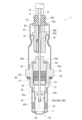
- FIG. 2 is a cross-sectional view of the gas sensor taken along the axial direction.
- FIG. 2 is an exploded perspective view showing a schematic diagram of a detection element portion and a heater portion that constitute a sensor element.
- FIG. 2 is a diagram showing a cross-sectional SEM image including a first lead portion of Example 1.
- FIG. 13 is a diagram showing a cross-sectional SEM image including a first lead portion of Comparative Example 1.
- Fig. 1 is a cross-sectional view of the gas sensor 1 cut along the axis L
- Fig. 2 is an exploded perspective view that typically illustrates a detection element portion 300 and a heater portion 200 that constitute the sensor element 100.
- the lower side of the gas sensor 1 shown in Fig. 1 is referred to as the "front end side,” and the opposite side (the upper side in Fig. 1) is referred to as the "rear end side.”
- the gas sensor 1 comprises a sensor element 100 consisting of a laminate of a detection element section 300 and a heater section 200, a metal shell 30 that holds the sensor element 100 etc. in a manner that accommodates it inside, and a protector 24 that is attached to the tip of the metal shell 30.
- the sensor element 100 is generally in the form of an elongated plate, and is arranged so that its longitudinal direction is aligned with the direction of the axis L.
- a porous protective layer 20 is formed on the tip side of the sensor element 100.
- the heater section 200 is generally in the shape of a long, thin plate, and includes a first base 101 and a second base 103, which are mainly made of alumina, and a heating element 102, which is sandwiched between the first base 101 and the second base 103 and is mainly made of platinum.
- the heating element 102 has a heating portion 102a located at the tip side, and a pair of heater lead portions 102b extending from the heating portion 102a along the longitudinal direction (axis L direction) of the first base 101.
- the ends of the heater lead portions 102b are electrically connected to the heater side pads 120 via conductors formed in heater side through holes 101a provided in the first base 101.
- the detection element section 300 like the heater section 200 , has an elongated plate shape overall, and includes an oxygen concentration detection cell 130 and an oxygen pump cell 140 .
- the oxygen concentration detection cell 130 is composed of a first solid electrolyte body 105, and a first electrode 104 and a second electrode 106 formed on both sides of the first solid electrolyte body 105.
- the first electrode 104 is composed of a first electrode portion 104a and a first lead portion 104b extending from the first electrode portion 104a along the longitudinal direction (axis L direction) of the first solid electrolyte body 105.
- the second electrode 106 is composed of a second electrode portion 106a and a second lead portion 106b extending from the second electrode portion 106a along the longitudinal direction (axis L direction) of the first solid electrolyte body 105.
- the end of the first lead portion 104b is electrically connected to the detection element side pad 121 via conductors formed in the first through hole 105a provided in the first solid electrolyte body 105, the second through hole 107a provided in the insulating layer 107 described later, the fourth through hole 109a provided in the second solid electrolyte body 109, and the sixth through hole 111a provided in the protective layer 111.
- the end of the second lead portion 106b is electrically connected to the detection element side pad 121 via conductors formed in the third through hole 107b provided in the insulating layer 107 described later, the fifth through hole 109b provided in the second solid electrolyte body 109, and the seventh through hole 111b provided in the protective layer 111.
- the first electrode portion 104a and the second electrode portion 106a correspond to a "pair of electrodes" in the claims, and the first lead portion 104b corresponds to "one lead (internal lead)" in the claims.
- the first through hole 105a, the second through hole 107a, the fourth through hole 109a and the sixth through hole 111a correspond to the "communicating holes" in the claims.
- the oxygen pump cell 140 is composed of a second solid electrolyte body 109, and a third electrode 108 and a fourth electrode 110 formed on both sides of the second solid electrolyte body 109.
- the third electrode 108 is composed of a third electrode portion 108a and a third lead portion 108b extending from the third electrode portion 108a along the longitudinal direction (axis L direction) of the second solid electrolyte body 109.
- the fourth electrode 110 is composed of a fourth electrode portion 110a and a fourth lead portion 110b extending from the fourth electrode portion 110a along the longitudinal direction (axis L direction) of the second solid electrolyte body 109.
- the end of the third lead portion 108b is electrically connected to the detection element side pad 121 via a conductor formed in the fifth through hole 109b provided in the second solid electrolyte body 109 and the seventh through hole 111b provided in the protective layer 111.
- the end of the fourth lead portion 110b is electrically connected to the detection element side pad 121 via a conductor formed in the eighth through hole 111c provided in the protective layer 111.
- the second lead portion 106b and the third lead portion 108b are at the same potential.
- the first solid electrolyte body 105 and the second solid electrolyte body 109 are made of a partially stabilized zirconia sintered body obtained by adding yttria (Y 2 O 3 ) or calcia (CaO) as a stabilizer to zirconia (ZrO 2 ).
- the heating element 102, the first electrode 104, the second electrode 106, the third electrode 108, the fourth electrode 110, the heater side pad 120, and the detection element side pad 121 can be formed of a platinum group element. Suitable platinum group elements for forming these include Pt, Rh, Pd, etc. These platinum group elements may be used alone or in combination of two or more kinds.
- the heating elements 102, etc. are preferably formed mainly from Pt from the viewpoint of heat resistance and oxidation resistance.
- the heating elements 102, etc. also preferably contain a ceramic component in addition to the platinum group element that is the main component. From the viewpoint of adhesion, this ceramic component is preferably the same component as the main material on the laminated side.
- An insulating layer 107 is formed between the oxygen pump cell 140 and the oxygen concentration detection cell 130.
- the insulating layer 107 is composed of an insulating portion 114 and a diffusion resistance portion 115.
- a hollow measurement chamber 107c is formed in the insulating portion 114 of the insulating layer 107 at a position corresponding to the second electrode portion 106a and the third electrode portion 108a.
- the measurement chamber 107c communicates with the outside in the width direction of the insulating layer 107, and a diffusion resistance portion 115 that realizes gas diffusion between the outside and the measurement chamber 107c under a predetermined rate-limiting condition is disposed in the communicating portion.
- the insulating portion 114 is not limited as long as it is a ceramic sintered body having insulating properties, and may be made of, for example, an oxide-based ceramic such as alumina or mullite.
- the diffusion resistance portion 115 is a porous body made of alumina, and the speed at which the detection gas flows into the measurement chamber 107c is adjusted by the diffusion resistance portion 115 made of this porous body.
- a protective layer 111 is formed on the surface of the second solid electrolyte body 109 so as to sandwich the fourth electrode 110.
- This protective layer 111 is composed of a porous electrode protective portion 113a for protecting the fourth electrode portion 110a from poisoning by sandwiching the fourth electrode portion 110a, and a reinforcing portion 112 for protecting the second solid electrolyte body 109 by sandwiching the fourth lead portion 110b.
- the sensor element 100 of this embodiment is an oxygen sensor element in which the direction and magnitude of the current flowing between the electrodes of the oxygen pump cell 140 are adjusted so that the voltage (electromotive force) generated between the electrodes of the oxygen concentration detection cell 130 is a predetermined value (for example, 450 mV), and the oxygen concentration in the measured gas is linearly detected according to the current flowing through the oxygen pump cell 140.
- a predetermined value for example, 450 mV
- the cross section of the sensor element 100 When the cross section of the sensor element 100 is viewed perpendicular to the axis L, the cross section is rectangular, with the outer edge consisting of the protective layer 111 and the first substrate 101 forming the long side and the two sides along the stacking direction forming the short sides.
- the metal shell 30 is made of SUS430 and has a male thread portion 31 for mounting the gas sensor 1 to an exhaust pipe, and a hexagonal portion 32 to which an installation tool is applied during installation.
- the metal shell 30 is also provided with a metal side step portion 33 that protrudes radially inward, and the metal side step portion 33 supports a metal holder 34 for holding the sensor element 100.
- a ceramic holder 35 and talc 36 are arranged in this order from the tip side.
- the talc 36 is composed of a first talc 37 disposed within the metal holder 34 and a second talc 38 disposed at the rear end of the metal holder 34.
- the first talc 37 is compressed and filled within the metal holder 34, thereby fixing the sensor element 100 to the metal holder 34.
- the second talc 38 is compressed and filled within the metallic shell 30, thereby ensuring sealing between the outer surface of the sensor element 100 and the inner surface of the metallic shell 30.
- An alumina sleeve 39 is disposed on the rear end side of the second talc 38.
- This sleeve 39 is formed in a multi-stage cylindrical shape, and has an axial hole 39a formed along the axis L.
- the sensor element 100 is inserted into the inside of the sleeve 39, including the axial hole 39a.
- the crimped portion 30a on the rear end side of the metal shell 30 is bent inward, and the sleeve 39 is pressed against the front end side of the metal shell 30 via a stainless steel ring member 40 by the crimped portion 30a.
- a metal protector 24 is attached by welding to the outer periphery of the tip side of the metal shell 30.
- the protector 24 has a double structure, with a cylindrical outer protector 41 with a uniform outer diameter on the outside and a cylindrical inner protector 42 with a rear end 42a with a larger outer diameter than the tip 42b on the inside.
- This protector 24 covers the tip of the sensor element 100 protruding from the tip of the metal shell 30 and has multiple gas intake holes 24a.
- the tip side of an outer tube 25 made of SUS430 is inserted into the rear end side of the metal shell 30.
- the outer tube 25 has a tip portion 25a with an expanded diameter at the tip side, and the tip portion 25a is fixed to the metal shell 30 by laser welding or the like.
- a separator 50 is disposed inside the rear end side of the outer tube 25, and a retaining member 51 is interposed in the gap formed between the separator 50 and the outer tube 25.
- the retaining member 51 is fixed between the crimped outer tube 25 and the separator 50 while engaging with a protruding portion 50a that rises outward from the peripheral surface of the separator 50.
- the separator 50 also has an insertion hole 50b that penetrates from the front end to the rear end for inserting various lead wires 11, 12, 13 for the detection element section 300 and the heater section 200.
- the insertion hole 50b accommodates a connection terminal 16 that connects the lead wires 11, etc. to the detection element side pad 121 of the detection element section 300 and the heater side pad 120 of the heater section 200.
- Each lead wire 11, etc. is configured to be connectable to a connector (not shown) on the outside, and electrical signals are input and output between an external device such as an ECU and each lead wire 11, etc. via such a connector.
- a roughly cylindrical rubber cap 52 is disposed on the rear end side of the separator 50 to close the opening 25b on the rear end side of the outer tube 25.
- This rubber cap 52 is secured to the outer tube 25 by crimping the outer tube 25 radially inward while housed within the rear end of the outer tube 25.
- the rubber cap 52 also has insertion holes 52a that run from the front end side to the rear end side for inserting the lead wires 11, etc.
- the first lead portion 104b which is a characteristic feature of the present invention, will be described.
- the first lead portion 104b is made of a gas-permeable porous body including pores, and communicates with the outside through communication holes (the first through-hole 105a, the second through-hole 107a, the fourth through-hole 109a, and the sixth through-hole 111a) provided in the sensor element 100.
- the detection element side pad 121 electrically connected to the sixth through-hole 111a is also made of a gas-permeable porous body.
- the reference gas generated in the first electrode portion is discharged to the outside via the first lead portion 104b and the communication hole.
- the first lead portion 104b will absorb the water that has entered through the communication hole, and when the sensor element 100 is subsequently heated, the water will vaporize and expand inside the first lead portion 104b, which may damage or break the first lead portion 104b.
- the first lead portion 104b is composed of one or more types of precious metal particles selected from the group consisting of Pt, Pd, Rh, and Au, ceramic particles, and pores, has a porosity greater than 0% and less than or equal to 11%, and the ratio RA of the total area of large pores having a cross-sectional area of 5 ⁇ m2 or more to the total area of pores in the cross section is 8% or more.
- the reason why the porosity of the first lead portion 104b is greater than 0% is that if the first lead portion 104b does not have pores, it becomes gas impermeable and the pressure of the reference gas in the first electrode portion 104a cannot be adjusted. On the other hand, the higher the porosity of the first lead portion 104b, the easier it is for gas to pass through. However, if the porosity exceeds 11%, the conductive precious metal particles in the first lead portion 104b are broken down by the pores, making it more likely to break.
- the porosity is preferably 5% or more, and more preferably 8% or more.
- the ratio RA of the total area of large pores having a cross-sectional area of 5 ⁇ m2 or more to the total area of pores in the cross section is 8% or more, so that water absorbed in the first lead portion 104b can easily escape from these large pores toward the communicating holes.
- the ratio RA is less than 60%. If the ratio RA is 60% or more, there is a risk that the first lead portion 104b will peel off.
- the RA is more preferably 40% or less, further preferably 30% or less, and most preferably 21.6% or less. Furthermore, RA is preferably 10% or more, more preferably 15% or more, and most preferably 20% or more.
- the range of RA is, for example, preferably 10 to 40%, more preferably 15 to 30%, and most preferably 20 to 21.6%.
- the porosity of the first lead portion 104b is measured based on a cross-sectional SEM image including the first lead portion 104b as shown in Fig. 3.
- Fig. 3 is a cross-sectional SEM image of an example described later.
- the cross-sectional SEM image is binarized to extract the pores 104V, which are voids (binarization software: ImageJ), and the area of each pore and the number of pores per area are calculated using the Analyze Particle command.
- the pores 104V are the darkest parts in the cross-sectional SEM image, and the noble metal particles 104M constituting the first lead portion 104b are the brightest parts.
- the ceramic particles 104S constituting the first lead portion 104b are of intermediate brightness.
- parallel lines BL are drawn from the ends of the pores 104V that are connected to the precious metal particles 104M and that are located on the outermost side in the thickness direction of the first lead portion 104b (the vertical direction in FIG. 3) to the surface direction of the first lead portion 104b (the horizontal direction in FIG. 3).
- the parallel lines BL are drawn on both the upper and lower sides of the first lead portion 104b.
- the area of the cross-sectional SEM image surrounded by the two parallel lines BL is regarded as the cross-sectional area of the first lead portion 104b, and the porosity is calculated from the total area of the pores 104V.
- pores 104V that are not connected to the precious metal particles 104M are considered to be voids (cavities) inside other layers adjacent to the first lead portion 104b, and are therefore excluded. Furthermore, when another precious metal particle 104M is located on the outermost side in the thickness direction relative to a pore 104V connected to the other precious metal particle 104M, the position of that precious metal particle 104M is taken as the parallel line BL.
- the total area of the large pores having a cross-sectional area of 5 ⁇ m2 or more in the cross section of the first lead portion 104b is calculated by creating a histogram from the number of pores per area of each pore 104V obtained by image analysis as described above. Then, the ratio RA of the total area of the large pores is calculated from the total area of the pores obtained by image analysis as described above.
- the gas sensor is not limited to an oxygen sensor, but may be, for example, a NOx sensor.
- a plurality of sensor elements 100 shown in FIGS. 1 and 2 were manufactured with the porosity of the first lead portion 104 being varied in various ways.
- Each of the obtained sensor elements 100 was immersed in water to allow the water to penetrate into the first lead portion 104, and then dried.
- the heater portion 200 of the sensor element 100 was driven to heat it to a predetermined temperature, and a characteristic inspection was performed to measure the puncture (disconnection) rate of the first lead portion 104.
- the puncture (disconnection) rate indicates the rate at which the lead is damaged or disconnected.
- Example 1 in which the porosity was 11% or less and the ratio RA of the total area of the large pores was 8% or more, the puncture (breakage) rate was 0%, and damage and breakage of the leads was suppressed.
- Comparative Examples 1 and 2 in which the porosity was 11% or less but the ratio RA of the total area of the large pores was less than 8%, the puncture (disconnection) rate was 100%, and the leads were damaged and disconnected.
- Comparative Example 3 in which the ratio RA of the total area of the large pores was 8% or more but the porosity exceeded 11%, the puncture (disconnection) rate was high and the leads were damaged and disconnected.
- Figures 3 and 4 are cross-sectional SEM images including the first lead portion 104 of Example 1 and Comparative Example 1, respectively, and it can be seen that the cross-sectional area of each pore 104V is smaller in Comparative Example 1, making it difficult for absorbed water to escape.
Landscapes
- Chemical & Material Sciences (AREA)
- Life Sciences & Earth Sciences (AREA)
- Health & Medical Sciences (AREA)
- Physics & Mathematics (AREA)
- Chemical Kinetics & Catalysis (AREA)
- Electrochemistry (AREA)
- Molecular Biology (AREA)
- Analytical Chemistry (AREA)
- Biochemistry (AREA)
- General Health & Medical Sciences (AREA)
- General Physics & Mathematics (AREA)
- Immunology (AREA)
- Pathology (AREA)
- Measuring Oxygen Concentration In Cells (AREA)
Abstract
Description
検知部は1対の電極と固体電解質体とで構成されており、各電極から後端側に向かってリードが延びている。ここで、基準電極に接続される基準リード部には、内部に空孔が形成され、基準リード部を介して素子内外のガスが連通できる構造とすることで、基準電極周囲の基準ガスの圧力を調整するものがある。
そして、大径気孔の合計面積の割合RAが8%以上であるので、この大径気孔から内部リードに吸収された水が連通孔へ向かって抜けやすくなる。その結果、センサ素子に水が侵入後に加熱されたときに、内部リードの内部で水が気化、膨張して内部リードが破損、断線することを抑制できる。
このセンサ素子によれば、内部リードの剥離を抑制できる。
先ず、本実施形態に係るセンサ素子100を含むガスセンサ(酸素センサ)1の構成について説明する。図1は、軸線L方向に沿って切断されたガスセンサ1の断面図、図2は、センサ素子100を構成する検出素子部300及びヒータ部200を模式的に表した分解斜視図である。なお、本明細書では、図1に示されるガスセンサ1の下側を、「先端側」と称し、その反対側(図1の上側)を、「後端側」と称する。
酸素濃度検出セル130は、第1固体電解質体105と、その第1固体電解質体105の両面に形成された第1電極104及び第2電極106とから構成されている。第1電極104は、第1電極部104aと、その第1電極部104aから第1固体電解質体105の長手方向(軸線L方向)に沿って延びる第1リード部104bとから構成されている。第2電極106は、第2電極部106aと、その第2電極部106aから第1固体電解質体105の長手方向(軸線L方向)に沿って延びる第2リード部106bとから構成されている。
また、第1スルーホール105a、第2スルーホール107a、第4スルーホール109a及び第6スルーホール111aが特許請求の範囲の「連通孔」に相当する。
発熱体102、第1電極104、第2電極106、第3電極108、第4電極110、ヒータ側パッド120及び検出素子側パッド121は、白金族元素で形成することができる。これらを形成する好適な白金族元素としては、Pt、Rh、Pd等が挙げられる。なお、これらの白金族元素は、単独で又は2種以上を組み合わせて用いてもよい。
絶縁部114は、絶縁性を有するセラミック焼結体であれば限定されず、例えば、アルミナやムライト等の酸化物系セラミック等から構成される。
拡散抵抗部115は、アルミナからなる多孔質体であり、この多孔質体からなる拡散抵抗部115によって、検出ガスが測定室107cへ流入する際の速度が調整される。
この滑石36は、金属ホルダ34内に配置される第1滑石37と、金属ホルダ34の後端に配置される第2滑石38とからなる。金属ホルダ34内で第1滑石37が圧縮充填されることによって、センサ素子100は金属ホルダ34に対して固定される。また、主体金具30内で第2滑石38が圧縮充填されることによって、センサ素子100の外面と主体金具30の内面との間のシール性が確保される。
第1リード部104bは気孔を含むガス透過性の多孔質体からなり、センサ素子100に設けられた連通孔(第1スルーホール105a、第2スルーホール107a、第4スルーホール109a及び第6スルーホール111a)に臨んで外部と連通している。第6スルーホール111aに電気的に接続される検出素子側パッド121もガス透過性の多孔質体からなる。
そして、第1電極部で生成された基準ガスは、第1リード部104b、連通孔を経由して外部に排出されるようになっている。
一方、第1リード部104bの気孔率が高い方がガスを透過し易くなるが、気孔率が11%を超えると、第1リード部104b中の導電体である貴金属粒子が気孔で分断されて断線し易くなる。
気孔率が5%以上が好ましく、8%以上がより好ましい。
その結果、センサ素子100内部に水が浸入後に加熱されたときに、第1リード部104b内部で水が気化、膨張して第1リード部104bが破損、断線することを抑制できる。
上記割合RAが60%未満であると好ましい。割合RAが60%以上であると、第1リード部104bが剥離するおそれがある。
また、RAが10%以上が好ましく、15%以上がより好ましく、20%以上が最も好ましい。
RAの範囲としては、例えば、10~40%が好ましく、15~30%がさらに好ましく、20~21.6%が最も好ましい。
まず、断面SEM像を二値化して空孔部分である気孔104Vを抽出し(二値化ソフトウェア:ImageJ)、Analyze Particleコマンドから個々の気孔の面積及び面積ごとの個数を算出する。
気孔104Vは断面SEM像の中で最も暗部であり、第1リード部104bを構成する貴金属粒子104Mが最も明部である。また、第1リード部104bを構成するセラミック粒子104Sは中間の明度である。
そして、2つの平行線BLで囲まれた断面SEM像の領域を第1リード部104bの断面積とみなし、気孔104Vの合計面積から、気孔率を算出する。
また、貴金属粒子104Mに繋がる気孔104Vよりも、他の貴金属粒子104Mが厚み方向に最も外側に位置する場合は、その貴金属粒子104Mの位置を平行線BLとする。
ガスセンサとしては、酸素センサに限らず、例えばNOxセンサでもよい。
得られた各センサ素子100を水に浸して第1リード部104内部に水を侵入させ、その後乾燥させた。次に、センサ素子100のヒータ部200を駆動して所定温度に昇温し、特性検査により、第1リード部104のパンク(断線)率を測定した。パンク(断線)率は、リードが破損、断線する割合を示す。
得られた結果を表1、図3、図4に示す。

一方、気孔率が11%以下であるが、大径気孔の合計面積の割合RAが8%未満の比較例1、2の場合、パンク(断線)率が100%であり、リードが破損、断線した。
また、大径気孔の合計面積の割合RAが8%以上であるが、気孔率が11%を超えた比較例3の場合も、パンク(断線)率が高く、リードが破損、断線した。
30 主体金具
100 センサ素子
104a 第1電極部(1対の電極)
104b 第1リード部(一方のリード(内部リード))
104M 貴金属粒子
104S セラミック粒子
104V 気孔
105a 第1スルーホール(連通孔)
106a 第2電極部(1対の電極)
106b 第2リード部(1対のリード)
107a 第2スルーホール(連通孔)
109a 第4スルーホール(連通孔)
111a 第6スルーホール(連通孔)
Claims (3)
- 1対の電極と、
前記1対の電極にそれぞれ接続される1対のリードと、を備えたセンサ素子であって、
前記1対のリードの一方は前記センサ素子の内部に配置される内部リードであるとともに、自身の一部が前記センサ素子に設けられた連通孔に臨んで外部と連通し、
前記内部リードは、Pt、Pd、Rh及びAuの群から選ばれる1種以上の貴金属粒子と、セラミック粒子と、気孔とを含んで構成され、
前記内部リードの気孔率が0%より大きく、11%以下であり、
前記内部リードの断面における前記気孔の合計面積に対し、断面積が5μm2以上の大径気孔の合計面積の割合RAが8%以上を占めることを特徴とするセンサ素子。 - 前記割合RAが60%未満であることを特徴とする請求項1に記載のセンサ素子。
- 請求項1又は2に記載のセンサ素子と、
前記センサ素子を保持する主体金具と、
を有することを特徴とするガスセンサ。
Priority Applications (3)
| Application Number | Priority Date | Filing Date | Title |
|---|---|---|---|
| CN202380076796.6A CN120153251A (zh) | 2023-01-12 | 2023-12-25 | 传感器元件及气体传感器 |
| JP2024570135A JP7829070B2 (ja) | 2023-01-12 | 2023-12-25 | センサ素子及びガスセンサ |
| DE112023005550.5T DE112023005550T5 (de) | 2023-01-12 | 2023-12-25 | Sensorelement und Gassensor |
Applications Claiming Priority (2)
| Application Number | Priority Date | Filing Date | Title |
|---|---|---|---|
| JP2023-002951 | 2023-01-12 | ||
| JP2023002951 | 2023-01-12 |
Publications (1)
| Publication Number | Publication Date |
|---|---|
| WO2024150656A1 true WO2024150656A1 (ja) | 2024-07-18 |
Family
ID=91896935
Family Applications (1)
| Application Number | Title | Priority Date | Filing Date |
|---|---|---|---|
| PCT/JP2023/046372 Ceased WO2024150656A1 (ja) | 2023-01-12 | 2023-12-25 | センサ素子及びガスセンサ |
Country Status (4)
| Country | Link |
|---|---|
| JP (1) | JP7829070B2 (ja) |
| CN (1) | CN120153251A (ja) |
| DE (1) | DE112023005550T5 (ja) |
| WO (1) | WO2024150656A1 (ja) |
Citations (4)
| Publication number | Priority date | Publication date | Assignee | Title |
|---|---|---|---|---|
| JP2011117937A (ja) * | 2009-11-02 | 2011-06-16 | Ngk Spark Plug Co Ltd | ガスセンサ |
| JP2019027847A (ja) * | 2017-07-27 | 2019-02-21 | 日本特殊陶業株式会社 | ガスセンサ |
| JP2019148545A (ja) * | 2018-02-28 | 2019-09-05 | 日本特殊陶業株式会社 | ガスセンサ |
| JP2021156786A (ja) * | 2020-03-27 | 2021-10-07 | 日本碍子株式会社 | センサ素子及びガスセンサ |
-
2023
- 2023-12-25 JP JP2024570135A patent/JP7829070B2/ja active Active
- 2023-12-25 WO PCT/JP2023/046372 patent/WO2024150656A1/ja not_active Ceased
- 2023-12-25 DE DE112023005550.5T patent/DE112023005550T5/de active Pending
- 2023-12-25 CN CN202380076796.6A patent/CN120153251A/zh active Pending
Patent Citations (4)
| Publication number | Priority date | Publication date | Assignee | Title |
|---|---|---|---|---|
| JP2011117937A (ja) * | 2009-11-02 | 2011-06-16 | Ngk Spark Plug Co Ltd | ガスセンサ |
| JP2019027847A (ja) * | 2017-07-27 | 2019-02-21 | 日本特殊陶業株式会社 | ガスセンサ |
| JP2019148545A (ja) * | 2018-02-28 | 2019-09-05 | 日本特殊陶業株式会社 | ガスセンサ |
| JP2021156786A (ja) * | 2020-03-27 | 2021-10-07 | 日本碍子株式会社 | センサ素子及びガスセンサ |
Also Published As
| Publication number | Publication date |
|---|---|
| DE112023005550T5 (de) | 2025-11-27 |
| CN120153251A (zh) | 2025-06-13 |
| JP7829070B2 (ja) | 2026-03-12 |
| JPWO2024150656A1 (ja) | 2024-07-18 |
Similar Documents
| Publication | Publication Date | Title |
|---|---|---|
| JP5390682B1 (ja) | ガスセンサ素子及びガスセンサ | |
| US8992752B2 (en) | Gas sensor element and gas sensor | |
| EP2818855B1 (en) | Gas sensor element and gas sensor | |
| CN103998922B (zh) | 气体传感器用电极及气体传感器 | |
| JP5373837B2 (ja) | ガスセンサ素子及びガスセンサ | |
| US9829462B2 (en) | Gas sensor element and gas sensor | |
| JP4578556B2 (ja) | ガスセンサ及びその製造方法 | |
| US8377273B2 (en) | Gas sensor | |
| US8623188B2 (en) | Gas sensor | |
| JP6859227B2 (ja) | ガスセンサ | |
| US10876991B2 (en) | Gas sensor | |
| US20070084724A1 (en) | Gas sensing device and gas sensor | |
| JP4965356B2 (ja) | ガスセンサの劣化判定方法 | |
| CN109425645B (zh) | 气体传感器元件以及气体传感器 | |
| WO2024150656A1 (ja) | センサ素子及びガスセンサ | |
| JP5115247B2 (ja) | ガスセンサ素子 | |
| US20240241076A1 (en) | Sensor element and gas sensor | |
| JP7669567B2 (ja) | ガスセンサ | |
| US12031937B2 (en) | Sensor element, gas sensor, and method for manufacturing sensor element | |
| JP2026032593A (ja) | センサ素子及びガスセンサ | |
| JP2025072715A (ja) | センサ素子及びガスセンサ |
Legal Events
| Date | Code | Title | Description |
|---|---|---|---|
| 121 | Ep: the epo has been informed by wipo that ep was designated in this application |
Ref document number: 23916270 Country of ref document: EP Kind code of ref document: A1 |
|
| WWE | Wipo information: entry into national phase |
Ref document number: 2024570135 Country of ref document: JP |
|
| WWE | Wipo information: entry into national phase |
Ref document number: 202380076796.6 Country of ref document: CN |
|
| WWP | Wipo information: published in national office |
Ref document number: 202380076796.6 Country of ref document: CN |
|
| WWE | Wipo information: entry into national phase |
Ref document number: 112023005550 Country of ref document: DE |
|
| WWP | Wipo information: published in national office |
Ref document number: 112023005550 Country of ref document: DE |
|
| 122 | Ep: pct application non-entry in european phase |
Ref document number: 23916270 Country of ref document: EP Kind code of ref document: A1 |