WO2024150620A1 - 揺動アクチュエータ - Google Patents
揺動アクチュエータ Download PDFInfo
- Publication number
- WO2024150620A1 WO2024150620A1 PCT/JP2023/045523 JP2023045523W WO2024150620A1 WO 2024150620 A1 WO2024150620 A1 WO 2024150620A1 JP 2023045523 W JP2023045523 W JP 2023045523W WO 2024150620 A1 WO2024150620 A1 WO 2024150620A1
- Authority
- WO
- WIPO (PCT)
- Prior art keywords
- magnet
- magnetic
- coil
- gap
- disposed
- Prior art date
- Legal status (The legal status is an assumption and is not a legal conclusion. Google has not performed a legal analysis and makes no representation as to the accuracy of the status listed.)
- Ceased
Links
Images





Classifications
-
- G—PHYSICS
- G02—OPTICS
- G02B—OPTICAL ELEMENTS, SYSTEMS OR APPARATUS
- G02B26/00—Optical devices or arrangements for the control of light using movable or deformable optical elements
- G02B26/08—Optical devices or arrangements for the control of light using movable or deformable optical elements for controlling the direction of light
-
- G—PHYSICS
- G02—OPTICS
- G02B—OPTICAL ELEMENTS, SYSTEMS OR APPARATUS
- G02B26/00—Optical devices or arrangements for the control of light using movable or deformable optical elements
- G02B26/08—Optical devices or arrangements for the control of light using movable or deformable optical elements for controlling the direction of light
- G02B26/10—Scanning systems
-
- H—ELECTRICITY
- H02—GENERATION; CONVERSION OR DISTRIBUTION OF ELECTRIC POWER
- H02K—DYNAMO-ELECTRIC MACHINES
- H02K33/00—Motors with reciprocating, oscillating or vibrating magnet, armature or coil system
- H02K33/18—Motors with reciprocating, oscillating or vibrating magnet, armature or coil system with coil systems moving upon intermittent or reversed energisation thereof by interaction with a fixed field system, e.g. permanent magnets
Definitions
- the present invention relates to an oscillating actuator.
- oscillating actuators Conventionally, reciprocating rotary drive, or oscillating actuators (hereafter referred to as “oscillating actuators”) have been known as actuators used in scanner devices such as multifunction machines, laser beam printers, laser processing machines, and laser markers. Laser processing machines perform laser drilling of printed circuit boards, etc.
- the oscillating actuator for example, comprises a rotating shaft to which a mirror is attached and a drive unit having a coil magnet. By passing electricity through the coil and driving the rotating shaft to rotate back and forth, the angle at which the laser light is reflected by the mirror is changed, thereby achieving optical scanning of the target object.
- a mirror and coil are attached to a horizontally extending rotation axis, and a pair of magnets, with their south and north poles facing each other with a gap between them, is provided on the fixed part.
- Each of the two sides of the coil that are parallel to the direction of the rotation axis are configured to be positioned in the gap between the south and north poles of the magnet pair, and a total of four magnets are provided on the fixed part, and the mirror oscillates when electricity is passed through the coil.
- the pairs of magnets that sandwich the left and right sides of the coil are arranged so that the magnetic poles attract each other on the opposing surfaces.
- the opposing magnets attract each other and stick together, making it difficult to assemble properly and making the assembly process time-consuming.
- the object of the present invention is to provide an oscillating actuator that can be easily assembled with high precision even when there is a gap between the magnets.
- the rocking actuator of the present invention comprises: a fixed portion having three or more magnets arranged such that different magnetic poles face each other with a gap therebetween; a movable part having a coil with one side portion disposed in the gap and being rotatable back and forth about an axis parallel to the one side portion relative to the fixed part; having The magnet includes a first magnet disposed inside the coil and a second magnet disposed outside the coil, The second magnet is configured such that a surface of the second magnet opposite to a surface of the magnetic pole facing the first magnet is connected to a magnetic member.
- magnets can be easily assembled with high precision even when there are gaps between them.
- 1 is a perspective view of a rocking actuator according to an embodiment of the present invention
- 1 is a plan view of a rocking actuator according to an embodiment of the present invention
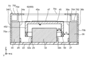
- 3 is a cross-sectional view taken along line AA in FIG. 2.
- 3 is a cross-sectional view taken along line BB in FIG. 2.
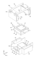
- 1 is a diagram showing a state in which a fixed part and a movable part of a rocking actuator according to an embodiment of the present invention are separated.
- 1 is an exploded perspective view of a rocking actuator according to an embodiment of the present invention
- 1 is a side cross-sectional view showing a magnetic circuit of a rocking actuator according to an embodiment of the present invention.
- the components constituting the oscillating actuator 1 of this embodiment will be described based on the normal state in which the oscillating actuator 1 is not driven and is in a non-operating state.
- a Cartesian coordinate system (X, Y, Z) is used to explain the structure of the oscillating actuator 1 of this embodiment.
- the same Cartesian coordinate system (X, Y, Z) is also used in the figures described later.
- FIG. 1 is a perspective view of an oscillating actuator according to an embodiment of the present invention
- FIG. 2 is a plan view of the oscillating actuator according to an embodiment of the present invention
- FIG. 3 and FIG. 4 are cross-sectional views taken along lines A-A and B-B in FIG. 2, respectively.
- FIG. 5 is an exploded perspective view showing the fixed and movable parts of the oscillating actuator according to an embodiment of the present invention
- FIG. 6 is an overall exploded perspective view of the oscillating actuator according to an embodiment of the present invention.
- the oscillating actuator 1 is used, for example, in optical scanning devices such as laser processing machines, multifunction machines, and laser beam printers, or in LiDAR (Laser Imaging Detection and Ranging) devices.
- optical scanning devices such as laser processing machines, multifunction machines, and laser beam printers
- LiDAR Laser Imaging Detection and Ranging
- the oscillating actuator 1 has a movable part 40, a fixed part 10, and an elastic support part 60 that supports the movable part 40 so that it can move freely relative to the fixed part 10.
- the oscillating actuator 1 drives the movable part 40 itself or a movable object connected to the movable part 40 (e.g., a mirror 47) to rotate back and forth around one axis, i.e., oscillate, relative to the fixed part 10.
- the oscillating actuator 1 drives the movable part 40 through cooperation between the magnet part 30 and the energized coil 50.
- the fixed part base 20 has a rectangular plate-shaped base part 22, support walls 23 and 24, a first restricting part 25, a second restricting part 26, and a third restricting part 27.
- the base portion 22 is formed in a rectangular plate shape, and the first magnet 32, second magnet 34, and third magnet 36 are arranged on the upper surface with a gap between them.
- the first magnet 32, second magnet 34, and third magnet 36 are arranged with their magnetic poles 32a, 32b, 34a, and 36a facing each other.
- the first magnet 32, second magnet 34, and third magnet 36 are arranged facing each other with a gap between them in the direction of attraction.
- wiring for supplying power to the coils may be arranged in the base portion 22 by insert molding.
- the base portion 22 has an arrangement area in which the first magnet 32, the second magnet 34, and the third magnet 36 are respectively arranged, and the arrangement area is partitioned by the first restricting portion 25, the second restricting portion 26, and the third restricting portion 27.
- the first regulating portion 25, the second regulating portion 26, and the third regulating portion 27 are wall portions disposed on the base portion 22 between the first magnet 32, the second magnet 34, and the third magnet 36, respectively.
- the first regulating portion 25, the second regulating portion 26, and the third regulating portion 27 regulate the movement of the first magnet 32, the second magnet 34, and the third magnet 36 in the directions facing each other.
- the first restricting portion 25 is, for example, a frame-shaped wall portion that protrudes in a frame shape from the center of the base portion 22 so as to surround the arrangement position of the first magnet 32 .
- the second regulating portion 26 and the third regulating portion 27 are protruding wall portions erected on the base portion 22 with a gap in the lateral direction (e.g., the X direction) from the first regulating portion 25, sandwiching the first regulating portion 25 from both sides, and are arranged facing each other.
- the fixed part base 20, together with the first magnet 32, the second magnet 34 and the third magnet 36, is covered from above (upper side in the Z direction) by the yoke 70.
- the support walls 23, 24 support the elastic support part 60 above the base part 22, and are arranged on the base part 22 in a direction perpendicular to the arrangement direction of the multiple magnets (32, 34, 36) and on either side of the arrangement position of the first magnet 32.
- the support walls 23, 24 are arranged to protrude upward from a position sandwiching the base 22, and are provided opposite each other.
- An elastic support part 60 is installed between the upper ends of the support walls 23, 24, and the support walls 23, 24 position the elastic support part 60 above the first magnet 32.
- elements of the drive system of the oscillating actuator can be arranged as components (not shown) for connecting externally to supply power, such as wiring (not shown) for supplying power to the coil 50.
- the magnet section 30 has a first magnet 32, a second magnet 34, and a third magnet 36, each of which is a permanent magnet.
- the first magnet 32, the second magnet 34, and the third magnet 36 are arranged with their magnetization directions in the same direction.
- the first magnet 32 has magnetic poles 32a, 32b, which are north and south poles spaced apart in the horizontal direction (Y direction in the figure), that face magnetic poles in other magnets (second magnet 34, third magnet 36) that attract each other due to magnetic attraction force.
- the first magnet 32 has a predetermined length in the direction in which the multiple magnets are arranged, and is formed, for example, in a rectangular parallelepiped shape having a square shape in a plan view.
- the first magnet 32 is disposed in the center of the base portion 22, and is disposed so as to be covered by the movable portion 40.
- the second magnet 34 and the third magnet 36 are arranged facing the first magnet 32 with the magnetic poles 34a, 36a having a larger surface than the magnetic poles 32a, 32b of the first magnet 32.
- the first magnet 32 is arranged so as to be located within the area sandwiched between the magnetic poles 34a, 36a of the second magnet 34 and the third magnet 36.
- the second magnet 34 and the third magnet 36 are rectangular flat plates, and are thinner in the Y direction than the first magnet 32 .
- the second magnet 34 and the third magnet 36 are disposed opposite the first magnet 32 with a gap therebetween and have different magnetic poles. For example, if the magnetic pole 32a of the first magnet 32 is an S pole, the magnetic pole 34a of the second magnet 34 is an S pole, the magnetic pole 32b is an N pole, and the magnetic pole 36a of the third magnet 36 is an S pole.
- the second magnet 34 and the third magnet 36 are formed in the same way, they can be arranged symmetrically with respect to the first magnet 32 with opposite poles facing each other, thereby reducing costs.
- the magnetic poles 34b, 36b on the opposite side to the magnetic poles 34a, 36a facing the first magnet 32 are connected by the side plates 70a, 70b of the yoke 70 in close contact with each other.
- the non-facing surfaces (magnetic poles 34b, 36b) of the magnets which have different magnetic poles (north and south poles) facing each other, are connected to the first magnet 32 by a yoke 70 (side plates 70a, 70b), which is a magnetic member.
- the yoke 70 is a magnetic member that allows magnetic flux to flow and, together with the magnet section 30 and the coil 50 of the movable section 40, constitutes a magnetic circuit of the oscillating actuator 1.
- the yoke 70 also has the function of precisely arranging the multiple magnets 32, 34, 36, which face each other with their mutually attracting surfaces, at a predetermined distance apart in the oscillating actuator 1.
- the yoke 70 is disposed above the base portion 22 and is disposed so as to movably cover the movable portion 40.
- the yoke 70 has side plates 70a, 70b and an upper surface portion 70d that includes an installation arm 70c installed between the side plates 70a, 70b and connects the side plates 70a, 70b.
- the upper surface portion 70d is disposed above the first magnet 32, extending in the direction in which the magnets are arranged, and covering the magnets 32, 34, and 36.
- An opening is provided in the upper surface portion 70d, and the upper surface side of the movable portion 40 is exposed upward through this opening.
- the opening is partitioned into an opening frame in the Y direction by a pair of mounting arms 70c extending in the X direction in which the multiple magnets 32, 34, 36 are lined up.
- the mounting arms 70c extend above the first magnet 32 in the direction in which the multiple magnets 32, 34, 36 are lined up on the upper surface 70d. Both ends of the mounting arms 70c are arranged perpendicular to the side plates 70a, 70b and connected to shoulders that cover the second magnet 34 and the third magnet 36 from above.
- the mounting arms 70c and the upper surface 70d having shoulders (magnetic path forming portions) 70f form the side plates 70a, 70b facing each other with a predetermined gap between them.
- the side plates 70a, 70b hang down from shoulders 70f at both ends of the top surface 70d, and their inner surfaces are connected to the outer magnetic poles 34b, 36b of the second magnet 34 and the third magnet 36.
- the yoke 70 is a magnetic body, and the side plates 70a, 70b are in a state where magnetic flux flows with respect to the second magnet 34 and the third magnet 36.
- the shoulder portion 70f is disposed in a state in which it abuts against the upper ends of the second magnet 34 and the third magnet 36 by the bent portion 76, and at a position spaced above them.
- the bent portion 76 has a contact surface portion 762 that contacts the upper ends of the second magnet 34 and the third magnet 36, respectively, and a separation portion 764 that rises upward from the contact surface portion 762.
- the contact surface portion 762 is in full contact with the second magnet 34 and the third magnet 36, respectively, thereby ensuring a wide contact area with the second magnet 34 and the third magnet 36 as the yoke 70.
- the separation portion 764 separates the upper ends of the second magnet 34 and the third magnet 36 from the upper surface of the shoulder portion 70f (upper surface portion 70d).
- the yoke 70 constitutes a magnetic circuit that passes through the first magnet 32 and connects the second magnet 34 and the third magnet 36.
- the side plates 70a, 70b are in contact with and connected to the second magnet 34 and the third magnet 36 by the magnetic attraction force of the second magnet 34 and the third magnet 36.
- the installation arm 70c is positioned away from the upper ends of the second magnet 34 and the third magnet 36 in order to ensure a movable area for the movable part 40 and to improve the magnetic efficiency of the magnetic flux flowing through the installation arm 70c.
- the improvement of the magnetic efficiency of the magnetic flux is achieved by preventing the flow of magnetic flux through any place other than the intended magnetic circuit when the installation arm 70c is close to the upper end of each of the second magnet 34 and the third magnet 36. Specifically, when the installation arm 70c is positioned close to the upper end of each of the second magnet 34 and the third magnet 36, the magnetic flux may return to the second magnet 34 and the third magnet 36 (see unnecessary magnetic flux flow C in Figure 7).
- the installation arm 70c is disposed away from the upper end of each of the second magnet 34 and the third magnet 36. This prevents the magnetic flux from returning to each of the second magnet 34 and the third magnet 36, prevents loss of the magnetic flux flow, and increases the magnetic efficiency in the magnetic circuit.
- the yoke 70 with its side plates 70a, 70b and top surface 70d (including shoulder 70f and mounting arm 70c), forms a magnetic circuit that contacts the second magnet 34 and the third magnet 36 while connecting the second magnet 34 and the third magnet 36 to each other.
- this magnetic circuit has high magnetic efficiency because the top surface 70d is spaced apart from the second magnet 34 and the third magnet 36.
- the movable part 40 has a coil 50, a movable part main body 45, and a mirror 47 which is an object to be moved.
- the movable part 40 is arranged movably relative to the fixed part 10 with a part of the coil 50 being arranged between the plurality of magnets 32, 34, 36 via an elastic support part 60.
- the coil 50 is disposed so as to surround the first magnet 32 at a distance from it.
- One side (each of a pair of sides here) of the coil 50 is disposed in the gap between the first magnet 32 and the second and third magnets 34 and 36.
- One side (a pair of sides) of the coil 50 is disposed so as to be perpendicular to the direction in which the magnetic poles 32a, 32b, 34a, and 36a face each other, and so that a current flows in the longitudinal direction of each of the magnetic poles 32a, 32b, 34a, and 36a.
- the winding axis of the coil 50 is in the Z direction, and the coil is wound so that the coil wire extends in the X and Y directions, surrounding the first magnet 32.
- the coil 50 is fixed to the movable body 45, and the coil 50 is arranged in a state where it is suspended from the elastic support part 60 via the movable body 45.
- the movable part body 45 is the main body of the movable part 40 and may function as a weight.
- the movable part body 45 is a box-shaped body that is square in plan view and has a hollow part 45a that opens downward, and is positioned so as to cover the first magnet 32 from above.
- the coil 50 is connected to the lower end of the movable body 45, and the peripheral wall portion 452 is arranged to surround the first magnet 32.
- the inner side of the peripheral wall portion 452 faces both side surfaces of the first magnet 32 in the X direction with a predetermined distance (gap G0) between them.
- the outer side of a part of the peripheral wall portion 452 (the upper part of one side of the coil 50) faces the magnetic poles 34a, 36a of the second magnet 34 and the third magnet 36 with a predetermined distance between them.
- the elastic support part 60 supports the movable part 40 so that it can swing, i.e., rotate back and forth, on an axis extending in the Y direction.
- the elastic support part 60 is a leaf spring installed between the support walls 23, 24 of the fixed part base 20.
- the elastic support part 60 may be configured in any manner as long as it supports the movable part 40 so that it can swing on an axis extending in the Y direction.
- the elastic support portion 60 has a fixed frame portion 62 fixed along the outer periphery of the upper surface of the movable portion 40, and deformable arms 64 connecting the fixed frame portion 62 and the support wall portions 23, 24, with two arms 64 provided on each side of the movable portion 40, but this is not limited to this. Any number of arms 64 of the elastic support portion 60 may be connected to the fixed frame portion 62 as long as the movable portion 40 is configured to swing on a single axis extending in the Y direction.
- the arms 64 may be configured, for example, so that one arm protrudes from each of both sides of the fixed frame portion 62 that are spaced apart in the Y direction, or three or more arms protrude from each side, and are fixed to the fixed portion 10 such as the support wall portions 23, 24.
- FIG. 7 is a cross-sectional side view showing the magnetic circuit of an oscillating actuator according to an embodiment of the present invention.
- the magnetic pole 32a is set as a north pole
- the magnetic pole 32b is set as a south pole
- the magnetic pole 34a is set as a south pole
- the magnetic pole 36a is set as a north pole
- a driving current is passed through the coil 50 in a counterclockwise direction, for example.
- an upward (Z-direction) electromagnetic force acts on a part of the coil 50 between the first and second magnets
- a downward (-Z-direction) electromagnetic force acts on a part of the coil 50 between the first and third magnets.
- the electromagnetic force acting on the coil 50 becomes a driving torque
- the movable section 40 rotates.
- the movable section 40 is movably suspended by the arms 64 of the elastic support section 60, the arms 64 arranged symmetrically in the X-direction around one axis are deformed (twisted), and rotate around one axis extending in the Y-axis direction. Also, by reversing the direction of the driving current, the rotation in the opposite direction is performed. By controlling in this way, the movable part 40 can be driven to rotate back and forth (the double-headed arrow in Figure 7 indicates the movable direction of the movable body that rotates back and forth around one axis).
- a number of magnets (first magnet 32, second magnet 34, third magnet 36) are arranged on the base portion 22 with magnetic poles 32a, 32b, 34a, 36a facing each other and attracting each other with a gap therebetween.
- the magnetic circuit is such that magnetic flux flows from the north pole to the south pole in the direction of attraction of each of the multiple magnets 32, 34, and 36.
- the magnetic flux passes through the second magnet 34, the first magnet 32, and the third magnet 36, through the side plate 70b of the yoke 70, through the mounting arm 70c, to the side plate 70a, and finally to the second magnet 34.
- the magnetic flux that leaves the third magnet 36 (or the second magnet 34 if the magnetic flux flows in the opposite direction in the magnetic circuit) shown in FIG. 7 and reaches the installation arm 70c does not return to the third magnet 36, as does the unwanted magnetic flux flow C.
- the magnetic flux can be reliably passed through the second magnet 34 via the installation arm 70c to flow in the magnetic circuit, resulting in a more efficient magnetic circuit.
- the magnetic poles 34a and 36a of the second magnet 34 and the third magnet 36 are arranged to attract each other, facing the magnetic poles 32a and 32b, which are the north and south poles, of the first magnet 32.
- the magnetic poles 34b and 36b on the opposite side to the magnetic poles 34a and 36a that attract the first magnet 32, i.e., the non-facing side are abutted against the side plates 70a and 70b of the yoke 70, which is a magnetic member, and are connected by an attractive force.
- the force of attraction between the second magnet 34 and the third magnet 36 and the first magnet 32 can be dispersed and reduced. This allows the second magnet 34 and the third magnet 36 to be brought closer to the first magnet 32, and the magnets can be positioned with high precision, leaving gaps G0 and G between them, without any problems caused by the force of attraction between the magnets.
- the vibration actuator 1 can be easily assembled with high precision as an oscillating actuator 1 with a good magnetic circuit.
- the second magnet 34 and the third magnet 36 are attached to the yoke 70, and the first magnet 32 is attached to the fixed part base 20 arranged in the installation area of the base part 22.
- the second magnet 34 and the third magnet 36 are fixed to the yoke 70 in a state where they are attracted to each other by the magnetic attraction force of the second magnet 34 and the third magnet 36.
- the second magnet 34 and the third magnet 36 can be arranged close to the first magnet 34 while assembling, and the swing actuator 1 can be easily attached and assembled.
- the oscillating actuator 1 has a fixed part 10 having three or more magnets 32, 34, 36 arranged with different magnetic poles facing each other across gaps G0, G, and a coil 50 with one side located in the gap G0, G.
- the movable part 40 has the coil 50 and is provided so as to be freely rotatable back and forth on an axis parallel to one side of the coil 50 relative to the fixed part 10.
- the magnet section 30 has a first magnet 32 arranged inside the coil 50, and a second magnet 34 arranged outside the coil 50.
- the second magnet 34 is connected to a side plate (magnetic member) 70a on the side opposite the side of the magnetic pole 34a that faces the first magnet 32.
- the magnet section 30 also has a third magnet 36, with a different magnetic pole 36a arranged to face the magnetic pole 32b on the side opposite the magnetic pole 32a that faces the second magnet 34 in the first magnet 32, with a gap G0, G similar to the gap G0, G.
- the third magnet 36 is connected to a side plate (magnetic member) 70b that is continuous with a side plate (magnetic member) 70a that is connected to the second magnet 34, at a magnetic pole 36b on the opposite side to the magnetic pole 36a that faces the first magnet 32.
- the yoke 70 which is a magnetic member, is connected to the upper end of the side plate (planar portion) 70a that is connected at the opposite surface, and has an upper surface portion (magnetic path portion) 70d that is positioned on the upper surface side of the second magnet 34.
- the upper surface portion (magnetic path portion) 70d is disposed with a gap between it and the second magnet 34 and has a shoulder portion (magnetic path forming portion) 70f that forms a magnetic path, and a bent portion (connecting magnetic path portion) 76 that abuts against the upper surface of the second magnet 34 and connects to the shoulder portion 70f.
- the shapes of the first magnet 32, second magnet 34, third magnet 36, fixed part base 20, elastic support part 60, and yoke 70 in the above embodiment are not limited to these, and may be formed in any manner as long as they have their respective functions.
- the mirror 47 which is the movable object, is directly attached to the movable part body 45, but it may be connected to the movable part body 45 via another member as long as it is driven to rotate back and forth around one axis together with the movable part body 45.
- the oscillating actuator 1 is configured to rotate the movable part 40 back and forth around a single axis without a shaft, but it may also be configured to have a shaft and to drive the movable part around a support axis.
- the oscillating actuator 1 is a so-called moving coil actuator in which a magnet part 30 is arranged on the fixed part 10 and a coil 50 is arranged on the movable part 40 side, but it is not limited to this and may also be a moving magnet.
- the oscillating actuator of the present invention is easy to assemble and has the advantage of being able to perform reciprocating rotational drive, making it useful, for example, as an actuator used in scanner devices, etc.
- Swing actuator 10 Fixed portion 20: Fixed portion base 22: Base portion 23, 24: Support wall portion 25: First restricting portion 26: Second restricting portion 27: Third restricting portion 30: Magnet portion 32: First magnet (first magnet) 32a, 32b, 34a, 34b, 36a, 36b Magnetic poles 34 First magnet (second magnet) 36 Third magnet (third magnet) 40 Movable part 45 Movable part main body 47 Mirror 50 Coil 60 Elastic support part 62 Fixed frame part 64 Arm 70 Yoke 70a, 70b Side plate 70c Mounting arm 70d Top surface part 70f Shoulder part (magnetic path forming part) 76 Bending section (connecting magnetic path section) 762 Contact surface portion 764 Separation portion
Landscapes
- Physics & Mathematics (AREA)
- General Physics & Mathematics (AREA)
- Optics & Photonics (AREA)
- Engineering & Computer Science (AREA)
- Power Engineering (AREA)
- Reciprocating, Oscillating Or Vibrating Motors (AREA)
- Mechanical Optical Scanning Systems (AREA)
- Mechanical Light Control Or Optical Switches (AREA)
Abstract
振動アクチュエータは、互いに異なる磁極が間隙を空けて対向するように配置される3つ以上の磁石を有する固定部と、間隙に一辺部が配置されるコイルを有し、固定部に対して一辺部と平行な軸線で往復回自在に設けられる可動部と、を有し、磁石は、コイルの内側に配置される第1磁石と、コイルの外側に配置される第2磁石と、を有し、第2磁石は、第1磁石と対向する磁極の面とは反対側の面で、磁性部材に接続されている。
Description
本発明は、揺動アクチュエータに関する。
従来、複合機、レーザービームプリンタ、レーザー加工機、レーザーマーカー等のスキャナ装置に用いられるアクチュエータとして、往復回転駆動式、つまり揺動式のアクチュエータ(以下、「揺動アクチュエータ」と称する)が知られている。なお、レーザー加工機は、プリント基板のレーザー穴明け加工等である。
揺動アクチュエータは、例えば、ミラーが取り付けられる回転軸と、コイルマグネットを有する駆動部とを備え、コイルに通電して、回転軸を往復回転駆動させることにより、ミラーによるレーザー光の反射角度を変更して、対象物に対する光走査を実現する。
特許文献1に示す揺動アクチュエータでは、水平に延びる回転軸にミラーとコイルが取り付けられ、互いのS極とN極とを間隙を開けて対向配置したマグネット対が固定部に設けられている。コイルにおいて回転軸方向と平行な両側部の夫々は、マグネット対のS極とN極との間隙に夫々位置するように構成され、計4つのマグネットが固定部に設けられコイルに通電することにより、ミラーは揺動する。
ところで、従来の揺動アクチュエータでは、コイルの左右の両側部の夫々を挟むマグネット対は、互いに対向する面で磁極が引き合うように配置されている。これを組み立てる場合、対向配置されるマグネット同士は、互いに引き合いくっついてしまい、巧く組み立てることできず、組み立て作業に手間かがかかるという問題があった。
また、従来の揺動アクチュエータにおいて、駆動力を増加させるためにマグネットを大きくする場合、間隙を空けて配置されるマグネットの引き合う力が大きくなり、精度高く間隙を維持した組立が一層難くなるという問題がある。
本発明の目的は、磁石同士に間隙を有しても、容易に高精度に組み立てることができる揺動アクチュエータを提供することである。
本発明の揺動アクチュエータは、
互いに異なる磁極が間隙を空けて対向するように配置される3つ以上の磁石を有する固定部と、
前記間隙に一辺部が配置されるコイルを有し、前記固定部に対して前記一辺部と平行な軸線で往復回自在に設けられる可動部と、
を有し、
前記磁石は、前記コイルの内側に配置される第1磁石と、前記コイルの外側に配置される第2磁石と、を有し、
前記第2磁石は、前記第1磁石と対向する磁極の面とは反対側の面で、磁性部材に接続されている構成を採る。
互いに異なる磁極が間隙を空けて対向するように配置される3つ以上の磁石を有する固定部と、
前記間隙に一辺部が配置されるコイルを有し、前記固定部に対して前記一辺部と平行な軸線で往復回自在に設けられる可動部と、
を有し、
前記磁石は、前記コイルの内側に配置される第1磁石と、前記コイルの外側に配置される第2磁石と、を有し、
前記第2磁石は、前記第1磁石と対向する磁極の面とは反対側の面で、磁性部材に接続されている構成を採る。
本発明によれば、磁石同士に間隙を有しても、容易に高精度で組み立てることができる。
以下、本発明の実施の形態について、図面を参照して詳細に説明する。
本実施の形態の揺動アクチュエータ1を構成する各部については、揺動アクチュエータ1が駆動しておらず、非動作状態である通常状態時を基準として説明する。また、本実施形態の揺動アクチュエータ1の構造を説明するにあたり、直交座標系(X,Y,Z)を使用する。後述する図においても共通の直交座標系(X,Y,Z)で示している。
図1は、本発明の実施の形態に係る揺動アクチュエータの斜視図であり、図2は、本発明の実施の形態に係る揺動アクチュエータの平面図であり、図3、図4は、夫々、図2のA-A線断面図、B-B線断面図である。また、図5は、本発明の実施の形態に係る揺動アクチュエータの固定部と可動部を示す分解斜視図であり、図6は、本発明の実施の形態に係る揺動アクチュエータの全体分解斜視図である。
揺動アクチュエータ1は、例えば、レーザー加工機、複合機、レーザービームプリンタ等の光走査装置、或いは、ライダー(LiDAR:Laser Imaging Detection and Ranging)装置に用いられる。
揺動アクチュエータ1は、可動部40と、固定部10と、固定部10に対して可動部40を可動自在に支持する弾性支持部60と、を有する。
揺動アクチュエータ1は、固定部10に対して、可動部40自体或いは可動部40に接続される可動対象物(例えば、ミラー47)を、一軸を中心に往復回転駆動、つまり、揺動させる。揺動アクチュエータ1は、マグネット部30と、通電されるコイル50との協働により可動部40を駆動する。
<固定部10>
図1から図6に示すように、固定部10は、固定部基部20と、3つ以上のマグネットを含むマグネット部30と、ヨーク70と、を有する。
図1から図6に示すように、固定部10は、固定部基部20と、3つ以上のマグネットを含むマグネット部30と、ヨーク70と、を有する。
固定部基部20は、矩形板状のベース部22と、支持壁部23、24と、第1規制部25、第2規制部26、第3規制部27とを有する。
ベース部22は、矩形板状に形成され、上面に第1マグネット32、第2マグネット34及び第3マグネット36が夫々間隙を空けて配置されている。ベース部22では、第1マグネット32、第2マグネット34及び第3マグネット36は、互いの磁極32a、32b、34a、36a同士が、互いに対向して配置される。すなわち、ベース部22では、第1マグネット32、第2マグネット34及び第3マグネット36は互いに引き合う方向で間隙を空けて対向配置されている。なお、ベース部22に例えば,コイルへの電源供給のための配線などをインサート成形により配設してもよい。
ベース部22は、第1マグネット32、第2マグネット34及び第3マグネット36がそれぞれ配置される配置領域を有し、配置領域は、第1規制部25、第2規制部26及び第3規制部27により仕切られている。
第1規制部25、第2規制部26、第3規制部27は、夫々ベース部22上で、第1マグネット32、第2マグネット34及び第3マグネット36の夫々の間に配設された壁部である。第1規制部25、第2規制部26、第3規制部27は、第1マグネット32、第2マグネット34及び第3マグネット36の互いに対向する方向への移動を規制する。
第1規制部25は、例えば、第1マグネット32の配置位置を囲むように、ベース部22の中央部で枠状に突出して形成された枠状の壁部である。
第2規制部26及び第3規制部27は、ベース部22上で、第1規制部25から横方向(例えばX方向)で隙間を空けて、第1規制部25を両側から挟むように立設された突条の壁部であり、互いに対向するように配置されている。
第2規制部26及び第3規制部27は、ベース部22上で、第1規制部25から横方向(例えばX方向)で隙間を空けて、第1規制部25を両側から挟むように立設された突条の壁部であり、互いに対向するように配置されている。
固定部基部20は、第1マグネット32、第2マグネット34及び第3マグネット36とともに、その上方(Z方向上側)からヨーク70により被覆されている。
支持壁部23、24は、ベース部22の上方で弾性支持部60を支持するものであり、ベース部22において、複数のマグネット(32、34、36)が並ぶ配置方向と直交する方向で、且つ、第1マグネット32の配置位置を挟むように配置される。
支持壁部23、24は、ベース部22を挟む位置から上方に突出して配置され、互いに対向して設けられている。支持壁部23、24の上端部間に弾性支持部60が架設され、支持壁部23、24は、弾性支持部60を第1マグネット32の上方に位置させている。なお、支持壁部23、24内には、図示しないがコイル50への給電用の配線等、外部接続して電源供給するための図示しない構成要素として揺動アクチュエータの駆動系の要素が配設可能である。
マグネット部30は、本実施の形態では、第1マグネット32と、第2マグネット34と、第3マグネット36と、を有し、夫々永久磁石としている。第1マグネット32、第2マグネット34及び第3マグネット36は、着磁方向を同一方向で配置される。
第1マグネット32は、横方向(図ではY方向)で離間するN極、S極である磁極32a、32bの夫々で、他のマグネット(第2マグネット34、第3マグネット36)において、磁気吸引力により互いに引き合う磁極と対向する。
第1マグネット32は、複数のマグネットが並ぶ方向の所定長を有し、例えば、平面視正方形状の直方体に形成されている。なお、第1マグネット32は、ベース部22の中央部に配置され、可動部40が覆うように配置されている。
第1マグネット32は、複数のマグネットが並ぶ方向の所定長を有し、例えば、平面視正方形状の直方体に形成されている。なお、第1マグネット32は、ベース部22の中央部に配置され、可動部40が覆うように配置されている。
第2マグネット34及び第3マグネット36は、第1マグネット32に対して、第1マグネット32の磁極32a、32bよりも広い面の磁極34a、36aで対向して配置されている。第2マグネット34及び第3マグネット36の磁極34a、36aで挟まれる領域内に第1マグネット32が位置するように設けられている。
第2マグネット34及び第3マグネット36は、矩形平板状体であり、Y方向の厚みは第1マグネット32よりも薄い。
第2マグネット34及び第3マグネット36は、第1マグネット32と互いに異なる磁極で間隙を空けて対向配置される。例えば、第1マグネット32の磁極32aがS極であれば、第2マグネット34の磁極34aはS極、磁極32bはN極、第3マグネット36の磁極36aは、S極である。
第2マグネット34及び第3マグネット36は、第1マグネット32と互いに異なる磁極で間隙を空けて対向配置される。例えば、第1マグネット32の磁極32aがS極であれば、第2マグネット34の磁極34aはS極、磁極32bはN極、第3マグネット36の磁極36aは、S極である。
第2マグネット34及び第3マグネット36は、同様に形成されたものであれば、互いに異極で対向するようにして、第1マグネット32を中心に対称に配置可能であり、コスト削減を図ることができる。
第2マグネット34及び第3マグネット36において、第1マグネット32と対向する磁極34a、36aと逆側の磁極34b、36bは、ヨーク70の側板70a、70bが密着して接続される。
すなわち、第2マグネット34及び第3マグネット36において、第1マグネット32に対して、異なる磁極(N極とS極)が対向する磁石の非対向面(磁極34b、36b)側を磁性部材であるヨーク70(側板70a、70b)で接続している。
第2マグネット34及び第3マグネット36において、第1マグネット32と対向する磁極34a、36aと逆側の磁極34b、36bは、ヨーク70の側板70a、70bが密着して接続される。
すなわち、第2マグネット34及び第3マグネット36において、第1マグネット32に対して、異なる磁極(N極とS極)が対向する磁石の非対向面(磁極34b、36b)側を磁性部材であるヨーク70(側板70a、70b)で接続している。
ヨーク70は、磁性部材であり、磁束を流し、マグネット部30、可動部40のコイル50とともに揺動アクチュエータ1の磁気回路を構成する。また、ヨーク70は、揺動アクチュエータ1において、互いに吸引する面同士で対向する複数のマグネット32、34、36を正確に所定間隔で離間して配置させる機能を有する。
ヨーク70は、ベース部22の上方に配置され、可動部40を可動可能に覆うように配置される。ヨーク70は、側板70a、70bと、側板70a、70b間に架設される架設アーム70cを含み側板70a、70bを接続する上面部70dと、を有する。
上面部70dは、第1マグネット32の上方で、マグネットの並ぶ方向に延在し、且つ、複数のマグネット32、34、36を覆うように配置される。上面部70dには、開口部が設けられ、この開口部を介して可動部40の上面側が上方に露出する。
開口部は、複数のマグネット32、34、36が並ぶX方向に延在する一対の架設アーム70cによりY方向の開口枠を仕切られている。架設アーム70cは、上面部70dにおいて、第1マグネット32の上方で、複数のマグネット32、34、36の並ぶ方向に延在する。設アーム70cの夫々の両端部は、側板70a、70bと直交して配置され、第2マグネット34及び第3マグネット36を上方で覆う肩部に接続されている。架設アーム70c、肩部(磁路形成部)70fを有する上面部70dにより、側板70a、70bが所定間隔空けて対向するように形成されている。
側板70a、70bは、上面部70dの両端部の肩部70fから夫々垂下され、内側面で第2マグネット34及び第3マグネット36の外側の磁極34b、36bに接続されている。ヨーク70は、磁性体であり、側板70a、70bは、第2マグネット34、第3マグネット36に対して、磁束が流れる状態となっている。
肩部70fは、折り曲げ部76により第2マグネット34及び第3マグネット36の夫々の上端に当接した状態で、且つ、上方に離間した位置に配設される。
折り曲げ部76は、第2マグネット34及び第3マグネット36の夫々の上端に夫々当接する当接面部762と、当接面部762から上方に立ち上がる離間部764とを有する。当接面部762は、第2マグネット34及び第3マグネット36の夫々に全面的に接触することにより、ヨーク70としての第2マグネット34及び第3マグネット36との接触面積を広く確保している。離間部764は、第2マグネット34及び第3マグネット36の夫々の上端から肩部70f(上面部70d)の上面までを離間させている。ヨーク70は、第1マグネット32を通り、第2マグネット34及び第3マグネット36を接続する磁気回路を構成している。
折り曲げ部76は、第2マグネット34及び第3マグネット36の夫々の上端に夫々当接する当接面部762と、当接面部762から上方に立ち上がる離間部764とを有する。当接面部762は、第2マグネット34及び第3マグネット36の夫々に全面的に接触することにより、ヨーク70としての第2マグネット34及び第3マグネット36との接触面積を広く確保している。離間部764は、第2マグネット34及び第3マグネット36の夫々の上端から肩部70f(上面部70d)の上面までを離間させている。ヨーク70は、第1マグネット32を通り、第2マグネット34及び第3マグネット36を接続する磁気回路を構成している。
側板70a、70bは、第2マグネット34及び第3マグネット36の磁気吸引力により第2マグネット34及び第3マグネット36に当接し接続されている。
架設アーム70cは、可動部40の可動領域の確保や架設アーム70cを流れる磁束の磁気効率の向上を図るために、第2マグネット34及び第3マグネット36の夫々の上端からは、離間するように配置される。
磁束の磁気効率の向上とは、架設アーム70cが、第2マグネット34及び第3マグネット36の夫々の上端に近い場合、想定する磁器回路以外を通る磁束の流れを防ぐことで実現することである。具体的には、架設アーム70cが、第2マグネット34及び第3マグネット36の夫々の上端に近い位置に配置される場合、第2マグネット34及び第3マグネット36に戻る場合がある(図7の不要な磁束の流れC参照)。架設アーム70cは、第2マグネット34及び第3マグネット36の夫々の上端から離間して配設されている。これにより、第2マグネット34及び第3マグネット36の夫々へ磁束の戻りを防ぎ、磁束の流れのロスを防止して、磁気回路における磁気効率を高くすることができる。
ヨーク70は、側板70a、70bと上面部70d(肩部70f、架設アーム70c含む)とで、第2マグネット34、第3マグネット36に当接しつつ、第2マグネット34、第3マグネット36同士を繋ぐ磁気回路を構成する。また、この磁気回路は、上面部70dを第2マグネット34、第3マグネット36から離間させることで磁気効率の高い回路となっている。
<可動部>
可動部40は、コイル50と、可動部本体45と、移動対象物であるミラー47とを有する。可動部40は、弾性支持部60を介して、コイル50の一部を、複数のマグネット32、34、36間に配置した状態で、固定部10に対して可動自在に配置されている。
可動部40は、コイル50と、可動部本体45と、移動対象物であるミラー47とを有する。可動部40は、弾性支持部60を介して、コイル50の一部を、複数のマグネット32、34、36間に配置した状態で、固定部10に対して可動自在に配置されている。
コイル50は、第1マグネット32から離間して第1マグネット32を囲むように配置されている。コイル50は、一辺部(ここでは一対の辺部の夫々)を、第1マグネット32と、第2マグネット34及び第3マグネット36との間の間隙に配置している。コイル50の一辺部(一対の辺部)は、磁極32a、32b、34a、36aが互いに対向する方向と直交し、且つ、各磁極32a、32b、34a、36aの長手方向に電流が流れるように夫々配置される。コイル50の巻回軸は、Z方向であり、X方向、Y方向でコイル線が延在するように巻いて、第1マグネット32を囲むように形成される。
コイル50には可動部本体45が固定され、コイル50は、可動部本体45を介して弾性支持部60に吊り下げられた状態で配置されている。
可動部本体45は、可動部40の本体であり、錘としての機能を有してもよい。可動部本体45は、平面視正方形で下方に開口した中空部45aを有する箱状体であり、第1マグネット32を上方から覆うように配置されている。
可動部本体45において下端にコイル50が接続され、第1マグネット32を囲むように配置される周壁部452は、その内側で、第1マグネット32のX方向の両側面と、所定間隔(隙間G0)を空けて、対向配置されている。また、周壁部452は、その一部(コイル50の一辺部の上部部分)の外側で、第2マグネット34及び第3マグネット36の磁極34a、36aと所定間隔を空けて対向配置されている。
<弾性支持部60>
弾性支持部60は、可動部40を、Y方向に延在する軸で、揺動可能、つまり往復回転可能に支持する。弾性支持部60は、固定部基部20の支持壁部23、24間に架設された板ばねである。弾性支持部60は、可動部40を、Y方向に延在する軸で、揺動可能に支持する構成であればどのように構成されてもよい。
弾性支持部60は、可動部40を、Y方向に延在する軸で、揺動可能、つまり往復回転可能に支持する。弾性支持部60は、固定部基部20の支持壁部23、24間に架設された板ばねである。弾性支持部60は、可動部40を、Y方向に延在する軸で、揺動可能に支持する構成であればどのように構成されてもよい。
弾性支持部60は、可動部40の上面の外周に沿って固定される固定枠部62と、固定枠部62と、支持壁部23、24とを接続する変形自在なアーム64とを有し、アーム64は、可動部40の両側から夫々二本ずつ設けられているが、これに限らない。弾性支持部60のアーム64は、可動部40がY方向で延在する一軸で揺動する構成であれば、固定枠部62に何本接続されてもよい。アーム64は、例えば、固定枠部62においてY方向で離間する両辺部の夫々から1本ずつ、或いは、3本以上のアームが突出して、支持壁部23、24等の固定部10に固定されるように構成されてもよい。
図7は、本発明の実施の形態に係る揺動アクチュエータの磁気回路を示す側断面図である。
図7に示すように、マグネット部30において、例えば、磁極32aをN極、磁極32bをS極、磁極34aをS極、磁極36aをN極として、コイル50に、例えば、反時計回りの駆動電流を流す。すると、フレミングの左手の法則により、第1及び第2マグネット間のコイル50の一部には上向き(Z方向)の電磁力が作用し、第1及び第3マグネット間のコイル50の一部には下向き(-Z方向)の電磁力が作用する。この結果、コイル50に作用する電磁力が駆動トルクとなり、可動部40は、回転する。その際に、可動部40は、弾性支持部60のアーム64により可動自在に吊り下げられているため、一軸を中心にX方向で左右対称に配置されるアーム64が変形(捩れる)して、Y軸方向に延在する一軸を中心に回転する。また駆動電流を流す方向を逆方向にすることにより、逆方向の回転を行う。これらのように制御することにより、可動部40は往復回転駆動可能となっている(図7中の両矢印が、一軸を中心に往復回転駆動する可動体の可動可能方向を示す)。
揺動アクチュエータ1によれば、複数のマグネット(第1マグネット32、第2マグネット34、第3マグネット36が夫々、ベース部22上において間隙を空けて互いに吸引する磁極32a、32b、34a、36aを対向して配置されている。
磁気回路としては、図7に示すように、複数のマグネット32、34、36の夫々の吸引方向でN極からS極に磁束が流れる。例えば、第2マグネット34、第1マグネット32、第3マグネット36を通り、ヨーク70の側板70bを通り、架設アーム70cを介して側板70aに到り、第2のマグネット34に到達する。
この構成において、コイル50に方向を切り替えて電流を流すことにより、より強い磁束が流れて、可動部40を可動させることができる。
このとき、電流の方向によって、第2マグネット34或いは第3マグネット36の夫々の上端から上方に流れる。これにより、架設アーム70cを流れる磁束は、折り曲げ部76により、当接面部762から上方の離間部(距離調整部)764に流れ、第2マグネット34或いは第3マグネット36の夫々の上端から離間した架設アーム70cを流れる。
このとき、電流の方向によって、第2マグネット34或いは第3マグネット36の夫々の上端から上方に流れる。これにより、架設アーム70cを流れる磁束は、折り曲げ部76により、当接面部762から上方の離間部(距離調整部)764に流れ、第2マグネット34或いは第3マグネット36の夫々の上端から離間した架設アーム70cを流れる。
これにより、図7に示す第3マグネット36(磁気回路において逆方向の磁束の流れでれば、第2マグネット34)から出て架設アーム70cに到る磁束は、不要な磁束の流れCのように、第3マグネット36に戻ることがない。すなわち、架設アーム70cを介して確実に第2マグネット34を通過させて磁気回路に磁束を流すことができ、より効率の良い磁気回路となる。
また、揺動アクチュエータ1では、第1マグネット32のN極、S極である磁極32a、32bに対向して、第2マグネット34及び第3マグネット36の磁極34a、磁極36aが引きつけ合うように配置されている。加えて、第2マグネット34及び第3マグネット36において、第1マグネット32と引き合う磁極34a、磁極36aとは反対側、つまり非対向面側の磁極34b、36bを磁性部材であるヨーク70の側板70a、70bに当接し、吸引力で接続されている。
第2マグネット34、第3マグネット36の夫々が第1マグネット32に対して引き合う力を分散させて減少させることができる。これにより、第1マグネット32に対して、第2マグネット34及び第3マグネット36を近づけて、マグネット同士の引き合う力による支障が無く、マグネット同士を高精度で間隙G0、Gを空けて配置できる。振動アクチュエータ1は、良好な磁気回路を有する揺動アクチュエータ1として、高精度で容易に組み立てることができる。
例えば、図5に示すようにヨーク70に第2マグネット34及び第3マグネット36を取り付けて、第1マグネット32がベース部22の設置領域に配置された固定部基部20に取り付ける。第2マグネット34及び第3マグネット36は、ヨーク70に、第2マグネット34及び第3マグネット36の磁気吸引力により吸着した状態で固定される。
固定部基部20にヨーク70を組み付ける際に、第2マグネット34及び第3マグネット36と第1マグネット34とを近接して配置しつつ組み付けることができ、容易に取り付けて揺動アクチュエータ1を組み立てることができる。
揺動アクチュエータ1によれば、互いに異なる磁極が隙間G0、Gを空けて対向するように配置される3つ以上のマグネット32、34、36を有する固定部10と、隙間G0、Gに一辺部が配置されるコイル50を有する。可動部40は、コイル50を有し、固定部10に対してコイル50の一辺部と平行な軸線で往復回自在に設けられる。
マグネット部30は、コイル50の内側に配置される第1マグネット32と、コイル50の外側に配置される第2マグネット34と、を有する。第2マグネット34は、第1マグネット32と対向する磁極34aの面とは反対側の面で、側板(磁性部材)70aに接続されている。また、マグネット部30は、第1マグネット32において第2マグネット34と対向する磁極32aとは反対側の磁極32bに対して、隙間G0、Gと同様の隙間G0、Gを空けて異なる磁極36aを対向配置した第3マグネット36を有する。
第3マグネット36は、第1マグネット32と対向する磁極36aの面とは反対側の磁極36bで、第2マグネット34に接続された側板(磁性部材)70aに連続する側板(磁性部材)70bに接続されている。また、磁性部材であるヨーク70は、反対側の面で接続される側板(面状部)70aの上端部に接続され、第2マグネット34の上面側に配置される上面部(磁路部)70dを有する。
上面部(磁路部)70dは、第2マグネット34との間に間隔を空けて配置され、磁路を形成する肩部(磁路形成部)70fと、第2マグネット34の上面に当接しつつ、且つ、肩部70fに接続する折り曲げ部(接続磁路部)76とを有する。
この構成により、複数のマグネット32、34、36同士に間隙G0、Gを有しても、隙間G0、Gを確実に保持して、良好な磁気回路を有し効率良く駆動する揺動アクチュエータ1自体を容易に高精度に組み立てることができる。
又、上述の実施の形態における、第1マグネット32、第2マグネット34、第3マグネット36、固定部基部20、弾性支持部60、ヨーク70の形状は、これに限らず、各機能を有したものであれば、どのように形成されてもよい。また、可動対象物であるミラー47を可動部本体45に直に取り付けた構成としたが、可動部本体45とともに一軸を中心に往復回転駆動するものであれば、可動部本体45に別の部材を介して接続するような構成としてもよい。
例えば、揺動アクチュエータ1は、可動部40をシャフト無しで、一軸で往復回転駆動する構成したが、シャフトを設けて、支持軸を中心に駆動する構成としてもよい。
揺動アクチュエータ1は、固定部10にマグネット部30を配置し、可動部40側にコイル50を配置した所謂ムービングコイルのアクチュエータであるが、これに限らず、ムービングマグネットとしてもよい。
以上、本発明の実施の形態について説明した。なお、以上の説明は本発明の好適な実施の形態の例証であり、本発明の範囲はこれに限定されない。つまり、上記構成や各部分の形状についての説明は一例であり、本発明の範囲においてこれらの例に対する様々な変更や追加が可能であることは明らかである。
2023年1月11日出願の特願2023-002465の日本出願に含まれる明細書、図面および要約書の開示内容は、すべて本願に援用される。
本発明に係る揺動アクチュエータは、組み立て易く、好適に往復回転駆動できる効果を有し、例えば、スキャナ装置等に用いられるアクチュエータとして有用である。
1 揺動アクチュエータ
10 固定部
20 定部基部
22 ベース部
23、24 支持壁部
25 第1規制部
26 第2規制部
27 第3規制部
30 マグネット部
32 第1マグネット(第1磁石)
32a、32b、34a、34b、36a、36b 磁極
34 第1マグネット(第2磁石)
36 第3マグネット(第3磁石)
40 可動部
45 可動部本体
47 ミラー
50 コイル
60 弾性支持部
62 固定枠部
64 アーム
70 ヨーク
70a、70b 側板
70c 架設アーム
70d 上面部
70f 肩部(磁路形成部)
76 折り曲げ部(接続磁路部)
762 当接面部
764 離間部
10 固定部
20 定部基部
22 ベース部
23、24 支持壁部
25 第1規制部
26 第2規制部
27 第3規制部
30 マグネット部
32 第1マグネット(第1磁石)
32a、32b、34a、34b、36a、36b 磁極
34 第1マグネット(第2磁石)
36 第3マグネット(第3磁石)
40 可動部
45 可動部本体
47 ミラー
50 コイル
60 弾性支持部
62 固定枠部
64 アーム
70 ヨーク
70a、70b 側板
70c 架設アーム
70d 上面部
70f 肩部(磁路形成部)
76 折り曲げ部(接続磁路部)
762 当接面部
764 離間部
Claims (4)
- 互いに異なる磁極が間隙を空けて対向するように配置される3つ以上の磁石を有する固定部と、
前記間隙に一辺部が配置されるコイルを有し、前記固定部に対して前記一辺部と平行な軸線で往復回自在に設けられる可動部と、
を有し、
前記磁石は、前記コイルの内側に配置される第1磁石と、前記コイルの外側に配置される第2磁石と、を有し、
前記第2磁石は、前記第1磁石と対向する磁極の面とは反対側の面で、磁性部材に接続されている、
揺動アクチュエータ。 - 前記固定部は、前記第1磁石を囲い、前記第2磁石側への移動を規制する壁部を有する、請求項1記載の揺動アクチュエータ。
- 前記磁石は、前記第1磁石において前記第2磁石と対向する磁極とは反対側の磁極に対して、前記間隙と同様の間隙を空けて異なる磁極を対向配置した第3磁石を有し、
前記第3磁石は、前記第1磁石と対向する磁極の面とは反対側の面で、前記第2磁石に接続された前記磁性部材に連続する磁性部材に接続されている、
請求項1記載の揺動アクチュエータ。 - 前記磁性部材は、前記反対側の面で接続される面状部の上端部に接続され、前記第2磁石の上面側に配置される磁路部を有し、
前記磁路部は、前記第2磁石との間に間隔を空けて配置され、磁路を形成する磁路形成部と、
前記第2磁石の上面に当接しつつ、且つ、前記磁路形成部に接続する接続磁路部と、
を有する、
請求項1記載の揺動アクチュエータ。
Applications Claiming Priority (2)
| Application Number | Priority Date | Filing Date | Title |
|---|---|---|---|
| JP2023-002465 | 2023-01-11 | ||
| JP2023002465A JP2024098772A (ja) | 2023-01-11 | 2023-01-11 | 揺動アクチュエータ |
Publications (1)
| Publication Number | Publication Date |
|---|---|
| WO2024150620A1 true WO2024150620A1 (ja) | 2024-07-18 |
Family
ID=91896797
Family Applications (1)
| Application Number | Title | Priority Date | Filing Date |
|---|---|---|---|
| PCT/JP2023/045523 Ceased WO2024150620A1 (ja) | 2023-01-11 | 2023-12-19 | 揺動アクチュエータ |
Country Status (2)
| Country | Link |
|---|---|
| JP (1) | JP2024098772A (ja) |
| WO (1) | WO2024150620A1 (ja) |
Citations (6)
| Publication number | Priority date | Publication date | Assignee | Title |
|---|---|---|---|---|
| JPS57127937A (en) * | 1980-12-29 | 1982-08-09 | Thomson Csf | Insufficient balance compensator for rotating deviation mirror |
| US4564757A (en) * | 1982-09-30 | 1986-01-14 | Burroughs Corporation | Mirror position sensor for improved track selection in optical data disk system |
| JPS63311225A (ja) * | 1987-06-12 | 1988-12-20 | Matsushita Electric Ind Co Ltd | ガルバノミラ−装置 |
| JPH03113840A (ja) * | 1989-09-28 | 1991-05-15 | Toshiba Corp | ミラー回転駆動装置 |
| JPH0490018U (ja) * | 1990-12-17 | 1992-08-06 | ||
| JP2016206653A (ja) * | 2016-03-07 | 2016-12-08 | ミツミ電機株式会社 | 1軸回転アクチュエーター |
-
2023
- 2023-01-11 JP JP2023002465A patent/JP2024098772A/ja active Pending
- 2023-12-19 WO PCT/JP2023/045523 patent/WO2024150620A1/ja not_active Ceased
Patent Citations (6)
| Publication number | Priority date | Publication date | Assignee | Title |
|---|---|---|---|---|
| JPS57127937A (en) * | 1980-12-29 | 1982-08-09 | Thomson Csf | Insufficient balance compensator for rotating deviation mirror |
| US4564757A (en) * | 1982-09-30 | 1986-01-14 | Burroughs Corporation | Mirror position sensor for improved track selection in optical data disk system |
| JPS63311225A (ja) * | 1987-06-12 | 1988-12-20 | Matsushita Electric Ind Co Ltd | ガルバノミラ−装置 |
| JPH03113840A (ja) * | 1989-09-28 | 1991-05-15 | Toshiba Corp | ミラー回転駆動装置 |
| JPH0490018U (ja) * | 1990-12-17 | 1992-08-06 | ||
| JP2016206653A (ja) * | 2016-03-07 | 2016-12-08 | ミツミ電機株式会社 | 1軸回転アクチュエーター |
Also Published As
| Publication number | Publication date |
|---|---|
| JP2024098772A (ja) | 2024-07-24 |
Similar Documents
| Publication | Publication Date | Title |
|---|---|---|
| JP7529841B2 (ja) | 撮像素子駆動装置、これを備えるカメラ装置及び電子機器 | |
| CN111443499B (zh) | 相机模块 | |
| JP4380233B2 (ja) | 光偏向器 | |
| US20150203346A1 (en) | Actuator | |
| JP2004023909A (ja) | 振動型リニアアクチュエータ | |
| JP2010169811A (ja) | 光走査装置および画像形成装置 | |
| JP2018137920A (ja) | 振動モータ | |
| JP2018137919A (ja) | 振動モータ | |
| JP4164421B2 (ja) | 揺動装置、揺動装置を用いた光偏向器、及び光偏向器を用いた画像表示装置、画像形成装置、並びにその製法 | |
| JP4144840B2 (ja) | 揺動体装置、光偏向器、及び光偏向器を用いた光学機器 | |
| US12323021B2 (en) | Vibration generation device, vibration reduction device, and electronic apparatus | |
| JP2024098772A (ja) | 揺動アクチュエータ | |
| US6946756B2 (en) | Oscillatory linear actuator | |
| CN214381117U (zh) | 一种ois马达的3d折弯弹片结构 | |
| JP4002735B2 (ja) | 光量制御装置および電磁駆動装置 | |
| WO2013065126A1 (ja) | アクチュエータ | |
| JP6633734B2 (ja) | アクチュエータ | |
| US12554183B2 (en) | Vibration generation device, vibration reduction device, and electronic apparatus | |
| JP2025080717A (ja) | レンズ駆動装置 | |
| JPH0992526A (ja) | 電磁石装置 | |
| CN215642208U (zh) | 一种悬吊弹片及光学致动器 | |
| JP2013138601A (ja) | プレーナ型電磁アクチュエータ | |
| JP6858833B2 (ja) | レンズ駆動装置、カメラ装置及び電子機器 | |
| CN115549425A (zh) | 旋转往复驱动致动器 | |
| JP2754296B2 (ja) | ロータリアクチュエータ |
Legal Events
| Date | Code | Title | Description |
|---|---|---|---|
| 121 | Ep: the epo has been informed by wipo that ep was designated in this application |
Ref document number: 23916234 Country of ref document: EP Kind code of ref document: A1 |
|
| NENP | Non-entry into the national phase |
Ref country code: DE |
|
| 122 | Ep: pct application non-entry in european phase |
Ref document number: 23916234 Country of ref document: EP Kind code of ref document: A1 |