WO2024150550A1 - ユニット - Google Patents
ユニット Download PDFInfo
- Publication number
- WO2024150550A1 WO2024150550A1 PCT/JP2023/042323 JP2023042323W WO2024150550A1 WO 2024150550 A1 WO2024150550 A1 WO 2024150550A1 JP 2023042323 W JP2023042323 W JP 2023042323W WO 2024150550 A1 WO2024150550 A1 WO 2024150550A1
- Authority
- WO
- WIPO (PCT)
- Prior art keywords
- gear
- resolver
- electric machine
- rotating electric
- unit
- Prior art date
- Legal status (The legal status is an assumption and is not a legal conclusion. Google has not performed a legal analysis and makes no representation as to the accuracy of the status listed.)
- Ceased
Links
Images


Classifications
-
- H—ELECTRICITY
- H02—GENERATION; CONVERSION OR DISTRIBUTION OF ELECTRIC POWER
- H02K—DYNAMO-ELECTRIC MACHINES
- H02K24/00—Machines adapted for the instantaneous transmission or reception of the angular displacement of rotating parts, e.g. synchro, selsyn
-
- H—ELECTRICITY
- H02—GENERATION; CONVERSION OR DISTRIBUTION OF ELECTRIC POWER
- H02K—DYNAMO-ELECTRIC MACHINES
- H02K5/00—Casings; Enclosures; Supports
Definitions
- the present invention relates to a unit.
- Patent Documents 1 to 5 disclose a configuration in which a shield is provided between the resolver and the rotating electric machine to prevent electromagnetic noise.
- Patent Document 6 discloses a configuration in which a shielding member is provided between the rotating electric machine and the gear to prevent foreign matter from entering.
- the resolver is arranged on the side opposite the rotating electric machine from the side where the gear that rotates integrally with the output shaft of the rotating electric machine is provided.
- the resolver is arranged on the side where the gear that rotates integrally with the output shaft of the rotating electric machine is provided from the side of the rotating electric machine.
- a unit having a rotating electric machine and gears it is desirable for a unit having a rotating electric machine and gears to be small.
- One possible way to achieve this is to arrange the gears in a way that makes effective use of the space in the unit.
- the gears are arranged close to a resolver that uses magnetism to detect the rotation angle of the rotating electric machine, there is a risk that the rotation of the gears will change the magnetic field of the resolver, which may affect the detection of the rotation angle of the resolver.
- the present invention was made in consideration of these issues, and aims to reduce the impact that gear rotation has on the resolver.
- a unit has a first gear, a second gear, a rotating electric machine, a resolver, and a shield member.
- the rotating electric machine has an output shaft that rotates integrally with the first gear.
- the rotating electric machine has a portion that is sandwiched between the first gear and the second gear in the axial direction.
- the resolver has a portion that is sandwiched between the rotating electric machine and the second gear in the axial direction.
- the shield member has a portion that is sandwiched between the resolver and the second gear in the axial direction.
- the resolver and second gear are arranged on the opposite side of the axial first gear, which reduces the space available in the unit due to the placement of the first gear connected to the rotating electric machine, making effective use of the space on the opposite side.
- a shielding member is interposed between the resolver and the second gear, so that the magnetic field of the resolver can be prevented from changing due to the influence of the rotation of the second gear. This reduces the influence of the rotation of the second gear on the resolver.
- FIG. 1 is a schematic diagram of a unit according to this embodiment.
- FIG. 2 is a cross-sectional view of the unit taken along line II-II of FIG.
- FIG. 3 is a cross-sectional view of the unit taken along line III-III in FIG.
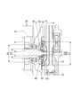
- FIG. 4 is a cross-sectional view of the periphery of the resolver.
- FIG. 5 is a cross-sectional perspective view of the periphery of the resolver.
- FIG. 1 is a schematic diagram of a unit 100 according to this embodiment.
- FIG. 2 is a cross-sectional view of the unit 100 taken along line II-II in FIG. 1.
- FIG. 3 is a cross-sectional view of the unit 100 taken along line III-III in FIG. 1.
- the unit can also be called, for example, a motor unit (a unit having at least a motor) or a power transmission device (a device having at least a power transmission mechanism).
- a motor is a rotating electric machine having an electric motor function and/or a generator function (at least one of an electric motor function and a generator function).
- a power transmission mechanism is, for example, a gear mechanism and/or a differential gear mechanism.
- a device (unit) having a motor and a power transmission mechanism is included in the concepts of both a motor unit and a power transmission device.
- the unit 100 is mounted on a vehicle.
- the vehicle is a converted EV, which is an electric vehicle in which the engine, muffler, fuel tank, etc. have been removed from a gasoline or diesel engine vehicle and a rotating electric machine (such as an electric motor) and batteries have been installed.
- the unit 100 replaces the engine in the base vehicle of the converted EV.
- the application of the unit 100 is not limited to converted EVs, and the unit 100 may be used in other vehicles besides converted EVs.
- the unit 100 is connected to the transmission 2 so that power can be transmitted, and is also connected to the accessory 4 via the accessory pulley 3 so that power can be transmitted.
- the transmission 2, accessory pulley 3, and accessory 4 are from the base vehicle of the converted EV, and are used as is in the converted EV.
- the transmission 2 is, for example, a stepped automatic transmission.
- the accessory 4 is an accessory of the engine of the base vehicle, for example, an alternator. By using an alternator as the accessory 4, it becomes unnecessary to supply power from the EV driving battery to the 12V power supply.
- the accessory 4 may be, for example, an air conditioner compressor or a power steering pump.
- the unit 100 comprises a housing 10, a rotating electric machine 20, a gear mechanism 30, and a resolver 40.
- the housing 10 houses the rotating electric machine 20 and the gear mechanism 30.
- the housing 10 can be composed of multiple case members including a cover, etc.
- the housing 10 can also have support wall portions near the II-II cross section position and near the III-III cross section position that support the bearings of the shaft of the gear mechanism 30.
- the rotating electric machine 20 constitutes the driving source of the vehicle, and includes a rotor 21, a stator 22, and a rotating shaft 23.
- the rotor 21 is provided on the outer periphery of the rotating shaft 23, and the stator 22 houses the rotor 21.
- the rotating shaft 23 protrudes from the rotor 21 to one axial side (the transmission 2 side) corresponding to the left side of FIG. 1.
- the gear mechanism 30 includes a first gear 31, a second gear 32, a third gear 33, a fourth gear 34, a fifth gear 35, a sixth gear 36, a long shaft 37, a first output shaft 38, and a second output shaft 39.
- the first gear 31 is arranged on the first axis AX1 together with the rotating electric machine 20.
- the rotating electric machine 20 and the first gear 31 are arranged coaxially with respect to the first axis AX1.
- arranging a plurality of elements (parts, portions, etc.) on the Nth axis (N is a natural number) is synonymous with arranging a plurality of elements coaxially with respect to the Nth axis.
- the third gear 33, the fourth gear 34, and the fifth gear 35 are arranged on the second axis AX2, and the second gear 32 and the sixth gear 36 are arranged on the third axis AX3.
- the first axis AX1, the second axis AX2, and the third axis AX3 all constitute the axes of the unit 100 and extend along the same direction. Therefore, the extension directions of the first axis AX1, the second axis AX2, and the third axis AX3 all correspond to the axial direction of the unit 100.
- the axial direction refers to the axial direction of the rotating shafts of the components that constitute the unit (e.g., a motor, a gear mechanism, or a differential gear mechanism).
- the radial direction of the unit 100 is a direction perpendicular to either the first axis AX1, the second axis AX2, or the third axis AX3.
- the first gear 31 is connected downstream of the rotating electric machine 20.
- the downstream is the power output side, and with respect to the rotating electric machine 20, the rotor 21 and stator 22 that generate power are used as the reference. Therefore, the downstream of the rotating electric machine 20 can be said to be the downstream of the stator 22. While the downstream is the power output side, the upstream is the power input side.
- the first gear 31 is connected downstream of the rotating electric machine 20 so that power can be transmitted.
- the connection may be via other configurations (for example, a clutch or other gear mechanism).
- the first gear 31 is provided on one axial side of the rotor 21 and is integrated with the rotating shaft 23. Therefore, the first gear 31 rotates integrally with the rotating shaft 23.
- the rotating electric machine 20 and the first gear 31 share the same axis, the first axis AX1.
- the outer diameter of the first gear 31 is set to be smaller than the outer diameter of the rotating electric machine 20.
- the third gear 33 meshes with the first gear 31.
- the third gear 33 has a greater number of teeth than the first gear 31, and together with the first gear 31 constitutes the first reduction mechanism R1.
- the third gear 33 is provided on a long shaft 37.
- the third gear 33 is integrated with the long shaft 37.
- the long shaft 37 extends along the rotating shaft 23 and passes through the outer periphery (the space around the outside) of the stator 22.
- the long shaft 37 extends further axially toward the other end (toward the auxiliary equipment 4) that corresponds to the right side of the stator 22 in FIG. 1.
- the fourth gear 34 is provided on the long shaft 37.
- the fourth gear 34 is connected downstream of the third gear 33 via the long shaft 37.
- the fourth gear 34 is provided on the long shaft 37 at a portion extending axially further than the third gear 33 and the stator 22.
- the fourth gear 34 is integral with the long shaft 37.
- the fifth gear 35 is provided on the long shaft 37.
- the long shaft 37 is located downstream of the third gear 33, and the fifth gear 35 is connected downstream of the third gear 33 via the long shaft 37.
- the fifth gear 35 is provided on a portion of the long shaft 37 that extends axially to one side of the third gear 33.
- the fifth gear 35 is integrated with the long shaft 37.
- the third gear 33, fourth gear 34, and fifth gear 35 share the same axis, with the second axis AX2 as their common axis.
- the power of the rotating electric machine 20 is distributed from the third gear 33 to the fourth gear 34 and fifth gear 35.
- the fourth gear 34 meshes with the second gear 32.
- the second gear 32 is set to have a larger number of teeth than the fourth gear 34, and together with the fourth gear 34 constitutes a second reduction mechanism R2.
- the outer diameter of the second gear 32 is set to be larger than the outer diameter of the rotating electric machine 20.
- the second gear 32 is provided on the second output shaft 39 of the unit 100 and is integrated with the second output shaft 39.
- the second output shaft 39 is connected to the accessory pulley 3.
- the fifth gear 35 meshes with the sixth gear 36.
- the sixth gear 36 is set to have a larger number of teeth than the fifth gear 35, and together with the fifth gear 35 constitutes the third reduction mechanism R3.
- the outer diameter of the sixth gear 36 is set to be larger than the outer diameter of the rotating electric machine 20.
- the sixth gear 36 is provided on the first output shaft 38 of the unit 100 and is integrated with the first output shaft 38.
- the first output shaft 38 is connected to the input shaft of the transmission 2.
- the second gear 32 and the sixth gear 36 have the same axis center with the third shaft AX3 as a common axis.
- the first reduction mechanism R1 and the second reduction mechanism R2 form a two-stage reduction mechanism
- the first reduction mechanism R1 and the third reduction mechanism R3 form a two-stage reduction mechanism.
- the output of the rotating electric machine 20 is transmitted to the second gear 32 via the first gear 31.
- the first gear 31 is connected downstream of the rotating electric machine 20
- the second gear 32 is connected downstream of the first gear 31.
- the second gear 32 is connected downstream of the rotating electric machine 20 via the first gear 31.
- the second gear 32 does not necessarily have to be connected to the first gear 31 and the rotating electric machine 20.
- the second gear 32 may rotate integrally with the rotating shaft 23 of the rotating electric machine 20.
- the unit 100 Compared to when the second gear 32 rotates integrally with the rotating shaft 23 of the rotating electric machine 20, the unit 100 differs in that the output of the rotating electric machine 20 is reduced in two stages before being transmitted to the second gear 32. In other words, the unit 100 can be set to a large reduction ratio, making it possible to design the rotating electric machine 20 to have a smaller maximum torque, and thus making it possible to reduce the size of the rotating electric machine 20.
- the sixth gear 36 has a portion S1 that overlaps with the rotating electric machine 20 when viewed in the axial direction
- the second gear 32 has a portion S2 that overlaps with the rotating electric machine 20 when viewed in the axial direction.
- "Overlapping" when viewed in a specified direction means overlapping in a specified direction, meaning that multiple elements are lined up in the specified direction. For this reason, when a drawing shows multiple elements lined up in a specified direction, it may be assumed that the specification contains a sentence explaining that multiple elements overlap when viewed in a specified direction.
- the protrusion of the gears is suppressed and the radial dimension of the unit 100 can be reduced compared to when the gears do not overlap with the rotating electric machine 20 in the axial view.
- this contributes to the radial miniaturization of the unit 100.
- the width of the installation space in the left-right direction of the vehicle becomes a constraint. With the unit 100, such a constraint can be overcome by miniaturizing the radial direction corresponding to the left-right direction of the vehicle.
- the rotating electric machine 20 and the first gear 31 have a portion sandwiched between the second gear 32 and the sixth gear 36 in the axial direction (a portion sandwiched between portion S1 and portion S2).
- the first gear 31, the second gear 32, and the sixth gear 36 are arranged in a dispersed manner on both axial sides of the rotating electric machine 20. This makes it easier to design the support walls and bearings provided in the housing 10 in a reasonable arrangement compared to a case in which they are densely arranged on one axial side of the rotating electric machine 20, and increases the design freedom of the layout of the unit 100 itself.
- the axis of the first axis AX1 is offset from the axis of the third axis AX3.
- the axis of the first axis AX1 and the axis of the third axis AX3 do not overlap (are offset) when viewed in the axial direction.
- the rotating electric machine 20 is arranged on the first axis AX1. Therefore, the axis of the rotating electric machine 20 is offset from the axis of the second gear 32 and the sixth gear 36 arranged on the third axis AX3.
- the axes of the first axis AX1, the second axis AX2, and the third axis AX3 are arranged in a V-shape when viewed in the axial direction.
- the axis of the first axis AX1 is located at a position that is off the imaginary line that connects the axis of the second axis AX2 and the axis of the third axis AX3.
- an imaginary triangle is formed with the axis of the first axis AX1, the axis of the second axis AX2, and the third axis AX3 as vertices. It can also be said that the axis of the first axis AX1, the axis of the second axis AX2, and the third axis AX3 are not aligned on a straight line.
- the axis of the rotating electric machine 20 by aligning the axis of the rotating electric machine 20 with that of the second gear 32 and the sixth gear 36, the axis of each can be arranged in a straight line when viewed in the axial direction, so it is possible to minimize the protrusion of the gears.
- the rotary electric machine 20 and the second gear 32 and sixth gear 36 are offset in axis, which removes such restrictions and improves design freedom. Even with such offset axis, it is still possible to miniaturize unit 100 to a certain extent, such as to the extent necessary for installation in a converted EV.
- the resolver 40 is provided on the rotating shaft 23 and detects the rotation angle of the rotating electric machine 20.
- the rotating shaft 23 extends in the axial direction on the other side of the rotor 21, i.e., on the opposite side to the first gear 31 side, and the resolver 40 is provided on the rotating shaft 23 at this extended portion.
- the resolver 40 has a portion that is sandwiched between the rotating electric machine 20 and the second gear 32 in the axial direction. This portion is formed in a ring shape around the stepped portion of the rotating shaft 23, and the resolver 40 axially overlaps with the rotor 21 and part of the rotating shaft 23 of the rotating electric machine 20 at this portion, and also overlaps with the second gear 32 in the axial direction.
- the resolver 40 is also arranged together with the second gear 32 on the opposite side of the rotor 21 of the rotating electric machine 20 from the first gear 31 side in the axial direction.
- the resolver 40 is placed on the opposite side of the first gear 31 in the axial direction, where the first gear 31 that connects to the rotating electric machine 20 is located, reducing the available space in the unit 100, and the resolver 40 is placed on the opposite side, together with the second gear 32, so that the space on the opposite side is effectively utilized.
- the second gear 32 is arranged close to the resolver 40.
- the resolver 40 detects the rotation angle of the rotating electric machine 20 using magnetism, as described below. For this reason, if the second gear 32 is arranged close to the resolver 40, there is a concern that the magnetic field of the resolver 40 will change due to the influence of the rotation of the second gear 32, such as the magnetic field lines of the resolver 40 being disturbed by the rotation of the second gear 32, which may affect the detection of the rotation angle of the resolver 40.
- the unit 100 is further configured as follows.
- FIG. 4 is a cross-sectional view of the resolver 40 and its surroundings.
- FIG. 5 is a cross-sectional perspective view of the resolver 40 and its surroundings.
- the resolver 40 has a resolver rotor 41 and a resolver stator 42.
- the resolver rotor 41 is provided on the rotating shaft 23.
- the resolver rotor 41 is housed in the resolver stator 42 and rotates integrally with the rotating shaft 23.
- the resolver stator 42 is formed by winding a resolver coil around a resolver stator core formed by laminating multiple electromagnetic steel plates.
- a gap G is formed between the resolver rotor 41 and the resolver stator 42, and multiple recesses and protrusions are evenly spaced around the circumference of the resolver rotor 41. Therefore, the spacing of the gap G changes periodically with the rotation angle of the resolver rotor 41.
- the outer diameter of the resolver rotor 41 can be set to change gradually around the circumference, that is, the outer circumference changes smoothly around the circumference.
- the resolver coil has an excitation coil and an output coil, and when the gap G changes in response to the rotation of the resolver rotor 41 while excited by the excitation coil, the magnetic permeability also changes. As a result, the output voltage of the output coil changes. Therefore, the rotation angle of the resolver rotor 41 is detected based on the output voltage of the resolver 40, and the rotation angle of the rotating electric machine 20 is detected using magnetism.
- the unit 100 further has a shield member 50.
- the shield member 50 is a magnetic shield member that provides magnetic shielding, and is preferably made of, for example, a ferromagnetic material. Examples of materials that make up a ferromagnetic material include materials whose main components are iron, cobalt, and nickel.
- the shield member 50 has a circular bowl shape, and is attached to the wall portion 10a of the housing 10 from the other axial side, thereby covering the resolver 40 from the other axial side.
- a through hole is provided in the center of the shield member 50, and the end face of the rotating shaft 23 is exposed from the through hole.
- the shield member 50 has a portion sandwiched between the resolver 40 and the second gear 32 in the axial direction (a portion whose radial size is equal to or smaller than the dimension D1, which is the outer diameter of the resolver 40 shown in FIG. 4, and equal to or larger than the dimension D2, which is the inner diameter of the resolver 40).
- the shield member 50 axially overlaps the resolver 40 and the second gear 32 in this portion, and is disposed between the resolver 40 and the second gear 32 in the axial direction. Therefore, even if the second gear 32 disposed near the resolver 40 rotates, the shield member 50 provides a magnetic shield between the second gear 32 and the resolver 40, so that the magnetic field of the resolver 40 is prevented from changing due to the influence of the rotation of the second gear 32.
- the influence of the rotation of the second gear 32 on the magnetic field of the resolver 40 is large when the second gear 32 is made of, for example, a ferromagnetic material.
- the second gear 32 has an annular protrusion 32a that protrudes toward the rotating electric machine 20, i.e., on one axial side.
- the annular protrusion 32a is formed on the outer periphery of the second gear 32 and protrudes on one axial side compared to the surface that is radially inward from the outer periphery.
- the shield member 50 has a portion located radially inside the annular protrusion 32a (the portion on the other axial side from axial position X1, which is the end face position on one axial side of the second gear 32 shown in FIG. 4).
- the shield member 50 in the unit 100, it is possible to position the second gear 32 and the resolver 40 closer together than in the case where the shield member 50 is not provided. This also shortens the axial length of the unit 100.
- the unit 100 further includes a bearing 60.
- the bearing 60 supports the rotating shaft 23 of the rotating electric machine 20.
- the bearing 60 is provided on the wall portion 10a and is supported by the wall portion 10a.
- the bearing 60 and the wall portion 10a have a portion sandwiched between the rotating electric machine 20 and the resolver 40 in the axial direction (a portion whose radial size is equal to or smaller than the dimension D1 and equal to or larger than the dimension D2 shown in FIG. 4).
- the bearing 60 and the wall portion 10a axially overlap the rotor 21 and the resolver 40 of the rotating electric machine 20 in this portion, and are disposed between the rotor 21 and the resolver 40 in the axial direction.
- the reason for providing the bearing 60 and the wall portion 10a in this manner is as follows.
- the rotating electric machine 20 is also one of the elements that affect the magnetic field of the resolver 40, and the influence of the rotating electric machine 20 tends to be greater than that of the second gear 32. Therefore, the influence of the rotating electric machine 20 is reduced by providing a distance between the resolver 40 and the bearing 60, and is further reduced by shielding it with the wall 10a. It is preferable that the wall 10a is made of a ferromagnetic material, for example.
- the resolver 40 has a portion sandwiched between the bearing 60 and the second gear 32 in the axial direction (a portion whose radial size is equal to or smaller than the dimension D3, which is the outer diameter of the bearing 60 shown in FIG. 4, and equal to or larger than the dimension D4, which is the inner diameter of the bearing 60).
- the resolver 40 axially overlaps with the bearing 60 and the second gear 32 in this portion, and is disposed between the bearing 60 and the second gear 32 in the axial direction.
- the unit 100 is configured to reduce the influence of the shield member 50 on the second gear 32. As a result, it is possible to design the second gear 32 so that the distance between the second gear 32 and the shield member 50 is small.
- the unit 100 has a first gear 31, a second gear 32, a rotating electric machine 20, a resolver 40, and a shield member 50.
- the rotating electric machine 20 has a rotating shaft 23 that rotates integrally with the first gear 31.
- the rotating electric machine 20 has a portion sandwiched between the first gear 31 and the second gear 32 in the axial direction.
- the resolver 40 has a portion sandwiched between the rotating electric machine 20 and the second gear 32 in the axial direction as shown in FIG. 3.
- the shield member 50 has a portion sandwiched between the resolver 40 and the second gear 32 in the axial direction as shown in FIG. 4.
- the resolver 40 and the second gear 32 are arranged on the opposite side of the axial first gear 31, where the first gear 31 connected to the rotating electric machine 20 reduces the surplus space in the unit 100, and the space on the opposite side is effectively utilized.
- a shield member 50 is interposed between the resolver 40 and the second gear 32, so that the magnetic field of the resolver 40 can be prevented from changing due to the influence of the rotation of the second gear 32. Therefore, the influence of the rotation of the second gear 32 on the resolver 40 is reduced. From another perspective, it can also be said that since the influence of the rotation of the second gear 32 on the resolver 40 can be reduced, it is possible to bring the second gear 32 and the resolver 40 as close as possible.
- the unit 100 has a bearing 60 that supports the rotating shaft 23 of the rotating electric machine 20, and a wall portion 10a that supports the bearing 60.
- the bearing 60 and the wall portion 10a have a portion that is sandwiched between the rotating electric machine 20 and the resolver 40 in the axial direction as shown in FIG. 4.
- the resolver 40 has a portion that is sandwiched between the bearing 60 and the second gear 32 in the axial direction as shown in FIG. 4.
- the bearings 60 provide a distance between the rotary electric machine 20 and the resolver 40, reducing the degree of influence, and the wall 10a provides shielding to further reduce the degree of influence.
- the shield member 50 reduces the degree of influence on the second gear 32, making it possible to design the second gear 32 with a smaller distance between the shield member 50.
- the second gear 32 has an annular protrusion 32a that protrudes toward the rotating electric machine 20.
- the shield member 50 has a portion that is located radially inward of the annular protrusion 32a, as shown in FIG. 4.
- the gear mechanism 30 is not necessarily limited to a speed reduction mechanism, but may also be a speed increase mechanism.
Landscapes
- Engineering & Computer Science (AREA)
- Power Engineering (AREA)
- Motor Or Generator Frames (AREA)
- Transmission And Conversion Of Sensor Element Output (AREA)
Priority Applications (1)
| Application Number | Priority Date | Filing Date | Title |
|---|---|---|---|
| JP2024570072A JPWO2024150550A1 (https=) | 2023-01-10 | 2023-11-27 |
Applications Claiming Priority (2)
| Application Number | Priority Date | Filing Date | Title |
|---|---|---|---|
| JP2023-001861 | 2023-01-10 | ||
| JP2023001861 | 2023-01-10 |
Publications (1)
| Publication Number | Publication Date |
|---|---|
| WO2024150550A1 true WO2024150550A1 (ja) | 2024-07-18 |
Family
ID=91896817
Family Applications (1)
| Application Number | Title | Priority Date | Filing Date |
|---|---|---|---|
| PCT/JP2023/042323 Ceased WO2024150550A1 (ja) | 2023-01-10 | 2023-11-27 | ユニット |
Country Status (2)
| Country | Link |
|---|---|
| JP (1) | JPWO2024150550A1 (https=) |
| WO (1) | WO2024150550A1 (https=) |
Citations (4)
| Publication number | Priority date | Publication date | Assignee | Title |
|---|---|---|---|---|
| JP2011217519A (ja) * | 2010-03-31 | 2011-10-27 | Aisin Aw Co Ltd | レゾルバの電磁遮蔽構造 |
| JP2012228024A (ja) * | 2011-04-18 | 2012-11-15 | Toyota Motor Corp | レゾルバ |
| JP2019074409A (ja) * | 2017-10-16 | 2019-05-16 | トヨタ自動車株式会社 | 回転電機 |
| JP2022168661A (ja) * | 2021-04-26 | 2022-11-08 | ジヤトコ株式会社 | 配置構造 |
-
2023
- 2023-11-27 JP JP2024570072A patent/JPWO2024150550A1/ja active Pending
- 2023-11-27 WO PCT/JP2023/042323 patent/WO2024150550A1/ja not_active Ceased
Patent Citations (4)
| Publication number | Priority date | Publication date | Assignee | Title |
|---|---|---|---|---|
| JP2011217519A (ja) * | 2010-03-31 | 2011-10-27 | Aisin Aw Co Ltd | レゾルバの電磁遮蔽構造 |
| JP2012228024A (ja) * | 2011-04-18 | 2012-11-15 | Toyota Motor Corp | レゾルバ |
| JP2019074409A (ja) * | 2017-10-16 | 2019-05-16 | トヨタ自動車株式会社 | 回転電機 |
| JP2022168661A (ja) * | 2021-04-26 | 2022-11-08 | ジヤトコ株式会社 | 配置構造 |
Also Published As
| Publication number | Publication date |
|---|---|
| JPWO2024150550A1 (https=) | 2024-07-18 |
Similar Documents
| Publication | Publication Date | Title |
|---|---|---|
| US11014455B2 (en) | Vehicle drive device | |
| CN106059171B (zh) | 电机装置、机动车辆变速箱及用于生产电机装置的方法 | |
| CN101678753B (zh) | 混合动力驱动装置 | |
| CN111279101B (zh) | 车辆用驱动装置 | |
| CN111886783B (zh) | 车辆用驱动装置 | |
| JP3627337B2 (ja) | 電気自動車用駆動装置 | |
| CN103764422A (zh) | 车辆用驱动装置 | |
| EP3783778A1 (en) | Dynamo-electric machine, and drive device for vehicle comprising dynamo-electric machine | |
| US8142317B2 (en) | Power transmission apparatus of hybrid vehicle | |
| US20220154810A1 (en) | Power transmission device | |
| CN100521419C (zh) | 混合动力车辆用驱动装置及其制造方法 | |
| CN104852501B (zh) | 驱动装置的壳体结构 | |
| JP6160633B2 (ja) | 駆動装置 | |
| JP7451838B2 (ja) | 動力伝達装置 | |
| WO2024150550A1 (ja) | ユニット | |
| US7001297B2 (en) | Hybrid transmission | |
| WO2015193715A1 (en) | Switched reluctance motor | |
| KR102159796B1 (ko) | 전기자동차 구동장치 | |
| JP7676667B2 (ja) | ユニット | |
| JP2010221775A (ja) | ハイブリッド車用動力伝達装置 | |
| WO2024135164A1 (ja) | ユニット | |
| JP2007159287A (ja) | 車両用駆動装置の電動機支持機構 | |
| CN118891459A (zh) | 车用驱动装置 | |
| JP7811267B2 (ja) | ユニット | |
| WO2024135165A1 (ja) | ユニット |
Legal Events
| Date | Code | Title | Description |
|---|---|---|---|
| 121 | Ep: the epo has been informed by wipo that ep was designated in this application |
Ref document number: 23915191 Country of ref document: EP Kind code of ref document: A1 |
|
| WWE | Wipo information: entry into national phase |
Ref document number: 2024570072 Country of ref document: JP |
|
| NENP | Non-entry into the national phase |
Ref country code: DE |
|
| 122 | Ep: pct application non-entry in european phase |
Ref document number: 23915191 Country of ref document: EP Kind code of ref document: A1 |