WO2024150327A1 - 予測装置、学習装置、予測システム、予測方法、及びプログラム - Google Patents
予測装置、学習装置、予測システム、予測方法、及びプログラム Download PDFInfo
- Publication number
- WO2024150327A1 WO2024150327A1 PCT/JP2023/000453 JP2023000453W WO2024150327A1 WO 2024150327 A1 WO2024150327 A1 WO 2024150327A1 JP 2023000453 W JP2023000453 W JP 2023000453W WO 2024150327 A1 WO2024150327 A1 WO 2024150327A1
- Authority
- WO
- WIPO (PCT)
- Prior art keywords
- terminal
- wireless communication
- prediction
- communication quality
- information
- Prior art date
- Legal status (The legal status is an assumption and is not a legal conclusion. Google has not performed a legal analysis and makes no representation as to the accuracy of the status listed.)
- Ceased
Links
Images







Classifications
-
- H—ELECTRICITY
- H04—ELECTRIC COMMUNICATION TECHNIQUE
- H04W—WIRELESS COMMUNICATION NETWORKS
- H04W24/00—Supervisory, monitoring or testing arrangements
- H04W24/08—Testing, supervising or monitoring using real traffic
Definitions
- the present invention relates to a technology for predicting wireless communication quality in a wireless communication system.
- quality prediction technology that predicts wireless communication quality to ensure stable use of wireless communication.
- Conventional quality prediction technology predicts wireless communication quality from the current terminal position and movement information, for example, based on the actual communication quality value for the terminal position acquired in advance.
- Non-Patent Document 1 also discloses a technology that uses the most recent time series data of received power to predict future received power (an example of wireless communication quality) through a time series prediction method such as an RNN (Recurrent Neural Network). By using the most recent time series data, it is possible to predict fluctuations that change moment by moment due to the surrounding dynamic environment.
- a time series prediction method such as an RNN (Recurrent Neural Network).
- Motoharu Sasaki et al. "Prediction of Radio Wave Propagation Loss Variation in the 2-26 GHz Band Using LSTM," IEICE Technical Report, vol. 120, no. 325, AP2020-112, pp. 50-55, January 2021
- the present invention has been made in consideration of the above points, and aims to provide technology that makes it possible to improve the accuracy of predicting wireless communication quality.
- a prediction device for predicting wireless communication quality in a terminal performing wireless communication, the prediction device comprising: a quality prediction processing unit that predicts wireless communication quality of the terminal at a future time based on first environmental information, which is peripheral environment information of the terminal at a certain time, second environmental information, which is peripheral environment information of the terminal at the future time relative to the certain time, and data on wireless communication quality of the terminal; and an output unit that outputs the wireless communication quality predicted by the quality prediction processing unit.
- the disclosed technology makes it possible to improve the accuracy of predicting wireless communication quality.
- FIG. 13 is a diagram showing a processing image of the conventional technique 2.
- FIG. 1 is a diagram for explaining a problem in the conventional technique 1.
- FIG. 13 is a diagram for explaining a problem of the conventional technique 2.
- 1 is a diagram illustrating an example of a configuration of a wireless communication system according to an embodiment of the present invention.
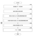
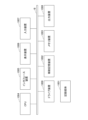
- FIG. 1 illustrates an example of the configuration of a prediction device 100. 1 is a flowchart illustrating an operation of the prediction device 100.
- FIG. 13 is a diagram illustrating an example of a prediction model.
- FIG. 13 is a diagram illustrating an example of a prediction model.
- FIG. 13 is a diagram showing an example of a prediction result obtained by a prediction model after 5 seconds.
- FIG. 11 is a diagram for explaining environmental information.
- FIG. 11 is a diagram for explaining environmental information.
- FIG. 2 illustrates an example of the configuration of a learning device 200. 10 is a flowchart for explaining the operation of the learning device 200.
- the received power at the receiving point (terminal) and the radio wave propagation loss are used as examples of the wireless communication quality to be predicted, but the wireless communication quality to be predicted is not limited to these.
- the wireless communication quality to be predicted may be, for example, the transmission rate, throughput, RSRQ, SINR, etc.
- a conventional quality prediction technology is one that predicts wireless communication quality from the current terminal location and movement information based on the actual communication quality value for the terminal location acquired in advance (referred to as conventional technology 1).
- Another conventional technology is to predict future received power (an example of wireless communication quality) using time series data of the most recent received power through a time series prediction method such as an RNN (Recurrent Neural Network) (referred to as conventional technology 2).
- RNN Recurrent Neural Network
- Fig. 1 is a diagram showing a processing image of conventional technology 2.
- a device for predicting wireless communication quality acquires time series data of received power at a terminal, and predicts future received power using the most recent past time series data at the time (present) when the received power is predicted. By using the most recent time series data, it is possible to predict quality fluctuations that change from moment to moment due to the surrounding dynamic environment.
- the prediction device 100 predicts the wireless communication quality (specifically, the received power) of a terminal 2 that wirelessly communicates with a base station 1 .
- the prediction device 100 uses a time series prediction approach such as an RNN to predict the received power at the predicted target position of the terminal 2 by using time series data of the most recent received power at the terminal 2, as well as environmental information of the current position of the terminal 2 and environmental information of the predicted target position of the terminal 2.
- a time series prediction approach such as an RNN to predict the received power at the predicted target position of the terminal 2 by using time series data of the most recent received power at the terminal 2, as well as environmental information of the current position of the terminal 2 and environmental information of the predicted target position of the terminal 2.
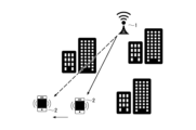
- Fig. 4 shows an example of the configuration of a wireless communication system according to this embodiment.
- This wireless communication system includes a base station 1, a terminal 2, and a prediction device 100.
- Fig. 4 shows one base station 1 and one terminal 2, a plurality of base stations and a plurality of terminals are generally provided.
- the terminal 2 is a device (e.g., a smartphone) that performs wireless communication with the base station 1.
- the base station 1 may be a wireless LAN base station (access point), a base station (e.g., gNB) in a cellular communication system such as 5G, or a base station of a wireless system other than these.
- the prediction device 100 is a device that predicts the received power at the terminal 2 based on the technology according to the present invention.
- the prediction device 100 is capable of acquiring information necessary for prediction via a network.
- the function of the prediction device 100 may be held by the terminal 2 or the base station 1. In other words, the terminal 2 or the base station 1 may function as the prediction device 100.
- Fig. 5 shows an example of the configuration of the prediction device 100.
- the prediction device 100 has a received power acquisition unit 110, a terminal position acquisition unit 120, an environment information holding unit 130, a terminal position information holding unit 140, a received power information holding unit 150, a terminal position prediction processing unit 160, a surrounding environment information extraction unit 170, a received power prediction processing unit 180, a prediction model holding unit 190, and an output unit 195.
- the received power prediction processing unit 180 may be called a quality prediction processing unit.
- wireless communication quality such as received power is predicted using a neural network prediction model.
- a trained model (trained parameters, etc.) is stored in the prediction model holding unit 190, and the received power prediction processing unit 180 predicts received power using the prediction model read from the prediction model holding unit 190.
- a neural network as a prediction model is one example.
- a machine learning model other than a neural network e.g., a regression model may also be used as the prediction model.
- the "prediction device 100 including the received power acquisition unit 110, terminal position acquisition unit 120, environmental information holding unit 130, terminal position information holding unit 140, received power information holding unit 150, terminal position prediction processing unit 160, surrounding environment information extraction unit 170, received power prediction processing unit 180, prediction model holding unit 190, and output unit 195" may be realized in one device (computer) or multiple computers.
- the prediction device 100 may be equipped with the "received power prediction processing unit 180, prediction model holding unit 190, and output unit 195," and other functional units may be provided in one or multiple separate devices provided outside the prediction device 100.
- the prediction device 100 when the prediction device 100 is configured by multiple computers, the prediction device 100 may be called a prediction system.
- the "received power prediction processing unit 180 and the output unit 195" may be configured by one computer
- the terminal position prediction processing unit 160 may be configured by another computer
- a system including these may be the prediction system.
- the storage units (130, 140, 150, 190) may each be a storage device (memory, etc.) in a computer (prediction device 100) or a database device in a prediction system.
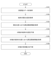
- the reception power acquisition unit 110 acquires data on the reception power of the terminal 2 and stores the received data together with time information in the reception power information storage unit 150.
- the process of S101 is performed, for example, at regular time intervals.
- the time-series data on the reception power of the terminal 2 is stored in the reception power information storage unit 150.
- the received power acquisition unit 110 may acquire data on the received power from the terminal 2 by communicating with the terminal 2, or another device (e.g., base station 1) may acquire data on the received power of the terminal 2, and the received power acquisition unit 110 may acquire the data on the received power of the terminal 2 from the other device.
- another device e.g., base station 1
- the received power acquisition unit 110 may acquire the data on the received power of the terminal 2 from the other device.
- the terminal location acquisition unit 120 acquires information on the current location of the terminal 2, and stores the acquired location information together with time information in the terminal location information storage unit 140.
- the process of S102 is performed, for example, at regular time intervals.
- the terminal position acquisition unit 120 may acquire position information from the terminal 2 by communicating with the terminal 2, or another device (e.g., base station 1) may acquire the position information of the terminal 2, and the terminal position acquisition unit 120 may acquire the position information of the terminal 2 from the other device.
- another device e.g., base station 1
- the terminal position acquisition unit 120 may acquire the position information of the terminal 2 from the other device.
- the environmental information holding unit 130 holds environmental information for a target area for which prediction is performed by the prediction device 100.
- the environmental information stored in the environmental information holding unit 130 is information that serves as a source for generating input data for the environmental information to be input to the prediction model.
- the environmental information stored in the environmental information holding unit 130 may be, for example, 3D map data.
- the surrounding environment information extraction unit 190 acquires surrounding environment information for the current position of the terminal 2 by referring to the environment information storage unit 130.
- the surrounding environment information is, for example, the average building height between the terminal 2 and the base station 1, the building density around the terminal 2, etc.
- the terminal position prediction processing unit 160 predicts the position of the terminal 2 t seconds after the current time. Any method may be used to predict the future position. For example, the terminal position prediction processing unit 160 may read time series data of the most recent past position of the terminal 2 from the terminal position information storage unit 140, and predict the future position based on the time series data.
- the surrounding environment information extraction unit 190 acquires surrounding environment information for the position of the terminal 2 t seconds later by referring to the environment information storage unit 130.
- the surrounding environment information is the same as the information in S103, and is, for example, the average building height between the terminal 2 and the base station 1, the building density around the terminal 2, and the like.
- the reception power prediction processing unit 180 predicts the reception power of terminal 2 t seconds later using the most recent time series data of the reception power of terminal 2 read from the reception power information storage unit 150, the surrounding environment information at the current location of terminal 2 acquired in S103, and the surrounding environment information at the terminal location t seconds later acquired in S104.
- the received power prediction processing unit 180 inputs the time series data of the received power, the surrounding environment information of the current location, and the surrounding environment information of the future location into the trained prediction model read from the prediction model storage unit 190, and obtains the received power of the terminal 2 after t seconds as the output from the prediction model.
- the information on the received power of terminal 2 after t seconds obtained by the received power prediction processing unit 180 is output from the output unit 195.
- the most recent time series data of the received power of terminal 2 is time series data of a certain length of time immediately before the current time.
- the time series data of the received power is not limited to the most recent data, and may be time series data from a certain time in the past.
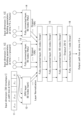
- FIG. 7 shows an example of the configuration of a prediction model used in the received power prediction processing unit 180.
- the prediction model includes an input layer 11, an RNN layer 12, a fully connected layer 13, a fully connected layer 14, a fully connected layer 15, and an output layer 16.
- Time series data of the most recent received power at terminal 2 is input to input layer 11.
- Environmental information data around the current position of terminal 2 is input as scalar data to fully connected layer 13.
- Environmental information data around the prediction target position of terminal 2 is input as scalar data to fully connected layer 14.
- the output from each node in the fully connected layer 15 is input to the output layer 16, which outputs a predicted value of the received power at the destination position of terminal 2 (position t seconds later).
- Figure 8 shows an example of predicting radio wave propagation loss (path loss), which is an example of wireless communication quality.
- Radio wave propagation loss is a value calculated from received power, transmitted power, antenna gain, etc.
- time-series data of radio wave propagation loss (p t ) for 50 time steps is input from the input layer 11.
- the RNN layer 12 is a GRU with 50 nodes, and radio wave propagation loss is input to each node.
- the fully connected layer 13 receives environmental information data (Building parameters) for the current terminal position (time t in Figure 8).
- the fully connected layer 14 receives environmental information data (Building parameters) for the predicted terminal position 5 seconds later (time t + 5).
- the outputs of the RNN layer 12, the fully connected layer 13, and the fully connected layer 14 are input to the fully connected layer 15, and the predicted value of the radio wave propagation loss at time t+5 is output from the output layer 16.
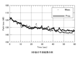
- Figure 9 shows an example of the prediction results (prop.) obtained by the prediction model 5 seconds later.
- Figure 9 also shows the measurement data (Meas.) at the time of the prediction. As shown in Figure 9, it can be seen that radio wave propagation loss is predicted with high accuracy.
- FIG. 10 environment side view
- Figure 11 environment overhead view
- Tx corresponds to base station 1
- Rx corresponds to terminal 2.
- Tx-Rx is, for example, "a straight line connecting Tx and Rx” when viewed from an overhead view (a view from above).
- Wm width between Tx-Rx is a rectangular area with Tx and Rx at both ends and a width of Wm, as shown in Figure 11A.
- closest can be rephrased as "nearest”.
- Tx Distance from Tx to the nearest building between Tx and Rx h bTx : Height of the nearest building from Tx between Tx and Rx h max : Height of the tallest building between Tx and Rx d max : Distance from Rx to the tallest building between Tx and Rx h mean : Average building height between Tx and Rx d
- Rx1 Distance from Rx to the nearest building between Tx and Rx h bRx1 : Height of the nearest building from Rx between Tx and Rx d
- Rx2 Distance from Rx to the nearest building on the line connecting Tx and Rx h bRx2 : Height of the nearest building on the line connecting Tx and Rx N b : Number of buildings between Tx and Rx r Rx : Building area ratio within a circle Dm around Rx (D is, for example, 200)
- r TxRx Building area ratio in Wm width between Tx and Rx (W is, for example, 10)
- the prediction model used in this embodiment is not limited to the prediction models shown in Figures 7 and 8. Prediction models other than the prediction models shown in Figures 7 and 8 may be used. Furthermore, the environmental information data is not limited to the data (parameters) described above.
- a prediction model can be learned using a learning device 200 shown in Fig. 12.
- the learning device 200 shown in Fig. 12 is a device obtained by deleting the received power prediction processing unit 180 from the prediction device 100 (or the prediction system) shown in Fig. 5 and adding a learning unit 210.
- the learning device 200 and the prediction device 100 are separate devices, but by adding a learning unit 210 to the prediction device 100, the prediction device 100 may perform both learning and prediction.
- the configuration of the prediction model during learning and the contents of the environmental information are the same as the configuration of the prediction model during prediction and the contents of the environmental information described above.
- the received power acquisition unit 110 acquires data on the received power of the terminal 2, and stores the received data together with time information in the received power information storage unit 150.
- the terminal location acquisition unit 120 acquires information on the location of the terminal 2, and stores the acquired location information together with time information in the terminal location information storage unit 140.
- the processes of S201 and S202 are performed, for example, at regular time intervals.
- reception power information/terminal location information for a certain period is accumulated in the reception power information storage unit 150/terminal location information storage unit 140, the accumulated information is used to learn a prediction model.
- the surrounding environment information extraction unit 190 acquires surrounding environment information for the position of the terminal 2 at a certain time (time k) by referring to the terminal position information storage unit 140 and the environment information storage unit 130.
- the surrounding environment information extraction unit 190 acquires surrounding environment information for the location of the terminal 2 t seconds later (time k+t) by referring to the terminal position information storage unit 140 and the environment information storage unit 130.
- the learning unit 210 inputs "time series data of the most recent received power of terminal 2 for time k read from the received power information storage unit 150, surrounding environment information of the terminal position at time k, and surrounding environment information of the terminal position at time k+t" into the prediction model (prediction model in the middle of learning) read from the prediction model storage unit 190, and obtains the received power of terminal 2 at time k+t as an output from the prediction model.
- the learning unit 210 adjusts (updates) the parameters of the prediction model based on the error between the received power of terminal 2 at time k+t obtained from the prediction model and the received power of terminal 2 at time k+t read from the received power information storage unit 150 (the correct received power). In other words, the parameters of the prediction model are updated to reduce the error.
- the prediction model with updated parameters is stored in the prediction model storage unit 190.
- the process from S203 to S206 is repeatedly executed while updating the time k, thereby obtaining a trained prediction model.
- the trained prediction model is output from the output unit 195, input to the prediction device 100, and used for prediction in the prediction device 100.
- Any of the devices described in this embodiment can be realized, for example, by causing a computer to execute a program.
- This computer may be a physical computer or a virtual machine on the cloud.
- the device can be realized by using hardware resources such as a CPU and memory built into a computer to execute a program corresponding to the processing performed by the device.
- the program can be recorded on a computer-readable recording medium (such as a portable memory) and then stored or distributed.
- the program can also be provided via a network such as the Internet or email.
- FIG. 14 is a diagram showing an example of the hardware configuration of the computer.
- the computer in FIG. 14 has a drive device 1000, an auxiliary storage device 1002, a memory device 1003, a CPU 1004, an interface device 1005, a display device 1006, an input device 1007, an output device 1008, etc., all of which are interconnected by a bus BS.
- the computer may further include a GPU.
- the program that realizes the processing on the computer is provided by a recording medium 1001, such as a CD-ROM or a memory card.
- a recording medium 1001 storing the program is set in the drive device 1000, the program is installed from the recording medium 1001 via the drive device 1000 into the auxiliary storage device 1002.
- the program does not necessarily have to be installed from the recording medium 1001, but may be downloaded from another computer via a network.
- the auxiliary storage device 1002 stores the installed program as well as necessary files, data, etc.
- the memory device 1003 When an instruction to start a program is received, the memory device 1003 reads out and stores the program from the auxiliary storage device 1002.
- the CPU 1004 realizes the functions related to the device in accordance with the program stored in the memory device 1003.
- the interface device 1005 is used as an interface for connecting to a network, etc.
- the display device 1006 displays a GUI (Graphical User Interface) based on a program, etc.
- the input device 1007 is composed of a keyboard and mouse, buttons, a touch panel, etc., and is used to input various operational instructions.
- the output device 1008 outputs the results of calculations.
- the technique described in the present embodiment makes it possible to improve the prediction accuracy of wireless communication quality.
- the surrounding environment information of the current location of terminal 2 and the surrounding environment information of the target prediction location in addition to the most recent wireless communication quality data, it is possible to incorporate both quality fluctuations in a dynamic environment and quality fluctuations due to a static environment as information, thereby improving the accuracy of wireless communication quality prediction.
- a prediction device for predicting wireless communication quality in a terminal performing wireless communication Memory, at least one processor coupled to the memory; Including, The processor, predicting wireless communication quality of the terminal at a future time from first environmental information which is peripheral environment information of the terminal at a certain time, second environmental information which is peripheral environment information of the terminal at the future time relative to the certain time, and data on wireless communication quality of the terminal; The prediction device outputs a predicted wireless communication quality.
- the prediction device according to claim 1 wherein the data on the wireless communication quality is time-series data on the wireless communication quality in the past immediately before the time.
- the prediction device (Additional Note 3) The prediction device according to claim 1 or 2, wherein the first environmental information and the second environmental information each include information about a building that exists between the terminal and a base station that wirelessly communicates with the terminal.
- a learning device that learns a prediction model used to predict wireless communication quality in a terminal that performs wireless communication, Memory, at least one processor coupled to the memory; Including, The processor, inputting first environmental information, which is information on the surrounding environment of the terminal at a certain time, second environmental information, which is information on the surrounding environment of the terminal at a future time relative to the certain time, and data on wireless communication quality at the terminal, into the prediction model; learning the prediction model using a predicted value of wireless communication quality obtained from the prediction model and correct answer data of wireless communication quality at the future time of the terminal; The memory stores the predictive model.
- a prediction system for predicting wireless communication quality in a terminal that performs wireless communication a terminal position prediction processing unit that predicts a future position of the terminal, which is a position of the terminal at a future time relative to a certain time; a quality prediction processing unit that predicts a wireless communication quality of the terminal at the future time based on first environmental information that is peripheral environment information of the terminal at the time, second environmental information that is peripheral environment information of the terminal at the future time, and data on wireless communication quality of the terminal; and an output unit that outputs the wireless communication quality predicted by the quality prediction processing unit.
- a prediction method executed by a computer to predict wireless communication quality in a terminal that performs wireless communication comprising: a prediction step of predicting wireless communication quality of the terminal at a future time from first environmental information, which is information on the surrounding environment of the terminal at a certain time, second environmental information, which is information on the surrounding environment of the terminal at a future time relative to the certain time, and data on wireless communication quality of the terminal; and outputting the wireless communication quality predicted by the prediction step.
- a non-transitory storage medium storing a program for causing a computer to function as each unit in the prediction device according to any one of claims 1 to 3.
Landscapes
- Engineering & Computer Science (AREA)
- Computer Networks & Wireless Communication (AREA)
- Signal Processing (AREA)
- Mobile Radio Communication Systems (AREA)
Priority Applications (2)
| Application Number | Priority Date | Filing Date | Title |
|---|---|---|---|
| PCT/JP2023/000453 WO2024150327A1 (ja) | 2023-01-11 | 2023-01-11 | 予測装置、学習装置、予測システム、予測方法、及びプログラム |
| JP2024569908A JPWO2024150327A1 (https=) | 2023-01-11 | 2023-01-11 |
Applications Claiming Priority (1)
| Application Number | Priority Date | Filing Date | Title |
|---|---|---|---|
| PCT/JP2023/000453 WO2024150327A1 (ja) | 2023-01-11 | 2023-01-11 | 予測装置、学習装置、予測システム、予測方法、及びプログラム |
Publications (1)
| Publication Number | Publication Date |
|---|---|
| WO2024150327A1 true WO2024150327A1 (ja) | 2024-07-18 |
Family
ID=91896699
Family Applications (1)
| Application Number | Title | Priority Date | Filing Date |
|---|---|---|---|
| PCT/JP2023/000453 Ceased WO2024150327A1 (ja) | 2023-01-11 | 2023-01-11 | 予測装置、学習装置、予測システム、予測方法、及びプログラム |
Country Status (2)
| Country | Link |
|---|---|
| JP (1) | JPWO2024150327A1 (https=) |
| WO (1) | WO2024150327A1 (https=) |
Cited By (1)
| Publication number | Priority date | Publication date | Assignee | Title |
|---|---|---|---|---|
| WO2026069549A1 (ja) * | 2024-09-26 | 2026-04-02 | Ntt株式会社 | 情報処理装置、リアルタイム品質指標算出方法、及びプログラム |
Citations (4)
| Publication number | Priority date | Publication date | Assignee | Title |
|---|---|---|---|---|
| JP2009134394A (ja) * | 2007-11-29 | 2009-06-18 | Sony Corp | 情報処理装置、情報処理方法、及びプログラム |
| JP2009278421A (ja) * | 2008-05-15 | 2009-11-26 | Nec Corp | 無線品質劣化予測システム |
| JP2020088402A (ja) * | 2018-11-14 | 2020-06-04 | 富士通株式会社 | 通信装置、及び通信方法 |
| JP2020191555A (ja) * | 2019-05-22 | 2020-11-26 | Kddi株式会社 | 受信電力推定装置、受信電力推定方法およびプログラム |
Family Cites Families (1)
| Publication number | Priority date | Publication date | Assignee | Title |
|---|---|---|---|---|
| JP7276431B2 (ja) * | 2019-04-26 | 2023-05-18 | 日本電信電話株式会社 | 通信システム及び基地局 |
-
2023
- 2023-01-11 WO PCT/JP2023/000453 patent/WO2024150327A1/ja not_active Ceased
- 2023-01-11 JP JP2024569908A patent/JPWO2024150327A1/ja active Pending
Patent Citations (4)
| Publication number | Priority date | Publication date | Assignee | Title |
|---|---|---|---|---|
| JP2009134394A (ja) * | 2007-11-29 | 2009-06-18 | Sony Corp | 情報処理装置、情報処理方法、及びプログラム |
| JP2009278421A (ja) * | 2008-05-15 | 2009-11-26 | Nec Corp | 無線品質劣化予測システム |
| JP2020088402A (ja) * | 2018-11-14 | 2020-06-04 | 富士通株式会社 | 通信装置、及び通信方法 |
| JP2020191555A (ja) * | 2019-05-22 | 2020-11-26 | Kddi株式会社 | 受信電力推定装置、受信電力推定方法およびプログラム |
Cited By (1)
| Publication number | Priority date | Publication date | Assignee | Title |
|---|---|---|---|---|
| WO2026069549A1 (ja) * | 2024-09-26 | 2026-04-02 | Ntt株式会社 | 情報処理装置、リアルタイム品質指標算出方法、及びプログラム |
Also Published As
| Publication number | Publication date |
|---|---|
| JPWO2024150327A1 (https=) | 2024-07-18 |
Similar Documents
| Publication | Publication Date | Title |
|---|---|---|
| US11410046B2 (en) | Learning-based service migration in mobile edge computing | |
| US12034495B2 (en) | System, device, method and program that predict communication quality | |
| US11170293B2 (en) | Multi-model controller | |
| WO2022097270A1 (ja) | 学習方法、無線品質推定方法、学習装置、無線品質推定装置、及びプログラム | |
| US20240354659A1 (en) | Method for Updating Model and Communication Device | |
| WO2024150327A1 (ja) | 予測装置、学習装置、予測システム、予測方法、及びプログラム | |
| Hao et al. | Topology optimised fixed‐time consensus for multi‐UAV system in a multipath fading channel | |
| JP2025028118A (ja) | 制御システム、制御方法、及びプログラム | |
| JP7841613B2 (ja) | 推定装置、学習装置、推定方法、学習方法、及びプログラム | |
| JP7276481B2 (ja) | 移動端末及び通信品質予測方法 | |
| WO2022219755A1 (ja) | 通信制御システム、通信制御方法、及びプログラム | |
| Jiang et al. | Learning on the fly: An RNN-based online throughput prediction framework for UAV communications | |
| US20250094664A1 (en) | Tilt angle optimization apparatus, tilt angle optimization method, and program | |
| CN116996907A (zh) | 数据处理方法、装置、设备及计算机可读存储介质 | |
| CN117318777A (zh) | 由基站执行的方法、基站及计算机可读存储介质 | |
| JP7568074B2 (ja) | 通信制御システム、通信制御方法、及びプログラム | |
| JP7694650B2 (ja) | 通信制御システム、通信制御方法、及びプログラム | |
| JP7111159B2 (ja) | 情報共有装置、情報共有方法および情報共有プログラム | |
| WO2024089820A1 (ja) | 情報配信装置、予測システム、情報配信方法、及びプログラム | |
| WO2025150115A1 (ja) | 無線通信装置及び無線通信方法 | |
| JP7655380B2 (ja) | システム、方法、及びプログラム | |
| US20250386323A1 (en) | Radio communication system, control apparatus, move destination position determination method, and program | |
| US20250386324A1 (en) | Radio communication system, control apparatus, move destination position determination method, and program | |
| JP2025026599A (ja) | 通信制御システム、通信制御方法、及びプログラム | |
| CN120238833A (zh) | 信息上报方法、装置、第一设备及第二设备 |
Legal Events
| Date | Code | Title | Description |
|---|---|---|---|
| 121 | Ep: the epo has been informed by wipo that ep was designated in this application |
Ref document number: 23915951 Country of ref document: EP Kind code of ref document: A1 |
|
| WWE | Wipo information: entry into national phase |
Ref document number: 2024569908 Country of ref document: JP |
|
| NENP | Non-entry into the national phase |
Ref country code: DE |
|
| 122 | Ep: pct application non-entry in european phase |
Ref document number: 23915951 Country of ref document: EP Kind code of ref document: A1 |