WO2024150300A1 - 通信ネットワークの状況に応じた方法でデータを転送する装置及び方法 - Google Patents
通信ネットワークの状況に応じた方法でデータを転送する装置及び方法 Download PDFInfo
- Publication number
- WO2024150300A1 WO2024150300A1 PCT/JP2023/000395 JP2023000395W WO2024150300A1 WO 2024150300 A1 WO2024150300 A1 WO 2024150300A1 JP 2023000395 W JP2023000395 W JP 2023000395W WO 2024150300 A1 WO2024150300 A1 WO 2024150300A1
- Authority
- WO
- WIPO (PCT)
- Prior art keywords
- communication
- communication path
- data
- path
- established
- Prior art date
- Legal status (The legal status is an assumption and is not a legal conclusion. Google has not performed a legal analysis and makes no representation as to the accuracy of the status listed.)
- Ceased
Links
Images




Classifications
-
- H—ELECTRICITY
- H04—ELECTRIC COMMUNICATION TECHNIQUE
- H04L—TRANSMISSION OF DIGITAL INFORMATION, e.g. TELEGRAPHIC COMMUNICATION
- H04L69/00—Network arrangements, protocols or services independent of the application payload and not provided for in the other groups of this subclass
- H04L69/16—Implementation or adaptation of Internet protocol [IP], of transmission control protocol [TCP] or of user datagram protocol [UDP]
- H04L69/165—Combined use of TCP and UDP protocols; selection criteria therefor
Definitions
- This disclosure relates to communication control for data collection.
- TCP Transmission Control Protocol
- RDMA Remote Direct Memory Access
- a communication system In order to realize data transfer by RDMA in a wide area network, a communication system has been proposed in which a communication path is established between a data source and a server, and the data source and server perform RDMA communication using the established communication path (for example, non-patent document 1).
- the purpose of this disclosure is to adjust server load and network efficiency by selecting a transfer method based on the status of the communication network.
- the present disclosure relates to a communication system for transmitting data from a data source to a server, comprising: A first communication method for establishing a communication path from a data source to a server; A second communication method that does not establish a communication path from the data source to the server; Any of the above is acceptable.
- the first communication method and the second communication method are used selectively based on a situation in the communication network in which the communication path is established.
- the first communication method for example, is a path linkage RDMA method.
- the second communication method is, for example, the TCP method.
- the device of the present disclosure comprises: determining whether to establish the communication path based on a status of the communication network through which the communication path is to be established; When it is determined that the communication path is to be established, the data source is caused to transmit data using a communication method for establishing the communication path; When it is determined that the communication path is not to be established, the data source is caused to transmit data using a communication method that does not establish the communication path.
- the device disclosed herein is any device provided in the communication system, such as the data source, or a path controller that manages the communication path connecting the data source and the server.
- the apparatus of the present disclosure functions as a path controller that establishes a communication path from a data source to a server, determining whether to establish the communication path based on a status of the communication network through which the communication path is to be established; When it is determined that the communication path is to be established, the communication path is established; When it is determined that the communication path is not to be established, the communication method in which the communication path is not to be established is notified to the data source.
- the state of the communication network is, for example, the load on the communication network caused by establishing the communication path.
- the path controller includes: When the load on the communication network is equal to or greater than a threshold, it is determined that the communication path is not to be established; When the load on the communication network is less than a threshold, it may be determined that the communication path is to be established.
- the condition of the communication network is, for example, the delay time of the communication network.
- the path controller includes: When the delay time is equal to or greater than a threshold, it is determined that the communication path is to be established; When the delay time is less than a threshold, it may be determined that the communication path is not to be established.
- the device of the present disclosure is a device that functions as a data source that transmits data to a server, data can be transmitted using both the first communication method and the second communication method; At least one of the first communication method and the second communication method is used based on a state of a communication network through which a communication path from the data source to the server is established.
- the apparatus of the present disclosure is an apparatus that functions as a server that receives data from a data source, capable of receiving data using both the first communication method and the second communication method; At least one of the first communication method and the second communication method is used based on a state of a communication network through which a communication path from the data source to the server is established.
- the method of the present disclosure may be a method executed by the communication system of the present disclosure.
- the method of the present disclosure may also be a method executed by the device of the present disclosure.
- the device of the present disclosure is any device included in the communication system of the present disclosure, and includes a data source, a server, and a path controller.
- the program of the present disclosure is a program for causing a computer to realize the device of the present disclosure, and is a program for causing a computer to realize the method of the present disclosure.
- server load and network efficiency can be adjusted by selecting a transfer method based on the status of the communication network.
- 1 illustrates an example system configuration of the present disclosure.
- 1 shows an example of the configuration of a communication network.
- An example of a data source configuration is shown below.
- An example of a server configuration is shown.
- 1 shows an example of the configuration of a path controller.
- 13 shows an example of a path setting location table.
- 1 shows an example of a transmission sequence of sensing data.
- 4 illustrates an example of a selection of data transfer methods according to the present disclosure.
- 4 illustrates an example of a selection of data transfer methods according to the present disclosure.
- 4 illustrates an example of a selection of data transfer methods according to the present disclosure.
- 4 illustrates an example of a selection of data transfer methods according to the present disclosure.
- (Path Linked RDMA Method) 1 shows an example of a system configuration according to the present disclosure.
- the system according to the present disclosure establishes a communication path between a data source 10 and a server 40, and the data source 10 and the server 40 perform RDMA communication using the established communication path.
- an example including a path controller 30 is shown as an example of the system according to the present disclosure.
- the device disclosed herein including the data source 10, the server 40, and the path controller 30, can also be realized by a computer and a program, and the program can be recorded on a recording medium or provided via a communication network.
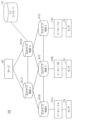
- FIG. 2 shows an example of the configuration of a communication network 80.
- the communication network 80 is composed of multiple network devices 81.
- the network devices 81 used between the data source 10 and the server 40 are determined in advance.
- the data source 10A and the server 40 are connected by network devices 81A and 81B
- the data source 10B and the server 40 are connected by network devices 81A and 81C
- the data source 10C and the server 40 are connected by network devices 81D and 81E.
- each of network devices 81A-81E When each of network devices 81A-81E receives data addressed to server 40 from data sources 10A-10C, it knows which network device to transfer the data to. Therefore, even if data sources 10A-10C do not know which network device 81 to use, if they send data by specifying server 40, the data will be sent to server 40. As a result, the present disclosure is capable of transferring data losslessly and at a wide bandwidth when a communication path is established.
- FIG. 3 shows an example of the configuration of the data source 10.
- the data source 10 is a device that has sensing data from the user side.
- the data source 10 includes, for example, a data transmission/reception unit 11, a calculation processing unit 12, and a storage unit 13.
- the calculation processing unit 12 acquires sensing data from an arbitrary sensor 50 and stores it in the storage unit 13.
- the data transmission/reception unit 11 transmits the sensing data to the server 40.
- the data transmission/reception unit 11 transmits and receives arbitrary information to and from the server 40, and also transmits and receives arbitrary information to and from the path controller 30.
- the communication method such as the communication network and communication standard, may be the same for the server 40 and the path controller 30, or may be different.
- the storage unit 13 may store a transmission policy that determines the timing of transmitting the sensing data. In this case, the data transmission/reception unit 11 transmits the sensing data according to the transmission policy.
- FIG. 4 shows an example of the configuration of the server 40.
- the server 40 is a device that collects various data, including sensing data, from the data source 10.
- the server 40 includes, for example, a data transmission/reception unit 41, a calculation processing unit 42, and a storage unit 43.
- the data transmission/reception unit 41 receives sensing data from any data source 10.
- the calculation processing unit 42 acquires the sensing data of any data source 10 and stores it in the storage unit 43.
- the data transmission/reception unit 41 transmits and receives arbitrary information to and from the data source 10, and also transmits and receives arbitrary information to and from the path controller 30.
- the communication method such as the communication network and communication standard, may be the same for the data source 10 and the path controller 30, or may be different.
- FIG. 5 shows an example of the configuration of the path controller 30.
- the path controller 30 is a device that controls a communication path and can establish a communication path from the data source 10 to the server 40.
- the path controller 30 includes, for example, a path setting control unit 31, a path setting unit 32, and a path setting location table 33.
- the path setting location table 33 stores information on the network devices 81 that transfer the sensing data from each data source 10.
- the path setting control unit 31 determines the network device 81 to be used for the communication path connecting the data source 10 and the server 40 based on the path setting location table 33, and controls the setting of the network device 81.
- the path setting unit 32 sets the network device 81 according to instructions from the path setting control unit 31. As a result, a communication path connecting the data source 10 and the server 40 is established.
- FIG. 6 shows an example of the path setting location table 33.
- the information of the network device 81 includes identification information of the network devices 81A and 81B that connect the data source 10A and the server 40, and setting information (establishment/release) of the communication paths in the network devices 81A and 81B.
- the path setting control unit 31 transmits and receives arbitrary information to and from the data source 10, and also transmits and receives arbitrary information to and from the server 40.
- the communication method such as the communication network and communication standard, may be the same for the data source 10 and the server 40, or may be different.
- FIG. 7 shows an example of a sensing data transmission sequence when the path linkage RDMA method is used.
- the data source 10B transmits a request for establishing a communication path to the path controller 30 (S101).
- the path controller 30 receives the request to establish a communication path, it sets the communication path between the network devices 81A and 81C and establishes the communication path (S102).
- the path controller 30 transmits a communication path establishment completion notification to the data source 10B (S103).
- the data source 10B receives the notification that the communication path has been established, it transmits sensing data to the server 40 (S104).
- the data source 10B When the data source 10B has completed transmitting the sensing data to the server 40, it transmits a communication path release request to the path controller 30 (S105).
- the path controller 30 receives the communication path release request, it releases the communication paths of the network devices 81A and 81C, and transmits a communication path release completion notification to the data source 10B to the effect that the communication path release has been completed (S106).
- the path controller 30 receives the communication path release request, it releases the communication paths of the network devices 81A and 81C, and transmits a communication path release completion notification to the data source 10B indicating that the communication path release has been completed.
- the sequence shown in FIG. 7 is an example of a transmission policy in which a communication path is established immediately after data is generated and data is transferred, but there are other transmission policies as well, such as a transmission policy in which data is transferred after a certain amount of data has accumulated, or a transmission policy in which data is transferred at a predetermined time.
- This disclosure is applicable to any transmission policy.
- the path linkage RDMA method When the path linkage RDMA method is used for data transfer from the data source 10 to the server 40, the load of the reception process on the server 40 is small, but the network efficiency of the communication network 80 decreases. On the other hand, if the TCP method is used for data transfer from the data source 10 to the server 40, the network efficiency of the communication network 80 does not decrease, but the CPU load of the server 40 increases due to reception processing.
- the data source 10 is made capable of transmitting data using both the path linkage RDMA method (first communication method) and the TCP method (second communication method)
- the server 40 is made capable of receiving data using both the path linkage RDMA method (first communication method) and the TCP method (second communication method)
- the method of transferring data from the data source 10 to the server 40 is selected based on the status of the communication network 80.
- the path controller 30 establishes a communication path between the data source 10 and the server 40. Therefore, in this disclosure, the path controller 30 acquires the status of the communication network 80 and selects a data transfer method based on the status of the communication network 80. A specific explanation is given below.
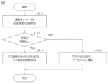
- FIG. 8 An example of the selection of the data transfer method in this embodiment is shown in Fig. 8.
- the state of the communication network 80 is the delay time of the communication network 80, and the TCP method is selected within a range that satisfies the delay requirement of the sensing data.
- the path controller 30 acquires the delay time from the data source 10 to the server 40 (S111).
- the timing for acquiring the delay time is arbitrary, but may be periodically, for example.
- the delay time acquired by the path controller 30 is not limited to the delay time from the data source 10 to the server 40, but may be the delay time of any section of the communication network 80 that can predict the delay time from the data source 10 to the server 40, such as the delay time from the path controller 30 to the server 40.
- the path controller 30 judges whether the delay time is equal to or greater than a threshold value (S112). If the delay time is less than the threshold value (No in S112), the TCP method is selected, and the use of the TCP method is notified to the data source 10 (S113). If the delay time is equal to or greater than the threshold (Yes in S112), the path linkage RDMA method is selected (S114), and the use of the path linkage RDMA method is notified to the data source 10. This causes the data source 10 to wait for the establishment of a communication path.
- Each data source 10 uses the notified method when transmitting data to the server 40. Specifically, if the data source 10 has been notified of the TCP method, it transmits data from the data source 10 to the server 40 using the TCP method. If the data source 10 has been notified of the path linkage RDMA method, it transmits data from the data source 10 to the server 40 using the path linkage RDMA method.
- the threshold in step S112 can be determined based on the delay requirements of the sensing data. For example, if the sensing data is video data at 60 FPS (frames per second), the TCP method is selected if the delay time between the data source 10 and the server 40 is less than 16 ms, and the path linkage RDMA method is selected if the delay time is 16 ms or more. In this way, this embodiment can adopt any threshold value according to the delay requirements of the sensing data. This makes it possible to improve network efficiency while satisfying the delay requirements of the sensing data.
- the TCP method is selected as long as the delay time of the communication network 80 is consistent with the transmission policy of the sensing data, and the path linkage RDMA method is selected when the TCP method no longer satisfies the delay requirements of the sensing data. This makes it possible to improve the network efficiency of the communication network 80.
- the path controller 30 may execute step S112 when transmitting data from the data source 10 to the server 40. For example, when receiving a request to establish a communication path as shown in step S101 of FIG. 7. In this case, the path controller 30 can establish a communication path when executing step S114.
- the path controller 30 may execute steps S111 and S112 at the predetermined time.
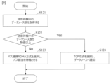
- Second Embodiment 9 shows an example of a data transfer method selection in this embodiment.
- the status of the communication network 80 is the number of data sources waiting to transmit data, and the path linkage RDMA method is selected within a range determined by the number of data sources waiting to transmit data.
- the path controller 30 acquires the number of data sources waiting to transmit data (S121).
- the timing for acquiring the number of data sources is arbitrary, but may be performed periodically, for example.
- the number of data sources waiting to transmit data is, for example, the number of data sources 10 that have received a request to establish a communication path and to which a communication path has not yet been assigned.
- the path controller 30 judges whether the number of data sources is equal to or greater than a threshold value (S122). If the number of data sources is less than the threshold value (No in S122), the path controller 30 selects the path linkage RDMA method and notifies the data source 10 of the use of the path linkage RDMA method (S123). This causes the data source 10 to wait for the communication path to be established. If the number of data sources is equal to or greater than the threshold value (Yes in S122), the path controller 30 selects the TCP method and notifies the data source 10 that the TCP method will be used (S124).
- each data source 10 uses the notified method when transmitting data to the server 40.
- the threshold value in step S122 can be determined based on the upper limit of the number of data sources to which a communication path can be assigned in the communication network 80. In addition, in order to determine whether a communication path can be assigned immediately, the average allocation time of the communication path can be obtained separately, and the probability that a communication path will be assigned within a predetermined time if there is waiting can be set as the threshold value.
- the threshold in this embodiment can use any information that represents the load on the communication network 80 by the path linkage RDMA method, for example, the following can be exemplified.
- Amount of data waiting to be transmitted Number of data sources to which communication paths have already been assigned Bandwidth already used to establish communication paths
- Percentage of available bandwidth predetermined for the communication network 80 that is used to establish communication paths Time required for a communication path to be assigned Probability of a communication path being assigned within a predetermined time
- the TCP method when there is a possibility of affecting the network efficiency of the communication network 80, the TCP method is used to prevent any impact on the network efficiency of the communication network 80.
- the load on the server 40 can be reduced by transmitting data using the path linkage RDMA method within the range that satisfies the network efficiency of the communication network 80.
- the timing at which the path controller 30 executes step S122 and the timing at which the path controller 30 obtains the number of data sources waiting to transmit data in step S121 are the same as in the first embodiment.
- this embodiment selectively uses the path linkage RDMA method and the TCP method based on the load on the communication network 80 caused by the path linkage RDMA method. This allows this embodiment to adjust the balance between the server load and the network load.
- the path linkage RDMA method and the TCP method are used differently based on the load on the network 80, but the path linkage RDMA method and the TCP method may also be used differently based on the resources available in the network 80. In this case, it is determined that a communication path is to be established when the resources are equal to or greater than a threshold, and it is determined that a communication path is not to be established when the resources are less than the threshold.
- Third Embodiment 10 shows an example of the selection of the data transfer method of this embodiment.
- the status of the communication network 80 is both the delay time of the communication network 80 and the number of data sources waiting to transmit data, and the path linkage RDMA method and the TCP method are used depending on both of these.
- the controller 30 obtains the number of data sources waiting to transmit data (S131), and determines whether the number of data sources is equal to or greater than a threshold value (S132). If the number of data sources is less than the threshold value (No in S132), the path controller 30 acquires the delay time from the data source 10 to the server 40 (S133), and judges whether the delay time is equal to or greater than the threshold value (S134).
- the path association RDMA method is selected and path allocation is put on hold (S135). If the number of data sources is equal to or greater than the threshold (Yes in S132), or if the delay time is equal to or greater than the threshold (No in S134), the path controller 30 selects the TCP method and notifies the data source 10 of this (S136).
- the threshold value in step S132 is the same as in the second embodiment, and the threshold value in step S134 is the same as in the first embodiment.
- this embodiment selectively uses the path linkage RDMA method and the TCP method based on both the number of data sources waiting to transmit data and the delay time of the communication network 80, thereby maintaining the load balance of the communication network 80.
- both the path linkage RDMA method and the TCP method may be used.
- the path controller 30 adjusts the ratio of the path linkage RDMA method and the TCP method based on at least one of the delay time of the communication network 80 and the number of data sources waiting to transmit data.
- the controller 30 can mix a data source that uses the path linkage RDMA method (data source A) and a data source that uses the TCP method (data source B) by changing the frequency of judgment using a flowchart similar to that of the first and second embodiments.
- the data source 10 may obtain the delay time of the communication network 80 and select the data transfer method based on this. In this case, the data source 10 may send a request to establish a communication path to the controller 30 only when the path linkage RDMA method is selected.
- the present embodiment shows an example in which the path linkage RDMA method and the TCP method are used interchangeably, the present disclosure is not limited to this.
- any communication method that establishes a communication path may be adopted in place of the path linkage RDMA method or in addition to the path linkage RDMA method.
- any communication method that does not establish a communication path may be adopted in place of the TCP method or in addition to the TCP method.
- the present disclosure selects a transfer method based on the status of the communication network 80, such as the delay time and the load on the communication network 80 due to the path linkage RDMA method. This makes it possible for the present disclosure to adjust the server load and network efficiency.
- the path controller 30 may selectively use the path linkage RDMA method and the TCP method based on the status of the server 40 in addition to the status of the communication network 80. For example, the path controller 30 may determine the memory load or CPU load of the server 40.
- 10A, 10B, 10C Data source 11, 41: Data transmission/reception unit 12, 42: Processing unit 13, 43: Storage unit 30: Path controller 31: Path setting control unit 32: Path setting unit 33: Path setting location table 40: Server 50: Sensor 80: Communication network 81A, 81B, 81C, 81D, 81E: Network equipment
Landscapes
- Engineering & Computer Science (AREA)
- Computer Security & Cryptography (AREA)
- Computer Networks & Wireless Communication (AREA)
- Signal Processing (AREA)
- Data Exchanges In Wide-Area Networks (AREA)
Priority Applications (2)
| Application Number | Priority Date | Filing Date | Title |
|---|---|---|---|
| JP2024569882A JPWO2024150300A1 (https=) | 2023-01-11 | 2023-01-11 | |
| PCT/JP2023/000395 WO2024150300A1 (ja) | 2023-01-11 | 2023-01-11 | 通信ネットワークの状況に応じた方法でデータを転送する装置及び方法 |
Applications Claiming Priority (1)
| Application Number | Priority Date | Filing Date | Title |
|---|---|---|---|
| PCT/JP2023/000395 WO2024150300A1 (ja) | 2023-01-11 | 2023-01-11 | 通信ネットワークの状況に応じた方法でデータを転送する装置及び方法 |
Publications (1)
| Publication Number | Publication Date |
|---|---|
| WO2024150300A1 true WO2024150300A1 (ja) | 2024-07-18 |
Family
ID=91896603
Family Applications (1)
| Application Number | Title | Priority Date | Filing Date |
|---|---|---|---|
| PCT/JP2023/000395 Ceased WO2024150300A1 (ja) | 2023-01-11 | 2023-01-11 | 通信ネットワークの状況に応じた方法でデータを転送する装置及び方法 |
Country Status (2)
| Country | Link |
|---|---|
| JP (1) | JPWO2024150300A1 (https=) |
| WO (1) | WO2024150300A1 (https=) |
Citations (5)
| Publication number | Priority date | Publication date | Assignee | Title |
|---|---|---|---|---|
| JPH11355273A (ja) * | 1998-06-05 | 1999-12-24 | Nec Corp | ネットワーク管理システムにおけるudpによる通知データの保証システム及び方法 |
| JP2004032039A (ja) * | 2002-06-21 | 2004-01-29 | Ricoh Co Ltd | ネットワークファクシミリ装置およびファクシミリ送信システム |
| JP2004260789A (ja) * | 2003-02-04 | 2004-09-16 | Hitachi Kokusai Electric Inc | パケット通信装置 |
| JP2007081651A (ja) * | 2005-09-13 | 2007-03-29 | Fuji Xerox Co Ltd | 画像データの転送方法及び画像処理装置 |
| JP2017517922A (ja) * | 2014-04-10 | 2017-06-29 | クアルコム,インコーポレイテッド | リアルタイムトランスポートプロトコルのためのストリーミング制御 |
Family Cites Families (1)
| Publication number | Priority date | Publication date | Assignee | Title |
|---|---|---|---|---|
| JP7331500B2 (ja) * | 2019-06-28 | 2023-08-23 | コニカミノルタ株式会社 | 画像形成装置及びデータ転送方法 |
-
2023
- 2023-01-11 JP JP2024569882A patent/JPWO2024150300A1/ja active Pending
- 2023-01-11 WO PCT/JP2023/000395 patent/WO2024150300A1/ja not_active Ceased
Patent Citations (5)
| Publication number | Priority date | Publication date | Assignee | Title |
|---|---|---|---|---|
| JPH11355273A (ja) * | 1998-06-05 | 1999-12-24 | Nec Corp | ネットワーク管理システムにおけるudpによる通知データの保証システム及び方法 |
| JP2004032039A (ja) * | 2002-06-21 | 2004-01-29 | Ricoh Co Ltd | ネットワークファクシミリ装置およびファクシミリ送信システム |
| JP2004260789A (ja) * | 2003-02-04 | 2004-09-16 | Hitachi Kokusai Electric Inc | パケット通信装置 |
| JP2007081651A (ja) * | 2005-09-13 | 2007-03-29 | Fuji Xerox Co Ltd | 画像データの転送方法及び画像処理装置 |
| JP2017517922A (ja) * | 2014-04-10 | 2017-06-29 | クアルコム,インコーポレイテッド | リアルタイムトランスポートプロトコルのためのストリーミング制御 |
Also Published As
| Publication number | Publication date |
|---|---|
| JPWO2024150300A1 (https=) | 2024-07-18 |
Similar Documents
| Publication | Publication Date | Title |
|---|---|---|
| US12369074B2 (en) | Data packet sending method and apparatus | |
| JP6931041B2 (ja) | グラントフリー伝送のためのアップリンクデータスケジューリングのための方法、ユーザ機器、非一時的記憶媒体、およびプログラム | |
| US20150237525A1 (en) | Traffic Shaping and Steering for a Multipath Transmission Control Protocol Connection | |
| JP2009544259A (ja) | 無線通信システムにおけるポリシー施行のための方法及び装置 | |
| WO2020140729A1 (zh) | 数据传输方法、装置、计算机可读介质及电子设备 | |
| JP2008099286A (ja) | 無線メッシュネットワークにおいてデータフロー制御をサポートする方法および装置 | |
| US20200252337A1 (en) | Data transmission method, device, and computer storage medium | |
| WO2018113393A1 (zh) | 报文传输方法及混合接入网关 | |
| WO2012126333A1 (zh) | 物联网通信方法、网关、终端及系统 | |
| US20220248259A1 (en) | Data processing method and apparatus | |
| WO2011006336A1 (zh) | 一种基于tdd制式的数据传输方法和装置 | |
| KR102111029B1 (ko) | 다중망 병합 전송 장치, 그리고 이의 패킷 스케줄링 방법 | |
| JP2005323373A (ja) | 無線ローカル・エリア・ネットワークにおける動的チャネル割り当て | |
| US10439945B2 (en) | Single stream aggregation protocol | |
| WO2024150300A1 (ja) | 通信ネットワークの状況に応じた方法でデータを転送する装置及び方法 | |
| WO2024150297A1 (ja) | サーバの状況に応じた方法でデータを転送する装置及び方法 | |
| NO327367B1 (no) | Tildeling av tradlose kanaler i en basestasjonsprosessor | |
| JP6856521B2 (ja) | 通信装置、通信システム及びプログラム | |
| JP7816577B2 (ja) | 通信パスの確立を事前に予測して実行する装置及び方法 | |
| JP7831649B2 (ja) | 通信パスの解放を事前に予測して実行する装置及び方法 | |
| JP7704287B2 (ja) | データを収集するシステム、方法及びプログラム | |
| JP7695635B2 (ja) | データを収集するシステム、方法及びプログラム | |
| CN111345111B (zh) | 用于处理数据到无线设备的无线电通信的方法和设备代理 | |
| JP7704286B2 (ja) | データを収集するシステム、方法及びプログラム | |
| JP2017135641A (ja) | 無線通信装置、方法及びプログラム |
Legal Events
| Date | Code | Title | Description |
|---|---|---|---|
| 121 | Ep: the epo has been informed by wipo that ep was designated in this application |
Ref document number: 23915924 Country of ref document: EP Kind code of ref document: A1 |
|
| WWE | Wipo information: entry into national phase |
Ref document number: 2024569882 Country of ref document: JP |
|
| NENP | Non-entry into the national phase |
Ref country code: DE |
|
| 122 | Ep: pct application non-entry in european phase |
Ref document number: 23915924 Country of ref document: EP Kind code of ref document: A1 |