WO2024147196A1 - 自動車 - Google Patents
自動車 Download PDFInfo
- Publication number
- WO2024147196A1 WO2024147196A1 PCT/JP2023/000188 JP2023000188W WO2024147196A1 WO 2024147196 A1 WO2024147196 A1 WO 2024147196A1 JP 2023000188 W JP2023000188 W JP 2023000188W WO 2024147196 A1 WO2024147196 A1 WO 2024147196A1
- Authority
- WO
- WIPO (PCT)
- Prior art keywords
- engine
- bracket
- mount
- supported
- mount bracket
- Prior art date
- Legal status (The legal status is an assumption and is not a legal conclusion. Google has not performed a legal analysis and makes no representation as to the accuracy of the status listed.)
- Ceased
Links
Images


Classifications
-
- B—PERFORMING OPERATIONS; TRANSPORTING
- B62—LAND VEHICLES FOR TRAVELLING OTHERWISE THAN ON RAILS
- B62D—MOTOR VEHICLES; TRAILERS
- B62D21/00—Understructures, i.e. chassis frame on which a vehicle body may be mounted
- B62D21/02—Understructures, i.e. chassis frame on which a vehicle body may be mounted comprising longitudinally or transversely arranged frame members
-
- B—PERFORMING OPERATIONS; TRANSPORTING
- B60—VEHICLES IN GENERAL
- B60K—ARRANGEMENT OR MOUNTING OF PROPULSION UNITS OR OF TRANSMISSIONS IN VEHICLES; ARRANGEMENT OR MOUNTING OF PLURAL DIVERSE PRIME-MOVERS IN VEHICLES; AUXILIARY DRIVES FOR VEHICLES; INSTRUMENTATION OR DASHBOARDS FOR VEHICLES; ARRANGEMENTS IN CONNECTION WITH COOLING, AIR INTAKE, GAS EXHAUST OR FUEL SUPPLY OF PROPULSION UNITS IN VEHICLES
- B60K5/00—Arrangement or mounting of internal-combustion or jet-propulsion units
- B60K5/02—Arrangement or mounting of internal-combustion or jet-propulsion units with the engine main axis, e.g. crankshaft axis, substantially in or parallel to the longitudinal centre line of the vehicle
-
- B—PERFORMING OPERATIONS; TRANSPORTING
- B60—VEHICLES IN GENERAL
- B60K—ARRANGEMENT OR MOUNTING OF PROPULSION UNITS OR OF TRANSMISSIONS IN VEHICLES; ARRANGEMENT OR MOUNTING OF PLURAL DIVERSE PRIME-MOVERS IN VEHICLES; AUXILIARY DRIVES FOR VEHICLES; INSTRUMENTATION OR DASHBOARDS FOR VEHICLES; ARRANGEMENTS IN CONNECTION WITH COOLING, AIR INTAKE, GAS EXHAUST OR FUEL SUPPLY OF PROPULSION UNITS IN VEHICLES
- B60K5/00—Arrangement or mounting of internal-combustion or jet-propulsion units
- B60K5/12—Arrangement of engine supports
- B60K5/1208—Resilient supports
- B60K5/1216—Resilient supports characterised by the location of the supports relative to the motor or to each other
-
- B—PERFORMING OPERATIONS; TRANSPORTING
- B60—VEHICLES IN GENERAL
- B60K—ARRANGEMENT OR MOUNTING OF PROPULSION UNITS OR OF TRANSMISSIONS IN VEHICLES; ARRANGEMENT OR MOUNTING OF PLURAL DIVERSE PRIME-MOVERS IN VEHICLES; AUXILIARY DRIVES FOR VEHICLES; INSTRUMENTATION OR DASHBOARDS FOR VEHICLES; ARRANGEMENTS IN CONNECTION WITH COOLING, AIR INTAKE, GAS EXHAUST OR FUEL SUPPLY OF PROPULSION UNITS IN VEHICLES
- B60K5/00—Arrangement or mounting of internal-combustion or jet-propulsion units
- B60K5/12—Arrangement of engine supports
- B60K5/1241—Link-type support
-
- B—PERFORMING OPERATIONS; TRANSPORTING
- B62—LAND VEHICLES FOR TRAVELLING OTHERWISE THAN ON RAILS
- B62D—MOTOR VEHICLES; TRAILERS
- B62D21/00—Understructures, i.e. chassis frame on which a vehicle body may be mounted
- B62D21/09—Means for mounting load bearing surfaces
-
- B—PERFORMING OPERATIONS; TRANSPORTING
- B62—LAND VEHICLES FOR TRAVELLING OTHERWISE THAN ON RAILS
- B62D—MOTOR VEHICLES; TRAILERS
- B62D21/00—Understructures, i.e. chassis frame on which a vehicle body may be mounted
- B62D21/11—Understructures, i.e. chassis frame on which a vehicle body may be mounted with resilient means for suspension, e.g. of wheels or engine; sub-frames for mounting engine or suspensions
-
- B—PERFORMING OPERATIONS; TRANSPORTING
- B60—VEHICLES IN GENERAL
- B60K—ARRANGEMENT OR MOUNTING OF PROPULSION UNITS OR OF TRANSMISSIONS IN VEHICLES; ARRANGEMENT OR MOUNTING OF PLURAL DIVERSE PRIME-MOVERS IN VEHICLES; AUXILIARY DRIVES FOR VEHICLES; INSTRUMENTATION OR DASHBOARDS FOR VEHICLES; ARRANGEMENTS IN CONNECTION WITH COOLING, AIR INTAKE, GAS EXHAUST OR FUEL SUPPLY OF PROPULSION UNITS IN VEHICLES
- B60K5/00—Arrangement or mounting of internal-combustion or jet-propulsion units
- B60K2005/003—Arrangement or mounting of internal-combustion or jet-propulsion units the internal combustion or jet propulsion unit is arranged between the front and the rear axle
Definitions
- the present invention relates to automobiles, and in particular to a mounting structure for a front differential gear unit to a chassis frame.
- Patent Document 1 In a four-wheel drive automobile equipped with a chassis frame, a front differential gear unit is known that is elastically supported on the chassis frame at three points (Patent Document 1).
- the left front mount of the front differential gear unit is supported on the second cross member of the chassis frame, and the right front mount and rear mount are supported on the third cross member (see [0058] and Figure 20 of Patent Document 1, etc.).
- the left front mount of the front differential gear unit is supported by the second cross member of the chassis frame, which creates the problem that in the event of a full-wrap frontal collision, the side member is crushed between the second and third cross members, and no space is provided to absorb the collision energy.
- the problem that this invention aims to solve is to provide a vehicle in which the side members can collapse to provide space to absorb the collision energy during a frontal collision.
- the present invention solves the above problem by using a side member of the chassis frame to support the front mount portion of the front differential gear unit at a position that overlaps the engine mount bracket in a plan view.
- a space can be secured behind the adjacent cross member on the front side of the engine mount bracket in which the side member can collapse and absorb the collision energy during a frontal collision.
- FIG. 1 is a side view showing an entire automobile according to an embodiment of the present invention
- FIG. 2 is a plan view showing the chassis frame of FIG. 1
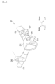
- 1 is a perspective view showing a main portion of a front differential gear unit according to an embodiment of the present invention
- FIG. 4 is a plan view showing a mounting structure of the front differential gear unit of FIG. 3 to a chassis frame.
- 5 is a view taken along the arrow V in FIG. 4 , showing the left front mounting bracket according to the embodiment of the present invention.
- FIG. 5B is an exploded perspective view of the left front mounting bracket of FIG. 5A.
- 6 is a view taken along the arrow VI in FIG. 4 , showing a right-side front mounting bracket according to one embodiment of the present invention.
- FIG. 1 is a side view showing an entire automobile according to an embodiment of the present invention
- FIG. 2 is a plan view showing the chassis frame of FIG. 1.
- the automobile V of this embodiment is a chassis frame type vehicle, and is a front engine, four-wheel drive automobile.
- the automobile V of this embodiment has a chassis frame 1 and an upper body B fixed to this chassis frame 1, and the engine E, transmission T, and a suspension system (not shown) including wheels W are mounted on the chassis frame 1.
- the upper body B including the engine room B1 and cabin B2 is attached via elastic bodies to a plurality of cab mount brackets 12 (see FIG. 2) provided on a side member 11 of the chassis frame 1, whereby the upper body B is mounted on the chassis frame 1.
- the chassis frame 1 of this embodiment comprises a pair of left and right side members 11, 11 and a number of cross members 13. Both the side members 11 and the cross members 13 are formed by processing steel plates or other metal plates, and are formed into a frame having a closed cross section, for example, by combining the plate materials and joining them by welding or the like. As shown in FIG. 1, each side member 11 extends from the front end to the rear end of the automobile V, and as shown in FIG.
- a first cross member 131, a second cross member 132, a third cross member 133, a fourth cross member 134, a fifth cross member 135, a sixth cross member 136, a seventh cross member 137, an eighth cross member 138, and a ninth cross member 139 are spanned between the pair of side members 11, 11 from the front end to the rear end.
- the side members 11 and each cross member 13 are firmly joined by welding or the like, making the chassis frame 1 of this embodiment a sturdy skeletal component capable of supporting the power train including the engine E and transmission T, the suspension parts including the wheels W, and the upper body B.
- the reference numeral 14 denotes a suspension tower to which the springs of the suspension system are attached.
- the engine E of this embodiment is supported by engine mount brackets 15, 15 provided on the left and right side members 11, 11 between the third cross member 133 and the fourth cross member 134.
- the transmission T attached to the engine E is supported by the fifth cross member 135. Since the automobile of this embodiment is a front-engine, four-wheel-drive vehicle, the transmission T is connected to a rear differential gear unit (not shown) that transmits the driving force of the engine E to the rear wheels W, as well as a front differential gear unit D that transmits the driving force of the engine E to the front wheels W.
- FIG 3 is a perspective view showing the main parts of the front differential gear unit D according to this embodiment.
- the front differential gear unit D of this embodiment has a casing D1 that houses a differential gear (not shown), and the input side of this differential gear is connected to a drive shaft D2 that is connected to the output shaft of the transmission T, and the input rotation of the drive shaft D2 is output to the left front wheel drive shaft D3 and the right front wheel drive shaft D4 by the differential gear.
- the front differential gear unit D of this embodiment is mounted on the left side of the engine E, so that a left front mount part D5 and a right front mount part D6 are provided on the front side of the casing D1, and a rear mount part D7 is provided on the rear side of the casing D1.
- FIG. 4 is a plan view showing the mounting structure of the front differential gear unit D shown in FIG. 3 to the chassis frame 1, and is an enlarged plan view of the portion between the third cross member 133 and the fourth cross member 134 in FIG. 2.
- the front differential gear unit D of this embodiment is supported by the chassis frame 1 at three points as shown in FIG. 4. That is, the left front mount part D5 is attached to the left front mount bracket 16 fixed to the left side member 11, and the right front mount part D6 is attached to the right front mount bracket 17 fixed to the right side member 11.
- the rear mount part D7 is attached to the rear mount bracket 18 fixed to the adjacent fourth cross member 134 on the rear side of the engine mount bracket 15.
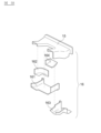
- Figure 5A shows the left front mounting bracket 16 according to one embodiment of the present invention, as viewed from the V arrow in Figure 4, and Figure 5B is an exploded perspective view thereof.
- Figure 6A shows the right front mounting bracket 17 according to one embodiment of the present invention, as viewed from the VI arrow in Figure 4, and Figure 6B is an exploded perspective view thereof.
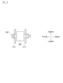
- Figure 7 is a cross-sectional view taken along line VII-VII in Figure 5A
- Figure 8 is a cross-sectional view taken along line VIII-VIII in Figure 6A.
- a fastener 165 is inserted into the left front mount part D5 of the front differential gear unit D, and the fastener 165 is fastened with a bolt 166 to the left front mount bracket 16, which has two closed cross sections, so that the left front mount part D5 is supported by the side member 11. Since an elastic body is provided in the left front mount part D5, the front differential gear unit D is elastically supported by the side member 11.
- the work of attaching the left front mount part D5 to the left front mount bracket 16 is the work of fastening the bolt 166 from the bottom to the top of the vehicle, so that the tightening work can be performed without the tightening tool for the bolt 166 interfering with other parts.
- the subassembly components of the engine mount bracket 15 and right front mount bracket 17 have a structure that includes two closed cross sections, as shown in FIG. 6A, ensuring the strength necessary to support the engine E and front differential gear unit D.
- a bolt 167 is inserted into the right front mount part D6 of the front differential gear unit D and tightened with a nut, so that the right front mount part D6 is supported by the side member 11.
- an elastic body is provided in the right front mount part D6, so that the front differential gear unit D is elastically supported by the side member 11.
- the front differential gear unit D further has a rear mount portion D7, which is supported by the adjacent fourth cross member 134, among the multiple cross members 131 to 139, at the rear side of the engine mount bracket 15. This allows a space S to be secured behind the third cross member 133, and in the event of a frontal collision, the side member is crushed in this space S, allowing the collision energy to be absorbed.
- the left front mount part D5 of the front differential gear unit D is supported by the lower part of the left engine mount bracket 15 of the left side member 11. This allows a space S to be secured behind the third cross member 133, and in the event of a frontal collision, the side member is crushed in this space S, allowing the collision energy to be absorbed.
Landscapes
- Engineering & Computer Science (AREA)
- Chemical & Material Sciences (AREA)
- Combustion & Propulsion (AREA)
- Transportation (AREA)
- Mechanical Engineering (AREA)
- Body Structure For Vehicles (AREA)
Priority Applications (4)
| Application Number | Priority Date | Filing Date | Title |
|---|---|---|---|
| PCT/JP2023/000188 WO2024147196A1 (ja) | 2023-01-06 | 2023-01-06 | 自動車 |
| CN202380090293.4A CN120476073A (zh) | 2023-01-06 | 2023-01-06 | 汽车 |
| JP2024568683A JPWO2024147196A1 (https=) | 2023-01-06 | 2023-01-06 | |
| EP23914687.1A EP4647321A4 (en) | 2023-01-06 | 2023-01-06 | MOTOR VEHICLE |
Applications Claiming Priority (1)
| Application Number | Priority Date | Filing Date | Title |
|---|---|---|---|
| PCT/JP2023/000188 WO2024147196A1 (ja) | 2023-01-06 | 2023-01-06 | 自動車 |
Publications (1)
| Publication Number | Publication Date |
|---|---|
| WO2024147196A1 true WO2024147196A1 (ja) | 2024-07-11 |
Family
ID=91803715
Family Applications (1)
| Application Number | Title | Priority Date | Filing Date |
|---|---|---|---|
| PCT/JP2023/000188 Ceased WO2024147196A1 (ja) | 2023-01-06 | 2023-01-06 | 自動車 |
Country Status (4)
| Country | Link |
|---|---|
| EP (1) | EP4647321A4 (https=) |
| JP (1) | JPWO2024147196A1 (https=) |
| CN (1) | CN120476073A (https=) |
| WO (1) | WO2024147196A1 (https=) |
Citations (5)
| Publication number | Priority date | Publication date | Assignee | Title |
|---|---|---|---|---|
| JPH04118325A (ja) * | 1990-09-08 | 1992-04-20 | Mazda Motor Corp | エンジンの支持装置 |
| JP2004330855A (ja) * | 2003-05-07 | 2004-11-25 | Honda Motor Co Ltd | 後部車体構造 |
| JP2004345466A (ja) * | 2003-05-21 | 2004-12-09 | Nissan Motor Co Ltd | 車体前部骨格構造 |
| JP2008132852A (ja) * | 2006-11-28 | 2008-06-12 | Nissan Motor Co Ltd | 車両用駆動ユニットの防振支持構造 |
| WO2011101906A1 (ja) | 2010-02-18 | 2011-08-25 | フォード グローバル テクノロジーズ、リミテッド ライアビリティ カンパニー | 車両の前面衝突エネルギー吸収構造 |
Family Cites Families (2)
| Publication number | Priority date | Publication date | Assignee | Title |
|---|---|---|---|---|
| US8641066B2 (en) * | 2011-03-18 | 2014-02-04 | Honda Motor Co., Ltd. | Integrated suspension and differential mounting structure |
| JP7124736B2 (ja) * | 2019-01-30 | 2022-08-24 | トヨタ自動車株式会社 | シリーズハイブリッド車両における駆動装置の搭載構造 |
-
2023
- 2023-01-06 WO PCT/JP2023/000188 patent/WO2024147196A1/ja not_active Ceased
- 2023-01-06 JP JP2024568683A patent/JPWO2024147196A1/ja active Pending
- 2023-01-06 EP EP23914687.1A patent/EP4647321A4/en not_active Withdrawn
- 2023-01-06 CN CN202380090293.4A patent/CN120476073A/zh active Pending
Patent Citations (5)
| Publication number | Priority date | Publication date | Assignee | Title |
|---|---|---|---|---|
| JPH04118325A (ja) * | 1990-09-08 | 1992-04-20 | Mazda Motor Corp | エンジンの支持装置 |
| JP2004330855A (ja) * | 2003-05-07 | 2004-11-25 | Honda Motor Co Ltd | 後部車体構造 |
| JP2004345466A (ja) * | 2003-05-21 | 2004-12-09 | Nissan Motor Co Ltd | 車体前部骨格構造 |
| JP2008132852A (ja) * | 2006-11-28 | 2008-06-12 | Nissan Motor Co Ltd | 車両用駆動ユニットの防振支持構造 |
| WO2011101906A1 (ja) | 2010-02-18 | 2011-08-25 | フォード グローバル テクノロジーズ、リミテッド ライアビリティ カンパニー | 車両の前面衝突エネルギー吸収構造 |
Non-Patent Citations (1)
| Title |
|---|
| See also references of EP4647321A1 |
Also Published As
| Publication number | Publication date |
|---|---|
| CN120476073A (zh) | 2025-08-12 |
| JPWO2024147196A1 (https=) | 2024-07-11 |
| EP4647321A4 (en) | 2026-03-11 |
| EP4647321A1 (en) | 2025-11-12 |
Similar Documents
| Publication | Publication Date | Title |
|---|---|---|
| US9045170B2 (en) | Rear-wheel drive, plug-in hybrid electric vehicle modular subframe assembly and method | |
| JP4802783B2 (ja) | 車体前部構造 | |
| JP6725070B2 (ja) | 車両の後部車体構造 | |
| JP5029135B2 (ja) | 自動車の側部車体構造 | |
| US20160068195A1 (en) | Battery arrangement in a two-track vehicle | |
| US12220979B2 (en) | Support device for vehicle battery pack and electric vehicle | |
| US20100026051A1 (en) | Vehicle front structure | |
| US4840424A (en) | Automotive rear underbody structure | |
| WO2013094190A1 (ja) | 自動車のフロントサブフレーム構造 | |
| WO2013080340A1 (ja) | 車体構造 | |
| JP2005510405A (ja) | 自動車用モジュラー車台 | |
| WO2017163307A1 (ja) | 車体下部構造 | |
| CN110121441A (zh) | 马达驱动装置 | |
| US11235809B2 (en) | Vehicle body for vehicles | |
| WO2024147196A1 (ja) | 自動車 | |
| US11964696B2 (en) | Structural frame for the body of a motor vehicle | |
| JP4432672B2 (ja) | 自動車の前部車体構造 | |
| JP7670568B2 (ja) | 車体 | |
| KR100536003B1 (ko) | 자동차용 서브프레임 모듈 | |
| KR100445876B1 (ko) | 자동차 카울부의 보강구조 | |
| JP2006056394A (ja) | 自動車の前部車体構造 | |
| KR100376454B1 (ko) | 자동차용 프론트 엔드 모듈 체결구조 | |
| KR100198871B1 (ko) | 보강 구조를 갖는 자동차용 어퍼 프런트 필라 | |
| JP2024118703A (ja) | 車両下部構造 | |
| RU2709947C1 (ru) | Транспортное средство |
Legal Events
| Date | Code | Title | Description |
|---|---|---|---|
| 121 | Ep: the epo has been informed by wipo that ep was designated in this application |
Ref document number: 23914687 Country of ref document: EP Kind code of ref document: A1 |
|
| WWE | Wipo information: entry into national phase |
Ref document number: 2024568683 Country of ref document: JP |
|
| WWE | Wipo information: entry into national phase |
Ref document number: 202380090293.4 Country of ref document: CN |
|
| WWE | Wipo information: entry into national phase |
Ref document number: 2023914687 Country of ref document: EP |
|
| NENP | Non-entry into the national phase |
Ref country code: DE |
|
| ENP | Entry into the national phase |
Ref document number: 2023914687 Country of ref document: EP Effective date: 20250806 |
|
| WWP | Wipo information: published in national office |
Ref document number: 202380090293.4 Country of ref document: CN |
|
| WWP | Wipo information: published in national office |
Ref document number: 2023914687 Country of ref document: EP |