WO2024143157A1 - 切断装置 - Google Patents
切断装置 Download PDFInfo
- Publication number
- WO2024143157A1 WO2024143157A1 PCT/JP2023/045958 JP2023045958W WO2024143157A1 WO 2024143157 A1 WO2024143157 A1 WO 2024143157A1 JP 2023045958 W JP2023045958 W JP 2023045958W WO 2024143157 A1 WO2024143157 A1 WO 2024143157A1
- Authority
- WO
- WIPO (PCT)
- Prior art keywords
- blade member
- positioning
- blade
- slit
- cutting device
- Prior art date
- Legal status (The legal status is an assumption and is not a legal conclusion. Google has not performed a legal analysis and makes no representation as to the accuracy of the status listed.)
- Ceased
Links
Images

Classifications
-
- G—PHYSICS
- G02—OPTICS
- G02B—OPTICAL ELEMENTS, SYSTEMS OR APPARATUS
- G02B6/00—Light guides; Structural details of arrangements comprising light guides and other optical elements, e.g. couplings
- G02B6/24—Coupling light guides
- G02B6/25—Preparing the ends of light guides for coupling, e.g. cutting
-
- B—PERFORMING OPERATIONS; TRANSPORTING
- B23—MACHINE TOOLS; METAL-WORKING NOT OTHERWISE PROVIDED FOR
- B23D—PLANING; SLOTTING; SHEARING; BROACHING; SAWING; FILING; SCRAPING; LIKE OPERATIONS FOR WORKING METAL BY REMOVING MATERIAL, NOT OTHERWISE PROVIDED FOR
- B23D47/00—Sawing machines or sawing devices working with circular saw blades, characterised only by constructional features of particular parts
- B23D47/08—Sawing machines or sawing devices working with circular saw blades, characterised only by constructional features of particular parts of devices for bringing the circular saw blade to the workpiece or removing same therefrom
-
- B—PERFORMING OPERATIONS; TRANSPORTING
- B26—HAND CUTTING TOOLS; CUTTING; SEVERING
- B26D—CUTTING; DETAILS COMMON TO MACHINES FOR PERFORATING, PUNCHING, CUTTING-OUT, STAMPING-OUT OR SEVERING
- B26D3/00—Cutting work characterised by the nature of the cut made; Apparatus therefor
- B26D3/16—Cutting rods or tubes transversely
Definitions
- Patent Document 1 a method has been proposed in which the blade member is positioned not at the center, but at a location close to the cutting edge.
- the pair of protrusions be positioned symmetrically with respect to a vertical center line passing through the axis of the blade member.
- the tip of the protrusion be formed in an arc shape, and that the arc portion of the protrusion be in point contact with the tapered portion of the blade member.
- the elastic member allows one surface of the blade member to come into surface contact with the inner surface of the positioning member, thereby reliably regulating the axial orientation of the blade member.
- the orientation of the blade portion of the blade member relative to the optical fiber can be kept constant.
- the tapered portion on the other surface of the blade member comes into point contact with each of the two protrusions of the positioning member, allowing the position of the blade member to be determined with high precision.
- the present invention makes it possible to set the position of the blade member with greater precision, and provides a cutting device that can cut optical fiber under certain conditions.
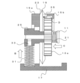
- FIG. FIG. FIG. FIG. FIG. FIG. FIG. Schematic diagram showing a positioning mechanism for a blade member 19.
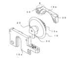
- FIG. FIG. 4 is an exploded perspective view of the blade member 19 and the positioning members 15a and 15b.
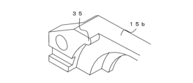
- An enlarged view of part E in FIG. 5A. 13 is a perspective view of the positioning member 15b when the blade member 19 and the positioning members 15a and 15b are assembled together.
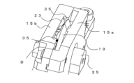
- FIG. 4 is a perspective view showing the positional relationship between the blade member 19 and a protrusion 35.
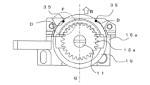
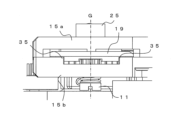
- FIG. 4 is a plan view showing the positional relationship between the blade member 19 and the protrusion 35.
- the operating part 29 of the cutting unit 9 protrudes from the main body part 3.
- the cutting unit 9 moves into the main body part 3.
- the cutting unit 9 is pressed by an elastic member in the direction in which it is pushed out of the main body part 3, so the cutting unit 9 is pushed into the main body part 3 against the pressing force of this elastic member.
- the blade tip of the cutting unit 9 moves further back than the optical fiber. In this state, the cutting unit 9 is held by a locking part (not shown).
- the cutting unit 9 moves. That is, the cutting unit 9 can move back and forth in the direction A in the figure. As the cutting unit 9 moves, the cutting edge comes into contact with the optical fiber, scratching it, and applying bending stress or the like to the scratched part, thereby cutting the optical fiber.
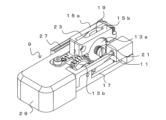
- Fig. 2A is an upper perspective view of the cutting unit 9
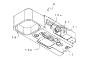
- Fig. 2B is a lower perspective view of the cutting unit 9
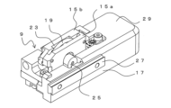
- Fig. 3A is a perspective view of the rear side of the cutting unit 9
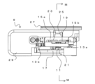
- Fig. 3B is a plan view of the cutting unit 9.
- the cutting unit 9 is composed of a base portion 17, a support portion 25 (Figs. 3A and 3B), a blade member 19, positioning members 15a and 15b, etc.
- a rail 27 is fixed to the side of the base portion 17.
- the rail 27 is slidable relative to a slide block (not shown) that is fixed to the main body portion 3 of the cutting device 1.
- the cutting unit 9 is movable relative to the main body portion 3 in the direction A in FIG. 1.
- a blade member 19 is disposed above the cutting unit 9.
- the blade member 19 is a roughly disk-shaped member, with its circumferential portion forming the cutting edge.
- the blade member 19 is housed inside the positioning members 15a, 15b.
- the positioning members 15a, 15b are members for regulating the position of the blade member 19, and are fixed to the base portion 17.
- a slit 23 is formed in the upper portion of the positioning members 15a, 15b.
- the tip of the blade member 19 protrudes from the slit 23 toward the surface side (upward) of the positioning members 15a, 15b.
- the positioning members 15a and 15b serve as positioning portions for regulating the position of the blade member 19. Details of how the blade member 19 is positioned by the positioning members 15a and 15b will be described later.
- a recess is formed on the bottom side of the operating part 29. This allows the user to insert their finger into the recess of the operating part 29 to operate the cutting unit 9.
- gear 13b protrudes from the bottom side of cutting unit 9.
- Gear 13b is an operating part for rotating blade member 19.
- Figure 4 is a schematic cross-sectional view taken along line M-M in Figure 3B.
- Gear 13a is fixed to blade member 19.
- Gear 13b meshes with gear 13a fixed to blade member 19. Therefore, by rotating gear 13b, it is possible to rotate blade member 19 together with gear 13a.
- the gear 13b can change the circumferential position of the blade member 19 protruding from the slit 23. This makes it possible to change the circumferential position of the blade member 19 at which it comes into contact with the optical fiber.
- the rotation of the gear 13b is restricted by a stopper (not shown), and the blade member 19 is fixed at a predetermined circumferential position.
- a support portion 25 is fixed to one side of the blade member 19.
- a pin 33 is connected to the underside of the support portion 25.
- the support portion 25 is disposed so that its height can be changed relative to the base portion 17, and is a portion that supports the blade member 19.
- the support portion 25 is pressed upward relative to the base portion 17 by the elastic member 31. Since the positioning members 15a, 15b are fixed to the base portion 17, the blade member 19 fixed to the support portion 25 is pressed upward relative to the positioning members 15a, 15b (in the direction of the slit 23, and the direction of the positioning portion) (arrow B in the figure).
- the height of the positioning members 15a, 15b relative to the base portion 17 may be adjustable.
- the height of the positioning members 15a, 15b relative to the base portion 17 can be finely adjusted by pushing down the positioning member 15a with a screw provided in a long hole of the positioning member 15a and pushing up the positioning member 15a with a set screw provided in a separately provided screw hole. This allows fine adjustment of the tip position of the blade member 19 relative to the base portion 17. Note that it is not essential to adjust the height of the positioning members 15a, 15b relative to the base portion 17, and the height of the positioning members 15a, 15b may be adjusted by other methods.
- a protrusion 35 is formed on the inner surface of the positioning member 15b as a positioning portion for the blade member 19, and the blade member 19 is positioned by contacting the protrusion 35.
- the positioning by the protrusion 35 of the positioning member 15b will be described in detail later.
- the blade member 19 is arranged so as to be sandwiched between the gear 13a and the support portion 25, and is fixed by the fixing screw 11. A part of the positioning member 15a is also sandwiched in the gap between the support portion 25 and the blade member 19. At this time, the elastic member 21, which is the second elastic member, is placed in the gap between the head of the fixing screw 11 and the gear 13a.
- the blade member 19 is pressed by the elastic member 21 in the axial direction of the blade member 19 (left-right direction in the figure) toward the support portion 25, so that one surface of the blade member 19 (the surface on the left side in the figure, which is approximately perpendicular to the axial direction excluding the tapered portion) is pressed by the elastic member 21 against the inner surface of the positioning member 15a (arrow C in the figure). This allows one surface of the blade member 19 to come into surface contact with the inner surface of the positioning member 15a fixed to the base portion 17.
- the axial position of the blade member 19 (position in the left-right direction in the figure) can be reliably positioned. Furthermore, because the blade member 19 and the positioning member 15a are in surface contact and pressed against each other, axial misalignment of the blade member 19 (the flat surface of the blade member 19 facing obliquely relative to the movement direction of the blade member 19 (direction perpendicular to the paper surface) or the height direction) can be suppressed, and the axial direction of the blade member 19 can be maintained perpendicular to both the movement direction and height direction of the blade member 19.
- Figure 5A is an exploded perspective view of the positioning members 15a, 15b, and the blade member 19. As described above, the inner surface of the positioning member 15a and one flat portion of the blade member 19 are in surface contact. Meanwhile, a pair of protrusions 35 are formed above the positioning member 15b on the side facing the positioning member 15a.
- Figure 5B is an enlarged view of part E in Figure 5A.
- Protrusion 35 protrudes from the upper inner surface side of positioning member 15b. Therefore, when positioning members 15a, 15b are connected and fixed, protrusion 35 is located near both ends of slit 23.
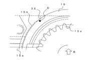
- Figure 6A shows the state in which the blade member 19 is housed inside the positioning members 15a, 15b, and is a perspective view of the positioning member 15b (positioning member 15b is shown in dotted lines).
- one of the opposing edges of the slit 23 (the edge of the inner surface of the positioning member 15b) has a pair of protrusions 35 that protrude toward the inner surface as a positioning portion for the blade member 19.
- the protrusions 35 are formed in two places on either side of the vertical center line (axis) of the blade member 19.
- the blade member 19 is generally disk-shaped, and the outer edge of the flat portion in the center has a tapered portion that gradually becomes thinner as it approaches the outer periphery. Therefore, when the blade member 19 is pressed upward (in the direction of arrow B in the figure), the tapered portion of the blade member 19 comes into contact with the protrusion 35 (part D in the figure).
- a part of the blade member 19 is inserted from the back side of the slit 23, and one of the tapered portions formed on both sides of the cutting edge of the blade member 19 comes into contact with each of the protrusions 35 on the inner edge of the slit 23. At this time, the tip of the blade member 19 protrudes toward the front side of the slit 23.
- Fig. 6B is an enlarged view of part F in Fig. 6A.
- Fig. 7A is an upper perspective view showing the contact portion between the protrusion 35 and the blade member 19, and Fig. 7B is a plan view of the blade member 19 as seen from above.
- the pair of protrusions 35 are positioned symmetrically with respect to the center line (the vertical center line passing through the axis, denoted by G in the figure) that extends in the height direction of the blade member 19.
- the blade member 19 is positioned at two points in the height direction when viewed from above. In this way, by positioning at two points at positions a specified distance away from the center line (axis), it is also possible to position the blade member 19 in the direction of movement (left and right direction in the figure).
- the height of the tip of the blade member 19 that protrudes toward the surface side of the slit 23 can be kept constant even if the rotation axis of the blade member 19 is eccentric. In other words, the positional relationship between the optical fiber and the blade portion of the blade member 19 can be maintained constant.
- the elastic member 21 allows the blade member 19 to come into surface contact with the inner surface of the positioning member 15a. This ensures that the axial orientation of the blade member 19 can be regulated reliably. In other words, the orientation of the blade portion of the blade member 19 relative to the optical fiber can be kept constant.
- the blade member 19 can always scratch the optical fiber under constant conditions. As a result, it is possible to suppress variations in the shape of the cut surface of the optical fiber and cutting defects caused by variations in the depth of the scratch. This makes it possible to improve the cutting quality of the optical fiber.
- the blade member 19 can be easily rotated by rotating the gear 13b. This makes it possible to change the circumferential position of the blade member 19 that comes into contact with the optical fiber. In this case, if the length from the center of rotation of the blade member 19 to the cutting edge is completely constant in the circumferential direction, the position of the cutting edge will not change even if the blade member 19 is rotated. On the other hand, if the rotation axis of the blade member 19 is slightly eccentric, the distance from the center of rotation of the blade member 19 to the cutting edge will change when the blade member 19 is rotated.
- the vicinity of the tip of the blade member 19 is positioned by point contact with a pair of protrusions 35 on the inner edge of the slit 23. Therefore, even if the axis of the blade member 19 is eccentric, the length of the cutting edge of the blade member 19 protruding from the slit 23 can be made approximately constant.
- the arrangement of the elastic members 21 and 31 and the structure of the support portion 25 are not limited to the example shown in the figure.
- the blade member 19 is pressed against the inner surface of the positioning member 15a by the elastic member 21 arranged on the axis of the blade member 19 to bring the blade member 19 into surface contact with the inner surface of the positioning member 15a.
- the blade member 19 may be fastened by another fixing member or the like to bring the blade member 19 and the inner surface of the positioning member 15a into surface contact with each other.
Landscapes
- Physics & Mathematics (AREA)
- Engineering & Computer Science (AREA)
- Mechanical Engineering (AREA)
- General Physics & Mathematics (AREA)
- Optics & Photonics (AREA)
- Life Sciences & Earth Sciences (AREA)
- Forests & Forestry (AREA)
- Light Guides In General And Applications Therefor (AREA)
- Nonmetal Cutting Devices (AREA)
Abstract
Description
3………本体部
5………蓋部
7………ホルダ載置部
9………切断ユニット
11………固定ネジ
13a、13b………歯車
15a、15b………位置決め部材
17………ベース部
19………刃部材
21………弾性部材
23………スリット
25………支持部
27………レール
29………操作部
31………弾性部材
33………ピン
35………突起
Claims (4)
- 光ファイバを切断する切断装置であって、
ベース部と、
円盤状の刃部材と、
前記ベース部に設けられ、前記刃部材の位置を規制する位置決め部材と、
前記ベース部に対して高さが変化可能に配置され、前記刃部材を支持する支持部と、
前記支持部を、前記ベース部に対して前記位置決め部材の位置決め部へ押圧する第1弾性部材と、
を具備し、
前記位置決め部材はスリットを有し、前記位置決め部として、前記スリットの対向する縁部の一方において内面側に突出する突起が形成され、前記突起は、上方から見て前記刃部材の軸を挟んで2か所に形成され、
前記位置決め部材の内部に前記刃部材が収容され、前記刃部材の一方の面が、前記位置決め部材の内面と面接触し、前記第1弾性部材によって前記刃部材が前記スリットの方向に押圧されて、前記刃部材の他方の面におけるテーパ部が、それぞれの前記突起と点接触して位置決めされ、前記刃部材の先端が、前記スリットの表面側に突出することを特徴とする切断装置。 - 一対の前記突起は、前記刃部材の軸を通る上下方向の中心線に対して対称な位置に配置されることを特徴とする請求項1記載の切断装置。
- 前記刃部材の軸方向から見た際に、前記突起の先端は円弧状に形成され、前記突起の円弧部が前記刃部材のテーパ部と点接触することを特徴とする請求項1記載の切断装置。
- 前記刃部材を、前記刃部材の軸方向であって、前記支持部の方向に押圧する第2弾性部材を具備し、前記第2弾性部材によって、前記刃部材の一方の面が、前記位置決め部材の内面に押圧されることを特徴とする請求項1記載の切断装置。
Priority Applications (4)
| Application Number | Priority Date | Filing Date | Title |
|---|---|---|---|
| CN202380084493.9A CN120380392A (zh) | 2022-12-27 | 2023-12-21 | 切断装置 |
| JP2024567712A JPWO2024143157A1 (ja) | 2022-12-27 | 2023-12-21 | |
| KR1020257018342A KR20250111320A (ko) | 2022-12-27 | 2023-12-21 | 절단 장치 |
| US19/220,920 US20250289071A1 (en) | 2022-12-27 | 2025-05-28 | Cutting device |
Applications Claiming Priority (2)
| Application Number | Priority Date | Filing Date | Title |
|---|---|---|---|
| JP2022209902 | 2022-12-27 | ||
| JP2022-209902 | 2022-12-27 |
Related Child Applications (1)
| Application Number | Title | Priority Date | Filing Date |
|---|---|---|---|
| US19/220,920 Continuation US20250289071A1 (en) | 2022-12-27 | 2025-05-28 | Cutting device |
Publications (1)
| Publication Number | Publication Date |
|---|---|
| WO2024143157A1 true WO2024143157A1 (ja) | 2024-07-04 |
Family
ID=91717607
Family Applications (1)
| Application Number | Title | Priority Date | Filing Date |
|---|---|---|---|
| PCT/JP2023/045958 Ceased WO2024143157A1 (ja) | 2022-12-27 | 2023-12-21 | 切断装置 |
Country Status (5)
| Country | Link |
|---|---|
| US (1) | US20250289071A1 (ja) |
| JP (1) | JPWO2024143157A1 (ja) |
| KR (1) | KR20250111320A (ja) |
| CN (1) | CN120380392A (ja) |
| WO (1) | WO2024143157A1 (ja) |
Citations (3)
| Publication number | Priority date | Publication date | Assignee | Title |
|---|---|---|---|---|
| JP2001356215A (ja) * | 2000-06-14 | 2001-12-26 | Sumiden Asahi Industries Ltd | 光ファイバカッタ |
| CN105445856A (zh) * | 2016-01-12 | 2016-03-30 | 南京吉隆光纤通信股份有限公司 | 光纤切割装置刀片固定组件 |
| JP2018163195A (ja) * | 2017-03-24 | 2018-10-18 | 古河電気工業株式会社 | 切断装置 |
-
2023
- 2023-12-21 KR KR1020257018342A patent/KR20250111320A/ko active Pending
- 2023-12-21 WO PCT/JP2023/045958 patent/WO2024143157A1/ja not_active Ceased
- 2023-12-21 JP JP2024567712A patent/JPWO2024143157A1/ja active Pending
- 2023-12-21 CN CN202380084493.9A patent/CN120380392A/zh active Pending
-
2025
- 2025-05-28 US US19/220,920 patent/US20250289071A1/en active Pending
Patent Citations (3)
| Publication number | Priority date | Publication date | Assignee | Title |
|---|---|---|---|---|
| JP2001356215A (ja) * | 2000-06-14 | 2001-12-26 | Sumiden Asahi Industries Ltd | 光ファイバカッタ |
| CN105445856A (zh) * | 2016-01-12 | 2016-03-30 | 南京吉隆光纤通信股份有限公司 | 光纤切割装置刀片固定组件 |
| JP2018163195A (ja) * | 2017-03-24 | 2018-10-18 | 古河電気工業株式会社 | 切断装置 |
Also Published As
| Publication number | Publication date |
|---|---|
| JPWO2024143157A1 (ja) | 2024-07-04 |
| CN120380392A (zh) | 2025-07-25 |
| KR20250111320A (ko) | 2025-07-22 |
| US20250289071A1 (en) | 2025-09-18 |
Similar Documents
| Publication | Publication Date | Title |
|---|---|---|
| US3436050A (en) | Adjustable mount for optical element | |
| CN101470241B (zh) | 镜片安装座 | |
| US20170235050A1 (en) | Optical fiber cutting apparatus | |
| JP2026506708A (ja) | 被覆除去装置 | |
| KR101928642B1 (ko) | 광섬유 절단 장치 | |
| US7669744B2 (en) | Device and method for cleaving optical fibers | |
| US20060281392A1 (en) | Lens edger | |
| WO2018163441A1 (ja) | 光ファイバ切断装置 | |
| JP6598812B2 (ja) | 切断装置 | |
| KR20250111320A (ko) | 절단 장치 | |
| WO2024143158A1 (ja) | 切断装置 | |
| WO2024143160A1 (ja) | 刃部材の取り付け方法、刃部材取付け用治具 | |
| CN113589463B (zh) | 光路可调整的新型镜头 | |
| JP2000225603A (ja) | 切断機の切断位置決め装置 | |
| JP2022188342A (ja) | 光学素子ホルダ | |
| CN113835181A (zh) | 一种多自由度调节的镜架 | |
| JP5310778B2 (ja) | レーザ走査光学装置 | |
| JP5321638B2 (ja) | レーザ走査光学装置 | |
| CN113126208A (zh) | 一种使用弹性刀片支架的光纤切割刀滑块 | |
| JP2001356215A (ja) | 光ファイバカッタ | |
| JP2019217679A (ja) | ホルダユニットおよびスクライブ装置 | |
| JPH0126403Y2 (ja) | ||
| JPH11153713A (ja) | 線状導光体の切断装置 | |
| JPH0141523Y2 (ja) | ||
| JPS59177988A (ja) | 半導体レ−ザの取付調節機構 |
Legal Events
| Date | Code | Title | Description |
|---|---|---|---|
| 121 | Ep: the epo has been informed by wipo that ep was designated in this application |
Ref document number: 23911937 Country of ref document: EP Kind code of ref document: A1 |
|
| WWE | Wipo information: entry into national phase |
Ref document number: 2024567712 Country of ref document: JP |
|
| WWE | Wipo information: entry into national phase |
Ref document number: 1020257018342 Country of ref document: KR |
|
| WWE | Wipo information: entry into national phase |
Ref document number: 202380084493.9 Country of ref document: CN |
|
| WWP | Wipo information: published in national office |
Ref document number: 1020257018342 Country of ref document: KR |
|
| WWP | Wipo information: published in national office |
Ref document number: 202380084493.9 Country of ref document: CN |
|
| NENP | Non-entry into the national phase |
Ref country code: DE |
|
| 122 | Ep: pct application non-entry in european phase |
Ref document number: 23911937 Country of ref document: EP Kind code of ref document: A1 |