WO2024142753A1 - ブラシ成形体および歯ブラシ - Google Patents
ブラシ成形体および歯ブラシ Download PDFInfo
- Publication number
- WO2024142753A1 WO2024142753A1 PCT/JP2023/042946 JP2023042946W WO2024142753A1 WO 2024142753 A1 WO2024142753 A1 WO 2024142753A1 JP 2023042946 W JP2023042946 W JP 2023042946W WO 2024142753 A1 WO2024142753 A1 WO 2024142753A1
- Authority
- WO
- WIPO (PCT)
- Prior art keywords
- fitting
- fitting hole
- tip
- brush
- dimension
- Prior art date
- Legal status (The legal status is an assumption and is not a legal conclusion. Google has not performed a legal analysis and makes no representation as to the accuracy of the status listed.)
- Ceased
Links
Images





Classifications
-
- B—PERFORMING OPERATIONS; TRANSPORTING
- B29—WORKING OF PLASTICS; WORKING OF SUBSTANCES IN A PLASTIC STATE IN GENERAL
- B29C—SHAPING OR JOINING OF PLASTICS; SHAPING OF MATERIAL IN A PLASTIC STATE, NOT OTHERWISE PROVIDED FOR; AFTER-TREATMENT OF THE SHAPED PRODUCTS, e.g. REPAIRING
- B29C65/00—Joining or sealing of preformed parts, e.g. welding of plastics materials; Apparatus therefor
- B29C65/56—Joining or sealing of preformed parts, e.g. welding of plastics materials; Apparatus therefor using mechanical means or mechanical connections, e.g. form-fits
- B29C65/565—Joining or sealing of preformed parts, e.g. welding of plastics materials; Apparatus therefor using mechanical means or mechanical connections, e.g. form-fits involving interference fits, e.g. force-fits or press-fits
-
- A—HUMAN NECESSITIES
- A46—BRUSHWARE
- A46B—BRUSHES
- A46B3/00—Brushes characterised by the way in which the bristles are fixed or joined in or on the brush body or carrier
- A46B3/005—Bristle carriers and bristles moulded as a unit
-
- A—HUMAN NECESSITIES
- A46—BRUSHWARE
- A46B—BRUSHES
- A46B5/00—Brush bodies; Handles integral with brushware
- A46B5/0095—Removable or interchangeable brush heads
-
- A—HUMAN NECESSITIES
- A46—BRUSHWARE
- A46D—MANUFACTURE OF BRUSHES
- A46D1/00—Bristles; Selection of materials for bristles
-
- B—PERFORMING OPERATIONS; TRANSPORTING
- B29—WORKING OF PLASTICS; WORKING OF SUBSTANCES IN A PLASTIC STATE IN GENERAL
- B29C—SHAPING OR JOINING OF PLASTICS; SHAPING OF MATERIAL IN A PLASTIC STATE, NOT OTHERWISE PROVIDED FOR; AFTER-TREATMENT OF THE SHAPED PRODUCTS, e.g. REPAIRING
- B29C33/00—Moulds or cores; Details thereof or accessories therefor
- B29C33/42—Moulds or cores; Details thereof or accessories therefor characterised by the shape of the moulding surface, e.g. ribs or grooves
-
- B—PERFORMING OPERATIONS; TRANSPORTING
- B29—WORKING OF PLASTICS; WORKING OF SUBSTANCES IN A PLASTIC STATE IN GENERAL
- B29C—SHAPING OR JOINING OF PLASTICS; SHAPING OF MATERIAL IN A PLASTIC STATE, NOT OTHERWISE PROVIDED FOR; AFTER-TREATMENT OF THE SHAPED PRODUCTS, e.g. REPAIRING
- B29C45/00—Injection moulding, i.e. forcing the required volume of moulding material through a nozzle into a closed mould; Apparatus therefor
- B29C45/17—Component parts, details or accessories; Auxiliary operations
- B29C45/26—Moulds
- B29C45/2626—Moulds provided with a multiplicity of narrow cavities connected to a common cavity, e.g. for brushes, combs
-
- A—HUMAN NECESSITIES
- A46—BRUSHWARE
- A46B—BRUSHES
- A46B2200/00—Brushes characterized by their functions, uses or applications
- A46B2200/10—For human or animal care
- A46B2200/1066—Toothbrush for cleaning the teeth or dentures
-
- B—PERFORMING OPERATIONS; TRANSPORTING
- B29—WORKING OF PLASTICS; WORKING OF SUBSTANCES IN A PLASTIC STATE IN GENERAL
- B29L—INDEXING SCHEME ASSOCIATED WITH SUBCLASS B29C, RELATING TO PARTICULAR ARTICLES
- B29L2031/00—Other particular articles
- B29L2031/42—Brushes
- B29L2031/425—Toothbrush
Definitions
- a brush molding comprising a head base portion formed of a soft resin and a plurality of filaments protruding from a support surface located on the front side of the head base portion in the thickness direction, wherein the head base portion has a fitting hole extending in a length direction perpendicular to the thickness direction and opening to one side in the length direction, and a fitting portion formed of a convex portion protruding into the fitting hole in a width direction perpendicular to the thickness direction and a concave portion recessed from the fitting hole in the width direction, the fitting portion being provided on both sides in the width direction, wherein the maximum dimension in the thickness direction of the head base portion is 3.0 mm or more and 4.5 mm or less, the soft resin has a Shore hardness of A90 or more and A100 or less, or a Shore hardness of D40 or more and D70 or less, and the ratio of the distance from the tip of the other side of the length direction to a position where the width dimension of the fitting hole
- [2] The brush molding described in [1], wherein the sum of the lengths of the fitting portions when viewed from the front is 10% or more and 30% or less of the total circumference of the fitting hole. [3] The brush molding according to [1] or [2], wherein the maximum dimension in the thickness direction of the fitting portion is 2.5 mm or less. [4] A brush molding described in any one of [1] to [3], wherein in the region where the fitting portion is located in the longitudinal direction, the thickness of the head base portion on the front side in the thickness direction relative to the fitting hole and the thickness of the head base portion on the back side opposite the front side in the thickness direction relative to the fitting hole are 0.5 mm or more and 1.5 mm or less, respectively.
- FIG. 2 is a front view of the brush molded body 20 and the toothbrush 1 according to the embodiment of the present invention.
- FIG. 2 is a side view of the brush molding 20 and the toothbrush 1.
- FIG. 2 is an enlarged front view of a fitting protrusion 12.
- FIG. 2 is an enlarged side view of a fitting protrusion 12.
- FIG. 2 is a front view of the brush molding 20. This is a cross-sectional view taken along line AA in FIG. 6.
- This is a cross-sectional view taken along the line CC in FIG. 2 is a cross-sectional view showing a simplified example of a mold MD for molding the brush molded body 20.
- FIG. FIG. 13 is an external perspective view of a core block SL2.
- the side where the handle body 10 is attached to the brush molding 20 is the rear end side (one side in the length direction), and the side opposite the rear end side is appropriately referred to as the tip side (the other side in the length direction).
- the direction perpendicular to the normal direction and the insertion direction is the width direction of the brush molding 20 (hereinafter simply referred to as the width direction).
- the long axis direction is the direction in which the filament 23 extends, which is parallel to the normal direction.
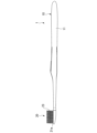
- FIG. 3 is a front view of the handle body 10.
- the handle body 10 includes a rod-shaped handle portion 11 and a fitting protrusion 12 that protrudes from the longitudinal tip side of the handle portion 11.
- the fitting protrusion 12 of the handle body 10 is inserted into a brush molding 20 (described later), whereby the brush molding 20 is attached by covering the fitting protrusion 12.
- the handle body 10 is formed from a hard resin.
- a hard resin is a resin with a flexural modulus (JIS K7171) of 1500 MPa or more and 3000 MPa or less.
- Specific examples include polypropylene resin (PP), polyacetal resin (POM), polybutylene terephthalate (PBT), polyester resin (PCTA), polyethylene terephthalate copolymer (PETG), and high density polyethylene (HDPE).
- PP which is a general-purpose resin, is preferable in terms of cost, and POM and PBT are even more preferable in order to ensure the strength of the mating protrusion 12.
- the shape of the handle portion 11 in a front view gradually narrows from the tip to the rear end, then extends at a constant width, then gradually widens and then narrows again in a curved manner.
- the shape of the handle portion 11 in a front view is approximately semicircular at the rear end.
- the shape of the handle portion 11 in side view extends from the tip side toward the rear end with a constant width, and then gradually widens until it reaches its maximum thickness, which is the finger rest area.
- the shape of the handle portion 11 in side view changes in a curved manner so that the width gradually narrows from the finger rest area of maximum thickness toward the rear end.
- the shape of the handle portion 11 in side view has a roughly semicircular rear end.
- the mating protrusion 12 is the portion that is covered by the brush molding 20 when the brush molding 20 is attached to the handle body 10.
- the rear end of the mating protrusion 12 is the rear end position of the brush molding 20 when the brush molding 20 is attached to the handle body 10.
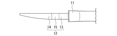
- Fig. 4 is an enlarged front view of the fitting protrusion 12.
- Fig. 5 is an enlarged side view of the fitting protrusion 12. 4 and 5, the fitting protrusion 12 has a base portion 13 provided on the tip side of the handle portion 11, a tip portion 14 provided at the tip of the base portion 13, and a recess 15. The tip portion 14 is located on the tip side of the recess 15.
- the depressions 15 are provided on both sides in the width direction.
- the two depressions 15 on both sides in the width direction are at the same position in the length direction.
- the depressions 15 have an arc shape with an arc center on the outside in the width direction and a concave shape on the inside.
- the depressions 15 are provided line-symmetrically with respect to the width direction.
- the base 13 and the tip 14 have a step in the thickness direction relative to the handle portion 11 on both the front side and the back side. That is, the dimension in the thickness direction of the base 13 and the tip 14 is smaller than the tip of the handle portion 11.
- the base 13 and the tip 14 have a step in the width direction relative to the handle portion 11. That is, the dimension in the width direction of the base 13 and the tip 14 is smaller than the tip of the handle portion 11.
- the base 13 has a constant widthwise dimension on the rear end side of the recess 15.
- the base 13, including the position where the recess 15 is formed, is formed to have a constant thickness that is thinner than the handle portion 11.
- the width dimension of the tip portion 14 gradually decreases toward the tip side.
- the width direction outline of the tip portion 14 is formed by a curve that curves into an arc shape.
- the thickness dimension of the tip portion 14 gradually decreases toward the tip side.
- the front surface of the tip portion 14 is flush with the front surface of the base portion 13.
- the back surface of the tip portion 14 curves toward the front side from the position flush with the back surface of the base portion 13 toward the tip side.
- the front and side shapes of the fitting protrusion 12 are substantially the same as those of a fitting hole 22 (described in detail later) in the brush molding 20 .
- Fig. 6 is a front view of the brush molding 20.
- Fig. 7 is a cross-sectional view taken along line AA in Fig. 6.
- Fig. 8 is a cross-sectional view taken along line BB in Fig. 6, and is a cross-sectional view at a first position.
- the brush molding 20 includes a head base 21 having a substantially rectangular shape when viewed from the front, and a plurality of filaments 23 provided on the front surface of the head base 21 .
- the filament 23 is generally columnar and protrudes from the support surface 21a of the head base 21 to the front side.
- the base end of the filament 23 is generally triangular prism with a generally triangular cross section, and the tip end is generally triangular pyramid extending from the generally triangular prism and tapering.
- the filaments 23 are arranged in a mixture of a staggered arrangement in which multiple rows are arranged along the width direction of the brush molding 20, such that adjacent rows in the insertion direction are shifted by half a pitch in the width direction, and a lattice arrangement in which adjacent rows in the insertion direction are arranged at the same pitch along the width direction.
- the cross-sectional shape of the filament 23 can be selected from a substantially triangular shape, a substantially polygonal shape such as a substantially square shape, a substantially circular shape, a substantially star shape, a substantially spatula shape, and the like.
- the filament 23 may be configured to extend in a straight line or have a tapered shape tapered from the base end.
- a triangular pyramid has one side parallel to the demolding direction (thickness direction) and a vertex spaced from directly above the center of the base end. Using this shape can reduce the amount of work required for cutting the mold, and production costs can be reduced.
- the head base portion 21 has a fitting hole 22 , a base 24 , a side wall 25 , a bottom wall 26 , a tip wall 27 , and a fitting portion 35 .
- the maximum dimension in the thickness direction of the head base 21 is preferably 3.0 mm or more and 4.5 mm or less.
- the lower limit is preferably 3.0 mm or more and more preferably 3.5 mm or more.
- the upper limit is preferably 4.5 mm or less and more preferably 4.0 mm or less.
- the fitting hole 22 extends in the insertion direction and opens at the end face 21b on the rear end side (one side in the length direction).
- Figure 9 is a cross-sectional view taken along C-C in Figure 8.
- the fitting hole 22 has a first portion 33 that opens at the end face 21b, and a second portion 34 that is located further towards the tip side than the first portion 33.
- the first portion 33 and the second portion 34 are positioned spaced apart from the support surface 21a and back surface 21c of the head base portion 21, respectively.
- the first portion 33 is located rearward of position K, which is the boundary between the second portion 34 and the mating portion 35 in the longitudinal direction.
- Position K is the position where the widthwise dimension from the tip of the mating hole 22 toward the rear end begins to decrease.
- the first portion 33 has a constant widthwise dimension rearward of the mating portion 35. As shown in FIG. 7, the first portion 33 has a constant thickness dimension.
- the second portion 34 is located closer to the tip than position K.
- the width dimension of the second portion 34 gradually decreases toward the tip.
- the contours of both sides of the width of the second portion 34 are formed by curves that are curved in an arc shape.
- the second portion 34 has a gradually smaller dimension in the thickness direction toward the tip side.
- the front surface of the second portion 34 is flush with the front surface of the first portion 33.
- the rear surface of the second portion 34 curves from the position flush with the rear surface of the first portion 33 toward the tip side toward the front side.
- the shape of the fitting hole 22 in a front view and a side view is substantially the same as that of the fitting protrusion 12 in the handle body 10 .
- the base 24 is located on the front side of the fitting hole 22.
- the base 24 has a support surface 21a from which the filament 23 protrudes.
- the support surface 21a is flat and perpendicular to the thickness direction.
- the side walls 25 are located on both sides of the fitting hole 22 in the width direction.
- the side walls 25 extend from both ends of the base 24 in the width direction toward the rear side.
- the side walls 25 are arranged at a constant interval in the width direction on the rear end side of position K. On the tip side of position K, the widthwise interval between the side walls 25 gradually decreases toward the tip side.
- the bottom wall 26 is located on the rear side of the fitting hole 22.
- the bottom wall 26 connects the rear ends of the side walls 25.
- the bottom wall 26 is disposed at a fixed distance in the thickness direction from the base 24 on the rear end side of position K. On the tip side of position K, the bottom wall 26 gradually extends in a direction toward the front side as it moves toward the tip side.
- the tip wall 27 is located on the tip side of the fitting hole 22.
- the tip wall 27 connects the tip of the base 24, the tip of the bottom wall 26, and the tip of the side wall 25.
- the fitting hole 22 is formed surrounded by the base 24, the side wall 25, the bottom wall 26, and the tip wall 27.
- the first curved portion 35a is located on the tip side and curves into an arc shape that contacts the fitting hole 22 formed on the inner surface of the side wall 25.
- the first curved portion 35a has an arc shape that convex outward in the width direction.
- the second portion 34 of the fitting hole 22 and the first curved portion 35a intersect at position K. If the maximum length of the fitting hole 22 is L1 and the distance from the front end to the rear end of the fitting hole 22 in the length direction is L2, the ratio of the distance L2 to the maximum length L1 is 50% or more. In other words, the position K is located at the center of the fitting hole 22 in the length direction or closer to the rear end than the center.
- the second curved portion 35b is located at the rear end and curves in an arc shape that contacts the fitting hole 22 formed on the inner surface of the side wall 25.
- the second curved portion 35b has an arc shape that convex outward in the width direction.
- the radius of the first curved portion 35a is larger than the radius of the second curved portion 35b.
- the angle of intersection of the tangents to the first curved portion 35a and the second curved portion 35b with respect to the longitudinal direction decreases as the distance from the center increases in the longitudinal direction. Since the radius of the first curved portion 35a is larger than the radius of the second curved portion 35b, the circumferential length of the first curved portion 35a is larger than the circumferential length of the second curved portion 35b. Therefore, the first curved portion 35a has a larger area where the tangent line intersects with the longitudinal direction at a small angle than the second curved portion 35b.
- the base 13 fits into the first portion 33, the tip 14 fits into the second portion 34, and the mating portion 35 fits into the recess 15.
- the handle body 10 and the head base 21 are integrated.
- polyurethane As the soft resin constituting the brush molded body 20, various elastomers can be used, but polyurethane is preferable. Since polyurethane tends to have a higher tensile strength than other elastomers such as styrene-based or polyester-based elastomers, by using polyurethane as a soft resin, mechanical strength can be ensured even if the material is thin, and damage can be reduced when the mating protrusion 12 in the handle body 10 is mated with the mating hole 22 and when the toothbrush 1 is in use.
- Polyurethane contains 0.01 to 1.0 wt% (mass%) of any of the following: saturated/unsaturated hydrocarbons with C10 or higher, higher alcohols, fatty acid amides, fatty acid esters, low molecular weight polyethylene, polyethylene glycol (PEG), fatty acid metal salts, long-chain fatty acids, fatty acid glycerin, liquid paraffin, and silicone, or a combination of these, and functions as a lubricant and release agent.
- FIG. 10 is a cross-sectional view showing a simplified example of a mold MD for molding the brush molded body 20.
- the mold MD includes a first mold MD1 and a second mold MD2 that move relatively in the opening/closing direction (the up-down direction in FIG. 10).
- the first mold MD1 and the second mold MD2 are clamped together with a parting surface PL, which is flush with the support surface 21a, as a joining surface.
- the first mold MD1 is attached to, for example, the fixed side of the injection molding machine, and is filled with molten resin from the injection molding machine.
- the second mold MD2 is attached to, for example, the movable side of the injection molding machine, and the mold MD is opened and closed by moving in the opening and closing direction (thickness direction of the brush molding body 20) relative to the first mold MD1.
- the first mold MD1 has a molding surface 21aM where the support surface 21a is molded and a cavity 23M where the filament 23 is molded when the first mold MD1 is clamped and joined to the second mold MD2.
- the second mold MD2 has a cavity 21M in which the head base portion 21 is molded when it is clamped and joined to the first mold MD1, a gate portion G that opens at the tip side of the cavity 21M and introduces molten resin into the cavity 21M, and an abutment surface 21eM that is provided at the end face 21b in the insertion direction and is perpendicular to the insertion direction.
- a side gate method is used as the gate portion G, but a pinpoint gate method or a tunnel gate method may also be used.
- the abutment surface 21eM extends in the second mold MD2 in a direction away from the PL surface from the position where the back surface of the head base portion 21 is molded.
- the second mold MD2 is provided with a slide core SL.
- the slide core SL has a body portion SL1 and a core block SL2.
- the core block SL2 is fixed to the parting surface PL side of the body portion SL1.
- the core block SL2 has a core portion 22M in which the fitting hole 22 is formed, and a molding surface 21bM perpendicular to the direction in which the core portion 22M protrudes and is inserted.
- the area of the body portion SL1 that faces the cavity 21M without abutting the abutment surface 21eM constitutes the molding surface 21bM. Before clamping, the molding surface 21bM is separated from the abutment surface 21eM.
- FIG. 11 is an external perspective view of the core block SL2.
- the core portion 22M has a first core portion 33M that forms the first portion 33, a second core portion 34M that forms the second portion 34, and a third core portion 35M formed by a recess that forms the fitting portion 35.
- the slide core SL moves in a direction in which the core portion 22M leaves the cavity 21M (the right side in FIG. 10; hereinafter, referred to as the leaving direction) so that the core portion 22M does not interfere with the release of the molded brush molding body 20.
- the moving direction of the slide core SL is preferably horizontal to avoid unexpected movement due to its own weight.
- the molten resin is introduced from the gate G into the cavity 21M, and fills the cavity 21M and also the cavity 23M.
- the molten resin filled into the cavity 21M and the cavity 23M is solidified by cooling for a predetermined time inside the mold MD, and the brush molding body 20 is formed.
- the second mold MD2 moves relative to the first mold MD1 to open the mold.
- the first mold MD1 and the second mold MD2 are separated from each other without the slide core SL moving.
- the filament 23 is released from the first mold MD1.
- the filament 23 is released from the first mold MD1, and further, the second mold MD2 moves relative to the first mold MD1, whereby the core portion 22M of the slide core SL moves in the direction of separation from the cavity 21M.
- the brush molding 20 from which the core portion 22M has been removed by forcible removal is released from the second mold MD2, and the gate on the tip side is cut off, producing a molded product with a gate mark on the tip.
- the soft resin constituting the brush molded body 20 has a lower hardness, which increases the flexibility of the brush molded body 20 and makes it easier to undergo reversible deformation, thereby reducing the load when the brush molded body 20 is forcibly removed.
- the soft resin constituting the brush molding 20 preferably has a Shore hardness of A90 or more and A100 or less, or a Shore hardness of D40 or more and D70 or less, and more preferably has a Shore hardness of A95 or more and A100 or less, or a Shore hardness of D50 or more and D66 or less.
- the Shore hardness of the soft resin is below the lower limit of the above range, there is a possibility that the brush molding 20 may come off during brushing from the handle body 10 with the fitting protrusion 12 inserted into the fitting hole 22. If the Shore hardness of the soft resin is above the upper limit of the above range, the flexibility is insufficient, and the load when forcibly removing the brush molding 20 becomes large. By setting the Shore hardness of the soft resin within the above range, it is possible to suppress detachment of the brush molding 20 during brushing use, while reducing the load when forcibly removing the brush molding 20.
- the ratio of the distance L2 from the tip to the position K where the widthwise dimension of the fitting hole 22 from the tip to the rear end in the longitudinal direction begins to decrease to the maximum longitudinal dimension L1 of the fitting hole 22 be 50% or more, the load during forced removal can be reduced.
- the tip side of the fitting hole 22 is closed by the tip wall 27, while the rear end side of the fitting hole 22 is open, and the shape is flexible. Therefore, if the ratio of the distance L2 to the maximum dimension L1 is less than 50%, the flexibility will be insufficient due to the proximity to the shielded tip side, and the load will be large when forcibly removed.
- the brush molding 20 becomes flexible and prone to reversible deformation, and the load during forced removal can be reduced.
- the tip wall 27 made only of soft resin is disposed on the tip side of the fitting protrusion 12, so that when used for brushing, the head base 21 is likely to bend in the thickness direction starting from the tip wall 27. Therefore, if position K is on the tip side, the fitting between the fitting portion 35 and the recess 15 will come loose and become detached.
- the position K which is the start position for forced removal, so that the ratio of the distance L2 to the maximum dimension L1 is 50% or more, preferably 60% or more, it is possible to prevent the brush molding 20 from detaching from the handle body 10 when used for brushing.
- the maximum dimension in the width direction of the head base portion 21 is 9.0 mm or more, and more preferably 13 mm or more.
- the sum of the lengths of the fitting portion 35 is preferably 10% or more and 30% or less of the total circumference of the fitting hole 22, and more preferably 15% or more and 25% or less. If the total length of the fitting portions 35 exceeds 30% of the total circumference of the fitting hole 22, the proportion of the fitting portions 35 increases, and the load increases when the brush body 20 is forcibly removed. If the total length of the fitting portions 35 falls below 10% of the total circumference of the fitting hole 22, the brush body 20 becomes more likely to come off when the brush body 20 is used for brushing.
- the sum of the lengths of the fitting portion 35 is preferably 70% or less of the maximum dimension L1 of the fitting hole 22, and more preferably 40% or more and 60% or less. If the total length of the fitting portions 35 exceeds 70% of the maximum dimension L1 of the fitting hole 22, the proportion of the fitting portions 35 increases, and the load increases when the brush body 20 is forcibly removed. If the total length of the fitting portions 35 falls below 40% of the maximum dimension L1 of the fitting hole 22, the brush body 20 becomes more likely to come off when the brush body 20 is used for brushing.
- the surface of the core portion 22M is generally not polished, friction tends to be high. Therefore, if the circumferential length of the fitting hole 22 or the maximum dimension L1 is too long, the load during forced removal due to friction between the brush molding 20 and the core portion 22M will be large, and if it is too short, there is a possibility that the trajectory of the core portion 22M may be distorted when moved in the removal direction, resulting in a large load during forced removal. Therefore, it is preferable to set the circumferential length of the fitting hole 22 and the maximum dimension L1 taking into consideration the load due to friction and the trajectory deviation of the core portion 22M.
- the maximum dimension in the thickness direction of the fitting portion 35 is preferably 2.5 mm or less, and more preferably 1.5 mm or more and 2.5 mm or less. If the maximum dimension in the thickness direction of the fitting portion 35 exceeds 2.5 mm, the load during forced removal will be large. If the maximum dimension in the thickness direction of the fitting portion 35 is less than 1.5 mm, there is a possibility that the brush molding 20 may come off during brushing. By setting the maximum dimension in the thickness direction of the fitting portion 35 to 1.5 mm or more and 2.5 mm or less, it is possible to suppress detachment of the brush molding 20 during brushing use, while reducing the load when forcibly removing it.
- the thickness of the base 24, which is the thickness of the head base portion on the front side in the thickness direction relative to the fitting hole 22, and the thickness of the bottom wall 26, which is the thickness of the head base portion 21 on the rear side relative to the fitting hole 22, are 0.5 mm or more and 1.5 mm or less, respectively. If the thickness exceeds 1.5 mm, the flexibility is insufficient, and the load when forcibly removing the brush body 20 becomes large. If the thickness is less than 0.5 mm, the brush body 20 may come off during brushing. By setting the above thicknesses to 0.5 mm or more and 1.5 mm or less, respectively, it is possible to suppress detachment of the brush molding 20 during brushing use, while reducing the load when forcibly removing the brush molding 20.
- the fitting hole 22 located on the tip side of the fitting portion 35 has a width dimension that gradually decreases toward the tip side.
- the widthwise dimension of the fitting hole 22 gradually decreases toward the tip side, so that the outlines of both sides in the widthwise direction of the fitting hole 22 have a shape having a draft slope that widens in the removal direction of the core portion 22M. Therefore, even if the fitting hole 22 located on the tip side of the fitting portion 35 is long, when the core portion 22M moves in the removal direction, the core portion 22M quickly separates from the head base portion 21 located on the tip side of the fitting portion 35 and having a draft slope, and the release resistance of the core portion 22M can be reduced.
- the difference between the maximum widthwise dimension of the fitting hole 22 located toward the tip side of the fitting portion 35 and the widthwise dimension at a position 1 mm away from the tip on one side in the longitudinal direction is preferably 2.0 mm or more, more preferably 2.5 mm or more, and even more preferably 3.0 mm or more. If the difference in the above dimensions is less than 2.0 mm, the load during forced removal will be large. By making the difference in the above dimensions 2.0 mm or more, the load during forced removal can be reduced.
- the fitting hole 22 located on the tip side of the fitting portion 35 has a thickness dimension that gradually decreases toward the tip side.
- the thickness dimension of the fitting hole 22 gradually becomes smaller toward the tip side, so that the contour of the back side of the fitting hole 22 in the thickness direction has a shape with a draft slope that widens in the removal direction of the core portion 22M. Therefore, even if the engagement hole 22 located further towards the tip side than the engagement portion 35 is longer, when the core portion 22M moves in the removal direction, the core portion 22M quickly separates from the head base portion 21 which has a draft slope located further towards the tip side than the engagement portion 35, thereby reducing the release resistance of the core portion 22M.
- the difference between the maximum thickness dimension of the fitting hole 22 located toward the tip side of the fitting portion 35 and the thickness dimension at a position 1 mm away from the tip on one side in the longitudinal direction is preferably 0.5 mm or more, more preferably 0.75 mm or more, and even more preferably 1.0 mm or more. If the difference in the above dimensions is less than 0.5 mm, the load during forced removal will be large. As described above, when used for brushing, the head base portion 21 tends to bend in the thickness direction starting from the tip wall 27, and the engagement between the engagement portion 35 and the recess 15 tends to come loose and become detached.
- the starting point of bending is set on the tip side, and the tip side of the fitting hole 22 is made thinner, thereby preventing the brush molding 20 from detaching from the handle body 10 when used for brushing.
- the fitting hole 22 has at least an area with a thickness of 1.5 mm or less, or the head base portion 21 has at least an area with a thickness of 3.5 mm or less.
- the radius of the first curved portion 35a is larger than the radius of the second curved portion 35b, so the first curved portion 35a has a larger area where the tangent crosses the length direction at a smaller angle than the second curved portion 35b.
- the length direction is the direction in which the core portion 22M is removed, a normal force is generated in the first curved portion 35a due to the force applied from the core portion 22M to the first curved portion 35a during forced removal, which serves as resistance during forced removal.
- the component of the normal force in the length direction (removal direction) is maximum when the cross angle of the tangent of the curved fitting portion 35 with respect to the length direction is 90°, and decreases as the cross angle decreases.
- the resistance of the fitting portion 35 caused by the normal force is small, and the load during forced removal can be reduced.
- the cross-sectional area of the head base portion 21 including the fitting hole 22 at a first position in the longitudinal direction where the width dimension of the fitting hole 22 is smallest is defined as A1.
- the cross-sectional area of the fitting hole 22 at the first position is defined as A2.
- the first position is the longitudinal position of the center of the arc of the fitting portion 35 having a convex arc shape.
- the cross-sectional area of the head base portion 21 including the fitting hole 22 at a second position in the longitudinal direction where the width dimension of the fitting hole 22 is maximum is defined as B1.
- the cross-sectional area of the fitting hole 22 at the second position is defined as B2.
- the second position is position K.
- the cross-sectional area of the head base portion 21 including the fitting hole 22 at a third position in the longitudinal direction where the width dimension of the fitting hole 22 is smallest is defined as C1.
- the cross-sectional area of the fitting hole 22 at the third position is defined as C2.
- the third position is a position in the longitudinal direction 1 mm away from the tip of the fitting hole 22 toward the rear end.
- the value expressed by B1/B2-A1/A2 is 0.15 or less, and the value expressed by B1/B2-C1/C2 is 0.10 or more. If the value expressed by B1/B2-A1/A2 exceeds 0.15, this means that the fitting portion 35 protrudes too far into the fitting hole 22, and the load during forced removal becomes large. If the value expressed by B1/B2-C1/C2 is below 0.10, this means that the amount of change in the fitting hole 22 from the second position to the first position is small, and the load during forced removal becomes large. Therefore, by setting the value expressed by B1/B2-A1/A2 to 0.15 or less and the value expressed by B1/B2-C1/C2 to 0.10 or more, the load during forced removal can be reduced.
- the above-mentioned measurement of the fitting hole 22 of the brush molding 20 is performed by exposing the desired shape from the front or rear side using a cutting tool such as a cutter or nippers while the handle body 10 is fitted. Measurements may also be performed using an X-ray CT scanner or the like. In addition, since the front view and side view shapes of the fitting hole 22 are substantially the same as the fitting protrusion 12 in the handle body 10, the shape of the fitting protrusion 12 may be measured instead.
- the brush molding 20 and toothbrush 1 of this embodiment even if the Shore hardness is 90A or more, the load when forcibly removed can be reduced, so that molding defects such as curling can be prevented, and the brush molding 20 can be prevented from coming off when used for brushing, thereby maintaining the fitting strength.
- the fitting protrusion of the handle body was inserted into the sample of the brush molded body to prepare a sample toothbrush.
- the sample handle body was made of polyacetal resin (POM).
- POM polyacetal resin
- the brush molding sample had a maximum thickness dimension of 4.0 mm and a maximum width dimension of 12.0 mm.
- the width of the fitting hole and the fitting protrusion was 8.0 mm.
- the dimension of the fitting hole and the fitting protrusion in the fitting portion in the thickness direction was set to 2.0 mm.
- the maximum dimension in the thickness direction of the base and the bottom wall was 1.0 mm.
- the filaments had a triangular pyramid cross section and a hair length of 10.0 mm, and were arranged in a lattice pattern with 10 filaments in the width direction and 17 filaments in the length direction when viewed from the front.
- the fitting portion 35 is formed as a protrusion that protrudes in the width direction into the fitting hole 22, but is not limited to this configuration.
- the fitting portion 35 may be configured as a recess recessed outward in the width direction from the fitting hole 22 .
- the fitting protrusion 12 of the handle body 10 may be provided with convex portions on both sides in the width direction, which fit into the concave portions that serve as the fitting portions when inserted into the fitting holes 22 .
- the fitting portion 35 is provided at a position where the ratio of the distance L2 to the maximum dimension L1 is less than 50%, the flexibility in that region is insufficient, but the load caused by forcible removal is small because the distance in the major axis direction where the load is applied during forcible removal is short.
- the fitting portion 35 is provided only at a position where the ratio of the distance L2 is less than 50%, as described above, the head base portion 21 is likely to bend in the thickness direction starting from the tip wall 27 during brushing use, and the fitting portion 35 and the recess 15 are likely to come out of engagement and become detached. Therefore, at least one fitting portion 35 must fill 50% or more, but it may be located at a position less than 50%.
- the dimension in the width direction of the fitting hole 22 located on the tip side of the fitting portion 35 is gradually decreased toward the tip side. In that case, the undercut portion becomes smaller, and the load during forced removal can be further reduced. It is also preferable that the dimension in the thickness direction of the fitting hole 22 located on the tip side of the fitting portion 35 is gradually decreased toward the tip side. Even in that case, the advantage of the undercut portion becoming smaller as described above is obtained. Regarding detachment, there is no disadvantage in using the fitting portion 35 at a position less than 50%.
- the configuration in which one fitting portion 35 is provided in the length direction on each side in the width direction has been exemplified, but the present invention is not limited to this configuration.
- the fitting portion 35 may be configured to be provided in a plurality in the length direction on both sides in the width direction.
- the handle body 10 is formed from a hard resin, but this is not limited to this configuration.
- a part of the handle body 10 (handle portion 11, etc.) may be coated with a soft resin. If this configuration is adopted, the decorativeness and gripping properties can be improved.
Landscapes
- Engineering & Computer Science (AREA)
- Mechanical Engineering (AREA)
- Manufacturing & Machinery (AREA)
- Brushes (AREA)
Priority Applications (2)
| Application Number | Priority Date | Filing Date | Title |
|---|---|---|---|
| KR1020257008310A KR20250126700A (ko) | 2022-12-27 | 2023-11-30 | 브러시 성형체 및 칫솔 |
| JP2024567340A JPWO2024142753A1 (https=) | 2022-12-27 | 2023-11-30 |
Applications Claiming Priority (2)
| Application Number | Priority Date | Filing Date | Title |
|---|---|---|---|
| JP2022-209664 | 2022-12-27 | ||
| JP2022209664 | 2022-12-27 |
Publications (1)
| Publication Number | Publication Date |
|---|---|
| WO2024142753A1 true WO2024142753A1 (ja) | 2024-07-04 |
Family
ID=91717215
Family Applications (1)
| Application Number | Title | Priority Date | Filing Date |
|---|---|---|---|
| PCT/JP2023/042946 Ceased WO2024142753A1 (ja) | 2022-12-27 | 2023-11-30 | ブラシ成形体および歯ブラシ |
Country Status (3)
| Country | Link |
|---|---|
| JP (1) | JPWO2024142753A1 (https=) |
| KR (1) | KR20250126700A (https=) |
| WO (1) | WO2024142753A1 (https=) |
Citations (4)
| Publication number | Priority date | Publication date | Assignee | Title |
|---|---|---|---|---|
| JP2003339443A (ja) * | 2002-05-30 | 2003-12-02 | Masanobu Nakamura | ブラシ部が交換可能な歯ブラシの嵌合構造 |
| JP2010051795A (ja) * | 2008-08-01 | 2010-03-11 | Earth Chem Corp Ltd | 歯茎マッサージ用ブラシ |
| JP2015211750A (ja) * | 2014-05-02 | 2015-11-26 | Nsファーファ・ジャパン株式会社 | 歯茎マッサージ用ブラシ |
| WO2021131526A1 (ja) * | 2019-12-23 | 2021-07-01 | ライオン株式会社 | 歯ブラシ |
Family Cites Families (1)
| Publication number | Priority date | Publication date | Assignee | Title |
|---|---|---|---|---|
| JP7190864B2 (ja) | 2018-10-17 | 2022-12-16 | ライオン株式会社 | 歯ぐきケア用具 |
-
2023
- 2023-11-30 WO PCT/JP2023/042946 patent/WO2024142753A1/ja not_active Ceased
- 2023-11-30 KR KR1020257008310A patent/KR20250126700A/ko active Pending
- 2023-11-30 JP JP2024567340A patent/JPWO2024142753A1/ja active Pending
Patent Citations (4)
| Publication number | Priority date | Publication date | Assignee | Title |
|---|---|---|---|---|
| JP2003339443A (ja) * | 2002-05-30 | 2003-12-02 | Masanobu Nakamura | ブラシ部が交換可能な歯ブラシの嵌合構造 |
| JP2010051795A (ja) * | 2008-08-01 | 2010-03-11 | Earth Chem Corp Ltd | 歯茎マッサージ用ブラシ |
| JP2015211750A (ja) * | 2014-05-02 | 2015-11-26 | Nsファーファ・ジャパン株式会社 | 歯茎マッサージ用ブラシ |
| WO2021131526A1 (ja) * | 2019-12-23 | 2021-07-01 | ライオン株式会社 | 歯ブラシ |
Also Published As
| Publication number | Publication date |
|---|---|
| KR20250126700A (ko) | 2025-08-25 |
| JPWO2024142753A1 (https=) | 2024-07-04 |
Similar Documents
| Publication | Publication Date | Title |
|---|---|---|
| JP7607587B2 (ja) | 歯ブラシ | |
| KR102085517B1 (ko) | 칫솔 | |
| JPWO2016199834A1 (ja) | 歯間清掃具 | |
| WO2010082294A1 (ja) | スライドファスナー | |
| WO2024142753A1 (ja) | ブラシ成形体および歯ブラシ | |
| US12383385B2 (en) | Interdental cleaning tool | |
| KR20170137713A (ko) | 치간 브러시 | |
| JP7617835B2 (ja) | ブラシ成形体および歯ブラシ | |
| US12495888B2 (en) | Interdental cleaning tool | |
| WO2020138264A1 (ja) | 歯間ブラシ | |
| TWI906438B (zh) | 刷毛成形體以及牙刷 | |
| WO2024142677A1 (ja) | 歯ブラシ | |
| JP2017000777A (ja) | 歯間清掃具 | |
| KR20250121527A (ko) | 칫솔 | |
| JP7638227B2 (ja) | 歯ブラシ | |
| CN223008635U (zh) | 牙刷 | |
| JP7575886B2 (ja) | 歯間清掃具 | |
| JP7499649B2 (ja) | カバー | |
| WO2025070016A1 (ja) | 歯ブラシ | |
| JP2024052102A (ja) | 歯ブラシ | |
| JPH0763989B2 (ja) | 樹脂成形金型 | |
| WO2019107417A1 (ja) | 歯間清掃具の製造方法 |
Legal Events
| Date | Code | Title | Description |
|---|---|---|---|
| 121 | Ep: the epo has been informed by wipo that ep was designated in this application |
Ref document number: 23911534 Country of ref document: EP Kind code of ref document: A1 |
|
| WWE | Wipo information: entry into national phase |
Ref document number: 2024567340 Country of ref document: JP |
|
| WWE | Wipo information: entry into national phase |
Ref document number: CN2023900006763 Country of ref document: CN |
|
| NENP | Non-entry into the national phase |
Ref country code: DE |
|
| WWP | Wipo information: published in national office |
Ref document number: 1020257008310 Country of ref document: KR |
|
| 122 | Ep: pct application non-entry in european phase |
Ref document number: 23911534 Country of ref document: EP Kind code of ref document: A1 |