WO2024142537A1 - 自動分析装置 - Google Patents
自動分析装置 Download PDFInfo
- Publication number
- WO2024142537A1 WO2024142537A1 PCT/JP2023/036661 JP2023036661W WO2024142537A1 WO 2024142537 A1 WO2024142537 A1 WO 2024142537A1 JP 2023036661 W JP2023036661 W JP 2023036661W WO 2024142537 A1 WO2024142537 A1 WO 2024142537A1
- Authority
- WO
- WIPO (PCT)
- Prior art keywords
- analysis
- container
- analysis unit
- zone
- area
- Prior art date
- Legal status (The legal status is an assumption and is not a legal conclusion. Google has not performed a legal analysis and makes no representation as to the accuracy of the status listed.)
- Ceased
Links
Images




Classifications
-
- G—PHYSICS
- G01—MEASURING; TESTING
- G01N—INVESTIGATING OR ANALYSING MATERIALS BY DETERMINING THEIR CHEMICAL OR PHYSICAL PROPERTIES
- G01N35/00—Automatic analysis not limited to methods or materials provided for in any single one of groups G01N1/00 - G01N33/00; Handling materials therefor
- G01N35/10—Devices for transferring samples or any liquids to, in, or from, the analysis apparatus, e.g. suction devices, injection devices
- G01N35/1002—Reagent dispensers
-
- G—PHYSICS
- G01—MEASURING; TESTING
- G01N—INVESTIGATING OR ANALYSING MATERIALS BY DETERMINING THEIR CHEMICAL OR PHYSICAL PROPERTIES
- G01N35/00—Automatic analysis not limited to methods or materials provided for in any single one of groups G01N1/00 - G01N33/00; Handling materials therefor
- G01N35/10—Devices for transferring samples or any liquids to, in, or from, the analysis apparatus, e.g. suction devices, injection devices
- G01N35/1004—Cleaning sample transfer devices
-
- G—PHYSICS
- G01—MEASURING; TESTING
- G01N—INVESTIGATING OR ANALYSING MATERIALS BY DETERMINING THEIR CHEMICAL OR PHYSICAL PROPERTIES
- G01N35/00—Automatic analysis not limited to methods or materials provided for in any single one of groups G01N1/00 - G01N33/00; Handling materials therefor
- G01N2035/00178—Special arrangements of analysers
- G01N2035/00277—Special precautions to avoid contamination (e.g. enclosures, glove- boxes, sealed sample carriers, disposal of contaminated material)
-
- G—PHYSICS
- G01—MEASURING; TESTING
- G01N—INVESTIGATING OR ANALYSING MATERIALS BY DETERMINING THEIR CHEMICAL OR PHYSICAL PROPERTIES
- G01N35/00—Automatic analysis not limited to methods or materials provided for in any single one of groups G01N1/00 - G01N33/00; Handling materials therefor
- G01N2035/00178—Special arrangements of analysers
- G01N2035/00306—Housings, cabinets, control panels (details)
-
- G—PHYSICS
- G01—MEASURING; TESTING
- G01N—INVESTIGATING OR ANALYSING MATERIALS BY DETERMINING THEIR CHEMICAL OR PHYSICAL PROPERTIES
- G01N35/00—Automatic analysis not limited to methods or materials provided for in any single one of groups G01N1/00 - G01N33/00; Handling materials therefor
- G01N35/00584—Control arrangements for automatic analysers
- G01N35/00722—Communications; Identification
- G01N35/00732—Identification of carriers, materials or components in automatic analysers
- G01N2035/00792—Type of components bearing the codes, other than sample carriers
- G01N2035/00811—Type of components bearing the codes, other than sample carriers consumable or exchangeable components other than sample carriers, e.g. detectors, flow cells
-
- G—PHYSICS
- G01—MEASURING; TESTING
- G01N—INVESTIGATING OR ANALYSING MATERIALS BY DETERMINING THEIR CHEMICAL OR PHYSICAL PROPERTIES
- G01N35/00—Automatic analysis not limited to methods or materials provided for in any single one of groups G01N1/00 - G01N33/00; Handling materials therefor
- G01N35/00584—Control arrangements for automatic analysers
- G01N35/00722—Communications; Identification
- G01N2035/00891—Displaying information to the operator
- G01N2035/0091—GUI [graphical user interfaces]
-
- G—PHYSICS
- G01—MEASURING; TESTING
- G01N—INVESTIGATING OR ANALYSING MATERIALS BY DETERMINING THEIR CHEMICAL OR PHYSICAL PROPERTIES
- G01N35/00—Automatic analysis not limited to methods or materials provided for in any single one of groups G01N1/00 - G01N33/00; Handling materials therefor
- G01N35/02—Automatic analysis not limited to methods or materials provided for in any single one of groups G01N1/00 - G01N33/00; Handling materials therefor using a plurality of sample containers moved by a conveyor system past one or more treatment or analysis stations
- G01N35/04—Details of the conveyor system
- G01N2035/0401—Sample carriers, cuvettes or reaction vessels
- G01N2035/0437—Cleaning cuvettes or reaction vessels
Definitions
- the present invention relates to an automatic analyzer.
- Automatic analyzers such as biochemical analyzers and immunological analyzers, are known as devices for analyzing samples such as blood and urine collected from patients.
- a technology has been disclosed for reading RFID tags attached to containers that hold solutions such as reagents (see Patent Document 1).
- Patent Document 1 it is necessary to devise the layout of the flow paths and reagent installation positions connected to various mechanisms in order to ensure reliability and prevent accidents such as leakage of detergents used in the analysis, such as alkaline detergents and acidic detergents used in mechanisms related to biochemical analysis items, cleaning solutions and replacement solutions used in mechanisms related to immunological analysis items, and reference electrode standard solutions and dilution solutions used in the measurement of electrolyte items, and to avoid confusing the user when changing reagents.
- detergents used in the analysis such as alkaline detergents and acidic detergents used in mechanisms related to biochemical analysis items, cleaning solutions and replacement solutions used in mechanisms related to immunological analysis items, and reference electrode standard solutions and dilution solutions used in the measurement of electrolyte items, and to avoid confusing the user when changing reagents.
- the object of the present invention is to provide an automated analyzer that is easy to maintain and highly reliable.
- the present invention includes multiple means for solving the above problems, and an example thereof includes a first analysis unit that analyzes a first group of analysis items, a second analysis unit that analyzes a second group of analysis items different from the first group of analysis items, and a housing that houses the first analysis unit and the second analysis unit.
- a first area including the first analysis unit and the second analysis unit and a second area arranged vertically below the first area are set, the second area is divided into a first zone that stores a first container that stores a first liquid used in the analysis by the first analysis unit and a second zone that stores a second container that stores a second liquid used in the analysis by the second analysis unit, and the first container and the second container are arranged on a plate surface that constitutes the bottom surface of the housing.
- the present invention provides an automated analyzer that is easy to maintain and highly reliable while maintaining the operability of conventional products. Problems, configurations, and effects other than those described above will become clear from the explanation of the following examples.
- FIG. 1 is a diagram showing an overview of an automatic analyzer according to an embodiment of the present invention.
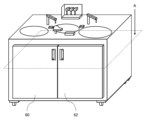
- FIG. 2 is a diagram showing an outline of a door in the automatic analyzer of the embodiment.
- FIG. 2 is a diagram showing the automatic analyzer of the embodiment with the left door open.
- FIG. 2 is a diagram showing the automatic analyzer of the embodiment with the right door open.
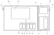
- 3 is a cross-sectional view of the device below plane A in FIG. 2 .
- 4 is a flowchart illustrating the flow of a reagent container replacement operation in the automatic analyzer of the embodiment.
- a biochemical analysis item group is exemplified as the first analysis item group
- an immunological analysis item group is exemplified as the second analysis item group different from the first analysis item group
- the first analysis item group and the second analysis item group are not limited to these items and can be selected as appropriate.
- Figure 1 is a diagram showing an overview of the automatic analyzer.
- an automatic analyzer also called a multi-purpose automatic analyzer
- the diagram shows the arrangement of containers for reagents (hereinafter referred to as system reagents) that are used in common for multiple analysis items out of the liquids used in the analysis, and units related to the system reagents.
- system reagents containers for reagents
- the automated analyzer 1 is a device for analyzing samples using reagents corresponding to predetermined analysis items, and includes a sample disk 25, a sample dispensing mechanism 50, a reagent disk 40, a reagent dispensing mechanism 42, a reaction tank 52, an immunoassay section 30, an ISE measurement section 58, a container washing mechanism 56 for washing reaction containers for biochemical analysis, a reader 18 for reading RFID, a control device 10, etc.
- the specimen disk 25 has a ring-shaped structure capable of holding multiple specimen containers (not shown) that contain the specimens to be analyzed in the first and second analysis items, and has an access position (specimen aspiration position) for the specimen dispensing mechanism 50.
- the specimen disk 25 rotates just before the specimen dispensing mechanism 50 aspirates the specimen to be analyzed, thereby transporting the specimen container to the specimen aspiration position.
- the reaction chamber 52 has a ring-shaped arrangement of positions for holding reaction vessels used in biochemical analysis and ISE analysis, and disposable reaction vessels used in immunoanalysis.
- reaction vessel refers to both reaction vessels used in biochemical analysis and ISE analysis, and disposable reaction vessels used in immunoanalysis.
- the reaction chamber 52 is temperature-controlled to promote the reaction between the sample and reagent, and has a rotation drive mechanism that moves the reaction vessels on the reaction chamber 52 to a designated position.
- the reagent disk 40 has a structure capable of holding multiple reagent containers (not shown) in a ring shape, which contain reagents to be reacted with a sample to produce a reaction liquid, and has an access position (reagent suction position) for the reagent dispensing mechanism 42.
- the reagent disk 40 rotates just before the reagent dispensing mechanism 42 aspirates the reagent, thereby transporting the reagent container to the reagent suction position.
- the reagent disk 40 also has a cooling mechanism for keeping the reagent containers cool.
- the reagent disk 40 may also be configured to be capable of arranging multiple reagent containers in a double ring shape.
- the reagent containers may each be made up of a number of different reagent bottles. If the reagent containers have different shapes, a dedicated position may be provided to hold each reagent container, or the shape may be such that both reagent containers can be held in one position.
- the reagent dispensing mechanism 42 is composed of a rotation drive mechanism, a vertical drive mechanism, and a reagent probe so that it can access a reaction vessel placed at a reagent discharge position where it dispenses a reagent on the reaction vessel 52.
- the rotation drive mechanism and the vertical drive mechanism move between a reagent suction position and a reagent discharge position, and the reagent is aspirated at the reagent suction position and discharged into a reaction vessel on the reaction vessel 52.
- the reagent moves to the reagent probe washing vessel 44, where it is held in a washing liquid container 131 and washed with washing liquid whose supply is controlled by opening and closing the solenoid valve 141 via flow paths 137 and 138, and then the next reagent dispensing operation begins.
- sample dispensing mechanism 50 and the reagent dispensing mechanism 42 are not limited to a configuration in which each position is accessed by a rotational movement, but may be configured to access each position by a linear movement.
- the reaction is promoted in the temperature-controlled reaction tank 52.
- the reaction tank 52 rotates, and the transmitted light of the reaction vessel containing the reaction solution of the biochemical item is measured by a photometer (not shown) provided near the reaction tank 52. The measurement results are sent to the control device 10.
- the reaction vessel into which the sample for ISE analysis has been dispensed is moved to the sample suction position of the ISE measurement unit 58.
- the sample is sucked into the flow path that passes through the inside of the ISE electrode by the syringe 59 of the ISE measurement unit 58.
- the potential difference is then measured with the reference electrode that has sucked in the standard solution held in the standard solution container 151, the supply of which is controlled by opening and closing the solenoid valve 154 provided on the flow path 157.
- the potential difference information is sent to the control device 10.
- the flow path in the ISE measurement unit 58 that was used for the analysis is washed with the standard solution or pure water, and is used for the next analysis.
- the disposable reaction vessel on the reaction tank 52 containing the reaction liquid for the immunoassay item is moved to the reaction vessel transport position and transported to the immunoassay section 30 by a reaction vessel transport mechanism (not shown).
- the disposable reaction vessel transported to the immunoassay section 30 is subjected to B/F separation to separate unreacted components from reacted components in the liquid in which the sample and reagent have reacted, and then the reaction liquid suction nozzle suctions the reaction liquid and sends it to the immunoassay cell (also called a flow cell), the signal is measured, and the measurement results are sent to the control device 10.
- the immunoassay section 30 is equipped with a buffer solution nozzle 32, a cleaning solution nozzle 34, a replacement solution nozzle 36, a B/F separation unit, a reaction solution suction nozzle, and an immunoassay cell.
- the buffer solution in the buffer solution container 130 is supplied to the buffer solution nozzle 32 via a flow path 136 by the suction and discharge operations of a syringe 133.
- An electromagnetic valve 140 is disposed on the flow path 136.
- the buffer solution is discharged into a reaction container disposed in the B/F separation unit.
- the cleaning liquid nozzle 34 is supplied with cleaning liquid from the cleaning liquid container 131 via the flow path 137 by the discharge action of the pump 134.
- the cleaning liquid discharged from the cleaning liquid nozzle 34 is supplied from the reaction liquid suction nozzle to the inside of the immune cell after the reaction liquid measurement has been completed, for cleaning.
- the cleaning liquid from the cleaning liquid container 131 is supplied to the reagent probe washing tank 44 via a flow path 138 branched from the flow path 137 by the discharge action of the pump 134.
- An electromagnetic valve 142 is arranged on the part of the flow path 137 closer to the cleaning liquid nozzle 34 than the branch point with the flow path 138, and an electromagnetic valve 141 is arranged on the flow path 138.
- the replacement liquid nozzle 36 is supplied with the replacement liquid in the replacement liquid container 132 via the flow path 139 by the discharge operation of the pump 135.
- the replacement liquid discharged from the replacement liquid nozzle 36 is sucked into the reaction liquid suction nozzle and supplied into the immune cell before measurement in the immune cell and after cleaning with the cleaning liquid.
- An electromagnetic valve 143 is disposed on the flow path 139.
- reaction vessels on the reaction tank 52 used for biochemical analysis and ISE analysis have residues discharged from the reaction vessel by the vessel cleaning mechanism 56.
- the vessels are then held in the detergent vessel 150, and washed with detergent whose supply is controlled by opening and closing the solenoid valve 153 via the flow path 156 branching off from the flow path 155, and then used for the next analysis.
- the system reagents used in the biochemical analysis items are detergent, and the system reagents used in the immunological analysis items are buffer solution, cleaning solution, and replacement solution.
- a standard solution container 151 is placed, which contains a standard solution of the system reagent for ISE analysis.
- the reader 18 reads information from tags that store information about reagents attached to reagent containers, and from tags that store information about the automatic analyzer 1 attached to objects such as consumables used in the automatic analyzer 1 or parts of the device configuration.
- the housing 20 houses a biochemical analysis section including a reaction chamber 52, a container cleaning mechanism 56, and a photometer, an ISE measurement section 58, and an immunoassay section 30.
- the automated analyzer 1 is equipped with a control device 10 that controls the operation of each device within the automated analyzer 1, including the sample disk 25 and the sample dispensing mechanism 50.
- the control device 10 may be configured from a computer having input devices such as a display 14, a keyboard 15, and a mouse 16, a storage unit 13, a control unit 12 configured from a CPU, and memory, or may be configured from a single computer or multiple computers, and is not particularly limited.
- the display 14 displays the replacement procedure for the detergent container 150, the standard liquid container 151 or the buffer solution container 130, the cleaning liquid container 131, and the replacement liquid container 132. The details will be described later with reference to FIG. 1.
- the keyboard 15 and mouse 16 are used by the user to input requests to replace the detergent container 150, the standard liquid container 151, the buffer solution container 130, the cleaning liquid container 131, and the replacement liquid container 132.
- the display 14 may be a touch panel type display, which serves as both a display unit and an input unit.
- the control unit 12 of the control device 10 controls the operation of each device based on various programs recorded in the storage device.
- the control processes for the operations executed by the control unit 12 may be integrated into one program, or may be separated into multiple programs, or may be a combination of these. Some or all of the programs may be realized by dedicated hardware, or may be modularized.
- Figure 2 is a diagram showing an overview of the doors of the automatic analyzer 1
- Figure 3 is a diagram showing the state when the left door is open
- Figure 4 is a diagram showing the state when the right door is open
- Figure 5 is a cross-sectional view of the device below plane A in Figure 2
- Figure 6 is a flowchart showing the system reagent replacement process.
- a tray 160 for placing system reagents is provided on the floor plate 22, which is on the same horizontal plane, and the detergent container 150, standard solution container 151, buffer solution container 130, cleaning solution container 131, and substitution solution container 132 are arranged on the tray 160 in positions that are horizontal to each other.
- FIG. 2 there is provided a left door 60 that is installed so that the user can access the first zone but cannot access the second zone, and a right door 62 that is installed so that the user cannot access the first zone but can access the second zone.
- the detergent container 150 and the standard solution container 151 in the first zone are inaccessible because the left door 60 is closed, whereas the buffer solution container 130, the cleaning solution container 131, and the replacement solution container 132 in the second zone are accessible because the right door 62 is open.
- the second mechanism is composed of the control device 10 including the control unit 12, a power supply 17 for the control device 10, a power supply port 107 for supplying power to the power supply 17 from outside the automatic analyzer 1, etc.
- the control unit 12 transitions the system reagent for which the replacement request was received to a state in which it can be replaced (ss1).
- the control unit 12 displays guidance for reading the RFID of the system reagent on the display 14 (ss2).
- the user arranges or replaces the system reagents by following the guidance displayed on the display 14 (su3).
- arrangement or replacement is complete, the user presses the registration completion button on the display 14 (su4).
- the control unit 12 recognizes that the registration completion button has been pressed, it updates the reagent information on the screen (ss5) and completes the replacement process.
- the detergent container 150, standard liquid container 151, buffer solution container 130, cleaning liquid container 131, and replacement liquid container 132 are then placed on the floor plate 22 that constitutes the bottom surface of the housing 20, or are positioned so that they are horizontal to each other.
Landscapes
- Physics & Mathematics (AREA)
- Health & Medical Sciences (AREA)
- Life Sciences & Earth Sciences (AREA)
- Chemical & Material Sciences (AREA)
- Analytical Chemistry (AREA)
- Biochemistry (AREA)
- General Health & Medical Sciences (AREA)
- General Physics & Mathematics (AREA)
- Immunology (AREA)
- Pathology (AREA)
- Automatic Analysis And Handling Materials Therefor (AREA)
Priority Applications (3)
| Application Number | Priority Date | Filing Date | Title |
|---|---|---|---|
| JP2024567231A JPWO2024142537A1 (https=) | 2022-12-26 | 2023-10-10 | |
| EP23911321.0A EP4644907A1 (en) | 2022-12-26 | 2023-10-10 | Automatic analysis device |
| CN202380080665.5A CN120239822A (zh) | 2022-12-26 | 2023-10-10 | 自动分析装置 |
Applications Claiming Priority (2)
| Application Number | Priority Date | Filing Date | Title |
|---|---|---|---|
| JP2022-208296 | 2022-12-26 | ||
| JP2022208296 | 2022-12-26 |
Publications (1)
| Publication Number | Publication Date |
|---|---|
| WO2024142537A1 true WO2024142537A1 (ja) | 2024-07-04 |
Family
ID=91717259
Family Applications (1)
| Application Number | Title | Priority Date | Filing Date |
|---|---|---|---|
| PCT/JP2023/036661 Ceased WO2024142537A1 (ja) | 2022-12-26 | 2023-10-10 | 自動分析装置 |
Country Status (4)
| Country | Link |
|---|---|
| EP (1) | EP4644907A1 (https=) |
| JP (1) | JPWO2024142537A1 (https=) |
| CN (1) | CN120239822A (https=) |
| WO (1) | WO2024142537A1 (https=) |
Citations (3)
| Publication number | Priority date | Publication date | Assignee | Title |
|---|---|---|---|---|
| JPH03135768A (ja) * | 1989-07-24 | 1991-06-10 | Tritech Partners | 分析法及び自動分析装置 |
| JPH03115855U (https=) * | 1990-03-13 | 1991-12-02 | ||
| WO2020021829A1 (ja) | 2018-07-27 | 2020-01-30 | 株式会社日立ハイテクノロジーズ | 自動分析装置および自動分析システム |
-
2023
- 2023-10-10 EP EP23911321.0A patent/EP4644907A1/en active Pending
- 2023-10-10 JP JP2024567231A patent/JPWO2024142537A1/ja active Pending
- 2023-10-10 CN CN202380080665.5A patent/CN120239822A/zh active Pending
- 2023-10-10 WO PCT/JP2023/036661 patent/WO2024142537A1/ja not_active Ceased
Patent Citations (3)
| Publication number | Priority date | Publication date | Assignee | Title |
|---|---|---|---|---|
| JPH03135768A (ja) * | 1989-07-24 | 1991-06-10 | Tritech Partners | 分析法及び自動分析装置 |
| JPH03115855U (https=) * | 1990-03-13 | 1991-12-02 | ||
| WO2020021829A1 (ja) | 2018-07-27 | 2020-01-30 | 株式会社日立ハイテクノロジーズ | 自動分析装置および自動分析システム |
Non-Patent Citations (1)
| Title |
|---|
| See also references of EP4644907A1 |
Also Published As
| Publication number | Publication date |
|---|---|
| CN120239822A (zh) | 2025-07-01 |
| EP4644907A1 (en) | 2025-11-05 |
| JPWO2024142537A1 (https=) | 2024-07-04 |
Similar Documents
| Publication | Publication Date | Title |
|---|---|---|
| JP5300447B2 (ja) | 自動分析装置および自動分析装置における検体分注方法 | |
| US7185288B2 (en) | Operator interface module segmented by function in an automatic clinical analyzer | |
| US20170023561A1 (en) | Apparatus for the automatic performance of immunohaematology analysis on gel cards | |
| KR101120189B1 (ko) | 분석기, 자동 분석기, 액체를 분배 또는 흡인하는 방법, 제조품 및 수의학 분석기 | |
| JP6009872B2 (ja) | 自動分析装置 | |
| US11965903B2 (en) | Automated analyzer and method of controlling automated analyzer | |
| JP2008202945A (ja) | 自動分析装置及びその洗浄方法 | |
| KR101206465B1 (ko) | 분석기와, 샘플 분석 방법과, 구성요소 이송 방법 및 제조품 | |
| US20240192244A1 (en) | Automatic analyzer | |
| JP6429753B2 (ja) | 自動分析装置及び自動分析方法 | |
| US12517145B2 (en) | Automatic analyzer | |
| JP7329625B2 (ja) | 自動分析装置、自動分析装置の表示システム、および自動分析装置における表示方法 | |
| WO2024142537A1 (ja) | 自動分析装置 | |
| JP5606843B2 (ja) | 自動分析装置 | |
| WO2023190216A1 (ja) | 自動分析装置 | |
| US11175302B2 (en) | Apparatus and method for automated analysis | |
| JP7068462B2 (ja) | 自動分析装置および自動分析システム | |
| JP7768728B2 (ja) | 自動分析装置および方法 | |
| US20250369992A1 (en) | Analysis system | |
| JP2011257248A (ja) | 自動分析装置 | |
| JP7062781B2 (ja) | 自動分析装置 | |
| US20230069747A1 (en) | Automatic analyzing apparatus | |
| JP2010266245A (ja) | 自動分析装置 | |
| WO2023032601A1 (ja) | 自動分析装置、および自動分析装置の運転方法 | |
| CN120265989A (zh) | 自动分析装置 |
Legal Events
| Date | Code | Title | Description |
|---|---|---|---|
| 121 | Ep: the epo has been informed by wipo that ep was designated in this application |
Ref document number: 23911321 Country of ref document: EP Kind code of ref document: A1 |
|
| WWE | Wipo information: entry into national phase |
Ref document number: 202380080665.5 Country of ref document: CN |
|
| WWE | Wipo information: entry into national phase |
Ref document number: 2024567231 Country of ref document: JP |
|
| WWP | Wipo information: published in national office |
Ref document number: 202380080665.5 Country of ref document: CN |
|
| WWE | Wipo information: entry into national phase |
Ref document number: 2023911321 Country of ref document: EP |
|
| NENP | Non-entry into the national phase |
Ref country code: DE |
|
| ENP | Entry into the national phase |
Ref document number: 2023911321 Country of ref document: EP Effective date: 20250728 |
|
| ENP | Entry into the national phase |
Ref document number: 2023911321 Country of ref document: EP Effective date: 20250728 |
|
| WWP | Wipo information: published in national office |
Ref document number: 2023911321 Country of ref document: EP |