WO2024142449A1 - 発光装置、照明装置、画像表示装置及び車両用表示灯 - Google Patents
発光装置、照明装置、画像表示装置及び車両用表示灯 Download PDFInfo
- Publication number
- WO2024142449A1 WO2024142449A1 PCT/JP2023/028194 JP2023028194W WO2024142449A1 WO 2024142449 A1 WO2024142449 A1 WO 2024142449A1 JP 2023028194 W JP2023028194 W JP 2023028194W WO 2024142449 A1 WO2024142449 A1 WO 2024142449A1
- Authority
- WO
- WIPO (PCT)
- Prior art keywords
- phosphor
- light
- emitting device
- group
- elements selected
- Prior art date
- Legal status (The legal status is an assumption and is not a legal conclusion. Google has not performed a legal analysis and makes no representation as to the accuracy of the status listed.)
- Ceased
Links
Images




Classifications
-
- H—ELECTRICITY
- H10—SEMICONDUCTOR DEVICES; ELECTRIC SOLID-STATE DEVICES NOT OTHERWISE PROVIDED FOR
- H10H—INORGANIC LIGHT-EMITTING SEMICONDUCTOR DEVICES HAVING POTENTIAL BARRIERS
- H10H20/00—Individual inorganic light-emitting semiconductor devices having potential barriers, e.g. light-emitting diodes [LED]
- H10H20/80—Constructional details
- H10H20/85—Packages
- H10H20/851—Wavelength conversion means
-
- C—CHEMISTRY; METALLURGY
- C09—DYES; PAINTS; POLISHES; NATURAL RESINS; ADHESIVES; COMPOSITIONS NOT OTHERWISE PROVIDED FOR; APPLICATIONS OF MATERIALS NOT OTHERWISE PROVIDED FOR
- C09K—MATERIALS FOR MISCELLANEOUS APPLICATIONS, NOT PROVIDED FOR ELSEWHERE
- C09K11/00—Luminescent materials, e.g. electroluminescent or chemiluminescent
- C09K11/08—Luminescent materials, e.g. electroluminescent or chemiluminescent containing inorganic luminescent materials
- C09K11/0883—Arsenides; Nitrides; Phosphides
-
- C—CHEMISTRY; METALLURGY
- C09—DYES; PAINTS; POLISHES; NATURAL RESINS; ADHESIVES; COMPOSITIONS NOT OTHERWISE PROVIDED FOR; APPLICATIONS OF MATERIALS NOT OTHERWISE PROVIDED FOR
- C09K—MATERIALS FOR MISCELLANEOUS APPLICATIONS, NOT PROVIDED FOR ELSEWHERE
- C09K11/00—Luminescent materials, e.g. electroluminescent or chemiluminescent
- C09K11/08—Luminescent materials, e.g. electroluminescent or chemiluminescent containing inorganic luminescent materials
- C09K11/77—Luminescent materials, e.g. electroluminescent or chemiluminescent containing inorganic luminescent materials containing rare earth metals
- C09K11/7728—Luminescent materials, e.g. electroluminescent or chemiluminescent containing inorganic luminescent materials containing rare earth metals containing europium
- C09K11/77346—Aluminium Nitrides or Aluminium Oxynitrides
-
- F—MECHANICAL ENGINEERING; LIGHTING; HEATING; WEAPONS; BLASTING
- F21—LIGHTING
- F21K—NON-ELECTRIC LIGHT SOURCES USING LUMINESCENCE; LIGHT SOURCES USING ELECTROCHEMILUMINESCENCE; LIGHT SOURCES USING CHARGES OF COMBUSTIBLE MATERIAL; LIGHT SOURCES USING SEMICONDUCTOR DEVICES AS LIGHT-GENERATING ELEMENTS; LIGHT SOURCES NOT OTHERWISE PROVIDED FOR
- F21K9/00—Light sources using semiconductor devices as light-generating elements, e.g. using light-emitting diodes [LED] or lasers
- F21K9/60—Optical arrangements integrated in the light source, e.g. for improving the colour rendering index or the light extraction
-
- F—MECHANICAL ENGINEERING; LIGHTING; HEATING; WEAPONS; BLASTING
- F21—LIGHTING
- F21K—NON-ELECTRIC LIGHT SOURCES USING LUMINESCENCE; LIGHT SOURCES USING ELECTROCHEMILUMINESCENCE; LIGHT SOURCES USING CHARGES OF COMBUSTIBLE MATERIAL; LIGHT SOURCES USING SEMICONDUCTOR DEVICES AS LIGHT-GENERATING ELEMENTS; LIGHT SOURCES NOT OTHERWISE PROVIDED FOR
- F21K9/00—Light sources using semiconductor devices as light-generating elements, e.g. using light-emitting diodes [LED] or lasers
- F21K9/60—Optical arrangements integrated in the light source, e.g. for improving the colour rendering index or the light extraction
- F21K9/64—Optical arrangements integrated in the light source, e.g. for improving the colour rendering index or the light extraction using wavelength conversion means distinct or spaced from the light-generating element, e.g. a remote phosphor layer
-
- F—MECHANICAL ENGINEERING; LIGHTING; HEATING; WEAPONS; BLASTING
- F21—LIGHTING
- F21S—NON-PORTABLE LIGHTING DEVICES; SYSTEMS THEREOF; VEHICLE LIGHTING DEVICES SPECIALLY ADAPTED FOR VEHICLE EXTERIORS
- F21S41/00—Illuminating devices specially adapted for vehicle exteriors, e.g. headlamps
- F21S41/10—Illuminating devices specially adapted for vehicle exteriors, e.g. headlamps characterised by the light source
- F21S41/12—Illuminating devices specially adapted for vehicle exteriors, e.g. headlamps characterised by the light source characterised by the type of emitted light
- F21S41/125—Coloured light
-
- F—MECHANICAL ENGINEERING; LIGHTING; HEATING; WEAPONS; BLASTING
- F21—LIGHTING
- F21S—NON-PORTABLE LIGHTING DEVICES; SYSTEMS THEREOF; VEHICLE LIGHTING DEVICES SPECIALLY ADAPTED FOR VEHICLE EXTERIORS
- F21S41/00—Illuminating devices specially adapted for vehicle exteriors, e.g. headlamps
- F21S41/10—Illuminating devices specially adapted for vehicle exteriors, e.g. headlamps characterised by the light source
- F21S41/14—Illuminating devices specially adapted for vehicle exteriors, e.g. headlamps characterised by the light source characterised by the type of light source
- F21S41/141—Light emitting diodes [LED]
-
- F—MECHANICAL ENGINEERING; LIGHTING; HEATING; WEAPONS; BLASTING
- F21—LIGHTING
- F21S—NON-PORTABLE LIGHTING DEVICES; SYSTEMS THEREOF; VEHICLE LIGHTING DEVICES SPECIALLY ADAPTED FOR VEHICLE EXTERIORS
- F21S41/00—Illuminating devices specially adapted for vehicle exteriors, e.g. headlamps
- F21S41/10—Illuminating devices specially adapted for vehicle exteriors, e.g. headlamps characterised by the light source
- F21S41/14—Illuminating devices specially adapted for vehicle exteriors, e.g. headlamps characterised by the light source characterised by the type of light source
- F21S41/176—Light sources where the light is generated by photoluminescent material spaced from a primary light generating element
-
- F—MECHANICAL ENGINEERING; LIGHTING; HEATING; WEAPONS; BLASTING
- F21—LIGHTING
- F21V—FUNCTIONAL FEATURES OR DETAILS OF LIGHTING DEVICES OR SYSTEMS THEREOF; STRUCTURAL COMBINATIONS OF LIGHTING DEVICES WITH OTHER ARTICLES, NOT OTHERWISE PROVIDED FOR
- F21V9/00—Elements for modifying spectral properties, polarisation or intensity of the light emitted, e.g. filters
- F21V9/30—Elements containing photoluminescent material distinct from or spaced from the light source
- F21V9/38—Combination of two or more photoluminescent elements of different materials
-
- G—PHYSICS
- G02—OPTICS
- G02B—OPTICAL ELEMENTS, SYSTEMS OR APPARATUS
- G02B5/00—Optical elements other than lenses
- G02B5/20—Filters
-
- H—ELECTRICITY
- H10—SEMICONDUCTOR DEVICES; ELECTRIC SOLID-STATE DEVICES NOT OTHERWISE PROVIDED FOR
- H10K—ORGANIC ELECTRIC SOLID-STATE DEVICES
- H10K50/00—Organic light-emitting devices
- H10K50/10—OLEDs or polymer light-emitting diodes [PLED]
- H10K50/11—OLEDs or polymer light-emitting diodes [PLED] characterised by the electroluminescent [EL] layers
- H10K50/12—OLEDs or polymer light-emitting diodes [PLED] characterised by the electroluminescent [EL] layers comprising dopants
-
- F—MECHANICAL ENGINEERING; LIGHTING; HEATING; WEAPONS; BLASTING
- F21—LIGHTING
- F21S—NON-PORTABLE LIGHTING DEVICES; SYSTEMS THEREOF; VEHICLE LIGHTING DEVICES SPECIALLY ADAPTED FOR VEHICLE EXTERIORS
- F21S43/00—Signalling devices specially adapted for vehicle exteriors, e.g. brake lamps, direction indicator lights or reversing lights
- F21S43/10—Signalling devices specially adapted for vehicle exteriors, e.g. brake lamps, direction indicator lights or reversing lights characterised by the light source
- F21S43/13—Signalling devices specially adapted for vehicle exteriors, e.g. brake lamps, direction indicator lights or reversing lights characterised by the light source characterised by the type of light source
- F21S43/14—Light emitting diodes [LED]
-
- F—MECHANICAL ENGINEERING; LIGHTING; HEATING; WEAPONS; BLASTING
- F21—LIGHTING
- F21W—INDEXING SCHEME ASSOCIATED WITH SUBCLASSES F21K, F21L, F21S and F21V, RELATING TO USES OR APPLICATIONS OF LIGHTING DEVICES OR SYSTEMS
- F21W2102/00—Exterior vehicle lighting devices for illuminating purposes
-
- F—MECHANICAL ENGINEERING; LIGHTING; HEATING; WEAPONS; BLASTING
- F21—LIGHTING
- F21W—INDEXING SCHEME ASSOCIATED WITH SUBCLASSES F21K, F21L, F21S and F21V, RELATING TO USES OR APPLICATIONS OF LIGHTING DEVICES OR SYSTEMS
- F21W2102/00—Exterior vehicle lighting devices for illuminating purposes
- F21W2102/30—Fog lights
-
- F—MECHANICAL ENGINEERING; LIGHTING; HEATING; WEAPONS; BLASTING
- F21—LIGHTING
- F21W—INDEXING SCHEME ASSOCIATED WITH SUBCLASSES F21K, F21L, F21S and F21V, RELATING TO USES OR APPLICATIONS OF LIGHTING DEVICES OR SYSTEMS
- F21W2103/00—Exterior vehicle lighting devices for signalling purposes
- F21W2103/15—Side marker lights
-
- F—MECHANICAL ENGINEERING; LIGHTING; HEATING; WEAPONS; BLASTING
- F21—LIGHTING
- F21W—INDEXING SCHEME ASSOCIATED WITH SUBCLASSES F21K, F21L, F21S and F21V, RELATING TO USES OR APPLICATIONS OF LIGHTING DEVICES OR SYSTEMS
- F21W2103/00—Exterior vehicle lighting devices for signalling purposes
- F21W2103/20—Direction indicator lights
-
- F—MECHANICAL ENGINEERING; LIGHTING; HEATING; WEAPONS; BLASTING
- F21—LIGHTING
- F21W—INDEXING SCHEME ASSOCIATED WITH SUBCLASSES F21K, F21L, F21S and F21V, RELATING TO USES OR APPLICATIONS OF LIGHTING DEVICES OR SYSTEMS
- F21W2103/00—Exterior vehicle lighting devices for signalling purposes
- F21W2103/35—Brake lights
-
- F—MECHANICAL ENGINEERING; LIGHTING; HEATING; WEAPONS; BLASTING
- F21—LIGHTING
- F21W—INDEXING SCHEME ASSOCIATED WITH SUBCLASSES F21K, F21L, F21S and F21V, RELATING TO USES OR APPLICATIONS OF LIGHTING DEVICES OR SYSTEMS
- F21W2103/00—Exterior vehicle lighting devices for signalling purposes
- F21W2103/45—Reversing lights
-
- F—MECHANICAL ENGINEERING; LIGHTING; HEATING; WEAPONS; BLASTING
- F21—LIGHTING
- F21Y—INDEXING SCHEME ASSOCIATED WITH SUBCLASSES F21K, F21L, F21S and F21V, RELATING TO THE FORM OR THE KIND OF THE LIGHT SOURCES OR OF THE COLOUR OF THE LIGHT EMITTED
- F21Y2115/00—Light-generating elements of semiconductor light sources
- F21Y2115/10—Light-emitting diodes [LED]
Definitions
- the present invention relates to a light-emitting device, a lighting device, an image display device, and a vehicle indicator light.
- this type of white-emitting LED has been used in which a nitride phosphor that emits red light and a phosphor that emits green light are mounted on a blue LED chip using blue light from the blue LED chip as excitation light. LEDs with high color rendering, color reproducibility, and/or luminous efficiency are required.
- S/CASN phosphors and 2-5-8 phosphors have a relatively wide peak half-width in their emission spectra (hereinafter, sometimes referred to as “spectral half-width", or “A full width at half maximum”, or “FWHM”) of about 80 nm to 90 nm (see, for example, Patent Document 1 and Non-Patent Document 2).
- spectral half-width or “A full width at half maximum”, or “FWHM”
- FWHM full width at half maximum
- a light-emitting device that includes at least a light source and a red phosphor, the red phosphor including a red phosphor whose chromaticity coordinates of the emitted color are in a specific range, and the red phosphor has a half-width in the emission spectrum that is within a certain range, and thus completed the present invention.
- the red phosphor including a red phosphor whose chromaticity coordinates of the emitted color are in a specific range, and the red phosphor has a half-width in the emission spectrum that is within a certain range.
- ⁇ 4> A light emitting device according to any one of ⁇ 1> to ⁇ 3>, wherein the red phosphor contains a phosphor that is substantially free of Mn.
- ⁇ 5> A light emitting device according to any one of ⁇ 1> to ⁇ 4>, wherein the emission spectrum of the red phosphor includes at least one emission peak having an emission peak wavelength of 648 nm or less.
- ⁇ 6> A light-emitting device according to any one of ⁇ 1> to ⁇ 5>, in which the internal quantum efficiency of the red phosphor is 30% or more.
- ⁇ 12> The light emitting device according to any one of ⁇ 1> to ⁇ 8> and ⁇ 10>, wherein the red phosphor includes a phosphor including at least a crystal phase having a composition represented by the following formula [4]: Re x MA a MB b (MC' 1-y MD y ) c (N, O) d X e [4] (In the above formula [4], (N, O) means containing N and O, MA contains one or more elements selected from the group consisting of Sr, Ca, Ba, Na, K, Y, Gd, and La, MB contains one or more elements selected from the group consisting of Li, Mg, and Zn, MC' is Al, MD contains one or more elements selected from the group consisting of Si, Ga, In, and Sc, X contains one or more elements selected from the group consisting of F, Cl, Br, and I, Re contains one or more elements selected from the group consisting of Eu, Ce, Pr, Tb, and Dy, and a,
- ⁇ 13> A light emitting device according to any one of ⁇ 1> to ⁇ 12>, wherein the second light emitter further includes a yellow phosphor and/or a green phosphor.
- ⁇ 17> A vehicle indicator lamp having a light emitting device according to any one of ⁇ 1> to ⁇ 14> as a light source.
- a red phosphor that satisfies at least the following (A) and (B).
- the emission spectrum includes at least one emission peak having a full width at half maximum (FWHM) of 20 nm or more and 65 nm or less;
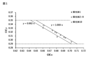
- the chromaticity coordinates of the emitted color are located between two straight lines represented by the following formulas (a) and (b) based on the coordinates represented by (x, y) in the CIE 1931 chromaticity coordinate system, and 0.290 ⁇ y ⁇ 0.350.
- y 0.992 - x ...
- y 1.000 - x ... (b)
- a red phosphor in ⁇ 18> in which the y value of the chromaticity coordinate of red light is 0.300 or more.
- ⁇ 20> A red phosphor in ⁇ 18> or ⁇ 19> above, in which the y value of the chromaticity coordinate of red light is 0.310 or less.
- a red phosphor comprising any one of ⁇ 18> to ⁇ 20> above, the phosphor being substantially free of Mn.
- ⁇ 22> A red phosphor according to any one of ⁇ 18> to ⁇ 21>, wherein the emission spectrum includes at least one emission peak having an emission peak wavelength of 648 nm or less.
- ⁇ 23> A red phosphor according to any one of ⁇ 18> to ⁇ 22> above, in which the internal quantum efficiency is 30% or more.
- (N, O) means containing N and O
- MA contains one or more elements selected from the group consisting of Sr, Ca, Ba, Na, K, Y, Gd, and La
- MB contains one or more elements selected from the group consisting of Li, Mg, and Zn
- MC' is Al
- MD contains one or more elements selected from the group consisting of Si, Ga, In, and Sc
- X contains one or more elements selected from the group consisting of F, Cl, Br, and I
- Re contains one or more elements selected from the group consisting of Eu, Ce, Pr, Tb, and Dy
- a, b, c, d
- Ix/Iy be equal to or less than the above upper limit, a phosphor with high phase purity and a narrow full width at half maximum (FWHM) in the emission spectrum can be obtained, improving the luminous efficiency of the light emitting device.
- the internal quantum efficiency of the red phosphor is 30% or more.
- the internal quantum efficiency is preferably 35% or more, more preferably 40% or more, even more preferably 45% or more, particularly preferably 50% or more, and even more preferably 55% or more. There is no upper limit, and the higher the better, but it is usually 100% or less.
- the internal quantum efficiency of the red phosphor can be determined by a conventional method, for example, it can be calculated from an emission spectrum measured using a spectrophotometer.
- Oxygen (O), nitrogen (N), and halogen elements (X) can be supplied by using oxides, nitrides, halides, etc. as phosphor raw materials that serve as the supply sources of each of the elements, and can also be appropriately contained by creating an oxygen- or nitrogen-containing atmosphere during the synthesis reaction.
- the material of the crucible is preferably one that does not react with the phosphor raw material or reactants, and examples of such materials include ceramics such as alumina, quartz, boron nitride, silicon carbide, and silicon nitride, metals such as nickel (Ni), platinum (Pt), molybdenum (Mo), tungsten (W), tantalum (Ta), niobium (Nb), iridium (Ir), and rhodium (Rh), and alloys containing these as the main components.
- ceramics such as alumina, quartz, boron nitride, silicon carbide, and silicon nitride
- metals such as nickel (Ni), platinum (Pt), molybdenum (Mo), tungsten (W), tantalum (Ta), niobium (Nb), iridium (Ir), and rhodium (Rh), and alloys containing these as the main components.
- the light emitting device has a first light emitting body (excitation light source), and can use a red phosphor that satisfies at least the above (A) and (B) as a second light emitting body.
- the configuration of the light emitting device is not limited, and any known device configuration can be used.
- the LED element may be fixed to a package such as a bullet-type package or an SMD-type package, or may be directly fixed on a circuit board as in the case of a chip-on-board type light-emitting device.
- a package such as a bullet-type package or an SMD-type package
- a circuit board such as a chip-on-board type light-emitting device.
- optical coupling between the LED element and the phosphor There is no limitation on the form of optical coupling between the LED element and the phosphor, and the space between them may simply be filled with a transparent medium (including air), or an optical element such as a lens, an optical fiber, a light guide plate, or a reflecting mirror may be interposed between them.
- the applications of the light-emitting device are not particularly limited, and the device can be used in various fields in which conventional light-emitting devices are used.
- light-emitting devices with high color rendering properties can be particularly suitably used as light sources for lighting devices and image display devices.
- a light emitting device including a red phosphor with a good emission wavelength can be used in a red vehicle indicator light or a white vehicle indicator light containing the red light.
- the present invention may provide an illumination device including the light-emitting device as a light source.
- the light emitting device is applied to a lighting device, there is no limitation on the specific configuration of the lighting device, and the light emitting device as described above may be appropriately incorporated into a known lighting device for use.
- a surface-emitting lighting device in which a number of light emitting devices are arranged on the bottom surface of a holding case may be mentioned.
- the present invention may provide an image display device including the light emitting device as a light source.
- the specific configuration of the image display device is not limited, but it is preferable to use the light emitting device together with a color filter.
- the image display device is a color image display device using a color liquid crystal display element
- the image display device can be formed by using the light emitting device as a backlight, and combining an optical shutter using liquid crystal and a color filter having red, green, and blue pixels.
- Quantum efficiency measurement The quantum efficiency was calculated based on the emission spectrum measured using a spectrofluorometer FP8500 (manufactured by JASCO Corporation) under the following measurement conditions.
- Light source Xenon lamp Excitation wavelength: 455 nm
- Phosphors 2 to 9 were obtained in the same manner as Phosphor 1, except that nitride raw materials containing Ga were appropriately used so that the phosphor had a composition shown in Table 1 and the firing temperature was set to 845°C.
- FIG. 1 shows the emission colors of the samples of phosphors 1 to 10 plotted based on the coordinates represented by (x, y) in the CIE chromaticity coordinates.
- Phosphors 1 and 10 are red phosphors that do not satisfy (B) above, because their CIE chromaticity coordinates do not lie between the two straight lines represented by formulas (a) and (b).
- phosphors 2 to 9 are red phosphors that satisfy (A) and (B) above.
- FIGS. 2A and 2B The relationship between the emission intensity and wavelength of phosphors 1 to 10 is shown in FIGS. 2A and 2B.
- phosphors 2 to 9 have dramatically improved emission intensities compared to phosphors 1 and 10.
- the normalized emission spectra of the above phosphor and a CASN phosphor (BR-101/J, manufactured by Mitsubishi Chemical Corporation) having an emission peak wavelength of 646 nm as a reference phosphor are shown in Fig. 3. From Fig. 3, it is understood that the phosphor according to the present invention has a good emission spectrum with a narrow half-width, and that phosphors 5, 8 and 9 have shorter emission peak wavelengths than phosphor 1 and the like.
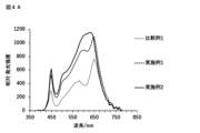
- FIGS. 4A to 4D show the results of simulating the relative emission intensity for the white LEDs of Comparative Examples 1, 3 to 4 and Examples 1 to 7 and 15, and Figures 5A to 5E show the results of simulating the relative emission intensity when the emission intensity at the emission peak wavelength of each white LED is set to 1.
- Table 2 also shows the results of determining the general color rendering index Ra, the red color rendering index R9, and the spectral efficiency (LER), which is the luminous flux (Lm) per energy (Wopt) of the emission spectrum and is an index of conversion efficiency, from each spectrum.
- Ra general color rendering index
- R9 red color rendering index
- LER spectral efficiency
- ratio/wt% refers to the weight percentage of each phosphor when the total weight of each phosphor is taken as 100%, with “green” being the LuAG phosphor, "red 1" being the first red phosphor, and “red 2" being the second red phosphor.
- FIGS. 5A and 7A show that the embodiment according to the present invention includes a well-balanced red and green range compared to Comparative Examples 1 and 2, resulting in improved spectral efficiency.
- the examples according to the embodiments of the present invention have preferable emission intensity in the red region compared to examples such as Comparative Example 4, thereby ensuring R9, and at the same time, they have succeeded in improving LER by suppressing emission intensity in the wavelength region of 660 nm or more, where the relative luminous efficiency is low, compared to Comparative Example 1, thereby obtaining a light-emitting device with good color rendering and conversion efficiency.
- Comparative Examples 2 and 6 with each example in Figures 7A and 7C, it can be seen that the same effect can be obtained even for emission colors that show different correlated color temperatures.
- Example 1 A simulation was performed in the same manner as in Example 1, except that a CASN phosphor (BR-101/J, manufactured by Mitsubishi Chemical Corporation) having an emission peak wavelength of 646 nm was used instead of the second red phosphor.
- 5D to 5E show the relative luminescence intensity in Reference Example 1 and the normalized relative luminescence intensity in each Example. Table 2 shows various characteristics of the white LED of Reference Example 1.
- the light-emitting device of the present invention has a sharp peak in the red region and is able to suppress the emission intensity in the wavelength region of 680 nm or more, where the relative luminous efficiency is low, and it is therefore possible to provide a light-emitting device that has high color rendering or red color reproducibility and high conversion efficiency.
- a phosphor that has a good emission peak wavelength, a narrow peak half-width in the emission spectrum, and/or high emission intensity, and by including this phosphor, it is possible to provide a light-emitting device, a lighting device, an image display device, and/or a vehicle indicator lamp that has good color rendering or color reproducibility and good conversion efficiency.
- the light-emitting device of the present invention has good color rendering, color reproducibility, conversion efficiency, safety, and contrast, and can therefore be used in lighting devices, image display devices, vehicle indicator lights, etc.
Landscapes
- Engineering & Computer Science (AREA)
- Physics & Mathematics (AREA)
- Chemical & Material Sciences (AREA)
- General Engineering & Computer Science (AREA)
- Optics & Photonics (AREA)
- Microelectronics & Electronic Packaging (AREA)
- Inorganic Chemistry (AREA)
- Materials Engineering (AREA)
- Organic Chemistry (AREA)
- Spectroscopy & Molecular Physics (AREA)
- General Physics & Mathematics (AREA)
- Luminescent Compositions (AREA)
- Led Device Packages (AREA)
- Optical Filters (AREA)
- Vessels And Coating Films For Discharge Lamps (AREA)
- Electroluminescent Light Sources (AREA)
- Arrangements Of Lighting Devices For Vehicle Interiors, Mounting And Supporting Thereof, Circuits Therefore (AREA)
Priority Applications (5)
| Application Number | Priority Date | Filing Date | Title |
|---|---|---|---|
| JP2024567195A JPWO2024142449A1 (https=) | 2022-12-27 | 2023-08-01 | |
| EP23911233.7A EP4646071A4 (en) | 2022-12-27 | 2023-08-01 | ELECTROLUMINESCENT DEVICE, LIGHTING DEVICE, IMAGE DISPLAY DEVICE AND VEHICLE INDICATOR LIGHT |
| CN202380045495.7A CN119344000A (zh) | 2022-12-27 | 2023-08-01 | 发光装置、照明装置、图像显示装置和车辆用显示灯 |
| KR1020247040396A KR20250008098A (ko) | 2022-12-27 | 2023-08-01 | 발광 장치, 조명 장치, 화상 표시 장치 및 차량용 표시등 |
| US18/971,929 US20250107316A1 (en) | 2022-12-27 | 2024-12-06 | Light-emitting device, illumination device, image display device, and indicator lamp for vehicle |
Applications Claiming Priority (2)
| Application Number | Priority Date | Filing Date | Title |
|---|---|---|---|
| JP2022210188 | 2022-12-27 | ||
| JP2022-210188 | 2022-12-27 |
Related Child Applications (1)
| Application Number | Title | Priority Date | Filing Date |
|---|---|---|---|
| US18/971,929 Continuation US20250107316A1 (en) | 2022-12-27 | 2024-12-06 | Light-emitting device, illumination device, image display device, and indicator lamp for vehicle |
Publications (1)
| Publication Number | Publication Date |
|---|---|
| WO2024142449A1 true WO2024142449A1 (ja) | 2024-07-04 |
Family
ID=91717162
Family Applications (1)
| Application Number | Title | Priority Date | Filing Date |
|---|---|---|---|
| PCT/JP2023/028194 Ceased WO2024142449A1 (ja) | 2022-12-27 | 2023-08-01 | 発光装置、照明装置、画像表示装置及び車両用表示灯 |
Country Status (7)
| Country | Link |
|---|---|
| US (1) | US20250107316A1 (https=) |
| EP (1) | EP4646071A4 (https=) |
| JP (3) | JPWO2024142449A1 (https=) |
| KR (1) | KR20250008098A (https=) |
| CN (1) | CN119344000A (https=) |
| TW (1) | TW202426812A (https=) |
| WO (1) | WO2024142449A1 (https=) |
Citations (5)
| Publication number | Priority date | Publication date | Assignee | Title |
|---|---|---|---|---|
| JP2006008721A (ja) | 2003-11-26 | 2006-01-12 | National Institute For Materials Science | 蛍光体と蛍光体を用いた発光器具 |
| JP2007291352A (ja) | 2006-03-27 | 2007-11-08 | Mitsubishi Chemicals Corp | 蛍光体及びそれを使用した発光装置 |
| JP2017008130A (ja) | 2015-06-16 | 2017-01-12 | 日亜化学工業株式会社 | 窒化物蛍光体、その製造方法及び発光装置 |
| JP2017155209A (ja) * | 2016-02-29 | 2017-09-07 | 日亜化学工業株式会社 | 窒化物蛍光体の製造方法、窒化物蛍光体及び発光装置 |
| WO2019188319A1 (ja) * | 2018-03-27 | 2019-10-03 | デンカ株式会社 | 蛍光体及びそれを用いた発光装置 |
Family Cites Families (1)
| Publication number | Priority date | Publication date | Assignee | Title |
|---|---|---|---|---|
| CN116987502B (zh) * | 2022-01-20 | 2024-12-31 | 三菱化学株式会社 | 荧光体、发光装置、照明装置、图像显示装置和车辆用显示灯 |
-
2023
- 2023-08-01 EP EP23911233.7A patent/EP4646071A4/en active Pending
- 2023-08-01 WO PCT/JP2023/028194 patent/WO2024142449A1/ja not_active Ceased
- 2023-08-01 JP JP2024567195A patent/JPWO2024142449A1/ja active Pending
- 2023-08-01 KR KR1020247040396A patent/KR20250008098A/ko active Pending
- 2023-08-01 CN CN202380045495.7A patent/CN119344000A/zh active Pending
- 2023-08-08 TW TW112129697A patent/TW202426812A/zh unknown
-
2024
- 2024-04-03 JP JP2024060243A patent/JP2024094337A/ja active Pending
- 2024-04-03 JP JP2024060242A patent/JP2024094336A/ja active Pending
- 2024-12-06 US US18/971,929 patent/US20250107316A1/en active Pending
Patent Citations (5)
| Publication number | Priority date | Publication date | Assignee | Title |
|---|---|---|---|---|
| JP2006008721A (ja) | 2003-11-26 | 2006-01-12 | National Institute For Materials Science | 蛍光体と蛍光体を用いた発光器具 |
| JP2007291352A (ja) | 2006-03-27 | 2007-11-08 | Mitsubishi Chemicals Corp | 蛍光体及びそれを使用した発光装置 |
| JP2017008130A (ja) | 2015-06-16 | 2017-01-12 | 日亜化学工業株式会社 | 窒化物蛍光体、その製造方法及び発光装置 |
| JP2017155209A (ja) * | 2016-02-29 | 2017-09-07 | 日亜化学工業株式会社 | 窒化物蛍光体の製造方法、窒化物蛍光体及び発光装置 |
| WO2019188319A1 (ja) * | 2018-03-27 | 2019-10-03 | デンカ株式会社 | 蛍光体及びそれを用いた発光装置 |
Non-Patent Citations (5)
| Title |
|---|
| CHEMISTRY LETTERS, vol. 35, no. 3, 2006, pages 334 - 335 |
| CHEMISTRY OF MATERIALS, vol. 31, no. 12, 2019, pages 4614 - 4618 |
| FANG MU-HUAI, MENG SHU-YI, MAJEWSKA NATALIA, LEŚNIEWSKI TADEUSZ, MAHLIK SEBASTIAN, GRINBERG MAREK, SHEU HWO-SHUENN, LIU RU-SHI: "Chemical Control of SrLi(Al 1– x Ga x ) 3 N 4 :Eu 2+ Red Phosphors at Extreme Conditions for Application in Light-Emitting Diodes", CHEMISTRY OF MATERIALS, AMERICAN CHEMICAL SOCIETY, US, vol. 31, no. 12, 25 June 2019 (2019-06-25), US , pages 4614 - 4618, XP093079711, ISSN: 0897-4756, DOI: 10.1021/acs.chemmater.9b01783 * |
| J. MATER. CHEM. C, vol. 3, 2015, pages 5484 - 5489 |
| See also references of EP4646071A4 |
Also Published As
| Publication number | Publication date |
|---|---|
| TW202426812A (zh) | 2024-07-01 |
| CN119344000A (zh) | 2025-01-21 |
| JP2024094337A (ja) | 2024-07-09 |
| KR20250008098A (ko) | 2025-01-14 |
| US20250107316A1 (en) | 2025-03-27 |
| JPWO2024142449A1 (https=) | 2024-07-04 |
| EP4646071A1 (en) | 2025-11-05 |
| JP2024094336A (ja) | 2024-07-09 |
| EP4646071A4 (en) | 2026-04-08 |
Similar Documents
| Publication | Publication Date | Title |
|---|---|---|
| KR102599819B1 (ko) | 형광체, 발광 장치, 조명 장치, 화상 표시 장치 및 차량용 표시등 | |
| KR102599818B1 (ko) | 형광체, 발광 장치, 조명 장치, 화상 표시 장치 및 차량용 표시등 | |
| JP7311866B1 (ja) | 蛍光体 | |
| JP2024129649A (ja) | 蛍光体、発光装置、照明装置、画像表示装置及び車両用表示灯 | |
| JP7311867B1 (ja) | 蛍光体 | |
| JP7464959B1 (ja) | 発光装置、照明装置、画像表示装置及び車両用表示灯 | |
| WO2023139824A1 (ja) | 蛍光体、発光装置、照明装置、画像表示装置及び車両用表示灯 | |
| WO2024142449A1 (ja) | 発光装置、照明装置、画像表示装置及び車両用表示灯 | |
| JP7369410B1 (ja) | 蛍光体、発光装置、照明装置、画像表示装置及び車両用表示灯 | |
| JP7369409B1 (ja) | 蛍光体、発光装置、照明装置、画像表示装置及び車両用表示灯 | |
| JP7253214B1 (ja) | 発光装置、照明装置、画像表示装置及び車両用表示灯 | |
| JP2024129648A (ja) | 蛍光体、発光装置、照明装置、画像表示装置及び車両用表示灯 | |
| WO2025105489A1 (ja) | 蛍光体、発光装置、照明装置、画像表示装置及び車両用表示灯 | |
| WO2023063251A1 (ja) | 蛍光体、発光装置、照明装置、画像表示装置及び車両用表示灯 | |
| JP2023057391A (ja) | 蛍光体 | |
| WO2023139823A1 (ja) | 蛍光体、発光装置、照明装置、画像表示装置及び車両用表示灯 | |
| CN118043979A (zh) | 荧光体、发光装置、照明装置、图像显示装置和车辆用显示灯 |
Legal Events
| Date | Code | Title | Description |
|---|---|---|---|
| 121 | Ep: the epo has been informed by wipo that ep was designated in this application |
Ref document number: 23911233 Country of ref document: EP Kind code of ref document: A1 |
|
| ENP | Entry into the national phase |
Ref document number: 20247040396 Country of ref document: KR Kind code of ref document: A |
|
| WWE | Wipo information: entry into national phase |
Ref document number: 1020247040396 Country of ref document: KR |
|
| WWE | Wipo information: entry into national phase |
Ref document number: 202380045495.7 Country of ref document: CN |
|
| WWP | Wipo information: published in national office |
Ref document number: 202380045495.7 Country of ref document: CN |
|
| WWE | Wipo information: entry into national phase |
Ref document number: 2024567195 Country of ref document: JP |
|
| WWE | Wipo information: entry into national phase |
Ref document number: 2023911233 Country of ref document: EP |
|
| NENP | Non-entry into the national phase |
Ref country code: DE |
|
| ENP | Entry into the national phase |
Ref document number: 2023911233 Country of ref document: EP Effective date: 20250728 |
|
| ENP | Entry into the national phase |
Ref document number: 2023911233 Country of ref document: EP Effective date: 20250728 |
|
| WWP | Wipo information: published in national office |
Ref document number: 2023911233 Country of ref document: EP |