WO2024142152A1 - 光伝送路及び接続方法 - Google Patents
光伝送路及び接続方法 Download PDFInfo
- Publication number
- WO2024142152A1 WO2024142152A1 PCT/JP2022/047896 JP2022047896W WO2024142152A1 WO 2024142152 A1 WO2024142152 A1 WO 2024142152A1 JP 2022047896 W JP2022047896 W JP 2022047896W WO 2024142152 A1 WO2024142152 A1 WO 2024142152A1
- Authority
- WO
- WIPO (PCT)
- Prior art keywords
- optical fiber
- core optical
- fiber transmission
- transmission lines
- core
- Prior art date
- Legal status (The legal status is an assumption and is not a legal conclusion. Google has not performed a legal analysis and makes no representation as to the accuracy of the status listed.)
- Ceased
Links
Images


Classifications
-
- G—PHYSICS
- G02—OPTICS
- G02B—OPTICAL ELEMENTS, SYSTEMS OR APPARATUS
- G02B6/00—Light guides; Structural details of arrangements comprising light guides and other optical elements, e.g. couplings
- G02B6/24—Coupling light guides
- G02B6/26—Optical coupling means
- G02B6/35—Optical coupling means having switching means
-
- G—PHYSICS
- G02—OPTICS
- G02B—OPTICAL ELEMENTS, SYSTEMS OR APPARATUS
- G02B6/00—Light guides; Structural details of arrangements comprising light guides and other optical elements, e.g. couplings
- G02B6/24—Coupling light guides
- G02B6/36—Mechanical coupling means
- G02B6/38—Mechanical coupling means having fibre to fibre mating means
Definitions
- Figure 1 shows an example of connecting multiple multi-core optical fiber transmission lines.
- 103 indicates a multi-core optical fiber transmission line
- 106 indicates a core
- 107 indicates a marker.
- the optical transmission line of the present disclosure is A plurality of multi-core optical fiber transmission lines; two input/output devices arranged at both ends of the plurality of multi-core optical fiber transmission lines for inputting and outputting light to and from a plurality of cores of the multi-core optical fiber transmission lines; a switching connection device that is disposed between any of the multi-core optical fiber transmission lines and switches and connects each of the cores of the multi-core optical fiber transmission lines; Equipped with.
- the optical transmission line 100 of this embodiment includes a plurality of multi-core optical fiber transmission lines 103, two input/output devices 102, 104 arranged at both ends of the plurality of multi-core optical fiber transmission lines 103 for inputting and outputting light to the plurality of cores of the multi-core optical fiber transmission lines 103, and a switching connection device 110 arranged between the multi-core optical fiber transmission lines 103 and the input/output devices 104 for switching and connecting each core of the multi-core optical fiber transmission lines 103 to each core of the multi-core optical fiber of the input/output device 104.
- any cores of the multiple multi-core optical fiber transmission lines 103 are connected to each other, and at the other end of the multiple connected multi-core optical fiber transmission lines 103, a switching connection device 110 is used to switch and connect so that the channel of the input/output device 104 matches the channel of the input/output device 102.
- each channel 101 of the input/output device 102 and each channel 105 of the input/output device 104 can be made to correspond to the desired relationship.
- any cores of multiple multi-core optical fiber transmission lines 103 can be connected to each other, thereby shortening the connection time. This leads to cost reductions during the construction and operation of the optical transmission lines.
- FIG. 4 An example of the configuration of the switching connection device 110 of this embodiment is shown in FIG. 4.
- 110 is a switching connection device
- 111 and 112 are multi-core optical fibers
- 114 and 115 are ferrules.
- the switching connection device 110 switches and connects each core arranged on a concentric circle of one multi-core optical fiber 111 to each core arranged on a concentric circle of the opposing other multi-core optical fiber 112 by rotating the one multi-core optical fiber 111 around its axis at the center.
- the ferrule 115 that houses the other multi-core optical fiber 112 is fixed, the far end of the one multi-core optical fiber 111 is fixed, and the ferrule 114 is rotated around the center of the one multi-core optical fiber 111.
- the end face of the ferrule 114 and the end face of the ferrule 115 are separated from each other, but it is preferable to bring the end faces as close as possible to each other.
- One multi-core optical fiber 111 may be connected to the input/output device 104 in FIG. 2, and the other multi-core optical fiber 112 may be connected to the multi-core optical fiber transmission line 103 in FIG. 2, or the connection relationship may be reversed. Also, one multi-core optical fiber 111 may be connected to the input/output device 102 in FIG. 2, and the other multi-core optical fiber 112 may be connected to the multi-core optical fiber transmission line 103 in FIG. 2, or the connection relationship may be reversed. Furthermore, the switching connection device 110 may be disposed between any of the multi-core optical fiber transmission lines 103 in FIG. 2, and one multi-core optical fiber 111 and the other multi-core optical fiber 112 may be connected to the multi-core optical fiber transmission line 103, respectively.
- the optical transmission line and connection method disclosed herein can connect any cores of multiple multi-core optical fiber transmission lines, regardless of the presence or absence of markers in the multi-core optical fiber transmission lines. Therefore, the connection time of multiple multi-core optical fiber transmission lines can be shortened.
- Optical transmission path 101 Each channel 102: Input/output device 103: Multi-core optical fiber transmission path 104: Input/output device 105: Each channel 106: Core 107: Marker 110: Switching connection device 111: Multi-core optical fiber 112: Multi-core optical fiber 113: Equal magnification image lens 114: Ferrule 115: Ferrule
Landscapes
- Physics & Mathematics (AREA)
- General Physics & Mathematics (AREA)
- Optics & Photonics (AREA)
- Mechanical Coupling Of Light Guides (AREA)
Abstract
本開示は、複数のマルチコア光ファイバ伝送路と、前記複数のマルチコア光ファイバ伝送路の両端に配置され、前記マルチコア光ファイバ伝送路の複数のコアに光を入出力する2つの入出力デバイスと、前記マルチコア光ファイバ伝送路と前記入出力デバイスとの間に配置され、前記マルチコア光ファイバ伝送路の各コアと前記入出力デバイスのマルチコア光ファイバの各コアとを切替接続する切替接続デバイスと、を備える光伝送路である。
Description
本開示は、マルチコア光ファイバ伝送路の接続に関する。
非結合型のマルチコア光ファイバは、将来の大容量光通信を実現する光ファイバとして有力視されている(例えば、特許文献1参照)。マルチコア光ファイバはクラッド内に複数のコアを有する。各コアを識別するために、コア番号識別用のマーカを配置することがある。マーカとの位置関係によって、コア番号を把握することができる。
複数のマルチコア光ファイバ伝送路を接続する例を図1に示す。図1において、103はマルチコア光ファイバ伝送路、106はコア、107はマーカを示す。複数のマルチコア光ファイバ伝送路103を接続する場合は、各接続点でマーカ107の位置を一致させることで、複数のマルチコア光ファイバ伝送路103の両端の入出力デバイスで所定のチャネルに光を入出力することができる。
しかし、複数のマルチコア光ファイバ伝送路103を接続しようとすると、各接続点でマーカ107の位置合わせをした上で、マルチコア光ファイバ伝送路103を接続しなければならず、光伝送路の建設や運用に多大な時間を要することになる。これは、光伝送路の建設時や運用時のコスト増大につながる。
本開示は、上記事情を鑑みてなされてものであり、複数のマルチコア光ファイバ伝送路の接続時間を短縮することのできる光伝送路及び接続方法を提供することを目的とする。
上記目的を達成するために、本開示の光伝送路及び接続方法では、マルチコア光ファイバ伝送路のマーカの有無に関わらず、マーカの位置を確認することなく、複数のマルチコア光ファイバ伝送路を接続し、マルチコア光ファイバ伝送路と入出力デバイスの間に切替接続デバイスを配置し、マルチコア光ファイバ伝送路の各コアと切替接続デバイスのマルチコア光ファイバの各コアとを切替接続することとした。
具体的には、本開示の光伝送路は、
複数のマルチコア光ファイバ伝送路と、
前記複数のマルチコア光ファイバ伝送路の両端に配置され、前記マルチコア光ファイバ伝送路の複数のコアに光を入出力する2つの入出力デバイスと、
前記マルチコア光ファイバ伝送路と前記入出力デバイスとの間に配置され、前記マルチコア光ファイバ伝送路の各コアと前記入出力デバイスのマルチコア光ファイバの各コアとを切替接続する切替接続デバイスと、
を備える。
複数のマルチコア光ファイバ伝送路と、
前記複数のマルチコア光ファイバ伝送路の両端に配置され、前記マルチコア光ファイバ伝送路の複数のコアに光を入出力する2つの入出力デバイスと、
前記マルチコア光ファイバ伝送路と前記入出力デバイスとの間に配置され、前記マルチコア光ファイバ伝送路の各コアと前記入出力デバイスのマルチコア光ファイバの各コアとを切替接続する切替接続デバイスと、
を備える。
具体的には、本開示の接続方法は、
複数のマルチコア光ファイバ伝送路と、
前記複数のマルチコア光ファイバ伝送路の両端に配置され、前記マルチコア光ファイバ伝送路の複数のコアに光を入出力する2つの入出力デバイスと、
の接続方法であって、
前記マルチコア光ファイバ伝送路と前記入出力デバイスとの間で、前記マルチコア光ファイバ伝送路の各コアと前記入出力デバイスのマルチコア光ファイバの各コアとを切替接続する。
複数のマルチコア光ファイバ伝送路と、
前記複数のマルチコア光ファイバ伝送路の両端に配置され、前記マルチコア光ファイバ伝送路の複数のコアに光を入出力する2つの入出力デバイスと、
の接続方法であって、
前記マルチコア光ファイバ伝送路と前記入出力デバイスとの間で、前記マルチコア光ファイバ伝送路の各コアと前記入出力デバイスのマルチコア光ファイバの各コアとを切替接続する。
上記目的を達成するために、本開示の光伝送路及び接続方法では、マルチコア光ファイバ伝送路のマーカの有無に関わらず、マーカの位置を確認することなく、複数のマルチコア光ファイバ伝送路を接続する際に、マルチコア光ファイバのいずれかの間に切替接続デバイスを配置し、マルチコア光ファイバ伝送路の各コア同士を切替接続することとした。
具体的には、本開示の光伝送路は、
複数のマルチコア光ファイバ伝送路と、
前記複数のマルチコア光ファイバ伝送路の両端に配置され、前記マルチコア光ファイバ伝送路の複数のコアに光を入出力する2つの入出力デバイスと、
前記マルチコア光ファイバ伝送路のいずれかの間に配置され、前記マルチコア光ファイバ伝送路の各コア同士を切替接続する切替接続デバイスと、
を備える。
複数のマルチコア光ファイバ伝送路と、
前記複数のマルチコア光ファイバ伝送路の両端に配置され、前記マルチコア光ファイバ伝送路の複数のコアに光を入出力する2つの入出力デバイスと、
前記マルチコア光ファイバ伝送路のいずれかの間に配置され、前記マルチコア光ファイバ伝送路の各コア同士を切替接続する切替接続デバイスと、
を備える。
具体的には、本開示の接続方法は、
複数のマルチコア光ファイバ伝送路と、
前記複数のマルチコア光ファイバ伝送路の両端に配置され、前記マルチコア光ファイバ伝送路の複数のコアに光を入出力する2つの入出力デバイスと、
の接続方法であって、
前記マルチコア光ファイバ伝送路のいずれかの間で、前記マルチコア光ファイバ伝送路の各コア同士を切替接続する。
複数のマルチコア光ファイバ伝送路と、
前記複数のマルチコア光ファイバ伝送路の両端に配置され、前記マルチコア光ファイバ伝送路の複数のコアに光を入出力する2つの入出力デバイスと、
の接続方法であって、
前記マルチコア光ファイバ伝送路のいずれかの間で、前記マルチコア光ファイバ伝送路の各コア同士を切替接続する。
本開示の光伝送路の切替接続デバイスは、
一方のマルチコア光ファイバの同心円上に配置された各コアと対向する他方のマルチコア光ファイバの同心円上に配置された各コアとを、一方のマルチコア光ファイバの中心を軸とする回転によって切替接続することを特徴とする。
一方のマルチコア光ファイバの同心円上に配置された各コアと対向する他方のマルチコア光ファイバの同心円上に配置された各コアとを、一方のマルチコア光ファイバの中心を軸とする回転によって切替接続することを特徴とする。
なお、上記各開示は、可能な限り組み合わせることができる。
本開示は、複数のマルチコア光ファイバ伝送路の接続時間を短縮することのできる光伝送路及び接続方法を提供することができる。
以下、本開示の実施形態について、図面を参照しながら詳細に説明する。なお、本開示は、以下に示す実施形態に限定されるものではない。これらの実施の例は例示に過ぎず、本開示は当業者の知識に基づいて種々の変更、改良を施した形態で実施することができる。なお、本明細書及び図面において符号が同じ構成要素は、相互に同一のものを示すものとする。
本実施形態に係る光伝送路の構成例を図2に示す。図2において、100は光伝送路、101は各チャネル、102は入出力デバイス、103はマルチコア光ファイバ伝送路、104は入出力デバイス、105は各チャネル、110は切替接続デバイスである。
本実施形態の光伝送路100は、複数のマルチコア光ファイバ伝送路103と、複数のマルチコア光ファイバ伝送路103の両端に配置され、マルチコア光ファイバ伝送路103の複数のコアに光を入出力する2つの入出力デバイス102、104と、マルチコア光ファイバ伝送路103と入出力デバイスと104の間に配置され、マルチコア光ファイバ伝送路103の各コアと入出力デバイス104のマルチコア光ファイバの各コアとを切替接続する切替接続デバイス110と、を備える。
本実施形態の光伝送路及び接続方法では、マルチコア光ファイバ伝送路103のマーカの有無に関わらず、複数のマルチコア光ファイバ伝送路103の任意のコア同士を接続する。複数のマルチコア光ファイバ伝送路103の両端には、マルチコア光ファイバ伝送路103の複数のコアに光を入出力する2つの入出力デバイス102及び104を配置する。マルチコア光ファイバ伝送路103と入出力デバイス104との間に切替接続デバイス110を配置し、マルチコア光ファイバ伝送路103の各コアと切替接続デバイス110のマルチコア光ファイバの各コアとを切替接続する。
マーカの有無に関わらず、複数のマルチコア光ファイバ伝送路103の任意のコア同士を接続し、接続された複数のマルチコア光ファイバ伝送路103の他端では、入出力デバイス104のチャネルが入出力デバイス102のチャネルに整合するよう、切替接続デバイス110で切替接続する。
なお、各チャネル101及び105は複数のシングルコア光ファイバのコアや、光導波回路の複数の導波路、マルチコア光ファイバの複数のコアである。
切替接続デバイス110は、マルチコア光ファイバ伝送路103と入出力デバイスと102の間に配置されてもよいし、両方に配置されてもよい。また、切替接続デバイス110は、マルチコア光ファイバ伝送路103のいずれかの間に配置されてもよい。少なくとも1か所に配置されればよい。切替接続デバイス110をマルチコア光ファイバ伝送路103のいずれかの間に配置する場合は、切替接続デバイス110は、マルチコア光ファイバ伝送路の各コア同士を切替接続する。
切替接続デバイス110でコアを切替接続すると、入出力デバイス102の各チャネル101と入出力デバイス104の各チャネル105を所望の対応関係とすることができる。マルチコア光ファイバ伝送路103のマーカの有無に関わらず、複数のマルチコア光ファイバ伝送路103の任意のコア同士を接続できるので、接続時間を短縮することができる。これは、光伝送路の建設時や運用時のコスト圧縮につながる。
本実施形態の切替接続デバイス110の構成例を図3に示す。図3において、110は切替接続デバイス、111、112はマルチコア光ファイバ、113は等倍像レンズである。
切替接続デバイス110は、一方のマルチコア光ファイバ111の同心円上に配置された各コアと対向する他方のマルチコア光ファイバ112の同心円上に配置された各コアとを、一方のマルチコア光ファイバ111の中心を軸とする回転によって切替接続する。他方のマルチコア光ファイバ112を固定し、一方のマルチコア光ファイバ111の遠端を固定し、一方のマルチコア光ファイバ111の中心を軸として、マルチコア光ファイバ111の等倍像レンズ113の側を捻じるように回転させる。等倍像レンズ113は一方のマルチコア光ファイバ111のコア像を他方のマルチコア光ファイバ112のコアに正転又は反転で等倍に投影する。逆方向にも正転又は反転で等倍に投影する。
一方のマルチコア光ファイバ111を図2の入出力デバイス104に接続し、他方のマルチコア光ファイバ112を図2のマルチコア光ファイバ伝送路103に接続してもよいし、接続関係を反対にしてもよい。また、一方のマルチコア光ファイバ111を図2の入出力デバイス102に接続し、他方のマルチコア光ファイバ112を図2のマルチコア光ファイバ伝送路103に接続してもよいし、接続関係を反対にしてもよい。さらに、切替接続デバイス110を図2のいずれかのマルチコア光ファイバ伝送路103の間に配置し、一方のマルチコア光ファイバ111及び他方のマルチコア光ファイバ112をそれぞれマルチコア光ファイバ伝送路103に接続してもよい。
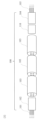
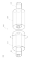
本実施形態の切替接続デバイス110の構成例を図4に示す。図4において、110は切替接続デバイス、111、112はマルチコア光ファイバ、114、115はフェルールである。
切替接続デバイス110は、一方のマルチコア光ファイバ111の同心円上に配置された各コアと対向する他方のマルチコア光ファイバ112の同心円上に配置された各コアとを、一方のマルチコア光ファイバ111の中心を軸とする回転によって切替接続する。他方のマルチコア光ファイバ112を収容するフェルール115を固定し、一方のマルチコア光ファイバ111の遠端を固定し、一方のマルチコア光ファイバ111の中心を軸として、フェルール114を回転させる。図4では、フェルール114の端面とフェルール115の端面は離れているが、できる限り端面同士は近づける方が好ましい。
一方のマルチコア光ファイバ111を図2の入出力デバイス104に接続し、他方のマルチコア光ファイバ112を図2のマルチコア光ファイバ伝送路103に接続してもよいし、接続関係を反対にしてもよい。また、一方のマルチコア光ファイバ111を図2の入出力デバイス102に接続し、他方のマルチコア光ファイバ112を図2のマルチコア光ファイバ伝送路103に接続してもよいし、接続関係を反対にしてもよい。さらに、切替接続デバイス110を図2のいずれかのマルチコア光ファイバ伝送路103の間に配置し、一方のマルチコア光ファイバ111及び他方のマルチコア光ファイバ112をそれぞれマルチコア光ファイバ伝送路103に接続してもよい。
以上説明したように、本開示の光伝送路及び接続方法では、マルチコア光ファイバ伝送路のマーカの有無に関わらず、複数のマルチコア光ファイバ伝送路の任意のコア同士を接続することができる。従って、複数のマルチコア光ファイバ伝送路の接続時間を短縮することができる。
100:光伝送路
101:各チャネル
102:入出力デバイス
103:マルチコア光ファイバ伝送路
104:入出力デバイス
105:各チャネル
106:コア
107:マーカ
110:切替接続デバイス
111:マルチコア光ファイバ
112:マルチコア光ファイバ
113:等倍像レンズ
114:フェルール
115:フェルール
101:各チャネル
102:入出力デバイス
103:マルチコア光ファイバ伝送路
104:入出力デバイス
105:各チャネル
106:コア
107:マーカ
110:切替接続デバイス
111:マルチコア光ファイバ
112:マルチコア光ファイバ
113:等倍像レンズ
114:フェルール
115:フェルール
Claims (5)
- 複数のマルチコア光ファイバ伝送路と、
前記複数のマルチコア光ファイバ伝送路の両端に配置され、前記マルチコア光ファイバ伝送路の複数のコアに光を入出力する2つの入出力デバイスと、
前記マルチコア光ファイバ伝送路と前記入出力デバイスとの間に配置され、前記マルチコア光ファイバ伝送路の各コアと前記入出力デバイスのマルチコア光ファイバの各コアとを切替接続する切替接続デバイスと、
を備える光伝送路。 - 複数のマルチコア光ファイバ伝送路と、
前記複数のマルチコア光ファイバ伝送路の両端に配置され、前記マルチコア光ファイバ伝送路の複数のコアに光を入出力する2つの入出力デバイスと、
前記マルチコア光ファイバ伝送路のいずれかの間に配置され、前記マルチコア光ファイバ伝送路の各コア同士を切替接続する切替接続デバイスと、
を備える光伝送路。 - 前記切替接続デバイスは、一方のマルチコア光ファイバの同心円上に配置された各コアと対向する他方のマルチコア光ファイバの同心円上に配置された各コアとを、一方のマルチコア光ファイバの中心を軸とする回転によって切替接続することを特徴とする請求項1又は2に記載の光伝送路。
- 複数のマルチコア光ファイバ伝送路と、
前記複数のマルチコア光ファイバ伝送路の両端に配置され、前記マルチコア光ファイバ伝送路の複数のコアに光を入出力する2つの入出力デバイスと、
の接続方法であって、
前記マルチコア光ファイバ伝送路と前記入出力デバイスとの間で、前記マルチコア光ファイバ伝送路の各コアと前記入出力デバイスのマルチコア光ファイバの各コアとを切替接続する接続方法。 - 複数のマルチコア光ファイバ伝送路と、
前記複数のマルチコア光ファイバ伝送路の両端に配置され、前記マルチコア光ファイバ伝送路の複数のコアに光を入出力する2つの入出力デバイスと、
の接続方法であって、
前記マルチコア光ファイバ伝送路のいずれかの間で、前記マルチコア光ファイバ伝送路の各コア同士を切替接続する接続方法。
Priority Applications (2)
| Application Number | Priority Date | Filing Date | Title |
|---|---|---|---|
| PCT/JP2022/047896 WO2024142152A1 (ja) | 2022-12-26 | 2022-12-26 | 光伝送路及び接続方法 |
| JP2024566942A JPWO2024142152A1 (ja) | 2022-12-26 | 2022-12-26 |
Applications Claiming Priority (1)
| Application Number | Priority Date | Filing Date | Title |
|---|---|---|---|
| PCT/JP2022/047896 WO2024142152A1 (ja) | 2022-12-26 | 2022-12-26 | 光伝送路及び接続方法 |
Publications (1)
| Publication Number | Publication Date |
|---|---|
| WO2024142152A1 true WO2024142152A1 (ja) | 2024-07-04 |
Family
ID=91716927
Family Applications (1)
| Application Number | Title | Priority Date | Filing Date |
|---|---|---|---|
| PCT/JP2022/047896 Ceased WO2024142152A1 (ja) | 2022-12-26 | 2022-12-26 | 光伝送路及び接続方法 |
Country Status (2)
| Country | Link |
|---|---|
| JP (1) | JPWO2024142152A1 (ja) |
| WO (1) | WO2024142152A1 (ja) |
Citations (4)
| Publication number | Priority date | Publication date | Assignee | Title |
|---|---|---|---|---|
| JPH0282212A (ja) * | 1988-09-20 | 1990-03-22 | Fujitsu Ltd | 光スイッチ |
| JP2016082318A (ja) * | 2014-10-14 | 2016-05-16 | 日本電信電話株式会社 | 光伝送システム |
| WO2022018783A1 (ja) * | 2020-07-20 | 2022-01-27 | 日本電信電話株式会社 | 光スイッチ |
| US20220276444A1 (en) * | 2021-02-26 | 2022-09-01 | Viavi Solutions Inc. | Fiber-optic switches using multicore optical fibers |
-
2022
- 2022-12-26 JP JP2024566942A patent/JPWO2024142152A1/ja active Pending
- 2022-12-26 WO PCT/JP2022/047896 patent/WO2024142152A1/ja not_active Ceased
Patent Citations (4)
| Publication number | Priority date | Publication date | Assignee | Title |
|---|---|---|---|---|
| JPH0282212A (ja) * | 1988-09-20 | 1990-03-22 | Fujitsu Ltd | 光スイッチ |
| JP2016082318A (ja) * | 2014-10-14 | 2016-05-16 | 日本電信電話株式会社 | 光伝送システム |
| WO2022018783A1 (ja) * | 2020-07-20 | 2022-01-27 | 日本電信電話株式会社 | 光スイッチ |
| US20220276444A1 (en) * | 2021-02-26 | 2022-09-01 | Viavi Solutions Inc. | Fiber-optic switches using multicore optical fibers |
Also Published As
| Publication number | Publication date |
|---|---|
| JPWO2024142152A1 (ja) | 2024-07-04 |
Similar Documents
| Publication | Publication Date | Title |
|---|---|---|
| US8295667B2 (en) | Hole arranged photonic crystal fiber for low loss, tight fiber bending applications | |
| JP4248495B2 (ja) | 光学偏光モジュールとシステム | |
| US6442310B1 (en) | Optical coupling device and method | |
| WO2022176978A1 (ja) | 光入出力装置 | |
| CN111801612B (zh) | 光学连接部件 | |
| CN104932061A (zh) | 光纤连接器 | |
| US10775566B2 (en) | Fiber optic lane changers for use with fiber optic cables having unused optical fibers and related methods | |
| EP0013972A1 (en) | Tapered mixing rod for a fiber optical multi-port coupler | |
| Wlodawski et al. | A new generation of ultra-dense optical I/O for silicon photonics | |
| WO2024142152A1 (ja) | 光伝送路及び接続方法 | |
| WO2022018783A1 (ja) | 光スイッチ | |
| JP7476986B2 (ja) | 光クロスコネクト装置 | |
| JP5916126B2 (ja) | 光ファイバ心線切替装置およびその方法 | |
| JPH08313744A (ja) | 光回路部品 | |
| US5390267A (en) | Optical fiber/terminal connecting device | |
| Brückner | Fiber Optic Connections and Couplers | |
| JP7828018B2 (ja) | 光クロスコネクト装置及びその製造方法 | |
| JP4062110B2 (ja) | 光接続部品及び光接続方法並びに光通信機器 | |
| WO2023067772A1 (ja) | 光接続モジュール | |
| US20230400641A1 (en) | Optical connection device, composite optical connection device, and manufacturing method of optical connection device | |
| CN116931200B (zh) | 一种400g dr4光器件 | |
| KR102824039B1 (ko) | 하이브리드 광섬유 융착 접속기 | |
| JPH06347670A (ja) | 光配線部品 | |
| WO2024075219A1 (ja) | 光クロスコネクトユニット、光クロスコネクト装置、及び、ノード | |
| WO2024169176A1 (zh) | 多纤芯连接装置、分光组件和分光系统 |
Legal Events
| Date | Code | Title | Description |
|---|---|---|---|
| 121 | Ep: the epo has been informed by wipo that ep was designated in this application |
Ref document number: 22969946 Country of ref document: EP Kind code of ref document: A1 |
|
| WWE | Wipo information: entry into national phase |
Ref document number: 2024566942 Country of ref document: JP |
|
| NENP | Non-entry into the national phase |
Ref country code: DE |
|
| 122 | Ep: pct application non-entry in european phase |
Ref document number: 22969946 Country of ref document: EP Kind code of ref document: A1 |