WO2024135846A1 - 混注制御装置、混注システム、混注制御プログラム - Google Patents
混注制御装置、混注システム、混注制御プログラム Download PDFInfo
- Publication number
- WO2024135846A1 WO2024135846A1 PCT/JP2023/046251 JP2023046251W WO2024135846A1 WO 2024135846 A1 WO2024135846 A1 WO 2024135846A1 JP 2023046251 W JP2023046251 W JP 2023046251W WO 2024135846 A1 WO2024135846 A1 WO 2024135846A1
- Authority
- WO
- WIPO (PCT)
- Prior art keywords
- infusion
- unit
- preparation data
- vial
- control unit
- Prior art date
- Legal status (The legal status is an assumption and is not a legal conclusion. Google has not performed a legal analysis and makes no representation as to the accuracy of the status listed.)
- Ceased
Links
Images






Classifications
-
- A—HUMAN NECESSITIES
- A61—MEDICAL OR VETERINARY SCIENCE; HYGIENE
- A61J—CONTAINERS SPECIALLY ADAPTED FOR MEDICAL OR PHARMACEUTICAL PURPOSES; DEVICES OR METHODS SPECIALLY ADAPTED FOR BRINGING PHARMACEUTICAL PRODUCTS INTO PARTICULAR PHYSICAL OR ADMINISTERING FORMS; DEVICES FOR ADMINISTERING FOOD OR MEDICINES ORALLY; BABY COMFORTERS; DEVICES FOR RECEIVING SPITTLE
- A61J3/00—Devices or methods specially adapted for bringing pharmaceutical products into particular physical or administering forms
-
- G—PHYSICS
- G16—INFORMATION AND COMMUNICATION TECHNOLOGY [ICT] SPECIALLY ADAPTED FOR SPECIFIC APPLICATION FIELDS
- G16H—HEALTHCARE INFORMATICS, i.e. INFORMATION AND COMMUNICATION TECHNOLOGY [ICT] SPECIALLY ADAPTED FOR THE HANDLING OR PROCESSING OF MEDICAL OR HEALTHCARE DATA
- G16H20/00—ICT specially adapted for therapies or health-improving plans, e.g. for handling prescriptions, for steering therapy or for monitoring patient compliance
- G16H20/10—ICT specially adapted for therapies or health-improving plans, e.g. for handling prescriptions, for steering therapy or for monitoring patient compliance relating to drugs or medications, e.g. for ensuring correct administration to patients
- G16H20/17—ICT specially adapted for therapies or health-improving plans, e.g. for handling prescriptions, for steering therapy or for monitoring patient compliance relating to drugs or medications, e.g. for ensuring correct administration to patients delivered via infusion or injection
Definitions
- the present invention relates to a drug mixing system that performs drug mixing processing.
- a drug mixing device that performs a drug mixing process by drawing up a drug contained in a drug container with a syringe and injecting the drug in the syringe into an infusion bag or the like (see, for example, Patent Document 1).
- the order in which the mixing process is performed in the mixing device affects the work efficiency of the user who removes each of the results of the mixing process from the mixing device. For example, when one user is in charge of removing multiple results corresponding to multiple patients, if the mixing process for multiple patients, including patients not in charge of the user, is performed in an arbitrary order in the mixing device, the user will need to remove the results in multiple batches, which may reduce the work efficiency of the worker.
- the object of the present invention is to provide a co-injection control device, a co-injection system, and a co-injection control program that can improve the work efficiency of users who use co-injection devices.
- the co-injection control device is a co-injection control device that controls a co-injection unit that executes a co-injection process to inject a drug from a first container into a second container based on preparation data, and executes the co-injection process based on the multiple pieces of preparation data that belong to a predetermined group in sequence.
- the co-injection system is a co-injection system including a co-injection unit that executes a co-injection process of injecting a drug from a first container into a second container based on preparation data, and a co-injection control device that causes the co-injection unit to execute the co-injection process based on multiple pieces of preparation data that belong to a predetermined group in sequence.
- the mixing control program according to the present invention is a mixing control program for causing a mixing control device, which controls a mixing unit that executes a mixing process of injecting a drug in a first container into a second container based on preparation data, to execute the mixing process based on the multiple pieces of preparation data that belong to the group in sequence in units of a preset group.
- the present invention can improve the work efficiency of users who use co-infusion devices.
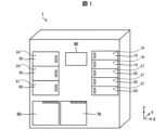
- FIG. 1 is a perspective view showing an example of the overall configuration of a co-infusion apparatus according to the present embodiment.
- FIG. 2 is a perspective view showing an example of a schematic internal configuration of the co-infusion device when the co-infusion device is viewed from the front.
- FIG. 3 is a perspective view showing an example of a schematic internal configuration of the co-infusion device when the co-infusion device is viewed from the rear.
- FIG. 4 is a block diagram showing an example of the overall configuration of a co-infusion device.
- FIG. 5 is a perspective view showing an example of the configuration of the co-infusion unit.
- FIG. 6 is a front view showing an example of a schematic configuration of the co-infusion unit.
- FIG. 1 is a perspective view showing an example of the overall configuration of a co-infusion apparatus according to the present embodiment.
- FIG. 2 is a perspective view showing an example of a schematic internal configuration of the co-infusion device when the co-infusion device is viewed from the
- FIG. 7 is a diagram for explaining adjustment of the needle tip position of the syringe.
- FIG. 8 is a diagram illustrating an example of the configuration of the second transport unit.
- FIG. 9 is a diagram for explaining the reading position of the first information.
- FIG. 10 is a perspective view showing an example of the overall configuration of a syringe shelf and a vial shelf.
- FIG. 11 is a diagram showing an example of the configuration of one syringe shelf and one vial shelf when viewed from the first transporting unit side, and a diagram for explaining the vial shelf.
- FIG. 12 is a flowchart showing an example of the flow of processing by the control unit when the control unit receives an instruction to collect a vial.
- FIG. 12 is a flowchart showing an example of the flow of processing by the control unit when the control unit receives an instruction to collect a vial.
- FIG. 13 is a perspective view showing an example of the configuration of an infusion shelf.
- FIG. 14 is a diagram showing an example of a specific configuration of the pushing portion.
- FIG. 15 is a side view showing an example of the pushing transport section.
- FIG. 16 is a perspective view showing an example of the overall configuration of the printing and inspection unit.
- FIG. 17 is a perspective view of the printing and inspection unit as seen from the rear.
- FIG. 18 is a perspective view showing an example of the internal configuration of the printing and inspection unit.
- FIG. 19 is a diagram for explaining an example of an operation from reading the first information to attaching the second label.
- FIG. 20 shows an example of an infusion bag having a first label attached to its first surface, and an example of an infusion bag having a second label attached to its second surface.
- FIG. 20 shows an example of an infusion bag having a first label attached to its first surface, and an example of an infusion bag having a second label attached to its second surface.
- FIG. 21 is a front view showing an example of an infusion receiving shelf.
- FIG. 22 is a side view showing an example of an infusion receiving shelf.
- FIG. 23 is a diagram showing an example of the shape of the rail portion.
- FIG. 24 is a diagram for explaining the shutter.
- FIG. 25 is a flowchart showing an example of a data output process.
- FIG. 26 is a diagram showing an example of a display screen in the co-injection system.
- FIG. 27 is a flowchart showing an example of the mixed injection control process.
- FIG. 28 is a diagram showing an example of a display screen in the co-injection system.
- FIG. 29 is a diagram showing an example of a display screen in the co-injection system.
- FIG. 30 is a flowchart showing an example of the display control process.
- FIG. 30 is a flowchart showing an example of the display control process.
- FIG. 31 is a diagram showing an example of a display screen in the co-injection system.
- FIG. 32 is a diagram showing an example of a display screen in the co-injection system.
- FIG. 33 is a diagram showing an example of a display screen in the co-injection system.
- FIG. 34 is a diagram showing an example of a display screen in the co-injection system.
- FIG. 35 is a diagram showing an example of a display screen in the co-injection system.
- FIG. 36 is a diagram showing an example of a display screen in the co-injection system.
- the X-axis and the Y-axis are two mutually perpendicular axes in a horizontal plane (the contact surface of the co-infusion device 1).
- the positive X-axis direction is sometimes referred to as the rightward direction, and the negative X-axis direction is sometimes referred to as the leftward direction.
- the positive Y-axis direction is sometimes referred to as the farther direction or rearward direction, and the negative Y-axis direction is sometimes referred to as the nearer direction or forward direction.
- the Z-axis is an axis that extends vertically to the XY plane, and the positive Z-axis direction is sometimes referred to as the upward direction, and the negative Z-axis direction is sometimes referred to as the downward direction.
- the co-infusion device 1 is a perspective view showing an example of the overall configuration of a co-infusion device 1.
- the co-infusion device 1 includes a syringe shelf 10, a vial shelf 20, an infusion shelf 30, a printing and inspection unit 50, an infusion receiving shelf 60, a trash can section 70, and a touch panel 80.
- the co-infusion device 1 is a device that executes a co-infusion process (co-infusion operation) of mixing a drug and an infusion using a drug, a syringe, and an infusion indicated in the preparation and administration data (hereinafter referred to as preparation data). More specifically, the co-infusion device 1 executes a co-infusion process of aspirating a drug indicated in the preparation data from a vial (a first container, an example of a drug container) containing the drug, and injecting the drug into an infusion bag (a second container, an example of an infusion container) containing the infusion.
- the infusion used in the co-infusion process may be, for example, saline (physiological saline) or a liquid containing glucose.
- the syringe, vial, infusion bag, etc. used in the co-infusion process may be collectively referred to as equipment.
- co-infusion processing include a process of aspirating a drug from a vial using a syringe and injecting it into another vial, or a process of aspirating a liquid from an infusion bag using a syringe and injecting it into a vial.
- a vial contains a solid drug
- the co-infusion device 1 uses a syringe to aspirate the liquid from the infusion bag and injects the liquid into the vial. This makes it possible to turn the solid drug in the vial into a liquid state.
- the co-infusion device 1 then uses a syringe to inject the liquid drug into the infusion bag.
- the user can load syringes, vials, and infusion bags into the co-injection device 1 by, for example, opening and closing a door.
- the air purifying section described below keeps the inside of the co-injection device 1 clean, reducing the possibility of contamination of the medicine and infusion during the co-injection process.
- the inside of the co-injection device 1 is kept at positive pressure.
- the co-injection device 1 handles medicines such as anticancer drugs, the inside of the co-injection device 1 is kept at negative pressure.
- the preparation data is data required by the control unit 140 (see FIG. 4) of the co-infusion device 1 to perform the co-infusion process and the printing process of the second label (see reference numeral 1062 in FIG. 20), and is generated based on the prescription data. Specifically, the preparation data is generated by the upper system 2 based on the prescription data, and is input from the upper system 2 to the co-infusion device 1. The preparation data may be generated by the control unit 140 of the co-infusion device 1.
- the control unit 140 of the co-infusion device 1 may convert the preparation data into working preparation data for executing the co-infusion process based on the preparation data in the co-infusion device 1 according to preset conversion conditions, and then the co-infusion process may be executed.
- the control unit 140 automatically issues the plurality of preparation data received from the upper system 2 and makes them the processing target, thereby sequentially executing the co-injection process based on each of the preparation data. Therefore, the preparation data becomes a co-injection instruction (injection instruction) for executing the co-injection process in the co-injection unit 40.
- the preparation data may be issued and the co-injection process based on the preparation data may be executed.
- the preparation data may be transmitted from the upper system 2 of the co-injection device 1 to the co-injection device 1 for each co-injection process.
- the control unit 140 requests the upper system 2 to transmit the preparation data for the co-injection unit 40 to execute the next co-injection process.
- the control unit 140 receives the preparation data, it starts the next co-injection process.
- the preparation data includes, for example, information indicating the type of drug used in the mixed injection process, the prescribed amount of the drug, information indicating the type of syringe, information indicating the type of infusion (infusion type information), and information indicating the amount of infusion drawn from the infusion bag.
- the preparation data also includes information on the number of pieces of equipment, such as vials, infusion bags, and syringes, required for the mixed injection process based on the preparation data. Note that, as another embodiment, even if the preparation data does not include information on the number of pieces of equipment, if the preparation data includes the amount of drug or infusion used to identify the information on the number of pieces of equipment, the control unit 140 may identify the number of pieces of equipment based on the amount used.
- the preparation data includes information about the infusion bag into which the medication is to be injected, as information to be printed on the second label LA12.
- This information includes prescription attribute information, prescription detail information, an order number indicating the order in which the prescription was received, and infusion type information (e.g., infusion name), etc.
- the prescription attribute information, prescription detail information, an order number indicating the order in which the prescription was received, and infusion type information, etc., are information included in the prescription data that is referenced to generate the preparation data.
- the prescription attribute information includes information indicating the name and patient ID of the patient to whom the drug has been prescribed (an example of patient identification information for identifying the patient), the name of the ward and room in which the patient is hospitalized, the name of the medical professional (an example of a person in charge) who will administer the mixed drug to the patient, the name of the department to which the medical professional belongs, etc.
- the prescription details information includes information indicating the Rp (recipe) number, infusion technique, route, drug name (an example of drug identification information indicating the type of drug), usage, dosage, administration time, comments, etc.
- Rp is information including the drug name, usage, and dosage.
- Route is information indicating the destination into the body of the liquid in the infusion bag into which the drug has been injected (e.g. peripheral vein or peripheral internal jugular).
- Administration time is information indicating the date and time when the drug in the infusion bag, which is the result of the infusion process by the infusion device 1, is administered to the patient.
- the information regarding the infusion bag into which the drug is to be injected needs to include at least the name of the drug, the patient's name, the name of the hospital room, and information indicating the date of the co-infusion.
- the date of the co-infusion is information that is recorded as the date on which the co-infusion device 1 actually performs the co-infusion process (the date on which the prescribed drug is injected into the infusion bag).
- the syringe shelf 10 is an equipment storage shelf capable of storing the syringes loaded in the co-injection device 1.
- the co-injection device 1 is provided with two upper and lower syringe shelves 10 as shown in FIG. 1.
- the syringe shelf 10 is provided with a syringe side door 16. A user can hold a syringe on the syringe shelf 10 by opening and closing the syringe side door 16.
- the types of syringes stored on each of the upper and lower syringe shelves 10 are predetermined, and in the co-injection process, a syringe stored on one of the syringe shelves 10 is used depending on the type of syringe specified by the preparation data.
- the vial shelf 20 is an equipment storage shelf capable of storing the vials filled in the co-infusion device 1.
- the co-infusion device 1 is provided with two infusion shelves 30, one above the other, as shown in FIG. 1.
- the vial shelf 20 is provided with a vial-side door 27. The user can store the vials in the vial shelf 20 by opening and closing the vial-side door 27.
- the infusion shelf 30 is an infusion storage shelf capable of storing the infusion bags filled in the co-infusion device 1.
- the infusion shelf 30 is provided with an infusion side door 34. The user can store the infusion bag on the infusion shelf 30 by opening and closing the infusion side door 34.
- the syringe side door 16, the vial side door 27, and the infusion side door 34 are doors that can block the user's access to the syringe shelf 10, the vial shelf 20, and the infusion shelf 30, respectively.
- the control unit 140 described below controls the syringe side door 16, the vial side door 27, and the infusion side door 34 so that only one of them is in an unlocked state.
- the printing and inspection unit 50 is a unit that prints the second label LA12 and affixes it to the infusion bag before or after drug injection.
- the printing and inspection unit 50 may also print an inappropriate information label (described below) and affix it to the infusion bag after drug injection.
- the printing and inspection unit 50 is also a unit that weighs the infusion bag before and after drug injection.
- the infusion receiving shelf 60 is a unit that receives infusion bags with the second label LA12 affixed thereto after drug injection.
- the infusion receiving shelf 60 is provided with an infusion receiving door 61.
- the trash can section 70 is a box that receives used syringes.
- the touch panel 80 has the functions of an operation section that receives various operations by the user, and a display section that displays various information. Note that, instead of the touch panel 80, the operation section and the display section may be provided as separate members. Also, together with or instead of the display section, a presentation section (e.g., a speaker) that presents various information may be provided.
- FIG. 2 is a perspective view showing an example of a schematic internal configuration of the co-infusion device 1 when viewed from the front (near side).
- Fig. 3 is a perspective view showing an example of a schematic internal configuration of the co-infusion device 1 when viewed from the rear (rear direction).
- the co-infusion device 1 includes the above-mentioned syringe shelf 10, vial shelf 20, infusion shelf 30, printing and inspection unit 50, infusion receiving shelf 60, and trash can section 70, as well as a co-infusion unit 40, a first transport section 110, a second transport section 120, and an air purifier section 130.
- the syringe used in the co-infusion device 1 will be referred to as syringe 501, the vial as vial 502, and the infusion bag as infusion bag 503.
- the mixing unit 40 functions as an injection section that injects medicine into the infusion bag 503 that contains the infusion liquid. When the mixing unit 40 injects medicine into the infusion bag 503, the medicine is mixed with the infusion liquid in the infusion bag 503.
- the mixing unit 40 also functions as a member that extracts the infusion liquid from the infusion bag 503.
- the mixing unit 40 can inject the infusion liquid into the vial 502 by extracting the infusion liquid from the infusion bag 503. This allows the solid medicine contained in the vial 502 to be liquidized.
- the mixing unit 40 is located between the syringe shelf 10 and the vial shelf 20 and the infusion shelf 30 and the infusion receiving shelf 60.
- the first transport unit 110 functions as a container transport unit that transports the syringe 501 indicated in the preparation data from the syringe shelf 10 to the mixing unit 40, or the vial 502 containing the drug indicated in the preparation data from the vial shelf 20 to the mixing unit 40.
- the first transport unit 110 transports the syringe 501 stored on the syringe shelf 10 and the vial 502 stored on the vial shelf 20 to the mixing unit 40.
- the first transport unit 110 grasps the upper part of the body of the syringe 501 stored on the syringe shelf 10 and delivers the syringe 501 to the mixing unit 40.
- the first transport unit 110 grasps the neck of the vial 502 stored on the vial shelf 20 and delivers the vial 502 to the mixing unit 40.
- the first transport unit 110 also transports the syringe 501 stored in the syringe shelf 10 to a cap attachment/detachment unit (not shown) before transporting the syringe 501 to the co-injection unit 40. This allows the first transport unit 110 to remove the needle cap attached to the needle of the syringe 501, and transport the syringe 501 with the needle cap removed to the co-injection unit 40.
- the first transport unit 110 also transports the syringe 501 and vial 502 after the co-injection process (the syringe 501 and vial 502 that are no longer needed) to the trash can unit 70.
- the first transport unit 110 is a transport unit that transports the syringe 501 and the vial 502 and is shared by both the syringe 501 and the vial 502, but is not limited to this.
- a transport unit dedicated to transporting the syringe 501 and a transport unit dedicated to transporting the vial 502 may be provided.
- the second transport unit 120 functions as an infusion bag transport unit that transports the infusion bag 503 indicated in the preparation data between the infusion shelf 30, the mixing unit 40, the printing and inspection unit 50, and the infusion receiving shelf 60.
- the infusion shelf 30 arranged in the upper tier stores infusion bags 503 in an arrangement of five lanes aligned in the left-right direction (X-axis direction).
- the infusion shelf 30 arranged in the lower tier stores infusion bags 503 in an arrangement of four lanes aligned in the left-right direction (X-axis direction).
- Each infusion shelf 30 can store a predetermined number of infusion bags 503 in the front-back direction (Y-axis direction) of each lane, depending on the type of infusion bag 503.
- the type of infusion bag 503 stored in each lane is predetermined, and in the co-infusion process, the infusion bag 503 stored in one of the lanes of the infusion shelf 30 is used depending on the type of infusion bag 503 specified in the preparation data.
- the second transport unit 120 transports the infusion bag 503 to the mixing unit 40.
- the second transport unit 120 transports the infusion bag 503 stored on the infusion shelf 30 to the mixing unit 40.
- the second transport unit 120 adsorbs the body of the infusion bag 503 stored on the infusion shelf 30 and hands it over to the mixing unit 40.
- the second transport unit 120 also transports the infusion bag 503 between the mixing unit 40 and the printing and inspection unit 50.
- the second transport unit 120 picks up the body of the infusion bag 503 after the drug has been injected and transports it to the printing and inspection unit 50.
- the second transport unit 120 also functions as a transfer unit that transfers the infusion bag 503 into which the drug has been injected by the mixing unit 40 to the infusion receiving shelf 60.
- the second transport unit 120 adsorbs the body of the infusion bag 503 after drug injection to which second information different from the first information has been attached by the printing/inspection unit 50 (the second label LA12, or the second label LA12 and the inappropriate information label have been affixed), and transfers it to the infusion receiving shelf 60. Details of the first information and the second information will be described later.
- the air purification unit 130 purifies and exhausts the air inside the co-injection device 1. In this embodiment, it is provided at the top of the co-injection device 1. The air purified by the air purification unit 130 flows from the top to the bottom of the co-injection device 1.
- the air purification unit 130 has, for example, a HEPA (High Efficiency Particulate Air) filter.
- each component in the co-infusion device 1 is not limited to the arrangement described above.
- the vial shelf 20 may be provided on the upper level of the syringe shelf 10.
- the syringe shelf 10 and the vial shelf 20 may be provided on the upper level of the infusion shelf 30, the infusion receiving shelf 60, and the printing and inspection unit 50.
- the syringe shelf 10, the vial shelf 20, and the infusion shelf 30 are each provided on multiple levels, but each may be provided on one level.
- the infusion receiving shelf 60 is provided on one level, but each may be provided on multiple levels.
- the printing and inspection unit 50 and the infusion receiving shelf 60 may be provided on the opposite level.
- the arrangement of each component in the co-infusion device 1 may be determined taking into consideration the convenience of the user and the ease of manufacture.
- a syringe side door 16 and/or a vial side door 27 may be provided on the side of the co-infusion device 1 (FIG. 2, right side of the page).
- one syringe 501 and one vial 502 are loaded from the front side of the co-infusion device 1.
- multiple syringes 501 or multiple vials 502 can be loaded from the side side of the co-infusion device 1.
- an infusion side door 34 may be provided on the side side of the co-infusion device 1 (FIG. 2, left side of the page).
- the co-infusion device 1 may also be configured as a co-infusion device that performs co-infusion processing using one or more robot arms, as disclosed in, for example, JP 2022-40295 A.
- Fig. 4 is a block diagram showing an example of the overall configuration of the co-infusion system 100.
- the co-infusion system 100 includes a co-infusion device 1 and a host system 2.
- the co-infusion device 1 also includes a control unit 140 and a storage unit 200. Note that Fig. 4 illustrates only the main hardware configuration that can be controlled by the control unit 140 among the hardware configurations of the co-infusion device 1.
- the control unit 140 controls the operation of the co-injection device 1 based on the preparation data, and is an example of a co-injection control device according to the present invention.
- the control unit 140 includes, for example, a syringe transport control unit 141, a vial transport control unit 142, a first transport control unit 143, a co-injection unit control unit 144, a second transport control unit 145, a pushing control unit 147, a printing/inspection unit control unit 148, and a touch panel control unit 149.
- the co-injection device 1 including the control unit 140 and the co-injection unit 40 is an example of a co-injection system according to the present invention.
- the co-injection system 100 including the co-injection device 1 and the upper system 2 may also be an example of a co-injection system according to the present invention.
- the syringe transport control unit 141 controls the operation of the components related to the transport of the syringe 501 in the syringe shelf 10.
- the vial transport control unit 142 controls the operation of the components related to the transport of the vial 502 in the vial shelf 20.
- the co-injection unit control unit 144 controls the operation of the components provided in the co-injection unit 40.
- the first transport control unit 143 controls the operation of the components included in the first transport unit 110.
- the first transport control unit 143 controls the movement of the first transport unit 110 between, for example, the syringe shelf 10, the vial shelf 20, the mixing unit 40, the wastebasket unit 70, and the cap attachment/detachment unit (not shown).
- the second transport control unit 145 controls the operation of the components included in the second transport unit 120.
- the second transport control unit 145 controls the movement of the second transport unit 120 between, for example, the infusion shelf 30, the mixing unit 40, the printing/inspection unit 50, and the infusion receiving shelf 60.
- the push-in control unit 147 controls the operation of the components related to the transportation of the infusion bag 503 in the infusion shelf 30.
- the printing and inspection unit control unit 148 controls the operation of the components provided in the printing and inspection unit 50.
- the touch panel control unit 149 controls the touch panel 80.
- the storage unit 200 also stores data for the control unit 140 to perform the co-injection process and the printing process.
- the storage unit 200 stores, for example, preparation data.
- FIG. 5 is a perspective view showing an example of the configuration of the co-infusion unit 40.
- Fig. 6 is a front view showing an example of the schematic configuration of the co-infusion unit 40, and is a diagram for explaining an example of the operation of the co-infusion unit 40.
- Fig. 7 is a diagram for explaining adjustment of the needle tip position of the syringe 501.
- the mixing unit 40 includes a syringe holder 41, a vial holder 42, an infusion bag holder 43, a stopper position detector 45, and a first detector 46.
- the syringe holding section 41 is a member that holds the syringe 501 (the syringe 501 transported by the first transport section 110) for injecting a medicine into the infusion bag 503.
- the syringe 501 includes a syringe 5011, a needle 5014, and a plunger 5015.
- the plunger 5015 is a pusher that moves in and out of the syringe 5011.
- the plunger 5015 moves in and out of the syringe 5011 to draw medicine or the like into the syringe 5011 or to expel medicine or the like from the syringe 5011.
- the syringe 5011 includes a needle-side end 5012 to which the needle 5014 is attached, and a flange 5013 that is the end opposite the needle-side end 5012 and is the end on the side where the plunger 5015 moves in and out.
- the syringe holding portion 41 includes a needle clamping portion 411, a position fixing portion 412, a first syringe holding portion 416, and a plunger clamping portion 417.
- the member described as holding the object is merely an example, and the member may be any member capable of holding the object.
- the needle clamping portion 411 is a member that clamps the needle 5014.
- the needle clamping portion 411 clamps the needle 5014 and positions the tip of the needle 5014 at a fixed position. This allows the needle 5014 to be punctured at the desired position (correct position) of the stopper provided on the infusion bag 503 even if it is bent during the mixed injection process.
- the first syringe holding section 416 is a member that initially holds the syringe 501 that the first transport section 110 transports from the syringe shelf 10.
- the first syringe holding section 416 clamps the side of the syringe 5011 (e.g., the lower part of the syringe 5011) inserted into the first syringe holding section 416.
- the position fixing portion 412 is a member that fixes the position of the syringe 501 in the extension direction of the syringe 501 at the needle side end portion 5012 and the flange 5013.
- the relative positions of the second syringe holding portion 413 and the third syringe holding portion 414 that constitute the position fixing portion 412 can be changed along the extension direction of the syringe 501.
- the second syringe holding portion 413 and the third syringe holding portion 414 are attached so that at least one of the second syringe holding portion 413 and the third syringe holding portion 414 can move along the extension direction of the syringe 501.
- the second syringe holding part 413 abuts from the underside of the needle side end part 5012, and the third syringe holding part 414 abuts from the upper side of the flange 5013.
- the position fixing part 412 can fix the syringe 5011 so that it does not slip in the extension direction of the syringe 501 with a smaller force than when clamping only the side of the syringe 5011.
- smooth operation of the plunger 5015 is possible. This improves the accuracy of adjusting the amount of suction and injection of the syringe 501.
- the plunger clamping portion 417 is a member that clamps the plunger 5015.
- the plunger clamping portion 417 clamps the tip of the plunger 5015.
- the plunger clamping portion 417 moves in the vertical direction relative to the needle clamping portion 411, the position fixing portion 412, and the first syringe holding portion 416, thereby moving the plunger 5015 relative to the syringe 5011.
- the vial holder 42 is a member that holds the vial 502 (the vial 502 transported by the first transport unit 110) that contains the medicine to be injected into the infusion bag 503. In this embodiment, the vial holder 42 clamps the neck of the vial 502.
- the infusion bag holding section 43 is a member that holds the infusion bag 503 (the infusion bag 503 transported by the second transport section 120).
- the infusion bag holding section 43 includes an infusion clamping section 431 that clamps the neck of the infusion bag 503, and a mounting table 432 on which the infusion bag 503 is placed when infusion is extracted from the infusion bag 503 or injected into the infusion bag 503.
- the mixing unit 40 is provided on the side wall of the infusion shelf 30. Specifically, in the mixing device 1, the mixing unit 40 is arranged so that the syringe holding section 41, the vial holding section 42, and the infusion bag holding section 43 face toward the syringe shelf 10 and the vial shelf 20 (positive X-axis direction).
- the syringe holding part 41 can move in the vertical direction ( ⁇ Z-axis direction). This allows the needle 5014 to puncture the vial 502 or infusion bag 503 located directly below the syringe 501 held by the syringe holding part 41.
- the vial holding part 42 and the infusion bag holding part 43 are movable in the front-rear direction ( ⁇ Y-axis direction) of the co-infusion device 1.
- the vial holding part 42 and the infusion bag holding part 43 are attached to the base 44, and the base 44 moves in the front-rear direction of the co-infusion device 1.
- the base 44 functions as a moving part that moves the vial holding part 42 and the infusion bag holding part 43 in a direction ( ⁇ Y-axis direction) perpendicular to the extension direction ( ⁇ Z-axis direction) of the needle 5014 of the syringe 501 held by the syringe holding part 41.
- the direction perpendicular to the extension direction of the needle 5014 is sometimes simply referred to as the direction perpendicular to the needle 5014.
- the vial holding portion 42 and the infusion bag holding portion 43 can move between the position indicated by reference numeral 1001 in FIG. 6 and the position indicated by reference numeral 1002 in FIG. 6.
- the position indicated by reference numeral 1001 in FIG. 6 is the first puncture position when the needle 5014 punctures the vial 502, and the position indicated by reference numeral 1002 in FIG. 6 is the second puncture position when the needle 5014 punctures the infusion bag 503. Therefore, the vial 502 held in the vial holding portion 42, or the infusion bag 503 held in the infusion bag holding portion 43 can be positioned at the puncture position of the needle 5014 of the syringe 501 held in the syringe holding portion 41.
- the base 44 is an example of the moving part, and the moving part is not limited to the base 44, but may be any member that moves the vial holding part 42 and the infusion bag holding part 43 in a direction perpendicular to the needle 5014.
- the moving part may also move the syringe holding part 41 relative to the vial holding part 42 and the infusion bag holding part 43 in a direction perpendicular to the needle 5014.
- the moving part may be capable of moving the vial holding part 42 and the infusion bag holding part 43 relative to the syringe holding part 41.
- the mixing unit 40 is rotatable around a rotation axis Ax (Ax is the rotation axis).
- the rotation axis Ax is an axis that extends perpendicularly ( ⁇ X-axis direction) to the base on which the syringe holder 41, the vial holder 42, and the infusion bag holder 43 are provided.
- the mixing unit 40 rotates about the rotation axis Ax, thereby moving the vial 502 above the syringe 501.
- the mixing unit 40 rotates about the rotation axis Ax, thereby moving the infusion bag 503 above the syringe 501.
- the mixing unit 40 moves the plunger 5015 downward, thereby moving the drug contained in the vial 502 or the infusion contained in the infusion bag 503 to the syringe 5011.
- the infusion liquid contained in the syringe 5011 is injected into the vial 502 in the state shown by reference numeral 1001 in FIG. 6 (where the vial 502 is located directly below the syringe 501).
- the medicine contained in the syringe 5011 is injected into the infusion bag 503 in the state shown by reference numeral 1002 in FIG. 6 (where the infusion bag 503 is located directly below the syringe 501).
- the infusion bag 503 has a first surface SF1 and a second surface SF2.
- the first surface SF1 and the second surface SF2 are opposite surfaces of the infusion bag 503 and are the main surfaces of the infusion bag 503.
- the main surface of the infusion bag 503 refers to the surface with the largest area among the multiple surfaces that make up the infusion bag 503.
- the infusion bag 503 is stored so that the first surface SF1 and the second surface SF2 of the infusion bag 503 face a predetermined direction.
- the infusion bag 503 is held on the rail section 36 of the infusion shelf 30 so that the first surface SF1 faces the back of the mixing device 1 and the second surface SF2 faces the front of the mixing device 1.
- the second transport section 120 sucks the first surface SF1 on the infusion shelf 30 to hold the infusion bag 503, and transports and hands over the infusion bag 503 to the infusion bag holding section 43 without changing its orientation.
- the mixing unit 40 rotates around the rotation axis Ax.
- the infusion bag 503 is placed on the placement table 432 with the second surface SF2 abutting against the placement table 432.
- the mounting table 432 rotates in the horizontal plane (XY plane) around the rotation axis Ax that is perpendicular to the above-mentioned predetermined direction ( ⁇ Y axis direction). Therefore, as described above, the infusion bag 503 can be placed on the mounting table 432 without changing the orientation of the infusion bag 503 transported from the infusion shelf 30. Therefore, in order to place the infusion bag 503 on the mounting table 432, there is no need to provide the co-infusion device 1 with a mechanism for changing the orientation of the infusion bag 503.
- the surface of the mounting base 432 is approximately parallel to the X-axis direction. Therefore, by rotating the mixing unit 40 around the rotation axis Ax and adjusting the rotational position of the mixing unit 40, the surface of the mounting base 432 can be oriented in a predetermined direction in which the first surface SF1 and the second surface SF2 of the infusion bag 503 are oriented, without changing the orientation of the infusion bag 503.
- By orienting the surface of the mounting base 432 and the first surface SF1 and the second surface SF2 of the infusion bag 503 in the same direction it is possible to prevent the shape of the infusion bag 503 from being distorted when the infusion bag 503 is brought into contact with the mounting base 432. It is also possible to prevent the position of the part of the infusion bag 503 containing the liquid (e.g., the body of the infusion bag 503) from moving when the infusion bag 503 is brought into contact with the mounting base 432.
- the stopper position detection unit 45 is a sensor that detects the position of the rubber stopper 5021 of the vial 502 held in the vial holding unit 42.
- the rubber stopper 5021 is provided on the upper surface of the vial 502 and is a member that is punctured by the needle 5014.
- the stopper position detection unit 45 is disposed in a position that is directly above the vial holding unit 42 at the second puncture position indicated by reference numeral 1002 in FIG. 6.
- the stopper position detection unit 45 may be, for example, a distance measurement sensor.
- the first detection unit 46 detects the tip of the needle 5014 of the syringe 501 held by the syringe holding unit 41.
- the syringe holding unit 41 moves downward when the needle 5014 punctures the vial 502 held by the vial holding unit 42 or the infusion bag 503 held by the infusion bag holding unit 43.
- the first detection unit 46 detects the tip of the needle 5014 that moves with this downward movement.
- the first detection unit 46 may be, for example, an optical sensor equipped with a light receiving unit that receives light reflected by the needle 5014.
- Reference distance information indicating the distance in the vertical direction between the position where the stopper position detection unit 45 detects the target and the position where the first detection unit 46 detects the target is stored in advance in the storage unit 200.
- the co-injection unit control unit 144 can calculate the distance from the position of the needle 5014 that passed in front of the first detection unit 46 to the rubber stopper 5021 from the difference between the distance from the stopper position detection unit 45 to the rubber stopper 5021 detected by the stopper position detection unit 45 and the distance indicated by the reference distance information.
- the vial holding part 42 moves in a direction perpendicular to the needle 5014 ( ⁇ Y-axis direction). Therefore, the position of the vial 502 in the up-down direction is approximately the same at the first puncture position indicated by reference number 1001 in FIG. 6 and the second puncture position indicated by reference number 1002 in FIG. 6. Therefore, the position of the rubber stopper 5021 detected by the stopper position detection part 45 at the second puncture position can also be applied to the first puncture position. Therefore, the co-infusion unit control part 144 can puncture the rubber stopper 5021 with only the tip of the needle 5014 by moving the needle 5014 that has passed in front of the first detection part 46 downward by the calculated distance.
- the co-injection unit 40 may include a second detection unit 47.
- the second detection unit 47 is a sensor that detects the syringe holding unit 41 directly above the first detection unit 46.
- the second detection unit 47 may be an optical sensor, similar to the first detection unit 46.
- the syringe holding part 41 is moved downward at a predetermined speed V.
- the co-injection unit control part 144 measures a first detection time T1 from when the second detection part 47 detects the syringe holding part 41 to when the first detection part 46 detects the needle of the jig 601.
- the tip position of the needle of the jig 601 when the second detection part 47 detects the syringe holding part 41 is measured by a person or the like and stored in advance in the memory part 200.
- the position that serves as the measurement reference for the tip position can be set arbitrarily.
- the syringe holding part 41 is moved downward at a predetermined speed V.
- the mixing unit control part 144 measures the second detection time T2 from when the second detection part 47 detects the syringe holding part 41 to when the first detection part 46 detects the needle 5014.
- the mixing unit control part 144 can determine the tip position of the needle 5014 of the syringe 501 actually used in the mixing process when the second detection part 47 detects the syringe holding part 41 holding the syringe 501 actually used in the mixing process, from (second detection time T2-first detection time T1) x predetermined speed V and the tip position of the needle of the jig 601 stored in advance in the memory part 200.
- [Specific configuration of the second conveying unit] 8 is a diagram showing an example of the configuration of the second transport unit 120.
- the second transport unit 120 is a member that removes an infusion bag 503 from the infusion shelf 30 in order to inject a drug into the infusion bag 503 indicated in the preparation data, for example.
- the second transport unit 120 includes an adsorption unit 121 and a third reading unit 122 (reading unit).
- the suction part 121 is a member that suctions the body part 5031 of the infusion bag 503.
- the suction part 121 is an example of a holding member that holds the infusion bag 503, and as long as the second transport unit 120 can hold the infusion bag 503, the holding member does not have to be the suction part 121.
- the second transport control unit 145 detaches the infusion bag 503 by controlling the air pressure in the suction part 121.
- three suction parts 121 are provided along the vertical direction at positions facing the infusion bag 503 in the second transport section 120.
- the three suction parts 121 include a main suction part 121A and two sub suction parts 121B.
- the main suction part 121A is always used to adsorb the infusion bag 503 when the second transport part 120 holds the infusion bag 503.
- the main suction part 121A is provided in a position that allows it to face all of the infusion bags 503 of different sizes that can be stored in the co-infusion device 1.
- the two sub-suction parts 121B adsorb the infusion bag 503 together with the main suction part 121A depending on the vertical size of the infusion bag 503. Therefore, at least one of the two sub-suction parts 121B may not adsorb the infusion bag 503 depending on the size of the infusion bag 503.
- the positional relationship between the adsorption location of the infusion bag 503 (e.g., the infusion shelf 30 and the mixing unit 40) and the second transport unit 120 is determined in advance so that the main adsorption unit 121A is always used.
- the control unit 140 stores in a volatile memory the type of the infusion bag 503 being transported by the second transport unit 120. Therefore, if the power supply of the co-infusion device 1 is turned off due to a power outage or the like while the second transport unit 120 is transporting the infusion bag 503, the control unit 140 may not be able to manage the type of the infusion bag 503 held by the second transport unit 120. In such a case, in the co-infusion device 1 after the power supply is turned on, the printing and inspection unit 50 affixes a label on which information indicating that the co-infusion process using the infusion bag 503 may not have been performed correctly is printed to the infusion bag 503 held by the second transport unit 120.
- the information may be an example of second information different from the first information (described later).
- the label is a label indicating the second information, and may be affixed in a position that does not overlap with the first label LA11 (see reference numeral 1061 in FIG. 20) like the second label LA12.
- the label is affixed to area Ar11 on the second surface SF2 facing the main suction part 121A.
- the positional relationship between the main suction part 121A and the guide part 56 (described later) of the printing/inspection unit 50 is determined in advance so that the label can be affixed to area Ar11.
- the part of the second surface SF2 opposite the part that is adsorbed by the suction part 121 is less likely to move, allowing the label to be affixed more reliably.
- Area Ar11 is opposite the part that is adsorbed on any infusion bag 503. Therefore, by using area Ar11 as the label affixing position, the label can be affixed more reliably no matter what infusion bag 503 is held by the second transport part 120.
- the label may be attached by the user. At least a part of the label may be attached to the area Ar11.
- the number of suction parts 121 is not limited to three, and may be one or a number other than three. When multiple suction parts 121 are provided, at least one of them should be the main suction part 121A.
- the third reading unit 122 reads the first information contained in the first label LA11 (see reference numeral 1061 in FIG. 20) affixed to the body 5031 of the infusion bag 503.
- the first label LA11 is a label that is affixed in advance to the infusion bag 503 by the pharmaceutical manufacturer that provides the infusion bag 503, and is also referred to as an infusion label.
- the first information read by the third reading unit 122 is, for example, infusion type information that indicates the type of infusion.
- the third reading unit 122 includes a light receiving unit 1222 that receives light reflected on the surface of the infusion bag 503.
- the third reading unit 122 includes a light emitting unit 1221 that emits light toward the surface of the infusion bag 503 stored in the infusion shelf 30, the light receiving unit 1222 may receive the light emitted by the light emitting unit 1221 that is reflected on the surface of the infusion bag 503.
- the third reading unit 122 reads the first information based on a change in the amount of light received by the light receiving unit 1222. If the first information is included in a barcode, the third reading unit 122 may be realized by a barcode reader.
- the third reading unit 122 functions as a recognition unit that recognizes the orientation of the first surface SF1 of the infusion bag 503. Specifically, the third reading unit 122 recognizes the orientation of the first surface SF1 based on a change in the amount of light received by the light receiving unit 1222. In this case, the third reading unit 122 can recognize the orientation of the first surface SF1 by functioning as an optical member. In this embodiment, when the third reading unit 122 can read the first information, the control unit 140 recognizes that the orientation of the first surface SF1 is a predetermined direction. In this embodiment, the predetermined direction is the rear direction of the co-infusion device 1 (the direction in which the third reading unit 122 is located when viewed from the infusion shelf 30).
- the third reading unit 122 reads the first information contained in the first label LA11 from the infusion bag 503 stored on the infusion shelf 30.
- the first label LA11 is affixed to the first surface SF1. Therefore, when the second transport unit 120 removes the infusion bag 503 from the infusion shelf 30, if the infusion bag 503 is stored on the infusion shelf 30 such that the second transport unit 120 and the first label LA11 face each other, the third reading unit 122 can recognize that the orientation of the first surface SF1 is toward the back of the co-infusion device 1.
- the control unit 140 determines whether the type of infusion indicated by the first information is the same as the type of infusion indicated in the preparation data, as a result of the third reading unit 122 reading the first information. If the control unit 140 determines that the two types are the same, it transports the infusion bag 503 to the mixing unit 40 or the like, without reporting an error indicating that they are not the same. On the other hand, if the control unit 140 determines that the two types are not the same, it may report an error, or may place the infusion bag 503 on the infusion receiving shelf 60 and remove another infusion bag 503 from the infusion shelf 30.
- Fig. 10 is a perspective view showing an example of the overall configuration of the syringe shelf 10 and the vial shelf 20.
- Reference numeral 1025 in Fig. 11 is a diagram showing an example of the configuration of one syringe shelf 10 and one vial shelf 20 when viewed from the first transport unit 110 side.
- Reference numeral 1026 in Fig. 11 is a diagram for explaining the vial shelf 20.
- the syringe shelf 10 includes a plurality of equipment holding sections 11, an equipment transport section 12, an object detection section 13, and a syringe detection section 14. Note that an equipment holding section 11 is also attached to the attachment section 1211 of the equipment transport section 12 shown in FIG. 10, but is not shown in the figure.
- the user Prior to the mixed injection process, the user loads the syringe 501 into the syringe shelf 10.
- the syringe 501 is loaded into the syringe shelf 10 with the needle cap 5016 attached to the needle 5014.
- a plurality of holes 172 are formed in the plate-like member 171 that defines each syringe shelf 10. This allows, for example, air purified by the air purification unit 130 (see FIG. 2) to flow efficiently from the top to the bottom of the co-infusion device 1.
- the multiple equipment holding parts 11 are members capable of holding syringes 501.
- one equipment holding part 11 holds one syringe 501, but one equipment holding part 11 may hold multiple syringes 501.
- the equipment holding part 11 includes a free roller 1111 and an equipment clamping part 1112.
- the equipment clamping portion 1112 clamps the syringe 501.
- the equipment clamping portion 1112 clamps the flange 5013 of the syringe 501.
- the equipment clamping portion 1112 is provided at a height such that the syringe 501 does not touch the plate-like member 171 when the syringe 501 is held by the equipment holding portion 11.
- the pair of equipment clamping parts 1112 are biased in a direction approaching each other so that they can clamp the syringe 501.
- the equipment clamping parts 1112 are spaced apart to a degree smaller than the width of the flange 5013 when they are not clamping the flange 5013.
- the equipment clamping parts 1112 move in accordance with the shape of the flange 5013. This allows the equipment clamping parts 1112 to clamp the syringe 501.
- a free roller 1111 that has a rotation axis extending in the vertical direction and can rotate on the XY plane is provided below the tip of the equipment clamping part 1112.
- the free roller 1111 holds the vicinity of the flange 5013 of the syringe 5011 clamped by the equipment clamping part 1112.
- the equipment transport unit 12 is a member that transports at least one of the multiple equipment holding units 11 to the working area Ar1.
- the equipment transport unit 12 is an endless rotating member (rotating belt) to which the multiple equipment holding units 11 are connected. Therefore, in this embodiment, the equipment transport unit 12 transports the equipment holding units 11 one by one to the working area Ar1.
- the equipment transport unit 12 may also be a transport unit that transports multiple equipment holding units 11 to the working area Ar1 at once.
- the working area Ar1 is an area where the user causes at least one of the multiple equipment holding parts 11 to hold the syringe 501.
- the working area Ar1 is also an area where the user removes the syringe 501 held by at least one of the multiple equipment holding parts 11.
- the working area Ar1 is an area where the user causes one equipment holding part 11 to hold the syringe 501, and where the user removes the syringe 501 held by one equipment holding part 11.
- the working area Ar1 may function only as an area where the user causes at least one of the multiple equipment holding parts 11 to hold the syringe 501. In this case, the area where the user removes the syringe 501 held in the equipment holding part 11 may be provided in a position separate from the working area Ar1.
- the working area Ar1 may function only as an area where the user removes the syringe 501 held in the equipment holding part 11. In this case, the area where the user causes the syringe 501 to be held in the equipment holding part 11 may be provided in a position separate from the working area Ar1.
- the equipment transport unit 12 transports another equipment holding unit 11 in place of the equipment holding unit 11 located in the working area Ar1 when the object detection unit 13 detects an object (e.g., the user's hand) and then stops detecting the object, triggering the transport unit 12 to transport another equipment holding unit 11 instead of the equipment holding unit 11 located in the working area Ar1.
- the user's hand is inserted into the working area Ar1, the user causes the equipment holding unit 11 to hold the syringe 501, and then when the user's hand leaves the working area Ar1, the equipment transport unit 12 transports another equipment holding unit 11 to the working area Ar1.
- the equipment transport unit 12 may transport another equipment holding unit 11 to the working area Ar1 when the syringe detection unit 14 detects the syringe 501 held by the equipment holding unit 11 or when the syringe detection unit 14 can no longer detect the syringe 501 held by the equipment holding unit 11.
- the equipment transport unit 12 may transport another equipment holding unit 11 instead of the equipment holding unit 11 located in the working area Ar1 in response to a transport instruction from the user.
- the syringe transport control unit 141 may receive the transport instruction from the user via, for example, the touch panel 80.
- the equipment transport unit 12 changes the equipment holding unit 11 located in the working area Ar1, for example by rotating counterclockwise. This transport operation makes it possible to transport to the working area Ar1 another equipment holding unit 11 not holding a syringe 501, in place of the equipment holding unit 11 holding the syringe 501 in the working area Ar1.
- the object detection unit 13 is a member that detects an object inserted into the working area Ar1. In this embodiment, the object detection unit 13 detects the user's hand or arm inserted in the working area Ar1.
- the syringe detection unit 14 is a member that detects the syringe 501 held in the equipment holding unit 11 located in the working area Ar1. In this embodiment, the syringe detection unit 14 detects the syringe 5011 when the syringe 501 is held in the equipment holding unit 11.
- the storage unit 200 stores syringe inventory information indicating the type and number of syringes 501 stored in the syringe shelf 10.
- the syringe inventory information stores information identifying each equipment holding unit 11, information indicating the type of syringe 501 held in each equipment holding unit 11, and information indicating the transport position of each equipment holding unit 11 in association with each other.
- the control unit 140 then updates the syringe inventory information as appropriate in response to the loading of syringes 501 into the equipment holding units 11 of the syringe shelf 10 and the removal of syringes 501 from the equipment holding units 11.
- the vial shelf 20 comprises a plurality of instrument holders 21, an instrument transport section 22, an object detector 23, and a vial detector 24. Also, as indicated by reference numeral 1025 in Figure 11, the vial shelf 20 comprises a first reader 25 (reader) and a roller driver 26. Note that an instrument holder 21 is also attached to the mounting section 221 of the instrument transport section 22 shown in Figure 10, but is not shown in the figure.
- the vial shelf 20 Prior to the co-injection process, the vial shelf 20 is filled with vials 502 by the user.
- the vials 502 are provided with rubber stoppers 5021 (see FIG. 5) that close the openings and lids that are placed on the rubber stoppers 5021.
- the vials 502 are loaded into the vial shelf 20 with the lids removed.
- a plurality of holes 172 are formed in the plate-like member 171 that defines each vial shelf 20.
- the equipment holding part 21 is a member capable of holding a vial 502. In this embodiment, one equipment holding part 21 holds one vial 502, but one equipment holding part 21 may hold multiple vials 502.
- the pair of equipment clamping parts 212 are biased in a direction approaching each other so that they can clamp the vial 502.
- the equipment clamping parts 212 are spaced apart to a degree smaller than the width of the neck of the vial 502 when the neck is not being clamped.
- the equipment clamping parts 212 move in accordance with the shape of the neck. This allows the equipment clamping parts 212 to clamp the vial 502.
- a free roller 211 is provided at the tip of the equipment clamping section 212, which has a rotation axis extending in the vertical direction and is rotatable on the XY plane.
- the free roller 211 holds the vial 502 by supporting the neck of the vial 502 at three points together with the drive roller 213, which is provided on the side where the equipment clamping section 212 is supported and in a position opposite the center of the free roller 211.
- the drive roller 213 rotates while holding the vial 502
- the vial 502 also rotates.
- the free roller 211 also rotates.
- a first magnet gear 214 is provided on the upper part of the drive roller 213.
- the drive roller 213 and the first magnet gear 214 are connected to a common rotation axis that extends in the vertical direction, and can rotate on the XY plane.
- the drive roller 213 rotates in conjunction with the rotation of the second magnet gear 261 provided in the roller drive unit 26, the drive roller 213 also rotates.
- the equipment transport unit 22 is a member that transports at least one of the multiple equipment holding units 21 to the working area Ar2.
- the equipment transport unit 22 is an endless rotating member to which the multiple equipment holding units 21 are connected. Therefore, in this embodiment, the equipment transport unit 22 transports the equipment holding units 21 one by one to the working area Ar2.
- the equipment transport unit 22 may also be a transport unit that transports multiple equipment holding units 21 to the working area Ar2 at one time.
- Working area Ar2 is an area where the user causes at least one of the multiple equipment holding units 21 to hold the vial 502.
- Working area Ar2 is also an area where the user removes the vial 502 held in at least one of the multiple equipment holding units 21.
- Working area Ar2, like working area Ar1 may also be an area that functions only as an area for holding the vial 502, or an area that functions only as an area for removing the vial 502.
- the equipment transport unit 22 has the same function as the equipment transport unit 12. Specifically, the equipment transport unit 22 transports another equipment holding unit 21 in place of the equipment holding unit 21 located in the working area Ar2 when the object detection unit 23 detects an object (e.g., the user's hand) and then stops detecting the object, which is a trigger for the object transport unit 22. In addition to detecting the user's movement, the equipment transport unit 12 may transport another equipment holding unit 11 to the working area Ar2 when the vial detection unit 24 detects the vial 502 held in the equipment holding unit 21 or when the vial detection unit 24 can no longer detect the vial 502 held in the equipment holding unit 21. The equipment transport unit 12 changes the equipment holding unit 21 located in the working area Ar2 by, for example, rotating counterclockwise.
- the vial transport control unit 142 may transport another equipment holding unit 21 instead of the equipment holding unit 21 located in the working area Ar2, for example, in response to a transport instruction from the user.
- the object detection unit 23 is a member that detects an object inserted into the working area Ar2.
- the object detection unit 23 detects the user's hand or arm inserted into the working area Ar2.
- the vial detection unit 24 detects the vial 502 held by the equipment holding unit 21 located in the working area Ar2.
- the first reading unit 25 is a member that reads drug identification information indicating the type of drug contained in the vial 502, which is displayed on the surface of the vial 502, in a portion of the transport path along which the equipment transport unit 22 transports the multiple equipment holding units 21.
- the vial 502 is provided with a barcode on which the drug identification information is recorded, and the first reading unit 25 according to this embodiment is a barcode reader.
- the first reading unit 25 is disposed in a position where it can read the barcode from the vial 502 transported to the removal position PO11.
- the removal position PO11 is the position where the first transport unit 110 removes the vial 502.
- the roller drive unit 26 is a motor that rotates the second magnet gear 261 attached to the roller drive unit 26 in order to rotate the drive roller 213 of the instrument holder 21.
- the rotation axis of the roller drive unit 26 extends in the Y-axis direction, and the second magnet gear 261 is attached to the rotation axis.
- the vial transport control unit 142 drives the roller drive unit 26
- the second magnet gear 261 also rotates.
- the first magnet gear 214 rotates in conjunction with the rotation of the second magnet gear 261.
- the drive roller 213 connected to the same rotation axis as the first magnet gear 214 rotates in conjunction with the rotation of the first magnet gear 214, and the vial 502 abutting against the drive roller 213 rotates.
- the first reading unit 25 can read the barcode no matter where the barcode is attached on the surface of the vial 502.
- the vial transport control section 142 controls the instrument transport section 22 to transport the instrument holders 21 holding the vials 502 to be removed sequentially to the removal position PO11.
- the memory unit 200 stores drug inventory information that corresponds to, for example, information identifying each equipment holding unit 21, information indicating the type of drug contained in the vial 502 held in each equipment holding unit 21, and information indicating the transport position of each equipment holding unit 21.
- the control unit 140 then updates the drug inventory information as appropriate in response to the loading of vials 502 into the equipment holding units 21 of the vial shelf 20 and the removal of vials 502 from the equipment holding units 21.
- the vial transport control unit 142 when the vial transport control unit 142 receives the issuance of preparation data after the first transport unit 110 removes the vial 502 from the equipment holding unit 21, the vial transport control unit 142 transports the equipment holding unit 21 holding the vial 502 to be used in the next mixed injection process to the removal position PO11.
- the vial transport control unit 142 may transport the equipment holding unit 21 holding a vial 502 containing the same type of drug as the vial 502 to the removal position PO11 even if the first transport unit 110 does not receive the issuance of preparation data after removing the vial 502.
- the vial transport control unit 142 refers to the drug inventory information in the memory unit 200 to determine whether an equipment holding unit 21 exists that holds a vial 502 that contains the same type of drug as the vial 502 that the first transport unit 110 is removing. If the vial transport control unit 142 determines that an equipment holding unit 21 exists that holds the vial 502, it transports the equipment holding unit 21 to the removal position PO11 regardless of whether or not the issuance of preparation data has been accepted.
- the first transport control unit 143 when the first transport control unit 143 receives the issuance of preparation data, it can remove the vial 502 from the removal position PO11 without waiting for the vial 502 to be transported to the removal position PO11. Therefore, the control unit 140 can quickly start the mixing process based on the preparation data that will be sent to the mixing device 1 in the future, making it possible to shorten the overall time required for the mixing process.
- the mixing device 1 may perform such processing when it is permitted to reuse the syringe 501 and perform successive mixing processes using the same type of drug in order to conserve the number of syringes 501 used.
- [Vial recovery process] 12 is a flowchart showing an example of the flow of processing by the control unit 140 when the control unit 140 receives an instruction to collect the vial 502. Note that the collection process described here may be executed to collect other equipment such as the syringe 501 or the infusion bag 503.
- the equipment transport unit 22 may transport the equipment holding unit 21, which holds the vial 502 designated for collection, to the working area Ar2. This allows the user to easily collect the vial 502 stored in the vial shelf 20.
- each of the multiple vial shelves 20 enters the recovery mode for recovering the vials 502 held in the equipment holding section 21 is preset.
- Information indicating the order is stored in the memory section 200 in association with each vial shelf 20.
- Information regarding which vials 502 are designated as recovery targets is also stored in the memory section 200.
- the control unit 140 designates the vial 502 as a target for collection.
- the equipment transport unit 22 receives the above-mentioned collection instruction, it transports the equipment holding unit 21, which holds the vial 502 whose drug identification information could not be read, to the working area Ar2.
- the co-injection device 1 cannot use the drug contained in the vial 502 whose drug identification information cannot be read, for the co-injection process. Therefore, by transporting the vial 502 based on the above-mentioned designation, the user can collect the vial 502 that cannot be used in the co-injection process.
- the control unit 140 also designates, for example, the vial 502 designated by the user via the touch panel 80 as the one to be collected.
- the equipment transport unit 22 receives the above-mentioned collection instruction, it transports the equipment holding unit 21 holding the vial 502 designated by the user to the working area Ar2.
- the user can collect the vial 502 designated by the user.
- the above-mentioned collection instruction may include information on the vial 502 designated by the user as the one to be collected.
- the vial transport control unit 142 determines whether the above-mentioned collection instruction has been received, for example, via the touch panel 80 (S11). The vial transport control unit 142 waits for the receipt of the above-mentioned collection instruction until it is received (if NO in S11).
- the vial transport control unit 142 determines that the above recovery instruction has been received (YES in S11), it refers to the memory unit 200 to select the vial shelf 20 for which the smallest order in the above recovery mode has been set (S12). The vial transport control unit 142 determines whether the status of the selected vial shelf 20 indicates that the first transport unit 110 (removal unit) is removing a vial 502 (removing vial 502) (S13).
- the above status is managed for each vial shelf 20 in the memory unit 200.
- the control unit 140 sets the status of that vial shelf 20 to "removing the vial 502".
- the control unit 140 determines that the first transport unit 110 has removed the vial 502 from the vial shelf 20, it sets the status of that vial shelf 20 to "not removing the vial 502".
- the control unit 140 determines that the first transport unit 110 is holding the vial 502 and has moved a certain distance from the vial shelf 20, it sets the status of that vial shelf 20 to "not removing the vial 502".
- the vial transport control unit 142 determines that the status of the vial shelf 20 does not indicate that the vial 502 is being removed (NO in S13), it sets the selected vial shelf 20 to recovery mode. Then, the vial transport control unit 142 determines whether the vial 502 to be recovered is present on the selected vial shelf 20 by referring to the memory unit 200 (S14).
- the vial transport control unit 142 determines that the vial 502 to be collected is present on the selected vial shelf 20 (YES in S14), it controls the equipment transport unit 22 to transport the vial 502 to be collected from the vial shelf 20 to the working area Ar2. At this time, the vial transport control unit 142 determines whether the vial 502 to be collected is held in each of the multiple equipment holding units 21. When the vial transport control unit 142 determines that the vial 502 to be collected is held, it controls the equipment transport unit 22 to preferentially transport the equipment holding unit 21 that holds the vial 502 that is held earlier in the equipment holding unit 21 to the working area Ar2 (S15). Note that the memory unit 200 stores information indicating the holding order of the vials 502 in association with the position of the equipment holding unit 21.
- the control unit 140 designates the number of vials 502 specified by the user as the vials 502 to be collected, giving priority to the vials 502 that are earliest in the storage order (earliest in the order of filling into the vial shelf 20).
- the vial transport control unit 142 controls the instrument transport unit 22 to transport the above number of vials 502 to the working area Ar2. This allows the user to collect the desired number of vials 502, giving priority to the vials 502 that are earliest in the storage order.
- the vial transport control unit 142 may receive a selection operation via the touch panel 80 as to whether to collect from the vial 502 with the later or earlier holding order, and may execute control to collect from the vial 502 with the later or earlier holding order in accordance with the selection operation.
- the vial transport control unit 142 determines whether the equipment transport unit 22 has transported all of the vials 502 to be collected to the working area Ar2 in the selected vial shelf 20 (S16). If the vial transport control unit 142 determines that the transport of all of the vials 502 to be collected has not been completed (NO in S16), it executes the process of S15. Note that in steps S15 to S16, if the vial 502 transported to the working area Ar2 cannot be detected by the vial detection unit 24, the vial transport control unit 142 determines that the collection of the vial 502 has been completed, and repeats the process of transporting the next vial 502 to be collected to the working area Ar2. This allows the user to collect all of the vials 502 to be collected.
- the vial transport control unit 142 determines whether there is another vial shelf 20 that can be selected (S17). If the collection mode order set for the vial shelf 20 selected in S12 is not the last order, the vial transport control unit 142 determines that there are further vial shelves 20 that can be selected.
- the vial transport control unit 142 determines that there are more vial shelves 20 that can be selected (YES in S17), it selects the vial shelf 20 that is set to the next vial shelf 20 in the order that was set in S12 (S18) and executes the process of S13. On the other hand, if the vial transport control unit 142 determines that there are no more vial shelves 20 that can be selected (NO in S17), it considers that the recovery operation of the vials 502 has been completed for all vial shelves 20 and ends the process flow of FIG. 12.
- the vial transport control unit 142 transports the equipment holding unit 21 holding the vial 502 designated as the recovery target in the vial shelves 20 whose recovery mode order has been arbitrarily set, to the working area Ar2. After the transportation of the equipment holding unit 21 is completed, the vial transport control unit 142 starts transporting the equipment holding unit 21 holding the vial 502 designated as the recovery target in the vial shelf 20 set to the next arbitrary order, to the working area Ar2. This allows the recovery operation of the vials 502 to be performed for each vial shelf 20, allowing the user to efficiently recover the vials 502.
- the vial transport control unit 142 determines that the status of the selected vial shelf 20 indicates that the vial 502 is being removed (YES in S13), it executes the process of S17. Therefore, when it is the turn of the vial shelf 20 from which the vial 502 is being removed to be set to the recovery mode, the vial transport control unit 142 does not set the vial shelf 20 in question to the recovery mode, but sets the vial shelf 20 set next in the order to the recovery mode. Therefore, the user can recover the vial 502 from the vial shelf 20 set next in the order without waiting for the first transport unit 110 to remove the vial 502. For the vial shelves 20 that were not set to the recovery mode, the vial transport control unit 142 assigns the recovery mode turn to the order next to the vial shelf 20 set to the recovery mode, or to the last order.
- the vial transport control unit 142 also executes the process of S17 if it determines that the vial 502 to be collected is not present on the selected vial shelf 20 (NO in S14).
- the vial transport control unit 142 may also require a user operation when terminating the recovery mode before the recovery operation is performed for all vials 502 designated as recovery targets after changing the operation mode of the co-infusion device 1 to the recovery mode based on a recovery instruction from the user.
- the vial transport control unit 142 may terminate the recovery mode when the vial side door 27 of the vial shelf 20 in which the vial 502 to be recovered is stored is closed after being opened after changing the operation mode of the co-infusion device 1 to the recovery mode based on a recovery instruction from the user. This can eliminate the need for an operation to terminate the recovery mode.
- the vial transport control unit 142 may terminate the recovery mode when the vial side door 27 of the vial shelf 20 in which the vial 502 to be recovered is stored is closed after being opened after changing the operation mode of the co-infusion device 1 to the recovery mode based on a recovery instruction from the user, and recovery has been completed for all vials 502 designated as recovery targets.
- FIG. 13 is a perspective view showing an example of the configuration of the infusion shelf 30.
- the infusion shelf 30 includes a pusher section 31, a pusher transport section 35, and a rail section 36 (hanging holder section).
- the infusion shelf 30 includes a shutter 37.
- the infusion shelf 30 Prior to the mixed injection process, the infusion shelf 30 is filled with infusion bags 503 by the user. As with the syringe shelf 10 and the vial shelf 20, the plate-like member 301 defining each infusion shelf 30 has a plurality of holes 302 formed therein.
- the rail section 36 is a member provided inside the infusion shelf 30 and extending from the infusion side door 34 (see FIG. 1) side toward the rear of the mixing device 1 (i.e., in the +Y-axis direction).
- the end of the rail section 36 located on the infusion side door 34 side can be called the door side end 361, and the end located on the rear side of the mixing device 1 can be called the rear end 362.
- the infusion bag 503 is loaded into the rail section 36 from the door side end 361, and is removed from the rear end 362 by the second transport section 120. At least one infusion bag 503 can be hung on the rail section 36.
- the neck of the infusion bag 503 can be hung between a pair of rail sections 36.
- a flange 5034 which is a part of the neck 5033 of the infusion bag 503, can be hung between a pair of rail sections 36.
- each infusion shelf 30 is provided with three rail parts 36 corresponding to the three lanes.
- the number of rail parts 36 provided on each infusion shelf 30 is not limited to three.
- the upper infusion shelf 30 holds infusion bags 503 in an arrangement of five lanes in the left-right direction
- the lower infusion shelf 30 holds infusion bags 503 in an arrangement of four lanes in the left-right direction
- the upper infusion shelf 30 is provided with rail parts 36 corresponding to five lanes in the left-right direction
- the lower infusion shelf 30 is provided with rail parts 36 corresponding to four lanes in the left-right direction.
- each of the rail parts 36 is filled with the same type of infusion bag 503 (infusion bags having the same type of infusion contained in the infusion bag 503 and the same size of the infusion bag 503).
- the infusion bag 503 to be filled is determined for each infusion shelf 30. However, different types of infusion bags 503 may be filled into each rail portion 36.
- the pushing section 31 is a member that can move along the rail section 36 and pushes the infusion bag 503 suspended from the rail section 36 from the door side end 361 to the rear end 362.
- the pushing section 31 is connected to the pushing transport section 35.
- the pushing transport section 35 is provided along the rail section 36.
- the pushing transport section 35 operates under the control of the pushing control section 147, thereby being able to move the pushing section 31 along the rail section 36.
- the pushing transport section 35 may be, for example, an endless rotating member.
- the size of the pushing section 31 and the positional relationship between the rail section 36 and the pushing transport section 35 are specified so that the infusion bag 503 suspended from the rail section 36 can be pushed in by the movement of the pushing section 31.
- the pushing unit 31 When the infusion side door 34 is unlocked or open, the pushing unit 31 is located on the door side end 361 side and at a position PO31 where it does not interfere with the filling of the infusion bag 503 (hanging on the rail portion 36).
- the pushing control unit 147 may move the pushing unit 31 to position PO31 by controlling the pushing transport unit 35 when, for example, the operation unit 93 (see FIG. 31) corresponding to the upper infusion shelf 30 displayed on the display screen P1 described below is pressed (when the infusion side door 34 is unlocked).
- the pushing unit 31 pushes the infusion bag 503 suspended from the rail portion 36 from the door side end 361 to the rear end 362.
- the pushing control unit 147 controls the pushing transport unit 35 to move the pushing unit 31 from position PO31 to the rear end 362.
- the rear end 362 of the wall portion constituting the infusion shelf 30 is provided with a detection unit (not shown) that detects the infusion bag 503 present at the rear end 362.
- the pushing control unit 147 moves the pushing unit 31 toward the rear end 362 until the detection unit detects the infusion bag 503.
- the second transport unit 120 removes the infusion bag 503 located at the rear end 362 when multiple infusion bags 503 are hanging from the rail portion 36.
- the pushing unit 31 pushes the remaining infusion bags 503 hanging from the rail portion 36 from the door side end 361 to the rear end 362.
- the pushing control unit 147 controls the pushing transport unit 35 to move the pushing unit 31 further to the rear end 362.
- the shutter 37 prevents the infusion bag 503 located at the rear end 362 from moving rearward (in the +Y-axis direction).
- the shutter 37 is controlled by the control unit 140 to be movable in the vertical direction. For example, when the infusion side door 34 is closed, the shutter 37 is controlled by the control unit 140 to be positioned at the rear of the infusion shelf 30 corresponding to the infusion side door 34. Furthermore, when the second transport unit 120 removes the infusion bag 503, the shutter 37 moves to an infusion shelf 30 other than the infusion shelf 30 in which the infusion bag 503 is stored.
- Fig. 14 is a diagram showing an example of a specific configuration of the pushing portion 31, where reference numeral 1031 is a perspective view of the pushing portion 31, and reference numeral 1032 is a diagram showing the positional relationship between the pushing portion 31 and the infusion bag 503. Reference numeral 1032 in Fig. 14 is a view seen from below.
- the pushing section 31 includes a connection section 311 that is connected to the pushing and conveying section 35, and a contact section 312 that is attached to the connection section 311 and that contacts the body section 5031 of the infusion bag 503.
- the contact section 312 is a rotating member that can rotate around a rotation axis Az that extends in the vertical direction. The contact section 312 rotates when it comes into contact with the infusion bag 503 due to the movement of the pushing section 31.
- the rail portion 36 can hold the infusion bag 503 with the infusion bag 503 oriented in a predetermined direction as the pushing portion 31 pushes in. This reduces the possibility of the second transport portion 120 failing to remove the infusion bag 503 (adsorbing the infusion bag 503) at the rear end portion 362 and the third reading portion 122 failing to read the first information.
- the contact portion 312 does not have to have a rotation function.
- the pushing portion 31 only needs to have a portion that contacts the body portion 5031 when the infusion bag 503 is pushed in, and may be, for example, flat. Even in this case, the orientation of the infusion bag 503 can be changed so that the direction D2 in which the first surface SF1 faces is approximately aligned with the depth direction D1.
- the pushing section 31 is configured to push the infusion bag 503 by contacting the body 5031 of the infusion bag 503 suspended from the rail section 36, the infusion bag 503 can be hung from the rail section 36 with the infusion bag 503 facing a predetermined direction.
- the position where the pushing section 31 comes into contact with the infusion bag 503 may be a portion below the portion supported by the rail section 36, for example, a portion below the shoulder section 5032 of the infusion bag 503.
- [Fall prevention part] 15 is a side view showing an example of the pushing-in transport unit 35.
- the pushing-in transport unit 35 is provided with a fall-prevention unit 38 that prevents the infusion bag 503 from falling off from the rear end 362.
- the pushing-in transport unit 35 is an endless rotating member. Therefore, the pushing unit 31 and the fall-prevention unit 38 move in conjunction with each other.
- the fall prevention portion 38 is located at position PO32 directly above the rail portion 36 at the rear end portion 362. In this state, the user can load the infusion shelf 30 with infusion bags 503. Therefore, when loading the infusion bag 503, the fall prevention portion 38 is located at position PO32, thereby preventing the infusion bag 503 from falling off from the rear end portion 362.
- the fall prevention section 38 is at position PO34 on the opposite side of the pushing transport section 35 from position PO32 at the rear end 362. Therefore, when the pushing section 31 moves in the front-rear direction ( ⁇ Y axis direction) along the rail section 36, the fall prevention section 38 moves in the space above the pushing transport section 35.
- the fall prevention part 38 only needs to be large enough to come into contact with the infusion bag 503 suspended from the rail part 36 when positioned on the rail part 36 side.
- the fall prevention part 38 is large enough to come into contact with a part of the neck part 5033 of the infusion bag 503 suspended from the rail part 36 (the head part of the infusion bag 503) without coming into contact with the rail part 36 when positioned on the rail part 36 side.
- the vertical dimension H38 of the fall-off prevention portion 38 is shorter than the vertical dimension H31 of the push-in portion 31.
- the space above the push-in transport portion 35 through which the fall-off prevention portion 38 moves can be designed to be relatively small.
- the memory unit 200 stores the dimension between the first surface SF1 and the second surface SF2 for each infusion bag 503. Furthermore, the control unit 140 can obtain the position of the pushing unit 31 in the range of movement from position PO31 to position PO32 using known technology. Therefore, the control unit 140 can calculate the number of infusion bags 503 suspended from the rail unit 36 based on the dimension and position. This allows the control unit 140 to manage the number of infusion bags 503 held by each rail unit 36 in the infusion shelf 30 as infusion inventory information.
- Fig. 16 is a perspective view showing an example of the overall configuration of the printing and inspection unit 50.
- Fig. 17 is a perspective view of the printing and inspection unit 50 as viewed from the rear.
- Fig. 18 is a perspective view showing an example of the internal configuration of the printing and inspection unit 50. Note that the weighing unit 52 is omitted from illustration in Figs. 17 and 18.
- Fig. 16 also shows an example of a state in which the infusion bag 503 is positioned in the printing and inspection unit 50 due to suction by the second transport unit 120.
- the printing and inspection unit 50 includes a printing unit 51, a weighing unit 52, a second reading unit 53, an attachment unit 54, and a guide unit 56.
- the printing unit 51 is a member that dispenses a second label LA12 on which second information different from the first information, which is infusion type information, is printed.
- the second information is information indicating the type of drug to be injected into the infusion bag 503.
- the type of drug indicated by the second information is the drug indicated in the preparation data, and is the drug contained in the vial 502 that the first transport unit 110 transported from the vial shelf 20 to the mixing unit 40 in accordance with the preparation data.
- the printing unit 51 may also dispense an inappropriate information label on which inappropriate information is printed.
- the printing and inspection unit control unit 148 inspects the infusion bag 503 after the drug has been injected. Inspection in this embodiment includes determining whether the amount of drug injected into the infusion bag 503 corresponds to the prescribed amount indicated in the preparation data, or whether the amount of infusion withdrawn from the infusion bag 503 corresponds to the amount withdrawn indicated in the preparation data.
- the printing and inspection unit control unit 148 also determines whether or not an appropriate second label LA12 is affixed to the infusion bag 503 after the drug is injected, based on the reading result of the second reading unit 53.
- the printing and inspection unit control unit 148 determines whether the drug indicated by the second information read from the second label LA12 by the second reading unit 53 is the drug that was injected into the infusion bag 503 from which the second information was read (whether the drug is indicated in the preparation data as the drug to be injected into the infusion bag 503).
- the second transport unit 120 dispenses the infusion bag 503 with the second label LA12 affixed thereto, to the infusion receiving shelf 60.
- the printing unit 51 dispenses an inappropriate information label.
- the inappropriate information may be information indicating that the weight measured by the weighing unit 52 is inappropriate and/or information indicating that the reading result of the second reading unit 53 is not the drug indicated in the preparation data.
- the second transport unit 120 dispenses the infusion bag 503 with the inappropriate information label affixed thereto in addition to the second label LA12, to the infusion receiving shelf 60.
- the inappropriate information may be an example of second information different from the first information.
- the weighing unit 52 weighs the weight of the infusion bag 503 before and after drug injection.
- the weighing unit 52 has a first locking portion 521 that locks the neck of the infusion bag 503.
- the second transport unit 120 locks the neck of the infusion bag 503 to the first locking portion 521, allowing the weighing unit 52 to weigh the weight of the infusion bag 503.
- the weighing unit 52 is, for example, a load cell.
- the pair of first locking portions 521 are biased by a spring (not shown) in a direction to approach each other so that they can clamp the neck of the infusion bag 503.
- the closest distance between the pair of first locking portions 521 is set to the distance at which they can lock the thinnest neck of the infusion bag 503.
- the weighing unit 52 measures the weight of the infusion bag 503 before the drug is injected and the weight of the infusion bag 503 after the drug is injected.
- the second transport unit 120 takes out the infusion bag 503 from the infusion shelf 30 and transports it to the weighing unit 52.
- the second transport unit 120 transports the infusion bag 503 to the mixing unit 40.
- the second transport unit 120 transports the infusion bag 503 to the weighing unit 52.
- the infusion bag 503 is transported to the attachment position PO50 (see Figure 18) where the second label LA12, or the second label LA12 and the inappropriate information label, are affixed.
- the printing and inspection unit 50 attaches the second label LA12, or the second label LA12 and the inappropriate information label, to the infusion bag 503 according to the measurement result of the weighing unit 52.
- the printing and inspection unit control unit 148 inspects whether the amount of medicine injected into the infusion bag 503 corresponds to the prescribed amount indicated in the preparation data, based on the difference between the first and second weighing results.
- the weighing unit 52 can weigh the infusion bag 503 without a label attached for both the first and second weighings. For example, if the weighing unit 52 performs a second weighing after a label has been attached to the infusion bag 503, the weight of the infusion bag 503 will increase by the weight of the label at the time of the second weighing. This may cause the printing and inspection unit control unit 148 to be unable to perform an accurate inspection. As described above, by performing two weighings without a label attached, the printing and inspection unit control unit 148 can perform an accurate inspection.
- the label may be affixed to the infusion bag 503 before the second weighing.
- the printing and inspection unit control unit 148 may print the second label LA12 at any time.
- the second label LA12 may be printed before the infusion bag 503 is removed from the infusion shelf 30.
- the second transport unit 120 takes out the infusion bag 503 from the infusion shelf 30 and transports it to the weighing unit 52. After the weighing unit 52 weighs the weight of the infusion bag 503 (after the first weighing), the second transport unit 120 transports the infusion bag 503 to the mixing unit 40. The mixing unit 40 extracts a certain amount of infusion from the infusion bag 503 and injects it into the vial 502 to dissolve the solid drug. The second transport unit 120 transports the infusion bag 503 from which the certain amount of infusion has been extracted to the weighing unit 52. After the weighing unit 52 weighs the weight of the infusion bag 503 (after the second weighing), the second transport unit 120 transports the infusion bag 503 to the mixing unit 40.
- the second transport unit 120 transports the infusion bag 503 to the weighing unit 52.
- the weighing unit 52 weighs the infusion bag 503 (after the third weighing), it transports the infusion bag 503 to the attachment position PO50 where the second label LA12, or the second label LA12 and the unsuitable information label, are affixed.
- the printing and inspection unit 50 affixes the second label LA12, or the second label LA12 and the unsuitable information label, to the infusion bag 503 according to the measurement result of the weighing unit 52.
- the weighing unit 52 can weigh the first to third doses without a label attached. Therefore, the printing and inspection unit control unit 148 can perform accurate inspection, just as when the medicine is a liquid.
- the printing and inspection unit control unit 148 inspects whether the amount of infusion withdrawn from the infusion bag 503 corresponds to the amount indicated in the preparation data, based on the difference between the first and second measurements. The printing and inspection unit control unit 148 also inspects whether the amount of drug injected into the infusion bag 503 (the amount of liquid drug injected) corresponds to the prescribed amount indicated in the preparation data, based on the difference between the second and third measurements.
- the second locking part 57 is provided at a position opposite to the measuring part 52 across the guide part 56.
- the second locking part 57 functions as a buffer that temporarily holds the infusion bag 503 taken out from the infusion shelf 30 by the second transport part 120.
- the infusion bag 503 after weighing (referred to as the first infusion bag) is being transported to the mixing unit 40, the infusion bag 503 (referred to as the second infusion bag) to be used in the next mixing process is taken out from the infusion shelf 30, and the weight of the second infusion bag is measured by the measuring part 52.
- the second infusion bag is locked to the second locking part 57.
- the second infusion bag is transported from the second locking part 57 to the mixing unit 40. This allows the mixing device 1 to efficiently perform the mixing process.
- the second reading unit 53 reads the second label LA12 attached to the infusion bag 503 after the drug has been injected.
- the second reading unit 53 is, for example, a barcode reader.
- the affixing unit 54 affixes the second label LA12 to the infusion bag 503 after the drug has been injected.
- the affixing unit 54 may affix the second label LA12 to the infusion bag 503 after the drug has been injected, for example, before the printing and inspection unit control unit 148 outputs the inspection results (preferably after the final weighing of the infusion bag 503 and before the output of the inspection results). Thereafter, if the inspection results by the printing and inspection unit control unit 148 are inappropriate, the affixing unit 54 affixes an inappropriate information label to the infusion bag 503 after the drug has been injected.
- the affixing unit 54 includes an adsorption mechanism 541 and a movement mechanism 542, as shown in FIG. 17.
- the adsorption mechanism 541 adsorbs the second label LA12 and the inappropriate information label dispensed by the printing unit 51, allowing the affixing unit 54 to hold the second label LA12 or the inappropriate information label.
- the movement mechanism 542 moves the adsorption mechanism 541 between a position where the second label LA12 or the inappropriate information label dispensed from the printing unit 51 is adsorbed and an attachment position PO50 where the second label LA12 or the inappropriate information label is affixed to the infusion bag 503 after drug injection.
- the guide unit 56 shown in FIG. 18 guides the movement of the second label LA12 or the inappropriate information label to the infusion bag 503 after drug injection when the attachment unit 54 attaches the second label LA12 or the inappropriate information label to the infusion bag 503 after drug injection.
- the second transport unit 120 presses the infusion bag 503 after drug injection against the guide unit 56 at the attachment position PO50. In this state, the suction mechanism 541 releases the suction of the second label LA12 or the inappropriate information label. As a result, the second label LA12 or the inappropriate information label is attached to the infusion bag 503 after drug injection. Therefore, in this embodiment, the second transport unit 120, the attachment unit 54, and the guide unit 56 function as an attachment unit that attaches the second information to the surface of the infusion bag 503.
- the co-infusion device 1 and the user can at least determine what type of drug the drug injected into the infusion bag 503 is.
- the second transport unit 120, the affixing unit 54, and the guide unit 56 may affix the second label LA12 to the infusion bag 503 before the drug is injected.
- the co-infusion device 1 and the user can at least determine what type of drug is being injected into the infusion bag 503.
- the second transport unit 120, the affixing unit 54, and the guide unit 56 may affix the second label LA12, for example, before the first weighing.
- the weighing unit 52 can perform the first to third weighings with the second label LA12 affixed to the infusion bag 503, so that the weight of the label does not affect the inspection by the printing and inspection unit control unit 148.
- the second transport unit 120 does not transfer the infusion bag 503 to the infusion receiving shelf 60 until the printing and inspection unit control unit 148 outputs the inspection result. If the inspection result by the printing and inspection unit control unit 148 is appropriate (after the inspection result of appropriateness is output), the second transport unit 120 transfers the infusion bag 503 to the infusion receiving shelf 60. On the other hand, if the inspection result by the printing and inspection unit control unit 148 is inappropriate (after the inspection result of inappropriateness is output), an inappropriate information label is affixed to the infusion bag 503. Thereafter, the second transport unit 120 transfers the infusion bag 503 with the inappropriate information label affixed to it to the infusion receiving shelf 60.
- FIG. 19 is a diagram showing an example of operations from reading the first information to delivering the infusion bag 503 after drug injection to the infusion receiving shelf 60.
- Reference numerals 1051 to 1054 in Fig. 19 are diagrams for explaining an example of operations from reading the first information to attaching the second label LA12.
- the third reading unit 122 reads the first information from the first label LA11.
- the third reading unit 122 if the third reading unit 122 is able to read the first information, it recognizes that the first surface SF1 of the infusion bag 503 to which the first label LA11 is affixed faces the rear direction (+Y axis direction) (predetermined direction).
- the third reading unit 122 is able to read the first information
- the first face SF1 is assumed to face the rear, and the mixing unit 40 injects the drug into the infusion bag 503. If the drug contained in the vial 502 is solid, if the third reading unit 122 is able to read the first information, the mixing unit 40 extracts the drug from the infusion bag 503.
- the second transport unit 120 transports the infusion bag 503 after the drug is injected to the weighing unit 52.
- the second transport unit 120 transports the infusion bag 503 to a position opposite the guide unit 56 (attaching position PO50), as shown by reference numeral 1052 in FIG. 19.
- the printing unit 51 has dispensed the second label LA12
- the suction mechanism 541 has transported the second label LA12 to the affixing position PO50.
- the second label LA12 may be transported to the affixing position PO50 after the infusion bag 503 is transported to the above position.
- the second transport unit 120 moves in the direction of the attachment position PO50 (-Y axis direction). Then, as shown by reference numeral 1053 in FIG. 19, at the attachment position PO50, the second transport unit 120 presses against the guide unit 56 and the suction mechanism 541 releases the suction. In this way, the second transport unit 120, the printing unit 51 and the guide unit 56 attach the second label LA12 to the second surface SF2 of the infusion bag 503, which is opposite the first surface SF1.
- the second transport unit 120 moves to the position before the second label LA12 was affixed, thereby making the infusion bag 503 ready to be transported to the infusion receiving shelf 60. Operations after the infusion bag 503 with the second label LA12 affixed thereto is transported to the infusion receiving shelf 60, as shown by reference numerals 1055 and 1056 in FIG. 19, will be described later.
- the control unit 140 may determine that the storage state of the infusion bag 503 is not in a state in which the second label LA12 can be affixed. In this case, the touch panel control unit 149 may notify information indicating that the first information cannot be read from the infusion bag 503, or information indicating the location where the infusion bag 503 is stored. The third reading unit 122 may also continue operation of the co-infusion device 1 by reading the first information from the infusion bag 503 stored in another location.
- the third reading unit 122 it is not necessarily required for the third reading unit 122 to recognize whether the first surface SF1 faces a predetermined direction based on the result of reading the first information (the result of receiving light by the light receiving unit 1222).
- a member different from the third reading unit 122 may be provided in the co-infusion device 1 as a recognition unit that recognizes whether the first surface SF1 faces a predetermined direction.
- the recognition unit only needs to be able to recognize the orientation of the first surface SF1, and does not necessarily have to be realized by an optical member.
- the attachment unit attaches the second label LA12 to the surface of the infusion bag 503 at a position that does not overlap with the first information.
- the co-infusion device 1 attaches the second information, which is different from the first information originally attached to the surface of the infusion bag 503, to the surface of the infusion bag 503, the first information can be prevented from overlapping with the second information. Therefore, the co-infusion device 1 can avoid the occurrence of a reading failure of the first information due to attaching the second information.
- the second information is attached to the surface of the infusion bag 503, the user can also read the first information.
- the application unit attaches the second label LA12 to a surface of the infusion bag 503 other than the first surface SF1 to which the first information is attached, thereby allowing the second information to be applied to the surface of the infusion bag 503 so as not to overlap with the first information.
- the application unit attaches the second label LA12 to the second surface SF2 opposite the first surface SF1, allowing the second information to be applied to the surface of the infusion bag 503 so as not to overlap with the first information.
- the application unit attaches the second label LA12 to a surface other than the first surface SF1 (e.g., the second surface SF2) based on the recognition result of the orientation of the first surface SF1 by the recognition unit. Therefore, the second information can be attached to the surface of the infusion bag 503 so as not to overlap with the first information.
- the recognition unit recognizes that the first surface SF1 faces a predetermined direction (e.g., toward the back)
- the application unit attaches the second label LA12 to a surface facing a direction other than the predetermined direction (e.g., the second surface SF2). This allows the co-infusion device 1 to attach the second information to the second surface without changing the orientation of the infusion bag 503.
- the third reading unit 122 reads the first information attached to the first surface SF1 from a position facing the rear end 362. Then, when the third reading unit 122 is able to read the first information, the printing and inspection unit 50 located below the infusion shelf 30 affixes the second label LA12 to the second surface SF2. Therefore, as shown by reference numerals 1051 to 1053 in FIG. 19, the second transport unit 120 can affix the second label LA12 to the second surface SF2 facing in a direction other than the specified direction without changing the orientation of the infusion bag 503.
- the attachment unit attaches the second label LA12 to the surface of the infusion bag 503.
- Fig. 21 is a front view showing an example of the infusion receiving shelf 60.
- Fig. 22 is a side view showing an example of the infusion receiving shelf 60.
- Fig. 23 is a diagram showing an example of the shape of the rail portion 62.
- Fig. 24 is a diagram for explaining the shutter 63.
- the infusion receiving shelf 60 has a pair of rail sections 62 capable of suspending and holding the infusion bag 503 into which a drug has been injected by the mixing unit 40.
- the rail sections 62 suspend and hold a portion of the neck section 5033 of the infusion bag 503 (the head section of the infusion bag 503).
- the rail sections 62 are an example of a suspending and holding section capable of suspending and holding the infusion bag 503.
- the infusion receiving shelf 60 may be provided with one or more rail sections 62, and in this embodiment, four rail sections 62 are provided.
- the infusion receiving shelf 60 is provided with rails 62, so that the infusion bags 503 after drug injection can be suspended and held. Therefore, even infusion bags 503 that are difficult to stand on their own can be held in an aligned state.
- the rails 62 can hold the infusion bags 503 in an aligned state, so that the user can easily remove them. Also, unlike the case where multiple infusion bags 503 after drug injection are placed on a tray (not shown), the rails 62 can hold the infusion bags 503 in an attractive manner and reduce the risk of damage to the infusion bags 503 due to collisions between the infusion bags 503.
- the rail portion 62 extends in the front-rear direction ( ⁇ Y-axis direction) of the co-infusion device 1 and includes a first portion 621 to which the infusion bag 503 is handed over by the second conveying portion 120, and a second portion 622 from which the infusion bag 503 held by the rail portion 62 is removed.
- the second transport unit 120 passes the infusion bag 503 into which medication has been injected by the mixing unit 40 to the rail section 62 at the first portion 621. Specifically, the second transport unit 120 passes the infusion bag 503 after medication injection, on whose second surface SF2 the second label LA12 has been affixed by the printing and inspection unit 50, to the rail section 62. The second transport unit 120 passes the infusion bag 503 after medication injection in sequence to the rail section 62, so that the rail section 62 holds the multiple infusion bags 503 in a row.
- the second transport unit 120 transfers the infusion bag 503 to the rail unit 62 with the second surface SF2 of the infusion bag 503, to which the second label LA12 is affixed, facing in the direction seen from the first part 621 to the second part 622 (the -Y axis direction).
- the second transport unit 120 adsorbs the first surface SF1 of the infusion bag 503 to which the first label LA11 is affixed, and then affixes the second label LA12 to the second surface SF2 opposite the first surface SF1.
- the second transport unit 120 moves the infusion bag 503 to a position facing the infusion receiving shelf 60 while adsorbing the first surface SF1.
- the second transport unit 120 moves to the infusion receiving shelf 60 side (the front direction of the co-infusion device 1; -Y axis direction).
- the second transport section 120 transfers the infusion bag 503 to the rail section 62 so that the second surface SF2 to which the second label LA12 is affixed faces the front of the co-infusion device 1.
- the infusion bag 503 By transferring the infusion bag 503 to the rail portion 62 in this manner, the infusion bag 503 can be held on the infusion receiving shelf 60 with the second label LA12 facing forward, as shown in Figures 21 and 22. Then, when the user removes the infusion bag 503 from the infusion receiving shelf 60, for example, the user can easily recognize the information indicated on the second label LA12 (information regarding the infusion bag 503 after drug injection).
- the rail portion 62 is provided on the infusion receiving shelf 60 at an incline such that the position of the second portion 622 is lower than the position of the first portion 621 when viewed from the left-right direction ( ⁇ X-axis direction) of the co-infusion device 1.
- This allows the rail portion 62 to move the infusion bag 503 held by the first portion 621 from the first portion 621 to the second portion 622 by the weight of the infusion bag 503.
- the rail portion 62 functions as a moving portion that moves the held infusion bag 503 from the first portion 621 to the second portion 622.
- the infusion receiving shelf 60 has rail holding portions 69 that hold each of the pair of rail portions 62.
- the pair of rail portions 62 extend inward of the rail holding portion 69 (in the direction in which each of the pair of rail portions 62 approaches each other from the rail holding portion 69).
- the rail portion 62 has a support portion 626 that supports the neck portion 5033 of the infusion bag 503.
- the cross-sectional shape of the rail portion 62 perpendicular to the extension direction of the rail portion 62 satisfies the following two conditions: -
- the support portions 626 of each of the pair of rail portions 62 are closer to each other than the dimensions of the neck portion 5033 of the infusion bag 503. -
- the pair of rail portions 62 slopes downward.
- the cross-sectional shape of the pair of rail portions 62 is a shape that flares out from the support portion 626 at the center.
- the contact between the rail portion 62 and the neck portion 5033 is not surface contact, but point contact when the infusion bag 503 is held as shown by reference numeral 1072 in FIG. 23. Also, when the infusion bag 503 is held as shown by reference numeral 1073 in FIG. 23, the contact between the rail portion 62 and the neck portion 5033 is line contact. This improves the sliding of the infusion bag 503 suspended from the rail portion 62.
- the cross-sectional shape of the pair of rail portions 62 is not limited to the above-mentioned flared shape, and may be any shape that allows the pair of rail portions 62 to make point or line contact with the infusion bag 503.
- the infusion receiving shelf 60 may have a pair of rail portions 62A instead of the pair of rail portions 62.
- the pair of rail portions 62A is held by the rail holding portion 69, like the pair of rail portions 62.
- the pair of rail portions 62A is not a plate-shaped member like the pair of rail portions 62, but is a member in which the support portion 626 supporting the infusion bag 503 has a protruding shape.
- the pair of rail portions do not have to be plate-shaped members or members having a protruding shape, and may be linear members that support the infusion bag 503 by point contact or line contact.
- the shape of the portion of the pair of rail portions that comes into contact with the infusion bag 503 when the infusion bag 503 is hung on the pair of rail portions may be linear.
- the second part 622 of the rail part 62 is provided with a shutter 63 (stopper) that prevents the movement of the infusion bag 503 held by the rail part 62.
- the shutter 63 is biased in the closing direction of the shutter 63.
- the shutter 63 is biased, for example, by a spring (not shown).
- the shutter 63 is in a closed state under normal conditions, which reduces the possibility that the infusion bag 503 held by the rail part 62 will fall off the second part 622.
- the user can open the shutter 63 according to the number of infusion bags 503 that they wish to remove.
- reference numeral 1081 shows the shutter 63 in a closed state
- reference numeral 1082 shows the shutter 63 in an open state
- the arrows pointing in the -Y-axis direction indicate the removal direction of the infusion bag 503 held by the rail portion 62.
- the shutter 63 is provided at one end of the pair of rail portions 62 so as to be rotatable around a rotation axis A63 whose axis is in the vertical direction.
- the shutter 63 opens and closes the second portion 622 by rotating around the rotation axis A63.
- a support portion 64 that supports the shutter 63 is connected to the rotation axis A63.
- an abutment portion 65 against which the support portion 64 abuts extends from the end of the rail portion 62.
- the support portion 64 rotates between the reference line L11 and the abutment portion 65.
- the abutment portion 65 only needs to be provided in a position where the infusion bag 503 can be removed when the shutter 63 is at its most open position.
- the shutter 63 abuts against the infusion bag 503 held by the rail portion 62, thereby preventing the infusion bag 503 from moving in the removal direction.
- the user grasps the leading infusion bag 503 and pulls the infusion bag 503 in the removal direction with a force equal to or greater than the biasing force of the spring (not shown).
- This pulling causes the infusion bag 503 to open while abutting against the shutter 63, allowing the user to remove the infusion bag 503.
- the shutter 63 is closed by the biasing force of the spring. This prevents the subsequent infusion bags 503 from moving in the removal direction. Therefore, the user can remove the leading infusion bag 503 without performing any operation other than pulling the infusion bag 503.
- the user grasps the support portion 64 and rotates it toward the abutment portion 65 to maintain the shutter 63 in an open state.
- the user releases the support portion 64, and the shutter 63 is closed by the spring force. Therefore, the user can remove the desired number of infusion bags 503 simply by operating the support portion 64. Note that the user may also operate the support portion 64 when removing a single infusion bag 503.
- the contact surface 631 of the shutter 63 with the infusion bag 503 held on the rail portion 62 is inclined with respect to the removal direction (movement direction) of the infusion bag 503 when the shutter 63 is in the closed state.
- the contact surface 631 is inclined with respect to the removal direction when the shutter 63 is in the closed state so that the distance between the shutter 63 and the rail portion 62 on which the shutter 63 is not provided becomes shorter toward the removal direction.
- the operating angle for opening the shutter 63 can be made smaller than when the abutment surface 631 is not inclined (when the abutment surface 631 is perpendicular to the extension direction of the rail portion 62 when the shutter 63 is closed). This improves the operability of opening and closing the shutter 63.
- the shutter 63 can be closed immediately after the infusion bag 503 is removed. This reduces the possibility that the infusion bag 503 behind the removed infusion bag 503 will be dispensed together with the removed infusion bag 503.
- Reference numeral 1083 in FIG. 24 shows an example of the vertical positional relationship between the rail portion 62 and the shutter 63
- reference numeral 1084 shows an example of the positional relationship as a comparative example.
- Reference numeral 1083 in FIG. 24 shows the shutter 63 in an open state.
- the shutter 63 is located below a plane including the bottommost part of the rail portion 62. This means that the distance (height) H60 between this plane and the top surface of the shutter 63 is greater than 0. Therefore, as shown by reference numerals 1081 to 1083 in FIG. 24, the rail portion 62 and the shutter 63 can be overlapped so that they do not come into contact (interfere with each other).
- the reference numeral OL of reference numerals 1081 to 1083 in FIG. 24 indicates the overlap position between the rail portion 62 and the shutter 63.
- the printing/inspection unit 50 and the infusion receiving shelf 60 are positioned so that the second transport unit 120 can store the infusion bag 503 to which the second label LA12 is affixed on the infusion receiving shelf 60 with the second surface SF2 facing the removal direction without changing the orientation of the infusion bag 503.
- the second transport unit 120 may change the orientation of the infusion bag 503 that it is holding so that the infusion bag 503 is stored on the infusion receiving shelf 60 with the second surface SF2 facing the removal direction.
- the pair of rail portions 62 are fixed to the infusion receiving shelf 60, but may be detachable from the infusion receiving shelf 60. In this case, the user can remove the pair of rail portions 62 from the infusion receiving shelf 60 while the infusion bag 503 is being held, and take them outside the housing of the co-infusion device 1. Therefore, the infusion bag 503 can be removed from the rail portions 62 outside the housing of the co-infusion device 1.
- various processes executed by the co-injection system 100 are described with the co-injection device 1 and the upper system 2 as the executing entities of the processes, but the executing entities of the various processes are not limited to those described here.
- some or all of the processes executed by the upper system 2 may be executed by the co-injection device 1.
- some or all of the processes executed by the co-injection device 1 may be executed by the upper system 2, in which case a configuration including the control unit 140 of the co-injection device 1 and the control unit 201 of the upper system 2 is an example of a co-injection control device.
- the host system 2 is a computer including a control unit 201, a storage unit 202, an operation unit 203, a display unit 204, and the like.
- the control unit 201 has a processor and memory that execute various programs.
- the storage unit 202 is a storage means such as a hard disk that stores various programs for causing the control unit 201 to execute various processes.
- the storage unit 202 also stores prescription data, preparation data, and the like.
- the operation unit 203 is an operation means such as a keyboard or mouse for accepting user operations.
- the display unit 204 is an output means such as a liquid crystal display or organic EL display for presenting information to the user.
- control unit 201 classifies multiple preparation data generated based on multiple prescription data into preset groups, and executes a data output process to transmit the multiple preparation data to the co-infusion device 1 in units of each group.
- step S1 the control unit 201 judges whether or not to execute the temporary fastening process including steps S2 to S3 described below. For example, the control unit 201 judges to execute the temporary fastening process when a temporary fastening operation for executing the temporary fastening process is performed on the operation unit 203. The control unit 201 may also judge to automatically execute the temporary fastening process when a specific timing such as a preset time arrives. Then, when it is judged that the temporary fastening process is to be executed (S1: Yes), the process proceeds to step S2, and when it is judged that the temporary fastening process is not to be executed (S1: No), the process proceeds to step S4.
- step S2 the control unit 201 executes a process for generating provisional tightening data to be transmitted to the co-infusion device 1. Specifically, the control unit 201 extracts provisional target prescription data to be provisionally tightened from among a plurality of prescription data stored in the storage unit 202 based on a preset extraction condition, and generates provisional tightening data based on each of the provisional target prescription data. The control unit 201 may also display a list of a plurality of prescription data stored in the storage unit 202 on the display unit 204, and select provisional target prescription data to be provisionally tightened from among the plurality of prescription data in response to a user operation of the operation unit 203.
- the provisional tightening data includes information on the type and number of equipment such as the syringe 501, the vial 502, and the infusion bag 503 required to execute the co-infusion process in the co-infusion device 1 based on at least a plurality of provisional target prescription data.
- the provisional tightening data also includes an order number, an administration time, and patient identification information corresponding to each of the prescription data.
- step S3 the control unit 201 executes a provisional fastening data output process for outputting the provisional fastening data generated in step S2. Specifically, the control unit 201 stores the provisional fastening data in the storage unit 202 and transmits the provisional fastening data to the co-infusion device 1.
- the steps S1 to S3 are processes executed to specify the type and number of equipment required for the co-infusion process executed by the co-infusion device 1 before the preparation data is transmitted from the upper system 2 to the co-infusion device 1, but in other embodiments, the steps S1 to S3 may be omitted.
- the control unit 140 judges whether the co-infusion process using the equipment type included in the provisional fastening data received from the upper system 2 can be performed by the co-infusion device 1, and notifies the upper system 2 of the result of the judgment.
- the co-infusion device 1 conditions such as the type of equipment or combination of equipment that can perform the co-infusion process by the co-infusion device 1 are set in advance, and based on the conditions, it is judged whether the co-infusion process using the equipment type included in the provisional fastening data can be performed by the co-infusion device 1.
- the control unit 201 judges that the co-infusion process using the equipment type included in the provisional fastening data cannot be performed by the co-infusion device 1, it is possible to exclude prescription data including the equipment type that is judged to be infeasible from the prescription data extraction target in step S5 described below, and assign the prescription data to another preparation device, etc.
- control unit 140 may generate a list of equipment that needs to be filled in the co-infusion device 1 based on the provisional fastening data received from the upper system 2, and output it by a method such as display or printing. This allows the user to know the equipment that should be filled in the co-infusion device 1 at the timing when the co-infusion device 1 receives the provisional fastening data, and the equipment can be filled in the co-infusion device 1 before the co-infusion device 1 receives the preparation data generated based on the prescription data corresponding to the provisional fastening data.
- step S2 and the extraction conditions in step S5 described below are set to the same conditions, it is possible to prepare the equipment required for the co-infusion process performed by the co-infusion device 1 based on the preparation data generated in step S5 described below and transmitted to the co-infusion device 1 at the timing when the provisional fastening process is performed.
- the control unit 140 may display a list of the provisional closing data already generated in step S2 together with the extraction conditions of the provisional closing data or the execution date and time of the provisional closing process, accept the selection of the provisional closing data, and execute the extraction of the target prescription data using the extraction conditions corresponding to the selected provisional closing data.
- Step S4 the control unit 201 judges whether or not to execute a closing process including steps S5 to S6 described later. For example, the control unit 201 judges to execute the closing process when a closing operation for executing the closing process is performed on the operation unit 203. The control unit 201 may also judge to automatically execute the closing process when a specific timing such as a preset time arrives. Then, when it is judged that the closing process is to be executed (S4: Yes), the process proceeds to step S5, and when it is judged that the closing process is not to be executed (S4: No), the process proceeds to step S1. Note that steps S1 to S3 and steps S4 to S6 may each be executed only once a day, or may be executed at multiple timings.
- step S5 the control unit 201 executes a process for generating preparation data to be sent to the co-infusion device 1. Specifically, the control unit 201 extracts target prescription data to be closed from among a plurality of prescription data stored in the storage unit 202 based on a preset extraction condition, and generates preparation data based on each of the target prescription data. For example, when a specific ward is selected as the extraction condition by the user's operation of the operation unit 203, the control unit 201 extracts prescription data corresponding to a patient in the specific ward as target prescription data.
- control unit 201 may display a list of a plurality of prescription data stored in the storage unit 202 on the display unit 204, and select target prescription data to be closed from among the plurality of prescription data in response to a user operation of the operation unit 203.
- the preparation data includes information on the type and number of equipment such as a syringe 501, a vial 502, and an infusion bag 503 required to perform a co-infusion process in the co-infusion device 1 based on at least a plurality of target prescription data.
- the preparation data also includes an order number, administration time, and patient identification information corresponding to each of the prescription data.
- the control unit 201 groups the preparation data based on a group condition set in advance, and includes in the preparation data group identification information for identifying the group to which the preparation data belongs.
- the group condition is the administration time included in the prescription data or the preparation data.
- FIG. 26 shows an example of preparation data output from the upper system 2, and the group identification information "2022103009" and "2022103012" are included for preparation data belonging to groups whose administration times are 9:00 on October 30, 2022 and 12:00 on October 30, 2022, respectively.
- the administration time as the group condition may be a specific period specified by a time range, and in this case, preparation data whose administration time is included in the specific period is grouped into the same group.
- the group identification information may be indicated in a header, for example, when the preparation data belonging to the same group are grouped together as a data group and transmitted to the co-infusion system 1.
- the groups may be classified based on group conditions set for one or more of ward, room, person in charge, or administration time.
- the person in charge is a medical professional such as a doctor, pharmacist, or nurse.
- the preparation data is grouped by ward.
- the group condition may not be based on information contained in the prescription data or preparation data.
- the control unit 201 may classify multiple preparation data generated in a single closing process into the same group, and the start date and time of generation of the preparation data for that group may be used as group identification information.
- step S6 the control unit 201 executes a preparation data output process for outputting each of the preparation data generated in step S5 based on each of the target prescription data. Specifically, the control unit 201 stores the preparation data generated in step S5 in the storage unit 202 and transmits the preparation data to the co-infusion device 1. Then, the control unit 201 ends a series of data output processes and returns the process to step S1.
- control unit 201 may generate the preparation data and transmit it to the co-infusion device 1 without grouping it, and the control unit 140 in the co-infusion device 1 may group the preparation data in the same manner as in step S5.
- control unit 140 of the co-infusion device 1 executes a co-infusion control process (see FIG. 27) for executing a co-infusion process based on preparation data, and a display control process (see FIG. 30) for controlling a display related to the co-infusion process based on preparation data.
- a module including one or more steps included in a series of various processes executed by the co-infusion system 100 may be executed as a separate module independent of the series of processes as long as it can realize the same function.
- step S21 the control unit 140 determines whether preparation data has been received. If preparation data has been received (S21: Yes), the process proceeds to step S22, and the process waits in step S21 until preparation data is received (S21: No).
- the preparation data received from the higher-level system 2 is stored in the storage unit 200. As described above, the preparation data is grouped based on predetermined group conditions, and the preparation data includes group identification information.
- the control unit 140 when the control unit 140 receives preparation data from the higher-level system 2, it determines that the preparation data has been issued and executes the mixed injection process based on the preparation data. For example, when the control unit 140 receives multiple pieces of preparation data from the higher-level system 2, it issues the multiple pieces of preparation data as the processing target for the mixed injection process. Meanwhile, in another embodiment, among the preparation data received from the higher-level system 2, the preparation data that has been issued by the user may be issued as the processing target for the mixed injection process.
- step S22 the control unit 140 determines the execution order of the mixed injection process for the group to which each of the unprocessed preparation data currently stored in the storage unit 200 belongs. Specifically, when the preparation data is grouped by administration time, the control unit 140 determines the execution order of the mixed injection process for each group so that the administration time of the group is arranged in ascending order.
- the control unit 140 determines the execution order of the mixed injection process for each group so that the administration time is arranged in ascending order, and when there are multiple groups with the same administration time, the control unit 140 determines the execution order of the mixed injection process for each group in alphabetical order, alphabetical order, or number order for the ward or person in charge.
- a priority order can be set for each group in the upper system 2, and the control unit 140 may determine the execution order of the mixed injection process for each group based on the priority order.
- step S23 the control unit 140 determines the execution order of the mixed injection process based on the unprocessed preparation data currently stored in the storage unit 200 for each group. Specifically, the control unit 140 determines the execution order of the mixed injection process based on the preparation data within the same group based on the contents of one or more items set in advance, such as the order number, the patient name, the ward, the person in charge, or the drug name. For example, when the execution order of the mixed injection process is determined based on the order number, the execution order of the mixed injection process is determined so that the execution order of the preparation data with a smaller order number (earlier order) is earlier.
- the execution order of the mixed injection process is determined based on the patient name
- the execution order of the mixed injection process is determined so that the execution order of the preparation data is earlier in alphabetical order.
- the higher-level system 2 can set a priority for each preparation data, and the control unit 140 may determine the execution order of the mixed injection process based on the preparation data within the group based on the priority.
- the execution order of the preparation data within the same group may be determined by the higher-level system 2.
- the control unit 140 may also determine the execution order of the mixing processes based on the preparation data for each group of unprocessed preparation data stored in the storage unit 200 so that the same syringe 501 can be used continuously by executing the mixing processes consecutively within the group. For example, when there are multiple preparation data in which the type of drug and the type of syringe 501 used in the mixing processes are the same based on each of the preparation data, the control unit 140 determines the execution order of the mixing processes based on the preparation data so that the mixing processes based on each of the preparation data are consecutive. This allows the syringe 501 in the mixing device 1 to be used for mixing processes based on multiple preparation data, so that the number of syringes 501 used in the mixing device 1 can be reduced.
- control unit 140 may determine that even if the type of syringe 501 is different, the same syringe 501 can be used continuously if the amount of drug collected in the mixed injection process based on the preparation data is equal to or greater than the minimum amount previously set according to the type of syringe 501.
- 50 ml is collected with a 50 ml syringe
- 5 ml is collected with a 5 ml syringe
- 20 ml is collected with a 20 ml syringe, respectively, and it is previously determined that the 50 ml syringe can be used when the amount collected is equal to or greater than the minimum amount of 20 ml.
- control unit 140 determines that the 50 ml syringe syringe 501 can be used in both the mixed injection process in which 50 ml is collected with a 50 ml syringe and the mixed injection process in which 20 ml is collected with a 20 ml syringe, but that the 50 ml syringe syringe 501 cannot be used in the mixed injection process in which 5 ml is collected with a 5 ml syringe.
- the control unit 140 may also determine the execution order of the mixing processes based on the preparation data so that the mixing processes based on multiple preparation data across two consecutive groups can continue to use the same syringe 501. Specifically, the control unit 140 may determine the execution order of the mixing processes based on the preparation data so that the same syringe 501 can be used continuously in the mixing process based on the last preparation data of a certain group and in the mixing process based on the first preparation data of the group that follows the group in the execution order of the mixing processes. The control unit 140 may determine the execution order of the mixing processes by accepting a selection operation from the user for the method of determining the execution order of the mixing processes in step S23. For example, the control unit 140 may accept a selection operation for prioritizing either the order number or the continued use of the syringe 501, and determine the execution order of the mixing processes based on the preparation data in accordance with the selection operation.
- step S24 the control unit 140 selects the group with the earliest execution order as the group to be processed in the mixed injection process, in accordance with the execution order of the mixed injection process for the groups determined in step S22.
- step S25 the control unit 140 selects the preparation data with the earliest execution order within the group to be processed as the preparation data to be processed for the mixed injection process, in accordance with the execution order of the mixed injection process based on the preparation data determined in step S23.
- step S26 the control unit 140 executes a mixed injection process based on the preparation data selected as the processing target in step S25. Note that the control unit 140 stores the preparation data for which the mixed injection process has been completed in the storage unit 200 as processed preparation data in association with the results of the mixed injection process and the results of the inspection.
- step S27 the control unit 140 judges whether or not the mixed injection process based on one preparation data is completed. If the mixed injection process is completed (S27: Yes), the control unit 140 shifts the process to step S28, and keeps the process on standby in step S27 until the mixed injection process is completed (S27: No).
- step S27 of this embodiment the control unit 140 determines that the mixed injection process is complete when the injection process in which the medicinal liquid is injected into the infusion bag 503 is completed.
- the process can be continued regardless of the results of the inspection performed by the mixed injection device 1 after the injection process is completed, and it is also possible to start mixed injection processes based on other preparation data, so that mixed injection processes based on multiple preparation data can be performed efficiently.
- the control unit 140 may determine that the mixed injection process is completed when either of the following conditions is met: the injection process in which the medicinal liquid is injected into the infusion bag 503 is completed, and a shortage of equipment required for executing the mixed injection process has occurred. This allows the process to proceed not only when the injection process is completed, but also when an equipment shortage has occurred, and it is also possible to start a mixed injection process based on other preparation data in which the equipment is not insufficient, so that the mixed injection process based on multiple preparation data can be performed efficiently.
- the control unit 140 performs the mixed injection process based on the preparation data in group units. That is, when an equipment shortage occurs in the mixed injection process based on the preparation data to be processed, the control unit 140 performs a mixed injection process based on other preparation data belonging to the same group as the preparation data, but does not perform a mixed injection process based on other preparation data belonging to other groups until the mixed injection process based on all preparation data belonging to the group is normally completed. In addition, when a condition such as a user operation or the passage of a preset period of time is met, the control unit 140 may execute a mixed injection process based on other preparation data belonging to another group.
- step S27 the control unit 140 may determine that the mixed injection process is complete when the injection process in which the medicinal liquid is injected into the infusion bag 503 is completed and the result of the inspection performed after the injection process is determined to be normal.Furthermore, as another embodiment, in step S27, the control unit 140 may determine that the mixed injection process is complete when any of the following conditions is met: the injection process in which the medicinal liquid is injected into the infusion bag 503 is completed and the result of the inspection performed after the injection process is determined to be normal, and a shortage of equipment necessary to perform the mixed injection process has occurred.
- the printing/inspection unit control unit 148 determines whether the amount of drug injected into the infusion bag 503 corresponds to the prescribed amount indicated in the preparation data based on the difference between the first and second weighings (the difference in the weight of the infusion bag 503 before and after the drug is injected into the infusion bag 503).
- the printing/inspection unit control unit 148 determines whether the amount of fluid removed from the infusion bag 503 corresponds to the amount removed, based on the difference between the first and second weighings (the difference in weight of the infusion bag 503 before and after the drug is removed from the infusion bag 503), and determines whether the amount of drug injected into the infusion bag 503 (the amount of liquid drug injected) corresponds to the prescribed amount, based on the difference between the second and third weighings (the difference in weight of the infusion bag 503 before and after the drug is injected into the infusion bag 503).
- control unit 140 determines that the amount of drug injected into the infusion bag 503 does not correspond to the prescribed amount indicated in the preparation data, i.e., even if the inspection result is abnormal, it may determine that the inspection result is normal if the user subsequently performs an operation to process the inspection result as normal.
- an example of an operation method for processing the inspection result as normal by user operation when the inspection result is abnormal will be described.
- the control unit 140 displays the inquiry screen P3 (see FIG. 36) on the display screen P1.
- the control unit 140 returns the display screen P1 from the inquiry screen P3 to the main screen shown in FIG. 31.
- the inquiry screen P3 displays an area A31 for accepting input of the extraction conditions of the dispensing data to be inquired, and an area A32 for displaying a list of the extracted preparation data.
- the control unit 140 pops up an inspection result screen P4 that displays the inspection results of the mixed injection process on the display screen P1 of the touch panel 80.
- the inspection result screen P4 in FIG. 28(A) is a display example when the inspection result of the mixed injection process is not normal (judgment: ⁇ ), and the inspection result screen P4 displays operation units K41 to K43 that accept user operations.
- the control unit 140 changes the inspection result of the mixed injection process stored in the storage unit 200 from abnormal to normal, and thereafter proceeds with the process assuming that the inspection result is normal. Specifically, the control unit 140 determines that the mixed injection process is complete when the result of the inspection performed after the injection step is determined to be normal, and determines that the mixed injection process based on the preparation data is completed even if the inspection result is abnormal. This makes it possible to easily proceed with the mixed injection process based on the next preparation data even if the inspection result is abnormal.
- the control unit 140 When the operation unit K42 for accepting manual preparation operations is operated on the inspection result screen P4, the control unit 140 deletes the preparation data for which the inspection result is displayed from the storage unit 200 and excludes the preparation data from the processing target for the mixing process in the mixing device 1. In another embodiment, when the operation unit K42 for accepting manual preparation operations is operated on the inspection result screen P4, the control unit 140 may manage the preparation data for which the inspection result is displayed as not being executed in the mixing process based on the preparation data by the mixing device 1, without deleting the preparation data for which the inspection result is displayed from the storage unit 200.
- the control unit 140 re-issues the preparation data for which the inspection result is displayed, thereby re-executing the mixing process based on the preparation data by the mixing device 1.
- the inspection result screen P4 also displays the contents of the preparation data, the measured weight, which is the measured amount of drug injected into the infusion bag 503, the target volume, which is the prescribed amount shown in the preparation data, the target weight (including the allowable error) corresponding to the target volume, and photographs taken during the mixed injection process.
- the control unit 140 displays various captured images taken during the mixed injection process in the area A41.
- the captured images include a photograph of the syringe 501 when the medicinal liquid is removed, a photograph of the vial 502 when the medicine is removed from the vial 502, and a photograph of the syringe 501 when the medicinal liquid is injected into the infusion bag 503.
- the inspection result screen P4 may display captured videos taken at each step in the mixed injection process based on the preparation data.
- the control unit 140 pops up the playback screen P41 shown in FIG. 28(B) on the inspection result screen P4 and plays the captured video on the playback screen P41. This allows the user to check the appropriateness of the inspection by referring to the captured images or the captured video.
- FIG. 29(A) is a diagram showing an example of an inspection result screen P4 when the inspection result of the mixed injection process is normal (judgment: ⁇ ).
- the inspection result screen P4 in FIG. 29(A) displays the target volume, target weight, measured weight, contents of the preparation data, photographs, etc., similar to the inspection result screen P4 in FIG. 28.
- the control unit 140 causes the touch panel 80 to display a confirmation inspection screen P41 on which only pre-set confirmation information that requires user confirmation is displayed, as shown in FIG.
- the confirmation inspection screen P41 displays only limited confirmation information, such as the measured weight, which is the difference between the measured values before and after the injection of the medicinal liquid into the infusion bag 503, and the target weight, which is the amount of the medicinal liquid to be injected into the infusion bag 503, as shown in the preparation data, together with the operation unit K44, which is operated after the information is confirmed.
- the control unit 140 closes the confirmation inspection screen P41 and displays the inspection result screen P4, which displays various information with a larger amount of information than the confirmation information.
- step S28 the control unit 140 judges whether the mixed injection process based on all the preparation data of the current processing target group has been completed. If the mixed injection process based on all the preparation data of the current processing target group has been completed (S28: Yes), the process proceeds to step S29, and if not completed (S28: No), the process proceeds to step S25. As a result, in steps S25 to S28, the control unit 140 selects each of the preparation data as a processing target of the mixed injection process in accordance with the execution order, and executes the mixed injection process based on each of the preparation data in order.
- step S29 the control unit 140 judges whether or not there is any unprocessed group of preparation data other than the group to be processed. If there is any other group of preparation data (S29: Yes), the process proceeds to step S22. If there is no other group of preparation data (S29: No), the process ends the series of mixed injection control processes and returns to step S21.
- steps S22 to S29 the control unit 140 selects the preparation data to be processed in the mixed injection process in order of execution of each group in units of groups, and causes the mixed injection device 1 to execute the mixed injection process based on the preparation data in units of the groups. That is, in the mixed injection device 1, after the mixed injection process based on all the preparation data belonging to one group is completed, the mixed injection process based on the preparation data belonging to the next group is started.
- the co-infusion process is performed in groups, so even if the infusion bags 503 that are the results of the co-infusion process are stored in the infusion receiving shelf 60 in order, the infusion bags 503 corresponding to multiple groups are unlikely to be mixed in the infusion receiving shelf 60. Therefore, the user can easily take out the infusion bags 503 that correspond to the same group together, and for example, when sorting the infusion bags 503 by group, the user can easily perform the task.
- the infusion bags 503 are held in order on the rail part 62 of the infusion receiving shelf 60.
- the infusion bags 503 of the same group are stored in the storage section to a certain extent together, so that the infusion bags 503 corresponding to the same group can be easily taken out, and the work efficiency of the user who uses the co-infusion device 1 can be improved.
- the infusion bags 503 that are the result of the mixed injection process based on the preparation data are stored in order on the rail section 62 of the infusion receiving shelf 60. Therefore, if the mixed injection processes based on the preparation data of multiple groups are performed separately, the infusion bags 503 that are the result of the mixed injection processes based on the preparation data of multiple groups will be mixed on the rail section 62 of the infusion receiving shelf 60.
- the control unit 140 performs the mixed injection process based on the preparation data on a group basis, the infusion bags 503 that are the result of the mixed injection process based on the preparation data of each group are held in order on the rail section 62 of the infusion receiving shelf 60 in the group unit.
- the infusion bags 503 of the same group are held consecutively on the same rail section 62, and the infusion bags 503 of other groups are not mixed in between. Therefore, the user in charge of each group can easily take out the infusion bags 503 corresponding to his/her own group together.
- the display control process executed by the control unit 140 of the co-infusion device 1 will be described.
- the control unit 140 causes the touch panel 80 to display a display screen P1 on which various information related to the co-infusion process executed by the co-infusion device 1 is displayed.
- the control unit 140 causes the display screen P1 to display areas A1 to A7, operation units K1 to K8, and operation units 91 to 94.
- the information such as specific numerical values of the display examples shown in FIG. 31 to FIG. 36 is merely an example and may not be consistent.
- Area A1 displays information about the group to which the preparation data to be displayed in area A2 belongs. For example, area A1 displays the administration time corresponding to the group, "July 7th, 12:00", the total number of preparation data included in the group, "20”, and progress information indicating the number of preparation data for which mixing processing has not been completed, "5", of the preparation data. Area A1 also displays “6 minutes remaining” as the estimated time to complete mixing processing based on the preparation data currently being processed, and also displays "1/3" as information indicating the number of groups for which mixing processing has not been completed, "3", and the execution order "1" of mixing processing for the group to which the preparation data currently being displayed in area A2 belongs.
- control unit 140 displays an operation unit K2 and an operation unit K3 that accept an operation for switching the preparation data to be displayed in the area A2.
- the control unit 140 switches the group in which the preparation data is displayed in the area A2 to the group with the next priority to be processed.
- the control unit 140 switches the group in which the preparation data is displayed in the area A2 to the group with the first priority.
- the control unit 140 switches the group in which the preparation data is displayed in the area A2 to the group of preparation data currently being processed by the co-infusion device 1 (the group to be currently processed).
- control unit 140 has an automatic return function that switches the group in which the preparation data is displayed in the area A2 to the group to be currently processed by the co-infusion device 1 when a no-operation state in which no user operation is performed continues for a predetermined specific time in a state in which the group in which the preparation data is displayed as the display target in the area A2 is a group different from the group to be currently processed by the co-infusion device 1.
- the control unit 140 when implementing the automatic return function is an example of a display processing unit according to the present invention.
- Area A2 displays a list of preparation data belonging to the group selected as the display target in area A1, for which the mixing process has not yet been completed. Specifically, area A2 displays information on each piece of preparation data, such as administration time, order number, drug name, and patient name. Area A2 also displays an operation section K21 that accepts operations for each piece of preparation data. The control unit 140 then displays "Interrupt" for interrupting the mixing process in the operation section K21 corresponding to the preparation data for which the mixing process is currently being performed, and accepts the operation of the operation section K21 as an operation to interrupt the mixing process based on that preparation data.
- the control unit 140 also displays "Query" for displaying the results of the mixing process in the operation section K21 corresponding to the preparation data for which the mixing process has been completed, and accepts the operation of the operation section K21 as an inquiry operation regarding the preparation data.
- "Query" for displaying the results of the mixing process in the operation section K21 corresponding to the preparation data for which the mixing process has been completed, and accepts the operation of the operation section K21 as an inquiry operation regarding the preparation data.
- the area A2 when the setting for displaying the preparation data for which the mixing process has been completed is made, the information of the preparation data for which the mixing process has been completed and the operation section K21 are displayed, but when the setting for displaying the preparation data for which the mixing process has been completed is not made, the information of the preparation data for which the mixing process has been completed and the operation section K21 are not displayed.
- control section 140 displays "Change" for changing the preparation data in the operation section K21 corresponding to the preparation data for which the mixing process has not been performed, and accepts the operation of the operation section K21 as a change operation related to the preparation data. This allows the user to understand the status of the mixing process based on the preparation data (in progress, completed, not yet performed, etc.) by referring to the operation section K21, and to perform an operation appropriate to the status of the mixing process.
- the control unit 140 may also have a status display function for displaying in the area A2 the status of the co-injection process performed by the co-injection device 1 based on the preparation data belonging to each group, and the control unit 140 when realizing the status display function is an example of a display processing unit according to the present invention. Specifically, the control unit 140 displays the status of the co-injection process based on each preparation data in a display area corresponding to each preparation data in the area A2 in an identifiable manner.
- the background color or text color of the display area corresponding to each preparation data in the area A2 is displayed in a manner corresponding to one of "not executed”, “in execution”, “completed and inspection result is normal”, and "completed and inspection result is abnormal” as the status of the co-injection process based on the preparation data.
- This allows the user to understand the status of the co-injection process based on the preparation data by referring to the area A2.
- "completed and inspection result is normal” is excluded from the status type of the preparation data displayed by the status display function.
- Also displayed in area A2 are an operation unit K22 that switches whether or not to display preparation data for which mixing processing has been completed, and an operation unit K23 that switches whether or not to display preparation data for which mixing processing has been completed and the inspection result is abnormal, and preparation data for which an error such as a lack of equipment has occurred.
- the control unit 140 switches whether or not to include preparation data for which mixing processing has been completed in the list of preparation data displayed in area A2.
- the control unit 140 switches whether or not to include preparation data for which mixing processing has been completed and the inspection result is abnormal, and preparation data for which an error such as a lack of equipment has occurred in the list of preparation data displayed in area A2.
- equipment shortage information may be displayed in step S44, as described below.
- the equipment shortage information includes the type and number of equipment such as syringes 501, vials 502, and infusion bags 503 that will be in short supply in the mixed injection process based on the preparation data currently being issued, and the remaining time until the mixed injection process based on the preparation data that will result in a shortage of the equipment is to begin.
- the control unit 140 also displays in areas A4, A5, and A6 the inventory status of the syringes 501, vials 502, and infusion bags 503 based on the syringe inventory information, drug inventory information, and infusion inventory information, respectively.
- the inventory and free numbers of syringes 501 on "Shelf 1" and “Shelf 2" of the syringe shelf 10 are displayed numerically or as illustrations in area A4.
- the inventory and free numbers of vials 502 on “Shelf 1", “Shelf 2", and “Shelf 3" of the vial shelf 20 are displayed numerically or as illustrations in area A5.
- the inventory and free numbers of infusion bags 503 by type held on the rail parts 36 on "Shelf 1" and “Shelf 2" of the infusion shelf 30 are displayed numerically or as illustrations in area A6.
- the display positions of the numerical values or illustrations of the stock quantity and the free quantity of each type of infusion bag 503 corresponding to each rail section 36 correspond to the arrangement of each rail section 36 of the infusion shelf 30 in the front view of the co-infusion device 1.
- the upper infusion shelf 30 stores the infusion bags 503 in a left-right arrangement of five rows
- the lower infusion shelf 30 stores the infusion bags 503 in a left-right arrangement of four rows (see FIG. 2).
- the control section 140 may display the rail section 36 in a manner such as graying out so that it can be distinguished from other normal rail sections 36.
- the loading rate of the infusion bags 503 on each rail section 36 of the infusion shelf 30 is displayed in imitation of the amount of liquid in the illustration of the infusion bag 503.
- the loading rate is the ratio of the current number of infusion bags 503 to the number of infusion bags 503 that can be held on the rail section 36.
- the control unit 140 pops up a display screen P11 on the display screen P1 displaying details of the drug inventory information, as shown in FIG. 32.
- the shelf number of the vial shelf 20 on which the vial 502 of the drug of that type is loaded, the stock number of the drug vial 502 for each shelf number, the number of vials in shortage, etc. are displayed.
- the control unit 140 pops up a display screen P12 on the display screen P1, displaying details of the infusion inventory information, as shown in FIG. 33.
- the display screen P12 displays the shelf number of the infusion shelf 30 on which the infusion bag 503 is mounted, the names of the infusion bags 503 stored on each of the infusion shelves 30, the stock quantity and free quantity of each type of infusion bag 503, and the like.
- the control unit 140 when the operation unit K4 is operated, the control unit 140 similarly displays a display screen displaying details of the syringe inventory information, such as the shelf number of the syringe shelf 10 on which the syringe 501 is mounted, the names of the syringes 501 stored on each of the syringe shelves 10, the stock quantity and free quantity of each type of syringe 501, and the like.
- the display positions of the infusion bag 503 corresponding to each rail section 62 correspond to the arrangement of each rail section 62 of the infusion receiving shelf 60 in the front view of the mixed injection device 1.
- the infusion bags 503 are stored in four rows on the left and right sides of the infusion receiving shelf 60 (see FIG. 2).
- the storage status of the infusion bag 503 on the rail section 62 is displayed in four areas A71 corresponding to the arrangement of the four rows of rail sections 62 of the infusion receiving shelf 60. Specifically, as shown in FIG.
- the control unit 140 displays "Yes” in the area A71 corresponding to the rail section 62 in which the infusion bag 503 is stored, and displays "Empty” in the area A71 corresponding to the rail section 62 in which the infusion bag 503 is not stored. Furthermore, when the maximum number of infusion bags 503 that the rail section 62 can accommodate is stored in the rail section 62, "FULL" is displayed in the area A71 corresponding to the rail section 62. Note that, when a rail section 62 that is out of order is present, the area A71 corresponding to the rail section 62 is displayed in gray.
- the control unit 140 also displays operation units 91 to 94 for accepting operations of the co-infusion device 1 on the display screen P1, which is the main screen that is basically displayed while the co-infusion device 1 is in operation.
- the operation units 91, 92, 93, and 94 are operation keys for accepting operations for unlocking the syringe side door 16, the vial side door 27, the infusion side door 34, and the infusion receiving door 61, respectively.
- the display screen P1 displays two operation units 91 corresponding to the two syringe side doors 16, three operation units 92 corresponding to the three vial side doors 27, two operation units 93 corresponding to the two infusion side doors 34, and one operation unit 94 corresponding to the one infusion receiving door 61.
- the operation units 91 to 94 are considered to be displayed in an area of the entire display screen P1 that is always displayed on the display screen P1. This allows the user to unlock each door at any time by operating the operation units 91 to 94, which are always displayed on the display screen P1.
- the control unit 140 controls a locking mechanism (not shown) to lock the syringe side door 16, the vial side door 27, the infusion side door 34, or the infusion receiving door 61.
- the control unit 140 also releases the locking by the locking mechanism (not shown) of the syringe side door 16, the vial side door 27, the infusion side door 34, or the infusion receiving door 61 only when the user presses any of the operation units 91 to 94.
- control unit 140 when the control unit 140 is able to release the lock of any of the syringe side door 16, the vial side door 27, the infusion side door 34, or the infusion receiving door 61 to open it, even if the control unit 140 receives a user operation on the operation units 91 to 94 corresponding to the other doors that are in the closed and locked state, the user operation is invalidated. As a result, the control unit 140 maintains the doors other than the unlocked door in a closed and locked state.
- control unit 140 does not unlock the doors even when the operation units 91 to 94 corresponding to the doors of the syringe shelf 10, the vial shelf 20, the infusion shelf 30, or the infusion receiving shelf 60 that are being accessed by the first transport unit 110 or the second transport unit 120 are pressed.
- control unit 140 may be configured not to accept unlocking operations by hiding or graying out touch keys corresponding to doors other than the unlocked doors.
- the control unit 140 also displays the state of the syringe side door 16, vial side door 27, infusion side door 34, and infusion receiving door 61 corresponding to the operation units 91 to 94, depending on the display mode of the operation units 91 to 94. Specifically, the control unit 140 switches the display mode of the operation units 91 to 94 to a mode in which the syringe side door 16, vial side door 27, infusion side door 34, or infusion receiving door 61 can be distinguished as "locked state,” "state in the middle of transitioning from locked state to unlocked state,” “unlocked state,” and “door open/closed state.” For example, the display mode uses one or a combination of the color of the characters, background color, and frame color displayed on the operation units 91 to 94, and the operation units 91 to 94 being lit, flashing, or turned off.
- the operation units 91 to 94 are touch keys displayed on the touch panel 80, but in other embodiments, mechanical hard keys corresponding to the operation units 91 to 94 may be disposed at positions corresponding to (for example, adjacent positions) the syringe side door 16, the vial side door 27, the infusion side door 34, and the infusion receiving door 61, respectively.
- light-emitting members may be provided corresponding to each of the syringe shelf 10, the vial shelf 20, the infusion shelf 30, and the infusion receiving shelf 60, and the control unit 140 may light up the light-emitting member corresponding to the shelf accessed by the first transport unit 110 or the second transport unit 120. Note that a locking mechanism for each door does not necessarily have to be provided.
- step S41 the control unit 140 identifies the type and number of equipment to be used in the mixed injection process executed based on issued preparation data as the processing target of the mixed injection process from among the preparation data stored in the storage unit 200.
- the number of syringes may be counted on the assumption that the syringes are shared, or the number of syringes may be counted on the assumption that the syringes are not shared.
- step S42 the control unit 140 judges whether or not there will be a shortage of equipment in the co-infusion device 1 based on the type and number of equipment specified in step S41 and the equipment inventory information such as syringe inventory information, drug inventory information, and infusion inventory information stored in the memory unit 200. For example, if the inventory number M1 of vials 502 of drug A shown in the drug inventory information is 10, and the number M2 of vials 502 used in the co-infusion process based on the issued unprocessed preparation data is 11, which is greater than the inventory number M1 of 10 (M1 ⁇ M2), it is determined that an equipment shortage will occur. The same determination is made for the syringe 501 and the infusion bag 503. If the control unit 140 determines that an equipment shortage will occur (S42: Yes), it shifts the process to step S43, and if it determines that an equipment shortage will not occur (S42: No), it shifts the process to step S411.
- the equipment inventory information such as syringe inventory information
- step S43 the control unit 140 specifies the type and number of instruments that are in short supply and the remaining time until the instruments run out when the mixed injection processes based on each of the issued preparation data are executed based on the execution order of the mixed injection processes determined in step S23.
- the control unit 140 specifies how many instruments are in short supply for each mixed injection process based on which preparation data when the mixed injection processes based on each of the preparation data are executed in sequence according to the execution order determined in step S23.
- the control unit 140 calculates the required time for each mixing process based on the required time preset for each content of the mixing process and each preparation data, and calculates the remaining time until the start of the mixing process based on the preparation data that will cause an equipment shortage based on the required time.
- the preparation data includes regimen information indicating the content of the mixing process, and the required time for the mixing process is set for each piece of regimen information, and the control unit 140 is able to calculate the required time based on the regimen information.
- step S44 the control unit 140 displays equipment shortage information regarding the equipment shortage identified in step S43 on the display screen P1.
- the control unit 140 then ends the series of display control processes and returns the process to step S41. Therefore, the display content of the area A3 on the display screen P1 is appropriately updated based on the issued preparation data.
- the control unit 140 when executing step S44 is an example of a display processing unit according to the present invention.
- the control unit 140 displays in area A3 of the display screen P1 the type and number of missing equipment and the remaining time until the equipment becomes insufficient.
- the remaining time is calculated as the total time until the mixed injection process based on the preparation data currently being executed is completed, and the time until the mixed injection process based on each of the preparation data executed between that preparation data and the preparation data for which the equipment shortage occurs is completed.
- the control unit 140 is configured to be able to accept reservations for the execution start time of preparation data on a group basis, the remaining time is calculated as the total time until the execution start time and the time from the execution start time until the mixed injection process based on the preparation data for which the equipment is insufficient is started.
- area A3 of display screen P1 displays that in 4 minutes, one "Drug AAA 10 mL” will be missing, in 5 minutes, one "Drug AAA 10 mL” will be missing, and in 6 minutes, one "Drug AAA 10 mL” will be missing.
- the control unit 140 also has a shortage display function that determines whether or not an equipment shortage will occur for each piece of preparation data, and distinguishes between preparation data with no equipment shortage and preparation data with equipment shortage in area A1 of the display screen P1.
- the control unit 140 when realizing the shortage display function is an example of a display processing unit according to the present invention. Specifically, for preparation data displayed in area A1 of the display screen P1 that allows mixed injection processing to be performed without equipment shortage even when equipment is not filled, the control unit 140 displays identification information M21 such as specific characters, symbols, figures, etc. at a position corresponding to the preparation data. This allows the user to easily identify preparation data that will cause an equipment shortage.
- the control unit 140 causes the touch panel 80 to display information such as the type and number of equipment that will be in short supply in the mixed injection process based on the preparation data. For example, the control unit 140 calculates a provisional inventory quantity N3 by subtracting the number N2 of vials 502 of A drug used in the mixed injection process based on all preparation data that are executed earlier than the preparation data that is the target of the selection operation from the inventory quantity N1 of vials 502 of A drug that is shown in the drug inventory information stored in the storage unit 200 and that will be used in the mixed injection process based on the preparation data that is the target of the selection operation.
- the control unit 140 determines that the vials 502 of A drug will be in short supply by the value N5 in the mixed injection process based on the preparation data that is the target of the selection operation. The same determination is made for the syringe 501 and the infusion bag 503.
- the control unit 140 may display a pop-up on the display screen P1 showing information such as the type and number of equipment that will be in short supply in the mixed injection process based on the preparation data.
- the control unit 140 may also display in area A3 the display area showing the type and number of equipment used in the preparation data in a manner that is distinguishable from the display areas showing the type and number of other equipment.
- step S411 the control unit 140 judges whether or not the mixed injection process based on the preparation data currently being processed has been completed. If it is judged that the mixed injection process has been completed (S411: Yes), the process proceeds to step S412, and if it is judged that the mixed injection process has not been completed (S411: No), the process proceeds to step S41.
- Step S412> the control unit 140 updates the list display of the preparation data in the area A2 of the display screen P1. Specifically, the control unit 140 excludes the information of the preparation data for which the mixed injection process is determined to be completed in step S411 from the display target on the display screen P1. That is, the control unit 140 erases the preparation data determined to be completed in step S411 from the list of preparation data displayed in the area A2. As a result, if the display of the preparation data for which the mixed injection process has been completed is not set to yes in the operation unit K22 of the area A2, only the list of the preparation data for which the mixed injection process has not been completed will be displayed in the area A2 of the display screen P1. Note that the control unit 140 when executing the step S412 is an example of a display processing unit according to the present invention. In addition, the control unit 140 may display the preparation data for which the mixed injection process has been completed in the area A2 by graying out or the like.
- the determination of the completion of the mixed injection process in step S411 may be the same as or different from the determination of the completion of the mixed injection process in step S27.
- the mixed injection process is determined to be completed when the injection process in which the medicinal liquid is injected into the infusion bag 503 is completed, and in step S411, the mixed injection process is determined to be completed when the injection process in which the medicinal liquid is injected into the infusion bag 503 is completed and the inspection result is normal.
- the mixed injection process is determined to be completed in step S27, but is not determined to be completed in step S411.
- step S412 the preparation data with an abnormal inspection result is not erased from area A2 of the display screen P1, and a list of incomplete preparation data and preparation data with an abnormal inspection result is displayed in area A2. This allows the user to easily identify the preparation data that needs to be confirmed by referring to the display screen P1.
- the control unit 140 counts the number of infusion bags 503 held on the rail section 62.
- Each rail section 62 may be provided with a detection unit capable of detecting the number of infusion bags 503 held on the rail section 62.
- the control unit 140 notifies the user by displaying this on the touch panel 80.
- the control unit 140 displays "Present” if at least one infusion bag 503 is stored on that rail section 62, displays “Empty” if no infusion bag 503 is stored on that rail section 62, and displays "Full” if the maximum number of infusion bags 503 that can be stored on that rail section 62 is stored.
- the control unit 140 may determine whether each of the rail parts 62 will be full based on the number of infusion bags 503 output as a result of the mixed injection process based on the currently issued preparation data and the maximum number of rail parts 62 that can accommodate the infusion bags 503. If there is a rail part 62 that will be full due to the mixed injection process based on the issued preparation data, the control unit 140 notifies the user by displaying this on the touch panel 80. This allows the user to know in advance whether each of the rail parts 62 will be full. In particular, the control unit 140 may display on the touch panel 80 the timing, such as the time when the rail part 62 will be full due to the mixed injection process based on the issued preparation data. This allows the user to know the timing to collect the infusion bags 503, making it possible to improve the efficiency of the work.
- step S413 the control unit 140 judges whether or not the mixed injection process based on all the preparation data belonging to the group currently being processed has been completed. If it is judged that the mixed injection process of the group has been completed (S413: Yes), the process proceeds to step S414, and if it is judged that the mixed injection process of the group has not been completed (S413: No), the process proceeds to step S41.
- step S414 the control unit 140 notifies the user that the mixed injection process for the group determined to be completed in step S413 has been completed by displaying the completion on the touch panel 80.
- the notification method is not limited to displaying on the touch panel 80, and for example, the notification that the mixed injection process for the group has been completed may be transmitted to a terminal of a person in charge of the group that has been set in advance and displayed thereon, or may be printed out using a printer.
- the control unit 140 displays a pop-up screen P10 on the display screen P1 to inform the user that the preparation data has been completed.
- the operation unit K10 and the operation unit K11 are also displayed on the pop-up screen P10.
- the control unit 140 unlocks the infusion receiving shelf door 61 of the infusion receiving shelf 60 in which the infusion bag 503, which is the result of the mixed injection process executed based on the preparation data belonging to the group, is stored. This allows the user to take out all of the infusion bags 503, which are the result of the mixed injection process executed based on the preparation data belonging to the completed group, from the infusion receiving shelf 60.
- the control unit 140 ends the display of the pop-up screen P10 without unlocking the infusion receiving shelf door 61 of the infusion receiving shelf 60. This allows the user to start the mixed injection process of the next group without taking out the infusion bag 503 from the infusion receiving shelf 60.
- step S415 the control unit 140 excludes information of the group for which it is determined in step S413 that the mixed injection process based on all the preparation data has been completed from the display target on the display screen P1, ends a series of display control processes, and returns the process to step S41. That is, on the display screen P1, the group for which the mixed injection process based on all the preparation data has been completed is hidden in the areas A1 and A2. For example, the control unit 140 excludes the group from the candidates for the group that is switched and displayed by operating the operation unit K2 or the operation unit K3 in the area A1, and reduces the total number of groups displayed in the area A1 by one.
- control unit 140 ends the display of the list of the preparation data included in the group for which the mixed injection process has been completed in the area A2, and displays a list of the preparation data belonging to the next group in the execution order.
- control unit 140 when executing the step S415 is an example of a display processing unit according to the present invention.
- the control unit 140 of the co-infusion device 1 treats the preparation data as issued preparation data when the control unit 140 receives the preparation data from the upper system 2.
- the control unit 140 may store the preparation data in the storage unit 200 as unissued preparation data, and change the unissued preparation data to issued preparation data according to a subsequent user operation.
- step S21 it is determined whether the preparation data has been issued, and if it is determined that the preparation data has been issued, the process proceeds to step S22.
- the display screen P1 displays an operation section K1 for starting an issuance operation for preparation data for which co-injection processing has not yet been performed. Then, when the operation section K1 is operated, the control section 140 causes the display screen P1 to display a display screen P2 for accepting an issuance operation for preparation data, as shown in FIG. 35. Note that even when the display screen P2 is displayed on the display screen P1, the operation sections 91 to 94 may always be displayed on the display screen P1.
- the control unit 140 displays, as selection candidates in the area A21, a list of groups in which unissued preparation data exists among the preparation data stored in the storage unit 200.
- the control unit 140 also displays, in the area A22, a list of unissued preparation data included in one or more groups selected in the area A21.
- the control unit 140 accepts a user operation for selecting one or more preparation data to be issued in the area A22. For example, when one group is selected in the area A21, only the unissued preparation data belonging to that one group is displayed in the area A22. When two groups are selected in the area A21, the unissued preparation data belonging to the two groups is displayed in the area A22. Therefore, by selecting multiple groups in the area A21, the user can select multiple preparation data across multiple groups as preparation data to be issued in the area A22.
- the control unit 140 updates the display contents of areas A23 and A24 according to the contents of the operation. Specifically, the control unit 140 displays in area A23 the type, number of vials 502 or infusion bags 503 used in the mixing process performed based on the preparation data already issued by the mixing device 1 and the mixing process performed based on the preparation data selected in area A22. The number of vials 502 or infusion bags 503 that are in short supply is calculated based on the number of vials 502 or infusion bags 503 used and the drug inventory information or the infusion inventory information.
- control unit 140 displays in area A24 the type, number of syringes 501 used, and number of syringes that are in short supply in the mixing process performed based on the preparation data already issued by the mixing device 1 and the mixing process performed based on the preparation data selected in area A23.
- the number of syringes 501 that are in short supply is calculated based on the number of syringes 501 used and the syringe inventory information. This allows the user to easily grasp whether there is a shortage of equipment in the co-infusion device 1 and the number of equipment that is in short supply, each time the user selects or deselects preparation data in area A22.
- the control unit 140 issues one or more preparation data selected in the area A22. That is, the control unit 140 changes one or more preparation data selected in the area A22 from unissued preparation data to issued preparation data. Then, if the group including the preparation data selected in the area A22 is included in the display candidates in the area A1 of the display screen P1, when the group is selected as a display target, the preparation data selected in the area A22 is also displayed in the area A2 together with other preparation data.
- the control unit 140 adds the group to the display candidates in the area A1, and when the group is selected as a display target, the preparation data selected in the area A22 is displayed in the area A2 together with other preparation data.
- the control unit 140 executes the mixed injection process based on each of the preparation data in units of groups. For example, when two preparation data from group A and three preparation data from group B, which have a later administration time than group A, are selected as processing targets and issued, the mixed injection process based on all preparation data belonging to group A, including the two preparation data from group A, is executed, and then the mixed injection process based on all preparation data belonging to group B, including the three preparation data from group B, is executed.
- the mixed injection process based on the preparation data belonging to the next group is executed after all the mixed injection processes based on the preparation data belonging to the previous group are completed.
- the control unit 140 has an interrupt control function that executes a mixing process based on one or more preparation data selected as an interrupt target in preference to the group or preparation data to be processed next after the mixing process based on all preparation data included in the group to be processed is completed, or after the mixing process based on the preparation data to be processed is completed. Specifically, the control unit 140 first selects the preparation data or group to be interrupted in response to a selection operation by the user. Then, the control unit 140 selects either after the mixing process based on all preparation data included in the group to be processed or after the mixing process based on the preparation data to be processed in response to a selection operation by the user as the interrupt timing of the mixing process for the preparation data or group to be interrupted.
- interrupt timing may be set to either after the mixing process based on all preparation data included in the group to be processed in the current processing target or after the mixing process based on the preparation data to be processed in the current processing target, depending on the initial setting of the mixing device 1, or after the mixing process based on the preparation data to be processed in the current processing target.
- the mixing process for the preparation data or group selected as the interrupt target is executed as a priority before the mixing process based on the preparation data of the next group is started. Then, when the mixing process for the preparation data or group to be interrupted is completed, the control unit 140 executes the mixing process based on the preparation data of the group that was the next processing target before the interrupt.
- the mixing process is executed for the preparation data or group selected as the interrupt target. Then, when the mixing process for the preparation data or group to be interrupted is completed, the control unit 140 executes the mixing process based on the preparation data that was the next processing target before the interrupt. That is, in the configuration of the mixing device 1 that executes the mixing process based on the preparation data on a group basis, the control unit 140 may execute the mixing process based on the preparation data belonging to another group as an interrupt process while the mixing processes based on each of the preparation data in the same group are being executed in sequence.
- ⁇ Unnecessary equipment notification function> Based on inventory information such as syringe inventory information, drug inventory information, and infusion inventory information stored in the storage unit 200, when there is any equipment loaded in the co-infusion device 1 that has not been used for a preset upper limit of time or more, the control unit 140 displays information on the equipment on the touch panel 80 or the like to notify the user. In this case, the control unit 140 identifies the type of equipment when the equipment is loaded, and stores the information on the type of equipment in the storage unit 200 in association with the equipment together with time information such as the date and time when the equipment was loaded. Then, the control unit 140 calculates the elapsed time since the equipment was loaded based on the time information associated with the equipment.
- control unit 140 may identify the type of equipment when the equipment is loaded, and when the type of equipment is not used in the co-infusion process based on the unprocessed preparation data stored in the storage unit 200, display on the touch panel 80 or the like that the equipment is not scheduled to be used to notify the user. This reduces the possibility that unused equipment will be stored, resulting in a shortage of equipment that is likely to be used and the need to replenish it midway.
- the control unit 140 specifies the type and number of equipment to be used in the co-infusion process based on the preparation data stored in the storage unit 200.
- the control unit 140 may have a usage prediction function that predicts and displays the type and number of equipment to be used in the co-infusion process based on the preparation data in the co-infusion device 1.
- the control unit 140 records the type and number of equipment used in the co-infusion process performed in a predetermined past period as history information in the storage unit 200, and predicts the type and number of equipment to be used in the co-infusion process performed in the co-infusion device 1 in a predetermined specific period based on the history information and displays it on the touch panel 80.
- a first prediction method it is possible to predict the type and number of equipment to be used in the mixing process performed by the mixing device 1 in the specific period based on the type and number of equipment used in the mixing process performed by the mixing device 1 in the most recent specified period dating back from a predetermined time such as the start time of the specific period or the current time.
- the control unit 140 calculates the average value per day of the type and number of equipment used in the past one month as the type and number of equipment required for the next day.
- the control unit 201 of the upper system 2 may acquire data required for the usage prediction function from the mixing device 1 and execute processing to realize the usage prediction function.
- control unit 140 can predict the type and number of equipment to be used in the co-infusion device 1 according to a plurality of different prediction methods, such as the first prediction method and the second prediction method, and can perform prediction by switching between the plurality of prediction methods according to a preset switching condition, such as the type of prescription data (preparation data).
- the type of prescription data includes regular prescriptions that are scheduled to be issued at a preset interval, such as every day, every few days, or every week, in a medical institution, and temporary prescriptions that are not scheduled to be issued at a preset interval. If the type of prescription data (preparation data) is a regular prescription, it is unlikely that it has changed from the most recently issued prescription data (preparation data).
- the control unit 140 switches between the multiple prediction methods using the type of prescription data (preparation data) belonging to the group to be processed as the switching condition.
- the control unit 140 predicts the type and number of the equipment based on the most recent history information by the first prediction method. For example, when a regular prescription is scheduled to be issued every week, the control unit 140 predicts the type and number of equipment to be used in the mixing process based on the prescription data (preparation data) of the current regular prescription based on the type and number of equipment used in the mixing process performed by the mixing device 1 based on the prescription data (preparation data) of the regular prescription one week ago.
- the type and number of equipment are predicted based on the history information corresponding to the most recent hospitalized patient, so that the possibility of considering the history information corresponding to past hospitalized patients is low, and the prediction accuracy of the type and number of equipment is improved.
- the control unit 140 predicts the type and number of the equipment based on the history information for the same period last year by the second prediction method.
- the control unit 140 predicts the type and number of equipment to be used in the mixed injection process based on the prescription data (preparation data) of the temporary prescription this week based on the type and number of equipment used in the mixed injection process performed by the mixed injection device 1 based on the prescription data (preparation data) of the temporary prescription during the same period last year, rather than the type and number of equipment used in the mixed injection process performed by the mixed injection device 1 based on the prescription data (preparation data) of the temporary prescription during the most recent week.
- the type and number of equipment is predicted based on the history information corresponding to the same period last year, taking into account seasonal epidemics, etc., and the prediction accuracy of the type and number of equipment is improved.
- the types of prescription data may include inpatient prescriptions and outpatient prescriptions.
- the control unit 140 predicts the type and number of equipment using the first prediction method.
- the control unit 140 predicts the type and number of equipment using the second prediction method.
- control unit 140 may make a prediction by switching between the multiple prediction methods using the type of patient corresponding to the prescription data (preparation data) as the switching condition. Specifically, the control unit 140 may predict the type and number of equipment using the first prediction method when all patients corresponding to each of the preparation data to be processed are inpatients (or when the proportion of inpatients is greater than the proportion of outpatients), and may predict the type and number of equipment using the second prediction method when all patients corresponding to each of the preparation data to be processed are outpatients (or when the proportion of outpatients is greater than the proportion of inpatients). For example, information on whether a patient is an inpatient or outpatient is included in the preparation data. Also, information on whether a patient is an inpatient or outpatient may be included in patient information stored in the storage unit 200 or the like separately from the preparation data.
- each co-infusion device 1 can accommodate various equipment, and the types of equipment such as syringes 501, vials 502, and infusion bags 503 that can be accommodated in each co-infusion device 1 may be fixed in advance for each co-infusion device 1.
- the control unit 140 may report an error when a type of equipment different from the type of equipment that can be accommodated in the co-infusion device 1 is filled.
- the vials 502 stored in the first co-infusion device 1 are vials 502 of A, B, and C drugs
- the vials 502 stored in the second co-infusion device 1 are vials 502 of D, E, and F drugs.
- the control unit 201 of the upper system 2 uses the first co-infusion device 1 for co-infusion processing based on preparation data in which A, B, and C drugs are used, and uses the second co-infusion device 1 for co-infusion processing based on preparation data in which D, E, and F drugs are used, thereby making it possible to operate the co-infusion device 1 by limiting the drugs used.
- the control unit 201 may transmit the preparation data to the second co-infusion device 2.
- the infusion bag 503 which is the result of the co-infusion process, is held by one of the rail parts 62 of the infusion receiving shelf 60, and is stored in the infusion receiving shelf 60, and the user takes out the infusion bag 503 corresponding to the preparation data for which the user is responsible from the infusion receiving shelf 60.
- the control unit 140 may notify the storage position of the infusion bag 503 corresponding to the selected preparation data in the infusion receiving shelf 60.
- the control unit 140 stores the position of the rail part 62 that holds the infusion bag 503 in the co-infusion process based on the preparation data in the storage unit 200 as co-infusion history information in association with the preparation data.
- identification information such as the order number or prescription number of the preparation data is associated with the lane number of the rail part 62 on which the infusion bag 503, which is the result of the co-infusion process based on the preparation data, is held.
- the control unit 140 may identifiably display the rail portion 62 holding the infusion bag 503 corresponding to the preparation data based on the mixed injection history information. Specifically, when a selection operation of any preparation data is performed in the area A32 of the inquiry screen P3 (see FIG.
- the control unit 140 pops up the storage position of the infusion bag 503 corresponding to the preparation data, such as the lane number ("1" to "4") of the rail portion 62 in the infusion receiving shelf 60.
- the control unit 140 may display the display area A71 corresponding to the rail portion 62 holding the infusion bag 503 corresponding to the preparation data selected as the display target, among the display areas A71 corresponding to each of the rail portions 62 in the infusion receiving shelf 60, in the area A7 of the display screen P1 in a manner identifiable from other display areas A71 (such as background color or blinking).
- the operation units 91 to 94 may always be displayed on the display screen P1.
- ⁇ Reassignment function> When the control unit 140 of the co-infusion device 1 receives preparation data from the upper system 2 and determines that the co-infusion process based on the preparation data will not be completed within the administration time indicated in the preparation data, it is possible to request reallocation from the upper system 2. Then, in the upper system 2, when the control unit 201 transmits preparation data to the co-infusion device 1 and receives a request for reallocation from the control unit 140 of the co-infusion device 1, the control unit 201 transmits the preparation data to another co-infusion device 1 different from the co-infusion device 1. This increases the possibility that the co-infusion process based on the preparation data can be completed by the administration time for the entire co-infusion system 100.
- control unit 140 of the co-infusion device 1 when the control unit 140 of the co-infusion device 1 receives preparation data from the upper system 2 and determines that the co-infusion process based on the preparation data will not be completed within the administration time indicated in the preparation data, the control unit 140 may transfer the preparation data to another co-infusion device 1 and notify the upper system 2 of the result of the transfer.
- the control unit 201 of the higher-level system 2 may transmit the preparation data to another co-infusion device 1 different from the co-infusion device 1 if it receives a notification from the control unit 140 of the co-infusion device 1 that the co-infusion device 1 is malfunctioning, or if it does not receive a receipt confirmation notification from the control unit 140 of the co-infusion device 1 within a specified period of time.
- the functions of the co-infusion device 1 can be realized by a program for causing a computer to function as the device, and a program for causing a computer to function as each control block of the device (particularly each part included in the control unit 140).
- the device includes a computer having at least one control device (e.g., a processor) and at least one storage device (e.g., a memory) as hardware for executing the program.
- control device e.g., a processor
- storage device e.g., a memory
- the program may be recorded on one or more computer-readable recording media, not on a temporary basis.
- the recording media may or may not be included in the device. In the latter case, the program may be supplied to the device via any wired or wireless transmission medium.
- each of the above control blocks can be realized by a logic circuit.
- a logic circuit for example, an integrated circuit in which a logic circuit that functions as each of the above control blocks is formed is also included in the scope of the present invention.
- each process described in the above embodiment may be executed by AI (Artificial Intelligence).
- AI Artificial Intelligence
- the AI may run on the control device, or may run on another device (such as an edge computer or a cloud server).
Landscapes
- Health & Medical Sciences (AREA)
- Engineering & Computer Science (AREA)
- General Health & Medical Sciences (AREA)
- Chemical & Material Sciences (AREA)
- Medicinal Chemistry (AREA)
- Public Health (AREA)
- Veterinary Medicine (AREA)
- Animal Behavior & Ethology (AREA)
- Life Sciences & Earth Sciences (AREA)
- Pharmacology & Pharmacy (AREA)
- Bioinformatics & Cheminformatics (AREA)
- Epidemiology (AREA)
- Medical Informatics (AREA)
- Primary Health Care (AREA)
- Medical Preparation Storing Or Oral Administration Devices (AREA)
Priority Applications (1)
| Application Number | Priority Date | Filing Date | Title |
|---|---|---|---|
| JP2024566180A JPWO2024135846A1 (https=) | 2022-12-23 | 2023-12-22 |
Applications Claiming Priority (2)
| Application Number | Priority Date | Filing Date | Title |
|---|---|---|---|
| JP2022207246 | 2022-12-23 | ||
| JP2022-207246 | 2022-12-23 |
Publications (1)
| Publication Number | Publication Date |
|---|---|
| WO2024135846A1 true WO2024135846A1 (ja) | 2024-06-27 |
Family
ID=91589045
Family Applications (1)
| Application Number | Title | Priority Date | Filing Date |
|---|---|---|---|
| PCT/JP2023/046251 Ceased WO2024135846A1 (ja) | 2022-12-23 | 2023-12-22 | 混注制御装置、混注システム、混注制御プログラム |
Country Status (2)
| Country | Link |
|---|---|
| JP (1) | JPWO2024135846A1 (https=) |
| WO (1) | WO2024135846A1 (https=) |
Citations (2)
| Publication number | Priority date | Publication date | Assignee | Title |
|---|---|---|---|---|
| JP2013242749A (ja) * | 2012-05-22 | 2013-12-05 | Yuyama Manufacturing Co Ltd | 配薬管理システム、配薬管理方法、配薬管理プログラム、配薬管理プログラムを記録したコンピュータ読み取り可能な記録媒体 |
| JP2019166302A (ja) * | 2017-11-01 | 2019-10-03 | 株式会社湯山製作所 | 混注管理システム、混注管理プログラム、及び混注管理方法 |
-
2023
- 2023-12-22 JP JP2024566180A patent/JPWO2024135846A1/ja active Pending
- 2023-12-22 WO PCT/JP2023/046251 patent/WO2024135846A1/ja not_active Ceased
Patent Citations (2)
| Publication number | Priority date | Publication date | Assignee | Title |
|---|---|---|---|---|
| JP2013242749A (ja) * | 2012-05-22 | 2013-12-05 | Yuyama Manufacturing Co Ltd | 配薬管理システム、配薬管理方法、配薬管理プログラム、配薬管理プログラムを記録したコンピュータ読み取り可能な記録媒体 |
| JP2019166302A (ja) * | 2017-11-01 | 2019-10-03 | 株式会社湯山製作所 | 混注管理システム、混注管理プログラム、及び混注管理方法 |
Also Published As
| Publication number | Publication date |
|---|---|
| JPWO2024135846A1 (https=) | 2024-06-27 |
Similar Documents
| Publication | Publication Date | Title |
|---|---|---|
| JP6965974B2 (ja) | 混注装置、混注方法、混注制御プログラム | |
| JP6583492B2 (ja) | 混注管理装置、混注装置、混注管理プログラム | |
| US10360751B2 (en) | Object dispenser having a variable orifice and image identification | |
| JP7719484B2 (ja) | 混注装置 | |
| JP7564485B2 (ja) | 混注装置、混注方法、混注制御プログラム | |
| JP6750544B2 (ja) | 制御装置、制御方法、制御プログラム | |
| WO2018031724A1 (en) | Object dispenser having a variable orifice and image identification | |
| WO2024257850A1 (ja) | 混注システム、プログラム | |
| US12494277B2 (en) | Medication adherence system | |
| WO2024135846A1 (ja) | 混注制御装置、混注システム、混注制御プログラム | |
| JP7095260B2 (ja) | 混注装置 | |
| JP6772706B2 (ja) | 混注装置 | |
| JP7522378B2 (ja) | 混注制御装置、混注制御プログラム、混注システム、混注装置 | |
| WO2024225381A1 (ja) | 混注システム、プログラム | |
| JP2025082197A (ja) | 混注管理システム、読取端末、混注管理プログラム | |
| JP2024002885A (ja) | 混注装置 | |
| JP6962060B2 (ja) | 混注制御装置、混注装置、混注制御プログラム | |
| JP7748005B2 (ja) | 部材装着装置、制御プログラム | |
| JP2025073881A (ja) | 取出装置、保持装置、計量装置、及び、混注装置 | |
| WO2023090136A1 (ja) | 混注装置 | |
| WO2024225387A1 (ja) | 撹拌装置及び混注装置 | |
| JP2023159480A (ja) | 部材装着装置、制御プログラム |
Legal Events
| Date | Code | Title | Description |
|---|---|---|---|
| 121 | Ep: the epo has been informed by wipo that ep was designated in this application |
Ref document number: 23907206 Country of ref document: EP Kind code of ref document: A1 |
|
| WWE | Wipo information: entry into national phase |
Ref document number: 2024566180 Country of ref document: JP |
|
| NENP | Non-entry into the national phase |
Ref country code: DE |
|
| 122 | Ep: pct application non-entry in european phase |
Ref document number: 23907206 Country of ref document: EP Kind code of ref document: A1 |