WO2023090136A1 - 混注装置 - Google Patents
混注装置 Download PDFInfo
- Publication number
- WO2023090136A1 WO2023090136A1 PCT/JP2022/040660 JP2022040660W WO2023090136A1 WO 2023090136 A1 WO2023090136 A1 WO 2023090136A1 JP 2022040660 W JP2022040660 W JP 2022040660W WO 2023090136 A1 WO2023090136 A1 WO 2023090136A1
- Authority
- WO
- WIPO (PCT)
- Prior art keywords
- infusion
- unit
- syringe
- needle
- instrument
- Prior art date
Links
- 239000007924 injection Substances 0.000 title claims abstract description 132
- 238000002347 injection Methods 0.000 title claims abstract description 132
- 230000032258 transport Effects 0.000 claims abstract description 218
- 238000001514 detection method Methods 0.000 claims abstract description 132
- 230000001960 triggered effect Effects 0.000 claims abstract description 11
- 238000001802 infusion Methods 0.000 claims description 490
- 239000003814 drug Substances 0.000 claims description 132
- 229940079593 drug Drugs 0.000 claims description 117
- 239000007788 liquid Substances 0.000 claims description 32
- 238000005303 weighing Methods 0.000 claims description 26
- 238000003860 storage Methods 0.000 claims description 24
- 239000003978 infusion fluid Substances 0.000 claims description 22
- 238000002156 mixing Methods 0.000 claims description 11
- 230000000903 blocking effect Effects 0.000 claims description 7
- 239000000243 solution Substances 0.000 abstract description 3
- 238000007689 inspection Methods 0.000 description 64
- 238000000034 method Methods 0.000 description 41
- 230000008569 process Effects 0.000 description 36
- 238000012545 processing Methods 0.000 description 32
- 238000010586 diagram Methods 0.000 description 23
- 238000002360 preparation method Methods 0.000 description 20
- 230000007246 mechanism Effects 0.000 description 17
- 210000003739 neck Anatomy 0.000 description 16
- 210000000078 claw Anatomy 0.000 description 13
- 238000011109 contamination Methods 0.000 description 7
- 239000010813 municipal solid waste Substances 0.000 description 6
- 230000003287 optical effect Effects 0.000 description 6
- 238000012546 transfer Methods 0.000 description 6
- 230000006872 improvement Effects 0.000 description 4
- 238000001179 sorption measurement Methods 0.000 description 4
- 238000013459 approach Methods 0.000 description 3
- 238000003825 pressing Methods 0.000 description 3
- 239000003795 chemical substances by application Substances 0.000 description 2
- 238000004519 manufacturing process Methods 0.000 description 2
- 238000012986 modification Methods 0.000 description 2
- 230000004048 modification Effects 0.000 description 2
- 230000004044 response Effects 0.000 description 2
- 239000007787 solid Substances 0.000 description 2
- 239000002904 solvent Substances 0.000 description 2
- 206010073306 Exposure to radiation Diseases 0.000 description 1
- WQZGKKKJIJFFOK-GASJEMHNSA-N Glucose Natural products OC[C@H]1OC(O)[C@H](O)[C@@H](O)[C@@H]1O WQZGKKKJIJFFOK-GASJEMHNSA-N 0.000 description 1
- FAPWRFPIFSIZLT-UHFFFAOYSA-M Sodium chloride Chemical compound [Na+].[Cl-] FAPWRFPIFSIZLT-UHFFFAOYSA-M 0.000 description 1
- 239000003708 ampul Substances 0.000 description 1
- 238000004140 cleaning Methods 0.000 description 1
- 235000015872 dietary supplement Nutrition 0.000 description 1
- 239000002552 dosage form Substances 0.000 description 1
- 230000000694 effects Effects 0.000 description 1
- 238000002474 experimental method Methods 0.000 description 1
- 239000008103 glucose Substances 0.000 description 1
- 238000003384 imaging method Methods 0.000 description 1
- 238000003780 insertion Methods 0.000 description 1
- 230000037431 insertion Effects 0.000 description 1
- 230000005389 magnetism Effects 0.000 description 1
- 239000000463 material Substances 0.000 description 1
- 235000012054 meals Nutrition 0.000 description 1
- 239000000203 mixture Substances 0.000 description 1
- 239000004570 mortar (masonry) Substances 0.000 description 1
- 230000002093 peripheral effect Effects 0.000 description 1
- 239000002504 physiological saline solution Substances 0.000 description 1
- 239000000843 powder Substances 0.000 description 1
- 238000011084 recovery Methods 0.000 description 1
- 239000011780 sodium chloride Substances 0.000 description 1
- 239000000725 suspension Substances 0.000 description 1
- 239000002699 waste material Substances 0.000 description 1
Images


Classifications
-
- A—HUMAN NECESSITIES
- A61—MEDICAL OR VETERINARY SCIENCE; HYGIENE
- A61J—CONTAINERS SPECIALLY ADAPTED FOR MEDICAL OR PHARMACEUTICAL PURPOSES; DEVICES OR METHODS SPECIALLY ADAPTED FOR BRINGING PHARMACEUTICAL PRODUCTS INTO PARTICULAR PHYSICAL OR ADMINISTERING FORMS; DEVICES FOR ADMINISTERING FOOD OR MEDICINES ORALLY; BABY COMFORTERS; DEVICES FOR RECEIVING SPITTLE
- A61J1/00—Containers specially adapted for medical or pharmaceutical purposes
- A61J1/14—Details; Accessories therefor
- A61J1/20—Arrangements for transferring or mixing fluids, e.g. from vial to syringe
-
- A—HUMAN NECESSITIES
- A61—MEDICAL OR VETERINARY SCIENCE; HYGIENE
- A61J—CONTAINERS SPECIALLY ADAPTED FOR MEDICAL OR PHARMACEUTICAL PURPOSES; DEVICES OR METHODS SPECIALLY ADAPTED FOR BRINGING PHARMACEUTICAL PRODUCTS INTO PARTICULAR PHYSICAL OR ADMINISTERING FORMS; DEVICES FOR ADMINISTERING FOOD OR MEDICINES ORALLY; BABY COMFORTERS; DEVICES FOR RECEIVING SPITTLE
- A61J3/00—Devices or methods specially adapted for bringing pharmaceutical products into particular physical or administering forms
-
- A—HUMAN NECESSITIES
- A61—MEDICAL OR VETERINARY SCIENCE; HYGIENE
- A61J—CONTAINERS SPECIALLY ADAPTED FOR MEDICAL OR PHARMACEUTICAL PURPOSES; DEVICES OR METHODS SPECIALLY ADAPTED FOR BRINGING PHARMACEUTICAL PRODUCTS INTO PARTICULAR PHYSICAL OR ADMINISTERING FORMS; DEVICES FOR ADMINISTERING FOOD OR MEDICINES ORALLY; BABY COMFORTERS; DEVICES FOR RECEIVING SPITTLE
- A61J2200/00—General characteristics or adaptations
- A61J2200/70—Device provided with specific sensor or indicating means
- A61J2200/74—Device provided with specific sensor or indicating means for weight
-
- A—HUMAN NECESSITIES
- A61—MEDICAL OR VETERINARY SCIENCE; HYGIENE
- A61J—CONTAINERS SPECIALLY ADAPTED FOR MEDICAL OR PHARMACEUTICAL PURPOSES; DEVICES OR METHODS SPECIALLY ADAPTED FOR BRINGING PHARMACEUTICAL PRODUCTS INTO PARTICULAR PHYSICAL OR ADMINISTERING FORMS; DEVICES FOR ADMINISTERING FOOD OR MEDICINES ORALLY; BABY COMFORTERS; DEVICES FOR RECEIVING SPITTLE
- A61J2205/00—General identification or selection means
- A61J2205/30—Printed labels
Definitions
- the present invention relates to a mixed injection device.
- Patent Document 1 discloses an example of a mixed injection device.
- the mixed injection device of Patent Document 1 includes a medicine filling section and a mixed injection processing section.
- the user places the drug container, each member that can constitute the syringe, and the infusion container at predetermined positions on the tray placed on the work table of the drug filling section, and then fills the tray into the co-infusion processing section. .
- the co-infusion apparatus of Patent Literature 1 can start the co-infusion process.
- An object of one aspect of the present invention is to reduce the user's labor involved in filling the co-infusion device.
- a co-infusion apparatus includes a plurality of device holding units capable of holding a co-infusion device used for co-infusion, and at least one of the plurality of device holding units. and an instrument transporter that transports at least one of the plurality of instrument holders to a work area where a user holds the co-infusion instrument or removes the co-infusion instrument held by the instrument holder. , wherein the instrument transporting section transports another instrument holding section in place of the instrument holding section located in the work area upon detection of a user's motion or a user's transport instruction.
- the co-infusion device According to the co-infusion device according to one aspect of the present invention, it is possible to reduce the user's trouble in filling the co-infusion device.
- FIG. 2 is a sectional view taken along line II in FIG. 1;
- FIG. 2 is a cross-sectional view taken along the line II-II in FIG. 1;
- It is a figure which shows an example of a pair of inclination part.
- FIG. 4 is a diagram showing an example of the configuration of a co-infusion unit; It is a figure explaining an example of operation when holding a syringe in a syringe holding part.
- FIG. 7 is a flowchart showing an example of processing for detecting a contamination state of a pair of needle clamping portions; It is a figure which shows an example of a structure of a 1st conveyance part. It is a figure which shows an example of a structure of a 2nd robot. It is a figure which shows an example of a structure of a cap attaching/detaching part.
- FIG. 10 is a diagram showing how the cap attaching/detaching part removes the needle cap from the syringe.
- FIG. 13 is a diagram showing a state in which no sensor is arranged in FIG. 12; 1 is a perspective view showing an example configuration of one syringe shelf and one vial shelf; FIG. FIG.
- FIG. 15 is a perspective view showing an example of the configuration of one syringe shelf and one vial shelf when viewed from a direction different from that of FIG. 14;
- FIG. 4 is a diagram showing an example of a configuration of one syringe shelf and one vial shelf when viewed from the first transport section side;
- FIG. 10 is a diagram for explaining how to efficiently fill the vial held by the device holding part;
- FIG. 3 is a perspective view showing an example of the configuration of an infusion shelf;
- FIG. 3 is a perspective view showing an example of the configuration of an infusion shelf;
- FIG. 3 is a perspective view showing an example of the configuration of an infusion shelf;
- FIG. 4 is a perspective view showing an example of an infusion shelf viewed from the rear side; It is a flow chart which shows an example of processing of a push-in control part.
- 1 is a perspective view showing an example of the overall configuration of a printing/inspection unit;
- FIG. 4 is a perspective view of the printing/inspection unit as seen from the rear side;
- 2 is a perspective view showing an example of the internal configuration of a printing/inspection unit;
- FIG. 7 is a flow chart showing an example of processing of a printing/inspection control unit;
- FIG. 4 is a diagram for explaining a method of attaching a type information label and an unsuitability information label to an infusion container;
- the X-axis and the Y-axis are axes in two directions that are perpendicular to each other in the horizontal plane (ground plane of the co-infusion apparatus 1).
- the positive direction of the X-axis is sometimes called the right direction, and the negative direction of the X-axis is sometimes called the left direction.
- the positive direction of the Y-axis is sometimes referred to as the depth direction, and the negative direction of the Y-axis is referred to as the front direction.
- the Z-axis is an axis extending perpendicularly to the XY plane, and the positive direction of the Z-axis is sometimes referred to as the upward direction, and the negative direction of the Z-axis is sometimes referred to as the downward direction.
- FIG. 1 is a perspective view showing an example of the overall configuration of the co-infusion apparatus 1.
- the co-infusion apparatus 1 includes a syringe shelf 10, a vial shelf 20, an infusion shelf 30, a printing/inspection unit 50, an infusion receiving section 60, a trash box section 70, a touch panel 80, and a button 90.
- a syringe shelf 10 a vial shelf 20
- an infusion shelf 30 a printing/inspection unit 50
- an infusion receiving section 60 a trash box section 70
- a touch panel 80 and a button 90.
- the co-infusion device 1 is a device that executes a co-infusion process (co-infusion operation) for mixing a drug and an infusion solution.
- the co-infusion apparatus 1 uses a syringe to aspirate a drug indicated in the preparation data from a vial containing the drug, and inject the drug from the syringe into an infusion container (infusion bag), Execute the mixed injection process.
- Syringes and vials are examples of co-injection devices used for co-infusion, and are examples of injection devices for injecting drugs into infusion containers.
- co-infusion process examples include a process of using a syringe to aspirate a drug from a vial and inject it into another vial, or a process of aspirating an infusion solution from an infusion container using a syringe and injecting it into a vial.
- a vial contains a solid drug
- the mixed injection device 1 aspirates the infusion solution from the infusion container using a syringe and injects the infusion solution into the vial. This allows the solid drug to become liquid in the vial. After that, the mixed injection device 1 injects the liquid drug into the infusion container using the syringe.
- the user may directly perform the co-infusion process using the syringe, vial, and infusion container filled in the co-infusion apparatus 1 .
- a drug used for co-infusion may be, for example, a nutritional supplement.
- the infusion solution used in the co-infusion process may be, for example, saline (physiological saline) or a liquid containing glucose.
- the infusion solution after drug injection may be, for example, a high-calorie infusion solution.
- the co-infusion apparatus 1 of the present embodiment mainly performs the co-infusion process using drugs with a low risk of exposure. Therefore, the co-infusion apparatus 1 has a relatively simple structure as described below. That is, in the co-infusion apparatus 1, for example, the user can fill the interior of the co-infusion apparatus 1 with a syringe, a vial, and an infusion container by opening and closing the door.
- the co-infusion apparatus 1 can efficiently perform the co-infusion process compared to a co-infusion apparatus that mainly uses drugs with a high risk of exposure to radiation.
- the inside of the co-infusion apparatus 1 is kept clean by an air purifier, which will be described later, to reduce the possibility of contamination of the drug and the infusion solution during the co-infusion process.
- the inside of the co-infusion device 1 is maintained at a positive pressure.
- preparation data is data for preparation generated based on prescription data or prescription data itself.
- Prescription data includes date of prescription issuance, patient ID, patient name, patient date of birth, drug information (drug code, drug name and dose, etc.), dosage form information (oral or external use, etc.), usage information (1 day After each meal three times, etc.), type of treatment (outpatient or inpatient, etc.), department, ward, and room.
- the preparation data includes patient information, doctor information, drug information, drug prescription amount, drug container type, preparation content information, preparation procedure information, preparation date, prescription classification, administration date, clinical department, ward, and preparation data. Information such as time is included.
- the preparation content information includes types and numbers of drug containers, syringes, and injection needles used in co-injection processing.
- Examples of the preparation procedure information include work content, dissolving agent, solvent, amount of dissolving agent, amount of solvent, and amount to be sampled.
- the syringe shelf 10 is an equipment storage shelf that can store the syringes filled in the mixed injection device 1.
- the syringe shelf 10 is provided with a syringe-side door 16 as an example of an instrument-side door. The user can hold the syringe on the syringe shelf 10 by opening and closing the syringe-side door 16 .
- the vial shelf 20 is an equipment storage shelf that can store the vials filled in the mixed injection device 1.
- the vial shelf 20 is provided with a vial-side door 27 as an example of an instrument-side door. The user can hold the vial 502 on the vial shelf 20 by opening and closing the vial-side door 27 .
- the infusion shelf 30 is an infusion storage shelf that can store the infusion container filled in the mixed injection device 1 .
- an infusion shelf 30S and an infusion shelf 30L are provided as the infusion shelf 30, as the infusion shelf 30, an infusion shelf 30S and an infusion shelf 30L are provided.
- the height of the infusion shelf 30L is greater than the height of the infusion shelf 30S. Therefore, the user can store the infusion container in the infusion shelf 30S or 30L according to the size of the infusion container.
- the infusion shelves 30S and 30L are provided with infusion side doors 34S and 34L, respectively. The user can hold the infusion container on the infusion-side door 34S or 34L by opening and closing the infusion-side door 34S or 34L.
- the infusion side doors 34S and 34L can also be collectively referred to as the infusion side door 34.
- a plurality of syringe racks 10, vial racks 20, and infusion racks 30 are provided in the co-infusion apparatus 1, respectively.
- Each syringe shelf 10 is provided in two stages in the vertical direction.
- Each vial shelf 20 is provided in three stages in the vertical direction.
- Syringe shelf 10 is provided above vial shelf 20 .
- the infusion shelf 30 is provided at a position opposite to the syringe shelf 10 across the touch panel 80 provided near the center of the front face when the co-infusion device 1 is viewed from the front side of the co-infusion device 1. .
- Three infusion shelves 30 are provided so as to form tiers in the vertical direction.
- the infusion shelf 30L is provided below the two infusion shelves 30S.
- the syringe-side door 16, the vial-side door 27, and the infusion-side doors 34S and 34L are doors capable of blocking user access to the syringe shelf 10, the vial shelf 20, and the infusion-solution shelves 30S and 30L, respectively.
- a control unit 140 see FIG. 5
- the inside of the co-infusion apparatus 1 is adjusted to have a positive pressure.
- the button 90 is a mechanical button that can accept a user's operation to open the syringe-side door 16, the vial-side door 27, and the infusion-side door 34, respectively.
- One door is provided corresponding to each of the syringe side door 16, the vial side door 27, and the infusion side door .
- the syringe side door 16 When the syringe side door 16, the vial side door 27 and the infusion side door 34 are closed, they are locked by a lock mechanism (not shown).
- the syringe side door 16, the vial side door 27, and the infusion side door 34 are opened only when the user presses the button 90.
- the closed door remains closed even if the button 90 is operated by the user. do. That is, when any door is opened (unlocked), the control unit 140, which will be described later, disables the user's operation on the button 90 corresponding to the closed door.
- control unit 140 may lock only the doors of the syringe shelf 10, the vial shelf 20, or the infusion solution shelf 30 accessed by the first transport unit 110 or the second transport unit 120, which will be described later. Even with this configuration, it is possible to reduce the possibility of the user touching the first transport section 110 or the second transport section 120 during operation. It also allows the filling of unlocked shelves with syringes, vials or infusion containers. Therefore, it is possible to improve the efficiency of filling. Also, a light-emitting member (not shown) may be provided corresponding to each of the syringe shelf 10, the vial shelf 20, and the infusion solution shelf 30. FIG.
- the control unit 140 also allows the user to touch the first transport unit 110 or the second transport unit 120 in operation by turning on the light-emitting members corresponding to the shelves accessed by the first transport unit 110 or the second transport unit 120 . You can reduce the possibility of In this case, the lock mechanism for each door may not necessarily be provided.
- the printing/inspection unit 50 is a unit that prints a type information label (described later) and an unsuitable information label (described later) and attaches them to the infusion container after drug injection. Also, the printing/inspection unit 50 is a unit for weighing the infusion container after drug injection. In this embodiment, the printing/inspection unit 50 is provided below the infusion shelf 30L.
- the infusion container after drug injection (after co-injection processing) means an infusion container in which the drug is mixed with the infusion solution.
- the infusion container before drug injection means the infusion container before the drug is mixed with the infusion solution.
- the infusion receiving unit 60 is a box that receives the infusion container after drug injection with type information label and/or unsuitability information label attached.
- the infusion receiving section 60 is provided below the printing/inspection unit 50 .
- the waste bin section 70 is a box that receives used syringes.
- the touch panel 80 has functions of an operation unit that receives various operations by the user and a display unit that displays various information.
- the operating section and the display section may be provided as separate members. Also, instead of the display unit, a presentation unit (eg, a speaker) that presents various information may be provided.
- a syringe-side door 16 a vial-side door 27, an infusion-side door 34, a touch panel 80, and a button 90 are provided on the front surface of the co-infusion apparatus 1.
- the user can access the syringe shelf 10, the vial shelf 20, the infusion solution shelf 30, and the button 90 from the side of operating the touch panel 80.
- the printing/inspection unit 50, the infusion receiving unit 60, and the trash box unit 70 are also provided with handles on the front side of the co-infusion apparatus 1, so that the user can access them from the front side of the co-infusion apparatus 1. It is possible.
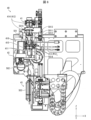
- FIG. 2 is a cross-sectional view taken along the line II in FIG. 1.
- FIG. FIG. 3 is a cross-sectional view taken along line II-II in FIG.
- the mixed injection device 1 includes a mixed injection unit 40 , a first transport section 110 , a second transport section 120 (transfusion container transport section), an air cleaning section 130 and a pair of inclined sections 160 . 2, illustration of the air cleaner 130 is omitted.
- the mixed injection unit 40 functions as a mixing section that mixes the drug with the infusion solution in the infusion container.
- the co-infusion unit 40 is located at a position facing the syringe shelf 10 and the vial shelf 20 and on the central back side of the co-infusion apparatus 1 .
- the first transport section 110 transports syringes from the syringe shelf 10 to the co-infusion unit 40 and vials from the vial shelf 20 to the co-infusion unit 40. It is configured.
- the second transport section 120 is configured to be able to transport the infusion container from the infusion shelf 30 to the mixed injection unit 40 . Co-injection processing can be executed in the co-infusion unit 40 by these transports.
- the first conveying unit 110 grabs the upper part of the trunk of the syringe stored in the syringe shelf 10, moves it leftward, rotates it 90 degrees on the XY plane, and conveys it to the co-infusion unit 40. Similarly, the first conveying unit 110 grabs the body of a vial stored in the vial shelf 20 , moves leftward, rotates 90 degrees on the XY plane, and conveys the vial to the co-infusion unit 40 .
- the first transport section 110 transports the syringes stored in the syringe shelf 10 to the later-described cap attaching/detaching section 250 (see FIG. 11) before transporting the syringes to the mixed injection unit 40 .
- the first transport section 110 can remove the needle cap attached to the needle of the syringe and attach the syringe with the needle cap removed to the co-injection unit 40 .
- the first transport unit 110 transports the syringes and vials after co-injection processing (syringes and vials that are no longer needed) to the trash box unit 70 .
- the second transport unit 120 sucks the body of the infusion container stored in the infusion shelf 30 , rotates it 90 degrees on the XY plane, and transports it to the mixed injection unit 40 .
- the second transport unit 120 sucks the body of the infusion container after drug injection, transports it to the printing/inspection unit 50, and injects the infusion container with the type information label (and unsuitability information label) attached.
- the container is transported to the infusion receiving section 60 .
- the air purifier 130 purifies and exhausts the air in the mixed injection device 1 . In this embodiment, it is provided on the upper part of the mixed injection device 1 .
- the air cleaned by the air cleaner 130 flows from the top to the bottom of the co-infusion apparatus 1 .
- the air cleaner 130 has, for example, a HEPA (High Efficiency Particulate Air) filter.
- the pair of inclined parts 160 are for transporting the infusion container after drug injection from the second transport part 120 to the infusion receiving part 60 by the weight of the infusion container.
- FIG. 4 is a diagram showing an example of a pair of inclined portions 160.
- the pair of inclined portions 160 are guide members that guide the drug-injected infusion container 503 adsorbed by the second conveying portion 120 to the infusion receiving portion 60 .
- the end portion on the side of the second conveying portion 120 is a rod-shaped member that is inclined so as to be higher than the end portion of the infusion receiving portion 60 . .
- the suction state of the infusion container 503 after drug injection with respect to the body is released.
- the infusion container 503 after drug injection slides on the pair of inclined portions 160 by its own weight and is dispensed to the infusion receiving portion 60 . That is, with the simple configuration of the pair of inclined portions 160, the infusion container 503 after drug injection can be dispensed to the infusion receiving portion 60 by its own weight.
- each member in the co-infusion apparatus 1 is not limited to the arrangement described above.
- vial shelf 20 may be provided above syringe shelf 10 .
- the arrangement positions of the syringe shelf 10 and the vial shelf 20 and the infusion solution shelf 30 may be reversed.
- the syringe shelf 10, the vial shelf 20, and the infusion shelf 30 are collectively provided on either the left or right side of the co-infusion device 1, and the co-infusion unit 40 is provided at a position different from the syringe shelf 10, the vial shelf 20, and the infusion shelf 30.
- the syringe shelf 10, the vial shelf 20, and the infusion shelf 30 may not be provided in a plurality of stages, and each may be provided in a single stage. Moreover, the arrangement positions of the printing/inspection unit 50 and the infusion receiving section 60 may be reversed. The layout of each member in the co-infusion apparatus 1 may be determined in consideration of user's convenience, ease of manufacture, and the like.
- the syringe side door 16 and/or the vial side door 27 may be provided on the side surface of the co-infusion device 1 .
- one syringe and one vial are filled from the front of the co-infusion device 1 .
- multiple syringes or multiple vials can be filled from the lateral side of the co-infusion device 1 . Therefore, by providing the syringe-side door 16 and/or the vial-side door 27 on the lateral side of the co-infusion apparatus 1, the user can more efficiently fill the syringe and the vial.
- the infusion shelf 30 has the same configuration as the syringe shelf 10 and the vial shelf 20, an infusion side door 34 may be provided on the lateral side of the co-infusion apparatus 1 . Again, the user can fill the infusion container more efficiently.
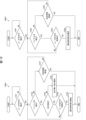
- FIG. 5 is a block diagram showing an example of the overall configuration of the co-infusion apparatus 1. As shown in FIG. As shown in FIG. 5, a control unit 140 and a storage unit 200 are provided. Note that FIG. 5 shows only the main hardware configuration that can be controlled by the control unit 140 among the hardware configurations provided in the co-infusion apparatus 1 .
- the control unit 140 comprehensively controls the co-infusion apparatus 1.
- the control unit 140 includes, for example, a syringe transport control unit 141, a vial transport control unit 142, a first transport control unit 143, a mixed injection unit control unit 144, a second transport control unit 145, a pushing control unit 147, and a printing/inspection unit control unit. 148 , a touch panel control unit 149 and a cap attachment/detachment control unit 150 .
- the touch panel control section 149 controls the touch panel 80 .
- Other configurations of the control unit 140 will be described later together with the description of each configuration.
- the storage unit 200 stores various programs and various data used by the control unit 140 .
- a specific configuration of the co-infusion apparatus 1 will be described with reference to FIG. 5 as well.
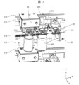
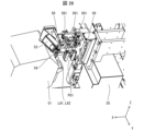
- FIG. 6 is a diagram showing an example of the configuration of the mixed injection unit 40.
- the mixed injection unit 40 includes a syringe holder 41 , a vial holder 42 , and an infusion container holder 43 .
- the operation of each member of the co-infusion unit 40 is controlled by the co-infusion unit control section 144 shown in FIG.
- the syringe holder 41 is a member that holds the syringe 501 .
- Syringe 501 consists of syringe 5011 , needle 5014 and plunger 5015 .
- Plunger 5015 is a plunger that moves in and out of syringe 5011 . By moving the plunger 5015 in and out of the syringe 5011 , it is possible to draw medicine or the like into the syringe 5011 or discharge the medicine or the like in the syringe 5011 .
- the syringe 5011 has a needle-side end 5012 to which the needle 5014 is attached, and a flange 5013 which is the end on the side opposite to the needle-side end 5012 and on which the plunger 5015 enters and exits.
- the vial holding portion 42 is a member that holds the vial 502 .
- the infusion container holder 43 is a member that holds the infusion container 503 .
- the syringe holding part 41 holds the lower part of the body of the syringe 501 (syringe 5011). Syringe holding portion 41 also holds a syringe at needle-side end 5012 and flange 5013 .
- the vial holding part 42 and the infusion container holding part 43 hold the necks of the vial 502 and the infusion container 503, respectively.
- the syringe holding portion 41 includes a pair of needle holding portions 411, a syringe holding portion 412, a base portion 415 (see FIG. 7), and a pair of first syringe holding portions 416.
- the base portion 415 is a member provided with a pair of second syringe holding portions 413 and a pair of needle clamping portions 411, which will be described later.
- the base 415 is provided so as to be vertically movable by the co-infusion unit control section 144 .
- a pair of needle clamping portions 411 are members that clamp the needle 5014 .
- a pair of needle clamping portions 411 clamp the needle 5014 to position the tip of the needle 5014 at a fixed position. As a result, even the bent needle 5014 can pierce the desired position (correct position) of the plug provided on the infusion container 503 during the co-injection process.
- the pair of needle clamping portions 411 function as electrodes. By causing the pair of needle clamping portions 411 to function as electrodes, the co-infusion unit control section 144 can detect a state in which a liquid (eg, drug or infusion) adheres to one of the needle clamping portions of the pair of needle clamping portions 411. .
- the co-infusion unit control section 144 can detect the state in which the liquid adheres to the pair of needle clamping sections 411 by detecting this conduction.
- the mixed injection unit control section 144 includes a liquid detection section 1441.
- the liquid detection section 1441 detects whether or not liquid is attached to the pair of needle clamping sections 411 .
- the co-infusion unit control section 144 with the needle 5014 positioned between the two needle clamping sections constituting the pair of needle clamping sections 411, clamps the needle 5014 between the two needle clamping sections.
- the needle 5014 is brought close to the position just before the needle 5014 (a position slightly separated from the needle 5014).
- the liquid detection unit 1441 can detect whether or not the liquid is attached to the pair of needle clamping portions 411 by determining whether or not to detect continuity between the pair of needle clamping portions 411 .
- the liquid detection section 1441 can detect that the liquid is attached to the pair of needle clamping sections 411 . Then, when the touch panel control unit 149 detects that the pair of needle clamping portions 411 is adhered with the liquid, the touch panel 80 displays an image indicating that the pair of needle clamping portions 411 is adhered with the liquid. You may In this case, the user can be prompted to clean the pair of needle clamping portions 411 . Therefore, it is possible to reduce the possibility of occurrence of the contamination described above.
- the co-infusion unit control section 144 controls the second transport section 110 to hold the syringe 501 in the syringe holding section 41 (that is, before the needle 5014 is positioned between the two needle clamping sections).
- the two needle clamps may be brought closer to the previous position. Even in this case, when the pair of needle clamping portions 411 are adhered with liquid, the pair of needle clamping portions 411 are electrically connected through the liquid. Therefore, the liquid detection section 1441 can detect that liquid is attached to the pair of needle clamping sections 411 .
- the pair of needle clamping parts 411 is an example of a needle holding part that holds the needle 5014 . That is, the syringe holding portion 41 does not necessarily have to include the pair of needle clamping portions 411 , and may include a member that holds the needle 5014 . In this case, apart from the pair of needle clamping portions 411, a pair of electrodes may be provided that are electrically connected when liquid adheres to the pair of needle clamping portions 411.
- FIG. In this specification, the term "a pair of members” does not necessarily mean "a pair" as long as the functions of the members can be exhibited.
- the pair of first syringe holders 416 are members that initially hold the syringes 501 transported from the syringe shelf 10 by the first transporter 110 .
- the pair of first syringe holding portions 416 sandwich the side surfaces of the syringe 5011 (eg, the lower portion of the syringe 5011) inserted into the pair of first syringe holding portions 416 from the left and right.
- the syringe clamping part 412 is a member that clamps the syringe 501 along the extending direction of the syringe 501 between the needle-side end 5012 and the flange 5013 .
- the syringe clamping portion 412 includes a pair of second syringe holding portions 413 and a pair of third syringe holding portions 414 .
- the pair of second syringe holders 413 is an example of a syringe holder that holds the needle-side end 5012 .
- the syringe clamping part 412 can clamp the syringe 501 along the extension direction of the syringe 501 .
- the force for holding the syringe 5011 is increased to some extent in order to fix the syringe 5011 so as not to slide in the extending direction of the syringe 501.
- the syringe 5011 will be deformed by the force that clamps the syringe 5011 .
- the syringe clamping part 412 can fix the syringe 5011 so as not to slide in the extending direction of the syringe 501 with a smaller force than when clamping the side surface of the syringe 5011 . Therefore, the possibility of deformation of the syringe 5011 can be reduced.
- the pair of second syringe holders 413 has a mortar shape into which the needle-side end 5012 can be fitted (see FIG. 7).
- the cross-sectional shape of the needle-side end portion 5012 has a triangular shape with the apex on the needle mounting side, or a trapezoidal shape in which the sides on the needle mounting side are shorter than the sides on the main body side of the syringe 5011 . Therefore, in the cross-sectional shape of the pair of second syringe holding portions 413, the portion to be inserted into the needle-side end portion 5012 has a triangular shape with a vertex on the lower side, or a trapezoidal shape whose lower side is shorter than its upper side.
- the pair of second syringe holders 413 can fit the needle-side end 5012 . Therefore, when the syringe clamping portion 412 clamps the syringe 501 , the entire needle 5014 can be protruded from the pair of second syringe holding portions 413 .
- the pair of second syringe holding portions 413 is not limited to the above shape as long as the shape allows the needle-side end portion 5012 to be fitted thereto.
- FIG. Reference numeral 7001 in FIG. 7 shows a state in which the syringe 501 is held by the pair of first syringe holders 416 .
- Reference numeral 7002 in FIG. 7 shows a state in which the pair of second syringe holding portions 413 hold the needle-side end portion 5012 .
- Reference numeral 7003 in FIG. 7 shows a state in which the pair of third syringe holders 414 hold the flange 5013 .
- Reference numeral 7004 in FIG. 7 shows a state in which the pair of needle clamping portions 411 clamp the needle 5014 .
- the first conveying section 110 causes the pair of first syringe holding sections 416 to hold the syringes 501 conveyed from the syringe rack 10 .
- the needle-side end portion 5012 is not fitted to the pair of second syringe holding portions 413 .
- the co-infusion unit control section 144 moves the base 415 upward. As a result, the needle-side end portion 5012 fits into the pair of second syringe holding portions 413 .
- the co-infusion unit controller 144 moves the base 415 further upward. Then, as indicated by reference numeral 7003 in FIG. 7, the pair of third syringe holding portions 414 come into contact with the flanges 5013 (the eaves of the syringe 5011). In this state, the syringe clamping part 412 clamps the syringe 501 along the extending direction of the syringe 501 between the needle-side end 5012 and the flange 5013 .
- the mixed injection unit control section 144 may detect the force applied in the extending direction of the syringe 501 .
- the co-infusion unit control section 144 moves the pair of second syringe holding sections 413 to the needle side end sections 5012 in a state where the needle side end sections 5012 are fitted. It can be determined that the third syringe holding portion 414 is in contact with the flange 5013 .
- the predetermined value may be determined in advance through experiments or the like.
- the co-infusion unit control section 144 stops the upward movement of the base section 415 when determining that the force has reached a predetermined value or more. Thereafter, as indicated by reference numeral 7004 in FIG. 7, the co-infusion unit control section 144 causes the pair of needle clamping sections 411 to clamp the needle 5014 by moving the pair of needle clamping sections 411 toward the needle 5014 side.
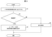
- FIG. 8 is a flow chart showing an example of processing for detecting the contamination state of the pair of needle clamping portions 411 .
- the co-infusion unit control section 144 causes the pair of third syringe holders 414 to abut against the flanges 5013 in a state where the needle side end portions 5012 are fitted to the pair of second syringe holders 413.
- the co-infusion unit control section 144 moves the two needle clamping sections that constitute the pair of needle clamping sections 411 closer to the previous position described above (S1).
- the liquid detection section 1441 determines whether or not the pair of needle clamping sections 411 are electrically connected (S2).
- the touch panel control unit 149 causes the touch panel 80 to display an image prompting the user to clean the pair of needle clamping portions 411. is displayed (S3).
- the liquid detection unit 1441 determines that the pair of needle clamping portions 411 are not conducting (NO in S2), the needle is clamped by the pair of needle clamping portions 411 (S4).
- the co-injection unit control section 144 moves the two needle clamping sections closer to the previous position before the first conveying section 110 causes the syringe holding section 41 to hold the syringe 501.
- the pair of needle holding sections 411 may hold the needle.
- FIG. 9 is a diagram showing an example of the configuration of the first conveying section 110.
- the first conveying section 110 includes a first claw portion 111 , a second claw portion 112 and a rotating shaft portion 113 .
- the operation of each member of the first conveying section 110 is controlled by the first conveying control section 143 .
- the movement of the first transporter 110 between the syringe shelf 10 or the vial shelf 20 and the mixed injection unit 40 is also controlled by the first transport controller 143 .
- the first claw portion 111 and the second claw portion 112 are members that clamp the upper portion of the syringe 5011 of the syringe 501 or the neck portion of the vial 502, respectively.
- the first claw portion 111 and the second claw portion 112 may have structures capable of holding the syringe 501 and the vial 502, respectively.
- the co-injection unit 40 holds the lower portion and both ends of the syringe 5011 of the syringe 501 and the barrel portion of the vial 502 . Therefore, in this embodiment, the first conveying unit 110 is configured to grip the upper part of the syringe 5011 of the syringe 501 or the neck of the vial 502 .
- the position where the co-infusion unit 40 sandwiches the syringe 501 or the vial 502 from both sides in the radial direction can be different from the position where the first transport section 110 sandwiches the syringe 501 or the vial 502 from both sides in the radial direction. Therefore, even if the first conveying portion 110 is brought close to the first syringe holding portion 416, the first conveying portion 110 and the first syringe holding portion 416 do not come into contact with each other. Therefore, first transport section 110 can bring syringe 501 or vial 502 closer to co-infusion unit 40 or can approach syringe 501 or vial 502 held by co-infusion unit 40 .
- the rotation shaft portion 113 is a shaft portion extending in the vertical direction, and rotates the first claw portion 111 and the second claw portion 112 on the XY plane.
- the first transport controller 143 causes the first claws 111 to hold the syringe 501 or the vial 502 to be used in the next co-infusion process to the co-infusion unit 40 .
- the first transport control unit 143 receives the syringe 501 or the vial 502 after the co-infusion process has been completed from the co-infusion unit 40 and causes the second claws 112 to clamp the syringe 501 or the vial 502 to the trash box unit 70 .
- the first transport control section 143 transports the first transport section 110 to the mixed injection unit 40 while the syringe 501 or the vial 502 is held by the first claw section 111 . Therefore, after the syringe 501 or the vial 502 is transported to the trash box section 70, the first transport section 110 holds the syringe 501 or the vial 502 used for the next co-infusion process and transports it to the co-infusion unit 40, which can be shortened.
- the first transport unit 110 transports the syringe 501 and the vial 502 and is a transport unit shared by the syringe 501 and the vial 502, it is not limited to this.
- a dedicated transport section for transporting the syringe 501 and a dedicated transport section for transporting the vial 502 may be provided.
- FIG. 10 is a diagram showing an example of the configuration of the second conveying section 120.
- the second conveying section 120 includes a suction section 121 and a third reading section 122 .
- the operation of each member of the second conveying section 120 is controlled by the second conveying control section 145 .
- the movement of the second transport section 120 between the mixed injection unit 40 and the printing/inspection unit 50 is also controlled by the second transport control section 145 .
- the adsorption part 121 is configured to be able to adsorb the body part 5031 of the infusion container 503 .
- the second transport section 120 may be configured to hold the infusion container 503 .
- the mixed injection unit 40 holds the neck of the infusion container 503 . Therefore, in the present embodiment, the second transport section 120 is configured to be able to hold the trunk section 5031 of the infusion container 503 . Thereby, the holding position of the infusion container 503 when the mixed injection unit 40 holds the infusion container 503 can be different from the holding position of the infusion container 503 when the second transport unit 120 holds the infusion container 503. .
- the second transport section 120 can bring the infusion container 503 closer to the co-infusion unit 40 or approach the infusion container 503 held in the co-infusion unit 40 . Therefore, it is possible to efficiently transfer the infusion container 503 to and from the mixed injection unit 40 .
- the third reading unit 122 reads label information included in the infusion label attached to the body 5031 of the infusion container 503 .
- the label information read by the third reading unit 122 includes, for example, information indicating the type of infusion. If the barcode contains label information, the third reading unit 122 may be realized by a barcode reader.
- FIG. 11 is a diagram showing an example of the configuration of the cap attaching/detaching part 250. As shown in FIG. The cap attachment/detachment part 250 attaches and detaches the needle cap 5016 of the syringe 501 . Syringes 501 loaded in syringe rack 10 have needle caps 5016 attached to needles 5014 .
- the cap attaching/detaching part 250 includes a cap inserting part 251 , a pair of cap clamping parts 252 and a solenoid 253 .
- the cap inserting portion 251 has a member into which the needle cap 5016 attached to the needle 5014 of the syringe 501 is inserted and presses the inserted needle cap 5016 against the syringe 5011 side with a spring (not shown).
- a pair of cap gripping portions 252 are portions that grip the needle cap 5016 under the control of a solenoid 253 .
- a solenoid 253 controls opening and closing of the pair of cap clamping portions 252 .
- a spring (not shown) is provided in the cap insertion portion 251, and the solenoid 253 is turned on when the spring is compressed to a predetermined length or less. As a result, the solenoid 253 closes the pair of cap clamping portions 252 . On the other hand, the solenoid 253 is turned off by the cap attachment/detachment control section 150 to open the pair of cap clamping sections 252 .
- FIG. 12 is a diagram showing how the cap attaching/detaching part 250 removes the needle cap 5016 from the syringe 501.
- first transport section 110 transports syringe 501 taken out from syringe rack 10 to cap attaching/detaching section 250 .
- the first transport section 110 inserts the needle cap 5016 of the syringe 501 into the cap attaching/detaching section 250 (specifically, the cap inserting section 251), and the needle cap 5016 pushes the spring.
- the member biased by is pushed in against the biasing force of the spring.
- the solenoid 253 When the length of the spring described above is reduced to a predetermined length or less, the solenoid 253 is turned on, and the pair of cap holding portions 252 are closed. As a result, the cap attaching/detaching portion 250 holds the needle cap 5016 therebetween. After that, as indicated by reference numeral 12003 in FIG. 12 , the first conveying section 110 moves away from the cap attaching/detaching section 250 . Needle cap 5016 is thereby removed from syringe 501 . Therefore, the first transport section 110 can transport the syringe 501 from which the needle cap 5016 has been removed to the mixed injection unit 40 .
- the needle 5014 may move together with the needle cap 5016 and the needle 5014 may be removed from the syringe 5011 .
- the cap attaching/detaching portion 250 clamps the needle cap 5016 .
- the needle cap 5016 presses the needle 5014 existing in the needle cap 5016 toward the syringe 5011 side, and the needle 5014 is more strongly attached to the syringe 5011 than the needle cap 5016. to fit. Therefore, when the needle cap 5016 is removed from the needle 5014, the needle 5014 can be in a state where it is not removed from the syringe 5011.
- the present invention is not limited to this.
- the first conveying section 110 stops immediately before or after inserting the needle cap 5016 into the cap attaching/detaching section 250 , and then the cap attaching/detaching section 250 moves to the first conveying section 110 side, whereby the needle cap 5016 is may be pushed into the cap attaching/detaching portion 250 .
- the first transport unit 110 transports the syringe 501 after mixed injection processing to the cap attaching/detaching unit 250, inserts the needle 5014 of the syringe 501 into the needle cap 5016 held by the cap attaching/detaching unit 250, and is fitted to needle cap 5016 .
- the cap attachment/detachment control section 150 turns off the solenoid 253, so that the pair of cap clamping sections 252 are opened.
- the first conveying section 110 moves away from the cap attaching/detaching section 250 .
- the needle cap 5016 can be attached to the syringe 501 after co-injection processing. Therefore, the first transport section 110 can dispose of the syringe 501 attached with the needle cap 5016 after the co-injection process to the trash box section 70 .
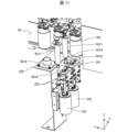
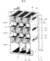
- FIG. 13 is a perspective view showing an example of the overall configuration of the syringe shelf 10 and the vial shelf 20.
- FIG. 14 is a perspective view showing an example of the configuration of one syringe shelf 10 and one vial shelf 20.
- FIG. 15 is a perspective view showing an example of the configuration of one syringe shelf 10 and one vial shelf 20 when viewed from a direction different from that of FIG.
- FIG. 16 is a diagram showing an example of the configuration of one syringe shelf 10 and one vial shelf 20 when viewed from the first transport section 110 side.
- the syringe shelf 10 includes a plurality of device holding units 11, a device transport unit 12, an object detection unit 13, a syringe detection unit 14, a needle detection unit 15, and a syringe detection unit. a portion 17;
- the members related to the transportation of the syringes 501 in the syringe shelf 10 are controlled by the syringe transportation control section 141 .
- the instrument holding part 11 is also attached to the attachment part 1211 of the instrument conveying part 12 shown in FIG. 13, its illustration is omitted.
- the syringe rack 10 Prior to the mixed injection process, the syringe rack 10 is filled with syringes 501 by the user. Syringes 501 are loaded into syringe shelf 10 with needle caps 5016 attached to needles 5014 .
- a plurality of holes 172 are formed in a plate member 171 that defines each syringe shelf 10. As shown in FIG. As a result, for example, the air cleaned by the air cleaner 130 (see FIG. 3) can efficiently flow from the top to the bottom of the co-infusion apparatus 1 . Therefore, the entire space in the co-infusion apparatus 1 can be kept clean.
- a plurality of device holding portions 11 are members capable of holding syringes 501 .
- one syringe 501 is held in one device holding portion 11 , but a plurality of syringes 501 may be held in one device holding portion 11 .
- the instrument holding section 11 includes a pair of free rollers 1111 and a pair of instrument clamping sections 1112 .
- a pair of device holding portions 1112 hold the syringe 501 therebetween.
- the pair of instrument clamping portions 1112 clamp the flange 5013 of the syringe 501 .
- the instrument holder 11 holds the neck of the syringe 501 .
- the pair of instrument clamping portions 1112 are provided above the syringe shelf 10 .
- the syringe 501 is held by the device holding portion 11 so that the needle cap 5016 (needle 5014) is positioned on the lower side.
- the pair of device holding portions 1112 are provided at such a height that the syringe 501 does not touch the plate member 171 when the syringe 501 is held by the device holding portion 11 .
- the syringe 501 in the co-infusion unit 40, the syringe 501 is arranged so that the needle 5014 is positioned on the lower side. Therefore, a pair of instrument clamping portions 1112 are provided above the syringe shelf 10 .
- the cap attaching/detaching part 250 (see FIG. 11) is also arranged in the lower part of the co-infusion apparatus 1 so that the cap inserting part 251 faces upward.
- the pair of device clamping portions 1112 may be provided below the syringe shelf 10 .
- the cap attaching/detaching part 250 may be arranged in the upper part of the co-infusion apparatus 1 so that the cap inserting part 251 faces downward.
- the pair of instrument holding parts 1112 are biased toward each other so that the syringe 501 can be held.
- the pair of instrument clamping portions 1112 are spaced apart to an extent smaller than the width of the flange 5013 when the flange 5013 is not clamped.
- the pair of instrument clamping parts 1112 move according to the shape of the flanges 5013 .
- the syringe 501 can be held between the pair of device holding portions 1112 .
- a pair of free rollers 1111 which have rotation shafts extending in the vertical direction and are rotatable on the XY plane, are provided under the tip portions of the pair of instrument holding portions 1112.
- the pair of free rollers 1111 hold the vicinity of the flange 5013 of the syringe 5011 held by the pair of device holding portions 1112 .
- the instrument transporter 12 is a member that transports at least one of the plurality of instrument holders 11 to the work area Ar1.
- the instrument conveying section 12 is an endless rotating member to which a plurality of instrument holding sections 11 are connected. Therefore, in the present embodiment, the instrument transporter 12 transports the instrument holders 11 one by one to the work area Ar1.
- the instrument transporter 12 may be a transporter that transports a plurality of instrument holders 11 to the work area Ar1 at once.
- the working area Ar1 is defined by the user holding the syringe 501 on at least one of the plurality of device holding portions 11 and by at least one of the plurality of device holding portions 11 holding the syringe 501 .
- This is the area where the user removes the injected syringe 501 .
- the work area Ar1 functions as a filling place where the syringe 501 can be filled and also functions as a recovery place where the syringe 501 can be recovered.
- the work area Ar1 is an area where the user holds the syringe 501 on one device holding portion 11 and where the user removes the syringe 501 held by one device holding portion 11.
- the work area Ar1 is located on the side of the syringe-side door 16 shown in FIG. This allows the user to fill the device holding portion 11 with the syringe 501 and remove the syringe 501 held by the device holding portion 11 from the side of the syringe side door 16 .
- the syringe-side door 16 functions as a door capable of shielding the user's access to the work area Ar1.
- the working area Ar1 may function only as an area where the user holds the syringe 501 on at least one of the plurality of device holding portions 11. In this case, the area where the user removes the syringe 501 held by the device holding portion 11 may be provided at a different position from the work area Ar1. Also, the working area Ar1 may function only as an area where the user removes the syringe 501 held by the device holding portion 11 . In this case, the area where the user holds the syringe 501 on the device holder 11 may be provided at a position different from the work area Ar1.
- the instrument transport section 12 transports another instrument holding section 11 instead of the instrument holding section 11 located in the work area Ar1, triggered by detection of the user's motion.
- the instrument transporter 12 changes the instrument holder 11 positioned in the work area Ar1 by rotating counterclockwise, for example.
- this transport operation instead of the instrument holding part 11 holding the syringe 501 in the working area Ar1, another instrument holding part 11 not holding the syringe 501 can be transported to the working area Ar1. Therefore, the user only needs to hold the syringe 501 on the instrument holder 11 transported to the work area Ar1. Therefore, it is possible to reduce the user's trouble in filling the syringe 501 .
- the equipment transport unit 12 moves the work area Ar1.
- another instrument holder 11 is transported.
- the user's hand is inserted into the working area Ar1, and after the user holds the syringe 501 in the instrument holding part 11, when the user's hand leaves the working area Ar1, the instrument conveying part 12 moves to the working area Ar1.
- another instrument holder 11 is conveyed. Therefore, the instrument transporting part 12 can transport another instrument holding part 11 to the work area Ar1 without the user giving a transport instruction to the co-infusion apparatus 1 .
- the instrument transporter 12 does not transport another instrument holder 11 to the work area Ar1. Therefore, the safety of the user involved in the filling operation of the syringe 501 can be ensured.
- the device conveying unit 12 detects another device held in the work area Ar1 when the syringe detection unit 14 detects the syringe 501 held by the device holding unit 11. Portion 11 is transported. Therefore, after the user holds the syringe 501 in the instrument holding part 11 located in the working area Ar1, the instrument transporting part 12 can transport another instrument holding part 11 to the working area Ar1. Therefore, it is possible to reduce the possibility that the instrument conveying section 12 conveys another instrument holding section 11 to the work area Ar1 in a state where the instrument holding section 11 does not hold the syringe 501 .
- the object detection unit 13 is a member that detects objects inserted into the work area Ar1.
- the object detection unit 13 detects the user's hand or arm inserted into the work area Ar1.
- the object detection unit 13 uses the side of the syringe shelf 10 where the syringe side door 16 shown in FIG. .
- the object detection unit 13 is provided at a position corresponding to a region of the wall portion of the syringe shelf 10 between the syringe-side door 16 and the instrument holder 11 located in the work area Ar1.
- a plurality of object detection units 13 are provided along the vertical direction of the syringe rack 10 in order to improve the accuracy of object detection in the work area Ar1.
- the object detection unit 13 may be, for example, an optical sensor configured by an emission unit that emits light and a light receiving unit that is provided at a position facing the emission unit and receives the light from the emission unit. In this case, the object detection unit 13 detects the object when the light receiving unit does not receive light.
- the object detection unit 13 may be any type of sensor as long as it can detect the object inserted into the work area Ar1. In this regard, the same applies to other detection units (sensors). For example, when detecting a target object, the target object detection unit 13 outputs a detection signal to the control unit 140 while detecting the target object.
- the syringe detection unit 14 is a member that detects the syringe 501 held by the equipment holding unit 11 located in the work area Ar1.
- the syringe detector 14 functions as an instrument detector that detects the syringe held by the instrument holder 11 located in the work area Ar1.
- the syringe detector 14 detects the syringe 5011 when the syringe 501 is held by the device holder 11 .
- the syringe detection unit 14 is provided on the wall portion of the syringe shelf 10 at a position facing the instrument holder 11 located in the work area Ar1.
- the syringe detector 14 may be, for example, an optical sensor that detects an object by emitting light and receiving light reflected by the object. For example, when syringe 5011 is detected, syringe detector 14 outputs a detection signal to controller 140 .
- the needle detection unit 15 detects the needle 5014 of the syringe 501 held by the device holding unit 11 located in the work area Ar1.
- needle detector 15 detects needle cap 5016 attached to needle 5014 .
- the needle detector 15 is provided on the wall portion of the syringe shelf 10 at a position facing the device holding portion 11 located in the work area Ar1.
- the needle detection unit 15 is arranged in the same row as the syringe detection unit 14 along the vertical direction, but they do not necessarily have to be in the same row.
- Needle detector 15 may be, for example, an optical sensor similar to syringe detector 14 .
- the needle detection unit 15 may function as the syringe detection unit. In this case, the syringe detector 14 may not be provided.
- the needle detection section 15 outputs a detection signal to the control section 140 .
- a plurality of needle detection portions 15 may be provided in the same row at predetermined intervals along the vertical direction.
- the controller 140 can estimate the length of the needle 5014 attached to the syringe 501 held by the device holder 11 based on whether or not the needle cap 5016 is detected by each of the needle detectors 15 . Therefore, the control section 140 can determine whether the needle 5014 is suitable for attachment to the syringe 501 held by the device holding section 11 . Then, when the control unit 140 determines that the needle 5014 to be attached to the syringe 501 is unsuitable, the touch panel control unit 149 may cause the touch panel 80 to display an image indicating the unsuitability.
- the storage unit 200 may store information indicating presence/absence of detection by each needle detection unit 15 and the length of the needle 5014, and information indicating the thickness (diameter) of the syringe 501 and the length of the needle 5014. . Also, a plurality of needle detection units for detecting the length of needle 5014 may be provided separately from needle detection unit 15 .
- the syringe detection unit 17 is a member that can detect the thickness of the syringe 5011 .
- the syringe detector 17 is provided at a position where the syringe 5011 being transported by the equipment transporter 12 can be detected on the wall part of the syringe shelf 10 .
- the syringe detection unit 17 may be provided, for example, such that the object detection area by the syringe detection unit 17 is inclined with respect to the XY plane.
- the syringe detector 17 may be, for example, an optical sensor similar to the syringe detector 14 .
- the syringe detection unit 17 may function as a syringe detection unit. In this case, the syringe detector 14 may not be provided.
- the syringe detection unit 17 detects the syringe 5011, it outputs a detection signal to the control unit 140 while the syringe 5011 is being detected.
- the storage unit 200 stores information indicating the speed of the equipment conveying unit 12 in front of the syringe detection unit 17 and information indicating the thickness of various syringes 5011 that can be used in the co-infusion apparatus 1 .
- the control unit 140 multiplies the detection time by the speed of the equipment conveying unit 12 to obtain the thickness of the syringe 5011 passing in front of the syringe detection unit 17. calculate.
- control unit 140 can specify the thickness of syringe 5011 that has passed in front of syringe detection unit 17 (that is, the type of syringe 501). Therefore, the control unit 140 determines that, for example, the syringe 501 held by the equipment holding unit 11 is appropriate as the syringe 501 (the syringe 501 to be filled in the syringe shelf 10) used for aspirating the drug indicated in the preparation data. can determine if there is Then, when the control unit 140 determines that the syringe 501 held by the device holding unit 11 is not suitable as the syringe 501 used for aspirating the medicine, the touch panel control unit 149 indicates that it is unsuitable. An image may be displayed on the touch panel 80 . Information indicating the type of syringe 501 used to aspirate the medicine indicated in the preparation data may be stored in the storage unit 200 together with the preparation data.
- the storage unit 200 information identifying each instrument holding part 11, information indicating the type of syringe 501 held in each instrument holding part 11, information indicating the transport position of each instrument holding part 11, may be associated and stored.
- the first transport control unit 143 can identify the type of syringe 501 that the first transport unit 110 takes out from the device holding unit 11 . Therefore, the first transport section 110 can transport the appropriate syringe 501 to the mixed injection unit 40 .
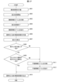
- FIG. 18 is a flow chart showing an example of processing when starting to transport the equipment holding part 11 .
- Reference numeral 18001 in FIG. 18 is a flowchart showing an example of processing when the syringe transport control section 141 starts transporting the instrument holding section 11 .
- the syringe transport control unit 141 determines whether or not the object detection unit 13 has detected the user's hand inserted into the work area Ar1 (S101). The syringe transport control unit 141 determines that the user's hand has been detected when the detection signal is received from the object detection unit 13 . When the syringe transport control unit 141 determines that the user's hand is not detected (NO in S101), it continues the process of S101.
- the syringe transport control unit 141 determines whether the user's hand has been detected (YES in S101), it determines whether the syringe detection unit 14 has detected the syringe 5011 (S102). Syringe transport control unit 141 determines that syringe 5011 has been detected when a detection signal is received from syringe detection unit 14 .
- the syringe transport control unit 141 determines whether the syringe 5011 has been detected (YES in S102), it determines whether the needle 5014 has been detected by the needle detection unit 15 (S103). Syringe transport control section 141 determines that needle 5014 has been detected when a detection signal is received from needle detection section 15 .
- the syringe transport control unit 141 determines whether the needle 5014 has been detected (YES in S103), it determines whether the user's hand inserted into the work area Ar1 has not been detected (S104). For example, the syringe transport control unit 141 determines that the user's hand has not been detected when the detection signal continuously received from the object detection unit 13 is stopped in S101. When the syringe transport control unit 141 determines that the user's hand is not undetected (NO in S104), the process returns to S102.
- the syringe transport control unit 141 determines that the user's hand has not been detected (YES in S104)
- the syringe transport control unit 141 controls the instrument transport unit 12 to replace the instrument holding unit 11 located in the work area Ar1 with another device. , is transported to the work area Ar1 (S105).
- the co-infusion apparatus 1 includes a detection unit that detects opening and closing of the syringe-side door 16, and the syringe transport control unit 141 receives a detection signal from the detection unit to indicate that the syringe-side door 16 is in an open state. can determine whether Moreover, when the syringes 501 are held by all the device holding portions 11 , the syringe transfer control portion 141 does not have to transfer the device holding portions 11 .
- the syringe transport control unit 141 determines in S102 that the syringe 5011 has not been detected (NO in S102), it determines whether the syringe 5011 has not been detected for a predetermined period of time (S107). Specifically, the syringe transport control unit 141 determines whether or not a predetermined time has passed without receiving a detection signal from the syringe detection unit 14 . Timing of the predetermined time may be started, for example, when a detection signal is received from the object detection unit 13 . Also, as the predetermined time, for example, a time suitable for ending this process may be set.
- the touch panel control unit 149 displays an image indicating that there is no needle on the touch panel 80. (S106). This allows the user to recognize syringes 501 that are unsuitable for mixed injection processing. Note that the processes of S102 and S103 do not necessarily have to be executed.
- the syringe transport control unit 141 is triggered by the user's motion detection that the target object detection unit 13 has stopped detecting the user's hand after detecting the user's hand.
- the instrument holding part 11 located at is changed to another instrument holding part 11 .
- the syringe transport control unit 141 may be triggered by the user's transport instruction to transport another instrument holding part 11 instead of the instrument holding part 11 located in the work area Ar1. .
- the syringe transport control unit 141 may receive a user's transport instruction via the touch panel 80, for example.
- FIG. 17 is a diagram for explaining the device holding portion 21. As shown in FIG.
- the vial shelf 20 includes a plurality of instrument holders 21, an instrument transporter 22, an object detector 23, and a vial detector . Further, as shown in FIGS. 16 and 17, a first reading section 25 (reading section) and a roller driving section 26 are provided.
- the vial transport control unit 142 controls the members related to the transport of the vials 502 on the vial shelf 20 .
- the instrument holding part 21 is also attached to the attachment part 221 of the instrument conveying part 22 shown in FIG. 13, the illustration thereof is omitted.
- the vial rack 20 Prior to co-infusion processing, the vial rack 20 is filled with vials 502 by the user. Further, like the syringe shelf 10, the plate member 171 defining each vial shelf 20 has a plurality of holes 172 formed therein.
- the equipment holding part 21 is a member capable of holding the vial 502 .
- one vial 502 is held in one device holding portion 21, but a plurality of vials 502 may be held in one device holding portion 21.
- FIG. 1 is a member capable of holding the vial 502 .
- one vial 502 is held in one device holding portion 21, but a plurality of vials 502 may be held in one device holding portion 21.
- the instrument holding section 21 includes a pair of free rollers 211, a pair of instrument clamping sections 212, a drive roller 213, and a first magnet 214.
- a pair of instrument holding portions 212 hold the vial 502 therebetween.
- the pair of instrument clamps 212 clamp the neck of the vial 502 .
- the pair of device clamping portions 212 are provided above the vial shelf 20 . The pair of device clamping portions 212 are provided at such a height that the vial 502 does not come into contact with the plate member 171 when the vial 502 is held by the device holding portion 21 .
- the pair of instrument clamping parts 212 are biased toward each other so that the vial 502 can be clamped.
- the pair of instrument clamping portions 212 are spaced apart by a distance smaller than the width of the neck of the vial 502 when the neck is not clamped.
- the pair of instrument clamping parts 212 move according to the shape of the neck. As a result, the pair of device clamping portions 212 can clamp the vial 502 .
- a pair of free rollers 211 that have rotation shafts extending in the vertical direction and are rotatable on the XY plane are provided at the distal end portions of the pair of material holding portions 212 .
- the pair of free rollers 211 are on the side where the pair of instrument clamping portions 212 are pivotally supported, and together with the driving roller 213 provided at a position facing the central portion of the pair of free rollers 211, the neck portion of the vial 502 is moved.
- the vial 502 is held by supporting it at three points.
- the drive roller 213 rotates while holding the vial 502, the vial 502 also rotates.
- the pair of free rollers 211 also rotate.
- a first magnet 214 is provided above the drive roller 213 .
- the drive roller 213 and the first magnet 214 are connected to a common rotating shaft extending in the vertical direction, and are rotatable on the XY plane.
- the driving roller 213 also rotates.
- S poles and N poles are alternately arranged on the outer peripheral surfaces of the first magnet 214 and the second magnet 261 .
- the instrument transporter 22 is a member that transports at least one of the plurality of instrument holders 21 to the work area Ar2.
- the instrument conveying section 22 is an endless rotary member to which a plurality of instrument holding sections 21 are connected. Therefore, in the present embodiment, the instrument transporter 22 transports the instrument holders 21 one by one to the work area Ar2.
- the instrument transporter 22 may be a transporter that transports a plurality of instrument holders 21 to the work area Ar2 at once.
- the working area Ar2 is an area where the user holds the vial 502 in at least one of the plurality of device holding portions 21, like the working area Ar1.
- the work area Ar2 is an area where the user removes the vial 502 held by at least one of the plurality of device holders 21 .
- the work area Ar2 is positioned on the side of the vial-side door 27 shown in FIG.
- the vial-side door 27 functions as a door capable of shielding the user's access to the work area Ar2.
- the work area Ar2 may be an area that functions only as an area for holding the vial 502, or an area that functions only as an area for removing the vial 502, like the work area Ar1.
- the instrument transport section 22 has the same functions as the instrument transport section 12 described below. That is, the instrument transporter 22 transports another instrument holder 21 in place of the instrument holder 21 positioned in the work area Ar2 when the user's motion is detected.
- the instrument transporter 12 changes the instrument holder 21 located in the work area Ar2 by rotating counterclockwise, for example. Triggered by the detection of the user's motion by the object detection unit 23, the device transport unit 22 transports another device holding unit 11 to the work area Ar2.
- the device conveying unit 12 is triggered by the detection of the vial 502 held by the device holding unit 21 by the vial detection unit 24. Portion 11 is transported. With these configurations, the instrument transport section 22 can achieve the same effects as the instrument transport section 12 .
- the vial transport control unit 142 transports another device holding unit 21 instead of the device holding unit 21 located in the work area Ar2, for example, triggered by a user's transport instruction. good too.
- the vial transport control unit 142 may receive a user's transport instruction via the touch panel 80, for example.
- the vial 502 is provided with a rubber plug that closes the opening and a lid that covers the rubber plug.
- the needle of the syringe 501 held in the mixed injection unit 40 is pierced through the rubber plug.
- the vials 502 are filled in the vial shelf 20 with the lids removed.
- a camera (not shown) may be provided on the vial shelf 20 and the top of the vial 502 may be imaged by the camera.
- the control unit 140 can determine the presence or absence of the lid based on the imaging result of the camera.
- the touch panel control unit 149 may display an image on the touch panel 80 prompting the user to fill the vial 502 into the device holding unit 21 with the lid removed.
- the object detection unit 23 is a member that detects objects inserted into the work area Ar2. In this embodiment, the object detection unit 23 detects the user's hand or arm inserted into the work area Ar2.
- the arrangement of the object detector 23 on the vial shelf 20 is the same as the arrangement of the object detector 13 on the syringe shelf 10 , and the specific example and function of the object detector 23 are also the same as the object detector 13 .
- the vial detection unit 24 detects the vial 502 held by the equipment holding unit 21 located in the work area Ar2.
- the vial detector 24 functions as a device detector that detects the syringe held by the device holder 21 located in the work area Ar2.
- the arrangement of the vial detectors 24 on the vial shelf 20 is the same as the arrangement of the syringe detectors 14 on the syringe shelf 10 , and the specific examples and functions of the vial detectors 24 are also the same as the syringe detectors 14 .
- the first reading unit 25 reads the type information indicating the type of the drug contained in the vial 502 indicated on the surface of the vial 502 in a portion of the transport path along which the device transporting unit 22 transports the plurality of device holding units 21. It is a member that reads
- the vial 502 may be attached with a barcode recording type information. In this case, the first reading unit 25 may be a barcode reader.
- the first reading unit 25 is arranged at a position where it can read the barcode of the vial 502 transported to the predetermined position.
- the predetermined position may be the position from which the first transporter 110 takes out the vial 502 .
- the control unit 140 can recognize the type of drug contained in the vial 502 immediately before it is taken out. Therefore, the first transport section 110 can transport vials 502 that are suitable as the vials 502 to be transported to the co-infusion unit 40 .
- the first reading unit 25 is arranged behind the predetermined position when the vial shelf 20 is viewed from the first conveying unit 110 side.
- the first reading unit 25 starts reading the barcode of the vial 502 when the vial-side door 27 is closed.
- the control unit 140 starts the reading operation by the first reading unit 25 when it detects that the vial-side door 27 is closed.
- the vial-side door 27 is closed, which triggers the display of the vial 502 shown in each of the plurality of vials. Barcodes (type information) can be read sequentially. Therefore, the barcode reading by the first reading unit 25 can be performed efficiently.
- the device conveying unit 22 moves the vial 502 to the corresponding position. can be transported to a location.
- the equipment conveying unit 22 allows the first reading unit 25 to read the barcode of the next vial 502. , may transport the next vial 502 to said position.
- the roller driving section 26 is a motor that rotates the second magnet 261 attached to the roller driving section 26 in order to rotate the driving roller 213 of the instrument holding section 21 .
- a rotating shaft of the roller driving unit 26 extends in the Y-axis direction, and a second magnet 261 is attached to the rotating shaft. This allows the second magnet 261 to rotate on the XZ plane.
- the vial transport control unit 142 may drive the roller driving unit 26 when the vial 502 is positioned at the bar code reading position of the first reading unit 25, for example.
- the first magnet 214 of the instrument holding part 21 is arranged on the upper part of the instrument holding part 21 .
- the arrangement position of the equipment holding part 21 and the roller driving part 26 is defined so that the first magnet 214 and the second magnet 261 are separated by a distance that allows them to receive each other's magnetism.
- the second magnet 261 When the vial transport control unit 142 drives the roller driving unit 26, the second magnet 261 also rotates.
- the first magnet 214 rotates in conjunction with the rotation of the second magnet 261 .
- the driving roller 213 connected to the rotation shaft common to the first magnet 214 rotates, thereby rotating the vial 502 in contact with the driving roller 213 .
- the first reading unit 25 can read the barcode regardless of the position of the barcode on the surface of the vial 502 .
- the first reading unit 25 may start reading the barcode of the vial 502 in response to a user's reading instruction.
- the control unit 140 may receive a user's reading instruction via the touch panel 80, for example.
- Reference numeral 18002 in FIG. 18 is a flowchart showing an example of processing when the vial transport control section 142 starts transporting the device holding section 21 .
- the vial transport control unit 142 determines whether or not the user's hand inserted into the work area Ar2 has been detected (S201).
- the vial detection unit 24 determines whether the vial 502 has been detected (S202). The vial transport control unit 142 determines that the vial 502 has been detected when the detection signal is received from the vial detection unit 24 .
- the vial transport control unit 142 controls the device transport unit 22 to replace the device holding unit 21 located in the work area Ar2 with another device.
- the instrument holder 21 is transported to the work area Ar2 (S205).
- the vial transport control unit 142 determines whether the vial 502 has been in the undetected state for a predetermined period of time, as in S107 of reference numeral 18001. (S205).
- FIG. 19 is a diagram for explaining how to efficiently fill the vial 502 held by the device holding portion 21. As shown in FIG. Note that the filling efficiency improvement example described below may be applied to the filling efficiency improvement of the syringe 501 held in the device holding portion 11 .
- Reference numeral 19001 in FIG. 19 is a diagram showing a state in which two instrument holders 21 that do not hold vials 502 exist at different positions.
- Reference numeral 19002 in FIG. 19 shows a state in which two instrument holders 21 that do not hold vials 502 are positioned adjacent to each other.
- a state in which the vial 502 is not held in two or more of the plurality of device holding portions 21 may occur.
- a device holding portion 21 that does not hold a vial 502 can also be referred to as an empty device holding portion 21 .
- at least two empty instrument holding parts 21 among them may exist at positions that are not adjacent to each other.
- Such a state can occur, for example, when the first transport section 110 transports the vial 502 used for co-infusion processing to the co-infusion unit 40 .
- the control unit 140 may determine the device holding unit 21 to be an empty device holding unit 21 . Further, the control section 140 may determine whether or not two empty instrument holding sections 21 are adjacent to each other based on the information identifying the instrument holding sections 21 .
- the control unit 140 determines that the two empty instrument holding units 21 are not adjacent to each other, for example, during the idle time of the first transport unit 110, the following processing is executed.
- the control unit 140 moves the vials 502 held by the device holders 21 so that the empty device holders 21 are adjacent to each other, as indicated by reference numeral 19002 in FIG.
- the device transport unit 22 transports the device holding unit 21 adjacent to the empty device holding unit 21 to the position where the first transport unit 110 takes out the vial 502. .
- the first transport unit 110 takes out and holds the vial 502 under the control of the first transport control unit 143 .
- the instrument conveying section 22 conveys the other empty instrument holding section 21 to the position where the first conveying section 110 takes out the vial 502 .
- the first conveying unit 110 causes the empty device holding unit 21 to hold the vial 502 to be held.
- Reference numeral 19003 in FIG. 19 is a diagram showing an example of a case where there are a plurality of adjacent empty instrument holders 21 .
- the vial transport control unit 142 moves the adjacent empty device holding unit 21. search for.
- the vial transport control unit 142 determines the transport order of the empty instrument holders 21 to the work area Ar2 in descending order of the number of consecutively adjacent empty instrument holders 21 .
- the vial transport control unit 142 sets the transport order to the portions SP3 of the three consecutively adjacent vacant device holding portions 21 and the portions SP2 of the two adjacent vacant device holding portions 21.
- one empty instrument holder 21 (the part denoted by symbol SP1).
- the equipment transporter 22 transports the parts SP1 to SP3 to the work area Ar2 in this transport order.
- the vials 502 can be filled in order from the part with the largest number of continuously adjacent empty instrument holding parts 21 . Therefore, also in this case, the above-described time interval can be shortened.
- FIG. 20 and 21 are perspective views showing an example of the configuration of the infusion shelf 30.
- FIG. FIG. 21 is a diagram in which a part of the wall constituting the infusion shelf 30 is removed.
- FIG. 22 is a perspective view showing an example when the infusion shelf 30 is viewed from the rear side.
- the infusion shelf 30 includes a push-in portion 31, a first infusion detection portion 32, a push-in transport portion 35, and a pair of rail portions 36 (extending portions).
- a second infusion detection unit 33 and a shutter 37 are provided.
- the infusion shelf 30S and the infusion shelf 30L are provided as the infusion shelf 30 as described above. are identical.
- members related to transportation of the infusion container 503 in the infusion shelf 30 are controlled by the push-in controller 147 .
- the infusion shelf 30 Prior to the mixed injection process, the infusion shelf 30 is filled with the infusion container 503 by the user. Further, like the syringe shelf 10 and the vial shelf 20, the plate member 301 defining each infusion shelf 30 has a plurality of holes 302 formed therein.
- the pair of rail portions 36 are members provided inside the infusion shelf 30 and extending from the side of the infusion side door 34 (see FIG. 1) toward the back side of the co-infusion apparatus 1 (that is, in the Y-axis direction).
- the end portion located on the infusion side door 34 side is the door side end portion 361
- the end portion located on the back side of the co-infusion apparatus 1 is the back side end portion 362 .
- At least one infusion container 503 can be suspended from the pair of rail portions 36 .
- the neck portion of the infusion container 503 can be hung between the pair of rail portions 36 .
- the pair of rail portions 36 are provided with a space enough to hold the neck portion of the infusion container 503 .
- the pair of rail portions 36 By providing the pair of rail portions 36 , when filling the infusion shelf 30 with a plurality of infusion containers 503 , the user only needs to sequentially hang the plurality of infusion containers 503 from the pair of rail portions 36 . Therefore, the user can easily fill the infusion shelf 30 with a plurality of infusion containers 503 .
- each infusion shelf 30 is provided with three pairs of rail portions 36 .
- the number of pairs of rail portions 36 provided on each infusion shelf 30 is not limited to three.
- each of the pair of rail portions 36 may be filled with the same type of infusion container (the same type of infusion container and the same size of the infusion container).
- each of the pair of rail portions 36 may be filled with a different type of infusion container.
- the push-in portion 31 is movable along the pair of rail portions 36, and is a member that pushes the infusion container 503 suspended from the pair of rail portions 36 from the door-side end portion 361 to the back-side end portion 362. .
- the push-in portion 31 is connected to the push-in transport portion 35 .
- the pushing conveying portion 35 is provided along the pair of rail portions 36 .
- the pushing conveying portion 35 can move the pushing portion 31 along the pair of rail portions 36 by operating under the control of the pushing control portion 147 .
- the push-and-transport section 35 may be, for example, an endless rotating member.
- the size of the push-in portion 31 and the distance between the pair of rail portions 36 and the push-in transport portion 35 are determined so that the infusion container 503 suspended on the pair of rail portions 36 can be pushed in by the movement of the push-in portion 31 .
- a positional relationship is defined.
- the push-in portion 31 When the infusion-side door 34 is open, the push-in portion 31 is positioned on the door-side end portion 361 side and at a position PO0 that does not interfere with filling of the infusion container 503 (suspension to the pair of rail portions 36).
- the push-in control unit 147 controls the push-in transport unit 35 to perform the push-in operation.
- Part 31 may be moved to the above position.
- the push-in section 31 pushes the infusion container 503 suspended on the pair of rail sections 36 from the door side end 361 to the back side end 362 .
- the push-in controller 147 controls the push-in transport unit 35 to move the push-in unit 31 from the position PO0 to the far end 362.
- the user can move the infusion container 503 to the back end 362 and cause the second transport section 120 to take out the infusion container 503 simply by filling the door end 361 with the infusion container 503 . That is, the second conveying unit 120 can efficiently take out the infusion container 503 suspended from the pair of rails 36 .
- the second conveying unit 120 takes out the infusion container 503 positioned at the back end 362 in a state in which a plurality of infusion containers 503 are suspended from the pair of rails 36 .
- the pushing unit 31 pushes the remaining infusion container 503 suspended on the pair of rails 36 from the door end 361 to the back end 362 . enter.
- the pushing control unit 147 controls the push-in conveying unit 35 to move the pushing unit 31 to the far side. Move further to end 362 .
- the second transport section 120 can take out the infusion container 503 more efficiently.
- the first infusion detection unit 32 detects the infusion container 503 filled in the infusion shelf 30 . Also, the first infusion detection unit 32 may detect the infusion container 503 taken out from the infusion shelf 30 . That is, the first infusion detection unit 32 may function as a count sensor that counts the number of infusion containers 503 filled in the infusion shelf 30 . As shown in FIGS. 20 and 21 , the first infusion detection unit 32 is provided on the door-side end 361 side of the wall constituting the infusion shelf 30 . Also, the first infusion detection unit 32 is provided for each pair of rail portions 36 . The first infusion detection unit 32 may be, for example, an optical sensor including an emission unit and a light reception unit, like the object detection unit 13 described above.
- two sensors are provided adjacent to each other in the Y-axis direction as the first infusion detection unit 32 .
- the control unit 140 recognizes that the pair of rails 36 is filled with the infusion container 503 .
- the control unit 140 outputs a detection signal to the pair of rail portions 36. It may be recognized that the filled infusion container 503 has been removed.
- the controller 140 can count the number of infusion containers 503 suspended on the pair of rails 36 . Therefore, the control unit 140 can manage the inventory of the infusion containers 503 filled in the infusion shelf 30 . Further, for example, when the inventory becomes equal to or less than a preset standard inventory quantity, the touch panel control unit 149 may display an image prompting the user to fill the infusion container 503 on the touch panel 80 .
- the second infusion detection unit 33 is provided at the far side end 362 of the wall constituting the infusion shelf 30 and detects the infusion container 503 present at the far side end 362 . Further, the second infusion detection section 33 is provided for each pair of rail sections 36, similarly to the first infusion detection section 32, and may be an optical sensor including a light emitting section and a light receiving section. For example, when detecting the infusion container 503 at the back end 362, the second infusion detection unit 33 outputs a detection signal.
- the push-in control unit 147 stops receiving the detection signal. It may be determined that it has been taken out. Based on this determination, the push-in part 31 can push the remaining infusion container 503 suspended on the pair of rail parts 36 from the door-side end 361 to the back-side end 362 .
- the shutter 37 prevents the infusion container 503 positioned at the far side end 362 from moving in the far side direction (+Y-axis direction).
- the shutter 37 is controlled by the controller 140 so as to be vertically movable.
- the shutter 37 is controlled by the control unit 140 so as to be positioned on the back side of the infusion shelf 30 corresponding to the infusion-side door 34 .
- FIG. 23 is a flow chart showing an example of processing of the pressing control unit 147. As shown in FIG. FIG. 23 describes the processing of the pushing control unit 147 when the user closes the infusion side door 34 .
- the pushing control unit 147 determines whether or not the infusion side door 34 is closed (S301). When the push control unit 147 determines that the infusion side door 34 is not closed (NO in S301), it continues the process of S301.
- the push-in controller 147 controls the push-in transport unit 35 to move the infusion container 503 suspended on the pair of rails 36 to the door. Push from the side end 361 to the far side end 362 (S302).
- the pushing control unit 147 controls the pushing transport unit 35 so that the pushing unit 31 pushes the infusion container 503 until the second infusion detection unit 33 detects the infusion container 503 . That is, the pushing controller 147 stops the operation of the pushing conveying unit 35 when the second infusion detection unit 33 detects the infusion container 503 . This control enables the second transport section 120 to take out the infusion container 503 suspended from the pair of rail sections 36 from the rear end section 362 .
- the pushing control unit 147 determines whether or not the second transport unit 120 has taken out the infusion container 503 from the pair of rail units 36 (S303). For example, the push control unit 147 determines that the infusion container 503 has been taken out by the second transport unit 120 when the detection signal from the second infusion detection unit 33 stops. When the push control unit 147 determines that the infusion container 503 has not been taken out by the second transport unit 120 (NO in S303), it continues the process of S303.
- the pushing control portion 147 controls the pushing conveying portion 35 to move the pair of rail portions 36.
- the rest of the suspended infusion container 503 is pushed from the door end 361 to the back end 362 .
- the infusion container 503 can be taken out by the second transport unit 120 .
- the push-in controller 147 pushes the infusion container 503 suspended on the pair of rails 36 from the door-side end 361 to the back-side end 362 in response to the user's push-in instruction.
- the push-in transport unit 35 may be controlled.
- the pressing control unit 147 may receive a user's pressing instruction via the touch panel 80, for example.
- the mechanism for transporting the infusion container 503 in the infusion shelf 30 is not limited to the above.
- the mechanism for transporting the infusion container 503 may be the same mechanism as the mechanism for transporting the syringe 501 by the syringe rack 10 .
- the infusion shelf 30 may be provided with a plurality of device holders and device transfer portions instead of the push-in portion 31, the push-in transfer portion 35, and the pair of rail portions 36.
- the plurality of device holders are members capable of holding the infusion container 503 .
- the instrument transporter is a member that transports at least one of the plurality of instrument holders to the work area.
- the work area is an area where the user holds the infusion container 503 on the device holding part and/or removes the infusion container 503 held by the device holding part.
- the instrument transport section may transport another instrument holding section instead of the instrument holding section located in the work area, triggered by detection of user's motion or user's transport instruction.
- the infusion container 503 is an example of a co-infusion device used for co-infusion.
- FIG. 24 is a perspective view showing an example of the overall configuration of the printing/inspection unit 50.
- FIG. 25 is a perspective view of the printing/inspection unit 50 as seen from the rear side.
- FIG. 26 is a perspective view showing an example of the internal configuration of the printing/inspection unit 50.
- illustration of the weighing unit 52 is omitted.
- FIG. 24 shows an example of a state in which the infusion container 503 is positioned on the printing/inspection unit 50 by suction of the second transport section 120 .
- the printing/inspection unit 50 includes a printing section 51, a weighing section 52, a second reading section 53, an attaching section 54, a label supplying section 55, and a pair of guide sections 56. And prepare.
- Each member of the printing/inspection unit 50 is controlled by a printing/inspection unit control section 148 .
- the printing unit 51 prints a type information label LA1 containing type information indicating the type of drug mixed with the infusion solution in the infusion container 503 by the mixed injection unit 40 .
- the printing unit 51 may, for example, dispense a type information label LA1 on which type information is printed in a barcode format. Further, the printing unit 51 prints an inappropriate information label LA2 including inappropriate information described later.
- the printing/inspection unit control section 148 includes an inspection section 1481 .
- the inspection unit 1481 inspects the infusion container 503 after the medicine has been injected.
- the inspection unit 1481 determines whether the prescription amount indicated by the preparation data has been injected into the infusion container 503 after the injection of the medicine, based on the weighing result of the weighing unit 52 .
- the inspection unit 1481 is a weight determination unit that determines whether the weight of the infusion container 503 after injection of the drug is appropriate based on the weight of the infusion container 503 after injection of the drug measured by the weighing unit 52 and the prescribed amount. function as For example, the inspection unit 1481 determines whether the difference between the weight of the infusion container 503 before injection of the drug and the weight of the infusion container 503 after injection of the drug matches the prescription amount of the drug shown in the preparation data. .
- the inspection section 1481 determines whether or not the appropriate type information label LA1 is attached to the infusion container 503 after the drug has been injected.
- the inspecting unit 1481 determines whether the medicine indicated by the type information included in the barcode read by the second reading unit 53 is the medicine injected into the infusion container 503 whose barcode has been read. is the drug indicated in the preparation data as the drug to be tested).
- the second transport unit 120 dispenses the infusion container 503 after drug injection to the infusion receiving unit 60 .
- the printing unit 51 prints an unsuitable information label LA2 including unsuitable information.
- the inappropriate information label LA2 may be printed when the weight measured by the weighing unit 52 is inappropriate. That is, the inappropriate information may be information indicating that the weight measured by the weighing unit 52 is inappropriate. However, the inappropriate information label LA2 may be printed when the reading result of the second reading unit 53 is inappropriate. In this case, the inappropriate information may be information indicating that the reading result of the second reading unit 53 is inappropriate.
- the inappropriate information label LA2 By printing the inappropriate information label LA2 by the printing unit 51, the inappropriate information label LA2 can be attached to the infusion container 503 after drug injection.
- the unsuitability information label LA2 is attached by the attaching unit 54, but may be attached by the user, for example. In this case, the sticking portion 54 may not be provided.
- the weighing unit 52 measures the weight of the infusion container 503 after drug injection. In this embodiment, the weighing unit 52 also measures the weight of the infusion container 503 before drug injection. In this embodiment, as shown in FIG. 24, the measuring section 52 includes a pair of locking sections 521 that lock the neck of the infusion container 503 . The weighing unit 52 can measure the weight of the infusion container 503 by locking the neck of the infusion container 503 to the pair of locking portions 521 by the second transport unit 120 . The weighing unit 52 is, for example, a load cell.
- the second reading unit 53 reads the type information label LA1 attached to the infusion container 503 after drug injection.
- the second reading unit 53 is, for example, a barcode reader.
- the attaching unit 54 attaches the type information label LA1 to the infusion container 503 after drug injection. For example, before the inspection by the inspection unit 1481, the attaching unit 54 attaches the type information label LA1 to the infusion container 503 after the injection of the drug. After that, when the inspection result by the inspection unit 1481 is unsuitable, the attaching unit 54 attaches the unsuitability information label LA2 to the infusion container 503 after the drug injection. At this time, the attaching unit 54 may attach the inappropriate information label LA2 to a position that does not overlap the printing position of the type information included in the type information label LA1. Accordingly, even when the unsuitability information label LA2 is attached, the user can visually recognize the type information.
- the sticking section 54 includes a suction mechanism 541 and a moving mechanism 542, as shown in FIG.
- the type information label LA1 and the unsuitable information label LA2 printed by the printing unit 51 are dispensed to a position above a tray 511 provided substantially horizontally with the XY plane.
- the sticking unit 54 can hold the type information label LA1 or the inappropriate information label LA2 by the adsorption mechanism 541 adsorbing the type information label LA1 or the inappropriate information label LA2 delivered to the tray 511 .
- the moving mechanism 542 can move the adsorption mechanism 541 from above the tray 511 to the tray 511 or in the opposite direction (that is, in the vertical direction).
- the moving mechanism 542 moves the adsorption mechanism 541 between the tray 511 and the attaching position PO1 (see FIG. 26) for attaching the type information label LA1 or the inappropriate information label LA2 to the infusion container 503 after drug injection.
- the moving mechanism 542 is configured to be vertically movable and rotatable in the YZ plane.
- the attaching unit 54 can attach the type information label LA1 or the inappropriate information label LA2 held in the tray 511 to the infusion container 503 after drug injection at the attaching position PO1.
- the suction mechanism 541 releases the suction of the type information label LA1 or the unsuitability information label LA2 at the sticking position PO1.
- the pair of guide portions 56 shown in FIG. 26 are arranged so that when the attaching portion 54 attaches the type information label LA1 or the inappropriate information label LA2 to the infusion container 503 after the medicine has been injected, the type information label LA1 or the inappropriate information label LA2 is attached. , guide movement to the infusion container 503 after drug injection.
- the pair of guide portions 56 are provided so as to be able to swing on the XY plane. Therefore, when the second conveying unit 120 presses the infusion container 503 after drug injection against the type information label LA1 or the unsuitability information label LA2 positioned at the sticking position PO1, the pair of guides 56 swing in the XY plane. .
- the pair of guide portions 56 are provided with springs 561 at both ends of the pair of guide portions 56, respectively. Therefore, when the second conveying unit 120 presses the infusion container 503 after drug injection against the type information label LA1 or the unsuitability information label LA2 positioned at the sticking position PO1, the pair of guides 56 swing in the YZ plane. . By swinging the pair of guide portions 56 in this manner, the attaching portion 54 can attach the type information label LA1 or the inappropriateness information label LA2 along the shape of the surface of the pressed infusion container 503 after drug injection. Therefore, the type information label LA1 or the inappropriateness information label LA2 can be more reliably attached to the infusion container 503 after drug injection.
- the label supply unit 55 supplies labels to the printing unit 51 . Thereby, the printing unit 51 can print the type information label LA1 or the inappropriate information label LA2.
- FIG. 27 is a flow chart showing an example of processing of the printing/inspection unit control section 148.
- the second transport control unit 145 transports the infusion container 503 before drug injection from the infusion shelf 30 to the weighing unit 52 by controlling the second transport unit 120 .
- the weighing unit 52 measures the weight of the infusion container 503 before drug injection (S401).
- the inspector 1481 receives the weighing result from the weigher 52 .
- the second transport control unit 145 controls the second transport unit 120 to transport the weighed infusion container 503 before drug injection to the mixed injection unit 40 .
- the co-infusion unit control section 144 starts co-infusion processing (S402).
- the printing/inspection unit control section 148 prints the type information label LA1 by controlling the printing section 51 (S403). That is, the printing unit 51 starts printing the type information label LA1 before the inspection unit 1481 outputs the determination result.
- the printing/inspection unit 50 starts printing the type information label LA1 without waiting for the judgment result of the inspection section 1481 . Therefore, the printing/inspection unit 50 can attach the type information label LA1 to the infusion container 503 after drug injection more quickly than before.
- the printing/inspection unit control section 148 controls the sticking section 54 to stick the type information label LA1 to the infusion container 503 after drug injection (S405). ).
- the second transport control unit 145 controls the second transport unit 120 to transport the drug-injected infusion container 503 to the weighing unit 52 , and the weighing unit 52 controls the drug-injected infusion container 503 .
- the inspector 1481 receives the weighing result from the weigher 52 .
- the inspection unit 1481 calculates the difference between the weight of the infusion container 503 before drug injection and the weight of the infusion container 503 after mixed injection processing (S407). The inspection unit 1481 then determines whether the difference calculated in S407 matches the prescribed amount of the drug injected into the infusion container 503 indicated in the preparation data (S408).
- the inspection unit 1481 determines that the difference calculated in S407 and the prescription amount of the medicine indicated in the preparation data match (YES in S408), the second reading unit 53 reads the type information label LA1. read the barcode. After that, the inspection unit 1481 determines whether the type of drug injected in the mixed injection process matches the type of the prescribed drug (S409).
- the reading process by the second reading unit 53 may be performed after the type information label LA1 is attached to the infusion container 503 after drug injection and before the determination of S409 is executed. That is, it is sufficient that the type information label LA1 is printed and attached to the infusion container 503 after the medicine has been injected before the reading process by the second reading unit 53 is executed.
- the second transport control unit 145 controls the second transport unit 120 to control the infusion after drug injection.
- the container 503 is dispensed to the infusion receiving section 60 (S410).
- the printing/inspection unit control unit 148 proceeds to S411. Execute the process. Further, when the inspection unit 1481 determines that the type of the injected drug does not match the type of the prescribed drug in the co-injection process (NO in S409), the printing/inspection unit control unit 148 performs the process of S411. Execute.
- the printing/inspection unit control section 148 controls the printing section 51 to print an inappropriate information label LA2 indicating that the inspection result is inappropriate.
- the printing/inspection unit control section 148 controls the sticking section 54 to stick the printed inappropriate information label LA2 to the injected infusion container 503 to which the type information label LA1 is stuck (S412). In this way, when the inspection result is unsuitable, the type information label LA1 is attached to the infusion container 503 after drug injection, and then the inappropriate information label LA2 is attached. Therefore, the type information label LA1 can be attached without waiting for the inspection result. becomes.
- the co-infusion apparatus 1 can allow the type information label LA1 to be attached to the infusion container 503 after the medicine has been injected before the inspection unit 1481 outputs the determination result.
- the printing/inspection unit control section 148 may control the attaching section 54 to attach the inappropriate information label LA2 to a position that does not overlap the printed position of the barcode of the type information label LA1.
- FIG. 28A and 28B are diagrams for explaining a method of attaching the type information label LA1 and the unsuitability information label LA2 to the infusion container 503.
- FIG. 28001 in FIG. 28 shows a state in which an infusion label including label information is attached to the body portion 5031 of the infusion container 503 .
- Reference numeral 28002 in FIG. 28 shows a state in which the type information label LA1 is attached to the body portion 5031 of the infusion container 503.
- FIG. Reference numeral 28003 in FIG. 28 shows a state in which the type information label LA1 and the unsuitability information label LA2 are attached to the body portion 5031 of the infusion container 503 .
- an infusion label is affixed to the body portion 5031 of the infusion container 503 by the pharmaceutical manufacturer that provides the infusion container 503 .
- the label information includes information about the infusion injected into the infusion container by the pharmaceutical manufacturer (eg, information indicating the type of infusion).
- the label information may be in barcode format.
- label information for example, information indicating the type of infusion, information indicating the pharmaceutical manufacturer, composition, capacity, expiry date, and production number of the infusion may be printed on the infusion label in characters or the like.
- the attaching unit 54 may attach the type information label LA1 in the same direction as the infusion label attached by the pharmaceutical manufacturer (the direction in which the information on the infusion is printed). In other words, the attaching unit 54 may attach the type information label LA1 to the infusion container 503 after drug injection so that the upper portion of the type information label LA1 faces the bottom side of the infusion container 503 after drug injection. .
- the infusion container 503 after drug injection is used with the bottom of the infusion container 503 facing vertically upward, such as when performing drip infusion. Therefore, by attaching the type information label LA1 as described above, the user can easily read the type information from the type information label LA1 when using the infusion container 503 .
- type information label LA1 On the type information label LA1, character information such as patient ID, patient name, ward name, department name, hospital room name, date of co-infusion, infusion name, injected drug name (an example of type information) is printed.
- a barcode BC containing, for example, a patient ID and type information is printed on the type information label LA1.
- the barcode BC is printed so that when the type information label LA1 is attached to the infusion container 503, the longitudinal direction of the barcode BC is substantially parallel to the longitudinal direction of the infusion container 503 (the direction substantially perpendicular to the bottom).
- the distortion of the barcode BC due to the roundness of the infusion container 503 can be reduced, so that the reading accuracy of the barcode BC can be improved.
- the weighing result of the weighing unit 52 is not printed on the type information label LA1.
- the type information label LA1 can be attached to the infusion container 503 before inspection based on the weighing result of the weighing unit 52 . Therefore, inspection time can be shortened.
- the attaching unit 54 attaches the inappropriate information label LA2 to a position that does not overlap the printing position of the type information included in the type information label LA1 so that the user can visually recognize the type information.
- the inappropriate information label LA2 may be attached to a position that does not overlap with the printing position of information other than the type information described above, which is included in the type information label LA1. In this case, the user can easily visually recognize information other than the type information.
- Inappropriate information may be indicated by letters or symbols, for example.
- the unsuitable information may be an X mark.
- the infusion container 503 after drug injection which is determined to be unsuitable for the co-infusion apparatus 1 but can be used by the user, is easy for the user to use by peeling off the unsuitability information label LA2.
Landscapes
- Health & Medical Sciences (AREA)
- Pharmacology & Pharmacy (AREA)
- Life Sciences & Earth Sciences (AREA)
- Animal Behavior & Ethology (AREA)
- General Health & Medical Sciences (AREA)
- Public Health (AREA)
- Veterinary Medicine (AREA)
- Chemical & Material Sciences (AREA)
- Medicinal Chemistry (AREA)
- Infusion, Injection, And Reservoir Apparatuses (AREA)
- Medical Preparation Storing Or Oral Administration Devices (AREA)
Abstract
【課題】注器材の充填作業にかかるユーザの手間を低減する。 【解決手段】混注装置(1)は、注射器を保持可能な複数の器材保持部(11)と、作業領域(Ar1)に、複数の器材保持部(11)のうちの少なくとも1つを搬送する器材搬送部(12)と、を備える。器材搬送部(12)は、ユーザの動作検出又はユーザの搬送指示を契機として、作業領域(Ar1)に位置する器材保持部(11)に代えて、別の器材保持部(11)を搬送する。
Description
本発明は、混注装置に関する。
特許文献1には、混注装置の一例が開示されている。特許文献1の混注装置は、薬剤充填部及び混注処理部を備える。ユーザは、薬剤充填部の作業テーブル上に載置されたトレイの所定の位置に、薬剤容器、注射器を構成し得る各部材、及び輸液容器を載置した後、トレイを混注処理部に充填する。これにより、特許文献1の混注装置は、混注処理を開始できる。
しかしながら、特許文献1の混注装置では、トレイの所定の位置に薬品容器等を載置する分、混注装置に対する薬剤容器等の充填作業において、ユーザに手間が生じる。
本発明の一態様は、混注器材の充填作業にかかるユーザの手間を低減することを目的とする。
上記の課題を解決するために、本発明の一態様に係る混注装置は、混注に使用する混注器材を保持可能な複数の器材保持部と、前記複数の器材保持部のうちの少なくとも1つに対してユーザが前記混注器材を保持させる、又は前記器材保持部に保持された前記混注器材をユーザが取外す作業領域に、前記複数の器材保持部のうちの少なくとも1つを搬送する器材搬送部と、を備え、前記器材搬送部は、ユーザの動作検出又はユーザの搬送指示を契機として、前記作業領域に位置する器材保持部に代えて、別の器材保持部を搬送する。
本発明の一態様に係る混注装置によれば、混注器材の充填作業にかかるユーザの手間を低減することができる。
以下、本発明の一実施形態について、詳細に説明する。なお、各図面において、X軸およびY軸は、水平面(混注装置1の接地面)内における互いに垂直な2方向の軸である。X軸正方向を右方向、X軸負方向を左方向と称することもある。また、Y軸正方向を奥方向、Y軸負方向を手前方向と称することもある。Z軸はXY平面に対して鉛直に延びる軸であり、Z軸正方向を上方向、Z軸負方向を下方向と称することもある。
〔混注装置の全体構成〕
図1は、混注装置1の全体構成の一例を示す斜視図である。図1に示すように、本実施形態に係る混注装置1は、注射器棚10、バイアル棚20、輸液棚30、印刷・鑑査ユニット50、輸液受入部60、ゴミ箱部70、タッチパネル80、及びボタン90を備える。
図1は、混注装置1の全体構成の一例を示す斜視図である。図1に示すように、本実施形態に係る混注装置1は、注射器棚10、バイアル棚20、輸液棚30、印刷・鑑査ユニット50、輸液受入部60、ゴミ箱部70、タッチパネル80、及びボタン90を備える。
混注装置1は、薬剤と輸液とを混合する混注処理(混注動作)を実行する装置である。例えば、混注装置1は、注射器を用いて、調製データに示された薬剤を、当該薬剤が収容されたバイアルから吸引し、当該注射器から輸液容器(輸液バッグ)に当該薬剤を注入することにより、混注処理を実行する。注射器及びバイアルは、混注に使用する混注器材の一例であり、輸液容器に薬剤を注入するための注入器材の一例である。
混注処理の他の例には、注射器を用いてバイアルから薬剤を吸引して他のバイアルに注入する処理、又は注射器を用いて輸液容器から輸液を吸引してバイアルに注入する処理等も含まれる。バイアルに固体状の薬剤が収容されている場合、混注装置1は、注射器を用いて輸液容器から輸液を吸引して、当該バイアルに輸液を注入する。これにより、バイアルにおいて、固体状の薬剤を液体状にすることができる。その後、混注装置1は、注射器を用いて液体状の薬剤を輸液容器に注入する。なお、混注装置1に充填された注射器、バイアル及び輸液容器を用いて、ユーザが直接的に混注処理を行ってもよい。
混注処理に用いられる薬剤は、例えば、栄養剤であってよい。混注処理に用いられる輸液は、例えば、食塩水(生理用食塩水)又はブドウ糖を含む液体であってよい。そして、薬剤注入後の輸液は、例えば、高カロリー輸液であってよい。つまり、本実施形態の混注装置1は、主として、被爆のリスクが少ない薬剤を用いて混注処理を実行する。そのため、混注装置1は、以下で説明するように、比較的簡易な構造を有する。すなわち、混注装置1においては、例えば、扉の開閉により、ユーザが注射器、バイアル及び輸液容器を混注装置1の内部に充填できる。このような構成により、混注装置1は、主として、被爆のリスクが高い薬剤を用いる混注装置と比較し、効率良く混注処理を実行できる。但し、後述の空気清浄部によって、混注装置1の内部を清浄な状態に保ち、混注処理時に薬剤及び輸液が汚染される可能性を低減している。また、混注装置1の内部を清浄な状態に保つために、混注装置1の内部は、陽圧に保たれている。
また、上記調製データは、処方データに基づいて生成される調製用のデータ又は処方データそのものである。処方データには、処方箋交付年月日、患者ID、患者名、患者生年月日、薬剤情報(薬剤コード、薬剤名及び用量等)、剤形情報(内服又は外用等)、用法情報(1日3回毎食後等)、診療種別(外来又は入院等)、診療科、病棟、及び病室等の情報が含まれる。また、調製データには、患者情報、医師情報、薬剤情報、薬剤の処方量、薬剤容器の種類、調製内容情報、調製手順情報、調製日、処方箋区分、投薬日、診療科、病棟、及び調製時間等の情報が含まれる。上記薬剤を収容する薬剤容器の種類としては、薬液入りアンプル、薬液入りバイアル、又は粉薬入りバイアル等が挙げられる。本実施形態では、薬剤容器がバイアルである場合を例に挙げて説明する。上記調製内容情報としては、混注処理に使用する薬剤容器、注射器、注射針の種類、及び本数等が挙げられる。上記調製手順情報としては、作業内容、溶解薬、溶媒、溶解薬量、溶媒量、及び抜取量等が挙げられる。
注射器棚10は、混注装置1に充填された注射器を保管可能な器材保管棚である。注射器棚10には、器材側扉の一例として注射器側扉16が設けられている。ユーザは、注射器側扉16を開閉することにより、注射器を注射器棚10に保持させることができる。
バイアル棚20は、混注装置1に充填されたバイアルを保管可能な器材保管棚である。バイアル棚20には、器材側扉の一例としてバイアル側扉27が設けられている。ユーザは、バイアル側扉27を開閉することにより、バイアル502をバイアル棚20に保持させることができる。
輸液棚30は、混注装置1に充填された輸液容器を保管可能な輸液保管棚である。本実施形態では、輸液棚30として、輸液棚30Sと、輸液棚30Lとが設けられている。輸液棚30Lの高さは、輸液棚30Sの高さよりも大きい。そのため、ユーザは、輸液容器の大きさにあわせて、輸液棚30S又は30Lに輸液容器を収容できる。また、輸液棚30S及び30Lには、それぞれ輸液側扉34S及び34Lが設けられている。ユーザは、輸液側扉34S又は34Lを開閉することにより、輸液容器を輸液側扉34S又は34Lに保持させることができる。なお、輸液側扉34S及び34Lを総称して輸液側扉34と称することもできる。
本実施形態では、注射器棚10、バイアル棚20及び輸液棚30は、それぞれ複数、混注装置1に設けられている。各注射器棚10は、上下方向において、段をなすように2つ設けられている。各バイアル棚20は、上下方向において、段をなすように3つ設けられている。注射器棚10は、バイアル棚20よりも上段に設けられている。輸液棚30は、混注装置1を混注装置1の前面側から見たときに、当該前面の中央付近に設けられたタッチパネル80を挟んで、注射器棚10とは反対側の位置に設けられている。輸液棚30は、上下方向において、段をなすように3つ設けられている。輸液棚30Lは、2つの輸液棚30Sの下方に設けられている。
注射器側扉16、バイアル側扉27、輸液側扉34S及び34Lはそれぞれ、注射器棚10、バイアル棚20、輸液棚30S及び30Lへのユーザのアクセスを遮断可能な扉である。混注装置1では、注射器側扉16、バイアル側扉27、輸液側扉34S及び34Lのうち、1つの扉のみが開状態となるように、後述する制御部140(図5参照)によって制御される。上述したように、混注装置1の内部は陽圧となるように調整されている。混注装置1において、1つの扉のみを開状態とすることにより、混注装置1の内部が混注装置1の外部の気体により汚染される可能性を低減できる。
ボタン90は、注射器側扉16、バイアル側扉27及び輸液側扉34のそれぞれを開状態とするために、ユーザ操作を受付けることが可能な機械的なボタンである。注射器側扉16、バイアル側扉27及び輸液側扉34のそれぞれに対応して1つずつ設けられている。注射器側扉16、バイアル側扉27及び輸液側扉34は閉状態となると、ロック機構(不図示)によりロックされる。注射器側扉16、バイアル側扉27、輸液側扉34は及びユーザがボタン90を押下したときのみ開状態となる。但し、注射器側扉16、バイアル側扉27及び輸液側扉34のうちの何れかが開状態である場合には、閉状態の扉については、ボタン90に対するユーザ操作を受付けても閉状態を維持する。すなわち、後述の制御部140は、何れかの扉を開状態とした場合(ロックを解除した場合)、閉状態の扉に対応するボタン90に対するユーザ操作を無効とする。
なお、制御部140は、後述の第1搬送部110又は第2搬送部120がアクセスする注射器棚10、バイアル棚20又は輸液棚30の扉のみをロックしてもよい。この構成であっても、稼働中の第1搬送部110又は第2搬送部120にユーザが触れてしまう可能性を低減できる。また、ロックされていない棚に注射器、バイアル又は輸液容器を充填することが可能となる。そのため、充填の効率化を図ることが可能となる。また、注射器棚10、バイアル棚20及び輸液棚30のそれぞれに対応して、発光部材(不図示)が設けられてもよい。制御部140は、第1搬送部110又は第2搬送部120がアクセスする棚に対応する発光部材を点灯させることによっても、稼働中の第1搬送部110又は第2搬送部120にユーザが触れてしまう可能性を低減できる。この場合、各扉のロック機構が必ずしも設けられていなくてもよい。
印刷・鑑査ユニット50は、種類情報ラベル(後述)及び不適情報ラベル(後述)を印刷し、薬剤注入後の輸液容器に貼付するユニットである。また、印刷・鑑査ユニット50は、薬剤注入後の輸液容器を計量するユニットである。本実施形態では、印刷・鑑査ユニット50は、輸液棚30Lの下側に設けられている。なお、薬剤注入後(混注処理後)の輸液容器は、薬剤が輸液と混合された輸液容器を意味する。一方、薬剤注入前(混注処理前)の輸液容器は、薬剤が輸液と混合される前の輸液容器を意味する。
輸液受入部60は、種類情報ラベル及び/又は不適情報ラベルが貼付された薬剤注入後の輸液容器を受入れる箱である。本実施形態では、輸液受入部60は、印刷・鑑査ユニット50の下側に設けられている。ゴミ箱部70は、使用済みの注射器を受入れる箱である。タッチパネル80は、ユーザによる各種操作を受付ける操作部と、各種情報を表示する表示部と、の機能を有する。操作部と表示部とが別の部材として設けられていてもよい。また、表示部に代えて、各種情報を提示する提示部(例:スピーカ)が設けられてもよい。
本実施形態では、混注装置1の前面に、注射器側扉16と、バイアル側扉27と、輸液側扉34と、タッチパネル80と、ボタン90と、が設けられている。これにより、ユーザは、タッチパネル80を操作する側から、注射器棚10、バイアル棚20及び輸液棚30と、ボタン90とにアクセスできる。また本実施形態では、印刷・鑑査ユニット50と、輸液受入部60と、ゴミ箱部70についても、混注装置1の前面側に取手部が設けられることにより、ユーザが混注装置1の前面側からアクセス可能となっている。
〔混注装置の内部構成及び動作の概要〕
図2は、図1におけるI-I線矢視断面図である。図3は、図1におけるII-II矢視線断面図である。図2及び図3に示すように、混注装置1は、混注ユニット40、第1搬送部110、第2搬送部120(輸液容器搬送部)、空気清浄部130及び一対の傾斜部160を備える。なお、図2では、空気清浄部130の図示は省略している。
図2は、図1におけるI-I線矢視断面図である。図3は、図1におけるII-II矢視線断面図である。図2及び図3に示すように、混注装置1は、混注ユニット40、第1搬送部110、第2搬送部120(輸液容器搬送部)、空気清浄部130及び一対の傾斜部160を備える。なお、図2では、空気清浄部130の図示は省略している。
混注ユニット40は、薬剤を輸液容器内の輸液と混合する混合部として機能する。本実施形態では、混注ユニット40は、注射器棚10及びバイアル棚20と対向する位置であって、かつ混注装置1の中央奥側に位置している。調製データ(処方データ)が入力されると、第1搬送部110は、注射器を注射器棚10から混注ユニット40へ、また、バイアルをバイアル棚20から混注ユニット40へ搬送することが可能なように構成されている。また、第2搬送部120は、輸液容器を輸液棚30から混注ユニット40へ搬送することが可能なように構成されている。これらの搬送により、混注ユニット40において混注処理を実行できる。
第1搬送部110は、注射器棚10に保管されている注射器の胴部の上部を掴み、左方向に移動するとともにXY平面上を90度回動して混注ユニット40に搬送する。同様に、第1搬送部110は、バイアル棚20に保管されているバイアルの胴部を掴み、左方向に移動するとともにXY平面上を90度回動して混注ユニット40に搬送する。
また、第1搬送部110は、注射器棚10に保管された注射器を混注ユニット40に搬送する前に、後述するキャップ着脱部250(図11参照)に搬送する。これにより、第1搬送部110は、注射器の針に取付けられた針キャップを外すことができると共に、針キャップが外された状態の注射器を混注ユニット40に取付けることができる。また、第1搬送部110は、混注処理後の注射器及びバイアル(不要になった注射器及びバイアル)をゴミ箱部70に搬送する。
第2搬送部120は、輸液棚30に保管されている輸液容器の胴部を吸着し、XY平面上を90度回動して混注ユニット40に搬送する。また、第2搬送部120は、薬剤注入後の輸液容器の胴部を吸着し、印刷・鑑査ユニット50に搬送すると共に、種類情報ラベル(及び不適情報ラベル)が貼付された薬剤注入後の輸液容器を輸液受入部60に搬送する。
空気清浄部130は、混注装置1内の空気を清浄化して排気する。本実施形態では、混注装置1の上部に設けられている。空気清浄部130が清浄化した空気は、混注装置1の上部から底部へと流れる。空気清浄部130は、例えば、HEPA(High Efficiency Particulate Air)フィルタを有する。
一対の傾斜部160は、薬剤注入後の輸液容器を、当該輸液容器の自重により、第2搬送部120から輸液受入部60へと送らせるものである。
図4は、一対の傾斜部160の一例を示す図である。一対の傾斜部160は、第2搬送部120が吸着している薬剤注入後の輸液容器503を、輸液受入部60に案内する案内部材である。図4に示すように、一対の傾斜部160において、第2搬送部120側の端部が、輸液受入部60の端部よりも高くなるように、傾斜して設けられた棒状の部材である。第2搬送部120は、薬剤注入後の輸液容器503の首部を一対の傾斜部160の間に係止するように動作した後、薬剤注入後の輸液容器503の胴部に対する吸着状態を解く。これにより、薬剤注入後の輸液容器503は、自重により一対の傾斜部160を滑って輸液受入部60に払出される。すなわち、一対の傾斜部160という簡易な構成により、薬剤注入後の輸液容器503を、自重により輸液受入部60に払出すことができる。
なお、混注装置1における各部材の配置態様は、上述した配置態様に限られない。例えば、バイアル棚20は注射器棚10の上段に設けられてもよい。また、注射器棚10及びバイアル棚20と輸液棚30との配置位置が逆であってもよい。また、注射器棚10、バイアル棚20及び輸液棚30が纏めて、混注装置1の左右の何れかに設けられ、混注ユニット40が注射器棚10、バイアル棚20及び輸液棚30とは異なる位置に設けられていてもよい。また、注射器棚10、バイアル棚20及び輸液棚30がそれぞれ複数段設けられておらず、それぞれ1段ずつ設けられる構成であってもよい。また、印刷・鑑査ユニット50と輸液受入部60との配置位置が逆であってもよい。混注装置1における各部材の配置態様は、ユーザの利便性、及び製造の容易性等を考慮して決定されればよい。
また、混注装置1の側面に、注射器側扉16及び/又はバイアル側扉27が設けられていてもよい。後述するように、混注装置1の前面からは1つの注射器及び1つのバイアルが充填される。一方で、混注装置1の側面側からは、複数の注射器又は複数のバイアルを充填可能である。そのため、混注装置1の側面側に、注射器側扉16及び/又はバイアル側扉27を設けることにより、より効率的に、ユーザに注射器及びバイアルを充填させるができる。なお、輸液棚30が注射器棚10及びバイアル棚20と同様の構成の場合、混注装置1の側面側に、輸液側扉34を設けてもよい。この場合も、より効率的に、ユーザに輸液容器を充填させるができる。
〔その他の構成〕
図5は、混注装置1の全体構成の一例を示すブロック図である。図5に示すように、制御部140及び記憶部200を備える。なお、図5では、混注装置1が備えるハード構成のうち、制御部140が制御し得る主たるハード構成のみを図示している。
図5は、混注装置1の全体構成の一例を示すブロック図である。図5に示すように、制御部140及び記憶部200を備える。なお、図5では、混注装置1が備えるハード構成のうち、制御部140が制御し得る主たるハード構成のみを図示している。
制御部140は、混注装置1を総括的に制御するものである。制御部140は、例えば、注射器搬送制御部141、バイアル搬送制御部142、第1搬送制御部143、混注ユニット制御部144、第2搬送制御部145、押込制御部147、印刷・鑑査ユニット制御部148、タッチパネル制御部149及びキャップ着脱制御部150を備える。タッチパネル制御部149は、タッチパネル80を制御する。制御部140のその他の構成については、各構成の説明と共に後述する。記憶部200は、制御部140が用いる各種プログラム及び各種データを記憶している。以下、混注装置1の具体的構成について、図5も適宜参照しながら説明する。
〔混注ユニットの構成〕
図6は、混注ユニット40の構成の一例を示す図である。図6に示すように、混注ユニット40は、注射器保持部41と、バイアル保持部42と、輸液容器保持部43と、を備える。混注ユニット40の各部材の動作は、図5に示す混注ユニット制御部144によって制御される。
図6は、混注ユニット40の構成の一例を示す図である。図6に示すように、混注ユニット40は、注射器保持部41と、バイアル保持部42と、輸液容器保持部43と、を備える。混注ユニット40の各部材の動作は、図5に示す混注ユニット制御部144によって制御される。
注射器保持部41は、注射器501を保持する部材である。注射器501は、シリンジ5011、針5014及びプランジャ5015からなる。プランジャ5015は、シリンジ5011に対して出入りする押し子である。プランジャ5015がシリンジ5011に対して出入りすることにより、薬剤等をシリンジ5011内に引入れたり、シリンジ5011内の薬剤等を排出したりすることができる。また、シリンジ5011は、針5014が装着される針側端部5012と、針側端部5012と反対側の端部であって、プランジャ5015が出入りする側の端部であるフランジ5013と、を備える。また、バイアル保持部42は、バイアル502を保持する部材である。輸液容器保持部43は、輸液容器503を保持する部材である。本実施形態では、注射器保持部41は、注射器501の胴部(シリンジ5011)の下部を保持する。また、注射器保持部41は、針側端部5012とフランジ5013とにおいて、注射器を保持する。バイアル保持部42及び輸液容器保持部43はそれぞれバイアル502及び輸液容器503の首部を保持する。
注射器保持部41は、一対の針挟持部411と、注射器挟持部412と、基部415(図7参照)と、一対の第1シリンジ保持部416と、を備える。基部415は、後述する一対の第2シリンジ保持部413と、一対の針挟持部411と、が設けられた部材である。また、基部415は、混注ユニット制御部144により上下方向に移動可能に設けられている。
一対の針挟持部411は、針5014を挟持する部材である。一対の針挟持部411は、針5014を挟持して、針5014の先端を決まった位置に位置させる。これにより、混注処理時に、曲がっている針5014であっても、輸液容器503に設けられた栓の所望の位置(正しい位置)に穿刺できる。また本実施形態では、一対の針挟持部411は、電極として機能する。一対の針挟持部411を電極として機能させることにより、混注ユニット制御部144は、一対の針挟持部411の何れかの針挟持部に液体(例:薬剤又は輸液)が付着した状態を検出できる。具体的には、一対の針挟持部411を構成する2つの針挟持部または一方の針挟持部に液体が付着している状態において、当該2つの針挟持部を互いに近づけると、液体を介して一対の針挟持部411が導通する。混注ユニット制御部144は、この導通を検出することにより、一対の針挟持部411に液体が付着した状態を検出できる。
ここで、針5014に液体が付着している場合、一対の針挟持部411に当該液体が付着する。そのためこの場合、その後、一対の針挟持部411が別の注射器501の針5014を保持したときに、当該液体が当該針5014に付着してしまう。つまりこの場合、コンタミネーションが発生してしまう。
図5に示すように、混注ユニット制御部144は、液体検出部1441を備える。液体検出部1441は、一対の針挟持部411に液体が付着しているか否かを検出する。具体的には、混注ユニット制御部144は、一対の針挟持部411を構成する2つの針挟持部の間に針5014を位置させた状態で、当該2つの針挟持部を、針5014を挟持する直前の位置(針5014から僅かに離間した位置)まで近づける。この状態において、液体検出部1441は、一対の針挟持部411における導通を検出するか否かを判定することにより、一対の針挟持部411に液体が付着しているか否かを検出できる。一対の針挟持部411に液体が付着している場合には、液体を介して一対の針挟持部411が導通する。これにより、液体検出部1441は、一対の針挟持部411に液体が付着していることを検出できる。そして、タッチパネル制御部149は、一対の針挟持部411に液体が付着していることを検出した場合、タッチパネル80に、一対の針挟持部411に液体が付着していることを示す画像を表示してもよい。この場合、ユーザに、一対の針挟持部411の清掃を促すことができる。そのため、上述したコンタミネーションが発生する可能性を低減できる。
なお、混注ユニット制御部144は、第1搬送部110が注射器保持部41に注射器501を保持させる前に(すなわち、上記2つの針挟持部の間に針5014を位置させる前に)、当該2つの針挟持部を、上記直前の位置まで近づけてもよい。この場合であっても、一対の針挟持部411に液体が付着している場合には、液体を介して一対の針挟持部411が導通する。そのため、液体検出部1441は、一対の針挟持部411に液体が付着していることを検出できる。
一対の針挟持部411は、針5014を保持する針保持部の一例である。すなわち、注射器保持部41は、一対の針挟持部411を備えている必要は必ずしもなく、針5014を保持する部材を備えていればよい。この場合、一対の針挟持部411とは別に、一対の針挟持部411に液体が付着しているときに導通する一対の電極が設けられていてもよい。なお、本明細書において「一対の部材」という場合、当該部材の機能を発揮できるのであれば、一対の部材は必ずしも「一対」である必要はない。
一対の第1シリンジ保持部416は、第1搬送部110が注射器棚10から搬送してきた注射器501を、最初に保持する部材である。一対の第1シリンジ保持部416は、一対の第1シリンジ保持部416に挿入されたシリンジ5011(例:シリンジ5011の下部)の側面を、左右方向から挟持する。
注射器挟持部412は、針側端部5012とフランジ5013とにおいて、注射器501の延伸方向に沿って注射器501を挟持する部材である。具体的には、注射器挟持部412は、一対の第2シリンジ保持部413と、一対の第3シリンジ保持部414と、を備える。一対の第2シリンジ保持部413は、針側端部5012を保持するシリンジ保持部の一例である。
本実施形態では、注射器挟持部412によって注射器501が保持されるとき、一対の第2シリンジ保持部413が針側端部5012の下側から当接し、かつ、一対の第3シリンジ保持部414がフランジ5013の上側から当接する。これにより、注射器挟持部412は、注射器501の延伸方向に沿って注射器501を挟持できる。
例えば、一対の第1シリンジ保持部416によってシリンジ5011の側面だけを挟持する場合、シリンジ5011を注射器501の延伸方向に滑らないように固定するためには、シリンジ5011を挟持する力をある程度大きくする必要がある。そのため、シリンジ5011を挟持する力によってシリンジ5011が変形する可能性がある。注射器501の延伸方向に沿って挟持することによって、注射器挟持部412は、シリンジ5011の側面を挟持する場合よりも小さい力で、シリンジ5011を注射器501の延伸方向に滑らないように固定できる。従って、シリンジ5011が変形する可能性を低減できる。
一対の第2シリンジ保持部413は、針側端部5012が嵌合可能なすり鉢状を有する(図7参照)。針側端部5012の断面形状は、針装着側を頂点とする三角形状、又は針装着側の辺がシリンジ5011の本体側の辺よりも短い台形形状を有する。そのため、一対の第2シリンジ保持部413の断面形状において、針側端部5012に挿入される部分が、下側に頂点を有する三角形状、又は下辺が上辺よりも短い台形形状を有することにより、一対の第2シリンジ保持部413は、針側端部5012を嵌合できる。従って、注射器挟持部412が注射器501を挟持したときに、針5014の全体を一対の第2シリンジ保持部413から突出させることが可能となる。ただし、一対の第2シリンジ保持部413は、針側端部5012が嵌合可能な形状であれば、上記の形状に限られない。
(注射器保持部の動作)
図7は、注射器501を注射器保持部41に保持するときの動作の一例を説明する図である。図7の符号7001は、一対の第1シリンジ保持部416が注射器501を保持した状態を示す図である。図7の符号7002は、一対の第2シリンジ保持部413が針側端部5012を保持した状態を示す図である。図7の符号7003は、一対の第3シリンジ保持部414がフランジ5013を保持した状態を示す図である。図7の符号7004は、一対の針挟持部411が針5014を挟持した状態を示す図である。
図7は、注射器501を注射器保持部41に保持するときの動作の一例を説明する図である。図7の符号7001は、一対の第1シリンジ保持部416が注射器501を保持した状態を示す図である。図7の符号7002は、一対の第2シリンジ保持部413が針側端部5012を保持した状態を示す図である。図7の符号7003は、一対の第3シリンジ保持部414がフランジ5013を保持した状態を示す図である。図7の符号7004は、一対の針挟持部411が針5014を挟持した状態を示す図である。
図7の符号7001に示すように、第1搬送部110は、一対の第1シリンジ保持部416に、注射器棚10から搬送した注射器501を保持させる。この状態では、針側端部5012は、一対の第2シリンジ保持部413に嵌合してはいない。次に、図7の符号7002に示すように、混注ユニット制御部144は、基部415を上方向に移動させる。これにより、針側端部5012が一対の第2シリンジ保持部413に嵌合する。
針側端部5012が一対の第2シリンジ保持部413に嵌合した状態において、混注ユニット制御部144は、基部415をさらに上方向に移動させる。そうすると、図7の符号7003に示すように、一対の第3シリンジ保持部414がフランジ5013(シリンジ5011の庇部)に当接する。この状態において、注射器挟持部412は、針側端部5012とフランジ5013とにおいて、注射器501の延伸方向に沿って注射器501を挟持する。
なお、混注ユニット制御部144は、注射器501の延伸方向に印加される力を検出していてよい。混注ユニット制御部144は、注射器501の延伸方向に印加された力が所定値以上となった場合に、一対の第2シリンジ保持部413に針側端部5012が嵌合した状態で、一対の第3シリンジ保持部414がフランジ5013に当接したものと判定できる。上記所定値は、実験等により予め決められていてよい。
混注ユニット制御部144は、上記力が所定値以上となったと判定した場合、基部415の上方向の移動を停止する。その後、図7の符号7004に示すように、混注ユニット制御部144は、一対の針挟持部411を針5014側に移動させることにより、一対の針挟持部411に針5014を挟持させる。
(一対の針挟持部の汚染状態の検出処理)
図8は、一対の針挟持部411の汚染状態の検出処理の一例を示すフローチャートである。図8に示すように、混注ユニット制御部144は、一対の第2シリンジ保持部413に針側端部5012が嵌合した状態で、一対の第3シリンジ保持部414がフランジ5013に当接したものと判定したとする。この場合、混注ユニット制御部144は、一対の針挟持部411を構成する2つの針挟持部を、上述した直前の位置まで近づける(S1)。次に、液体検出部1441は、一対の針挟持部411が導通したか否かを判定する(S2)。液体検出部1441により一対の針挟持部411が導通したと判定された場合(S1においてYES)、タッチパネル制御部149は、タッチパネル80に、ユーザに一対の針挟持部411の掃除を促すための画像を表示する(S3)。これにより、ユーザに一対の針挟持部411の清掃を促すことができるため、コンタミネーションが発生する可能性を低減できる。一方、液体検出部1441により一対の針挟持部411が導通していないと判定された場合(S2においてNO)、一対の針挟持部411に針を挟持させる(S4)。
図8は、一対の針挟持部411の汚染状態の検出処理の一例を示すフローチャートである。図8に示すように、混注ユニット制御部144は、一対の第2シリンジ保持部413に針側端部5012が嵌合した状態で、一対の第3シリンジ保持部414がフランジ5013に当接したものと判定したとする。この場合、混注ユニット制御部144は、一対の針挟持部411を構成する2つの針挟持部を、上述した直前の位置まで近づける(S1)。次に、液体検出部1441は、一対の針挟持部411が導通したか否かを判定する(S2)。液体検出部1441により一対の針挟持部411が導通したと判定された場合(S1においてYES)、タッチパネル制御部149は、タッチパネル80に、ユーザに一対の針挟持部411の掃除を促すための画像を表示する(S3)。これにより、ユーザに一対の針挟持部411の清掃を促すことができるため、コンタミネーションが発生する可能性を低減できる。一方、液体検出部1441により一対の針挟持部411が導通していないと判定された場合(S2においてNO)、一対の針挟持部411に針を挟持させる(S4)。
なお、上述したように、S1において、混注ユニット制御部144は、第1搬送部110が注射器保持部41に注射器501を保持させる前に、上記2つの針挟持部を、上記直前の位置まで近づけてもよい。この場合、S2においてNOの場合に、第1搬送部110が注射器保持部41に注射器501を保持させた後、一対の針挟持部411に針を挟持させてもよい。
〔第1搬送部及び第2搬送部の構成〕
(第1搬送部の構成)
図9は、第1搬送部110の構成の一例を示す図である。図9に示すように、第1搬送部110は、第1爪部111と、第2爪部112と、回転軸部113と、を備える。第1搬送部110の各部材の動作は、第1搬送制御部143によって制御される。また、注射器棚10又はバイアル棚20と混注ユニット40との間における第1搬送部110の移動についても、第1搬送制御部143によって制御される。
(第1搬送部の構成)
図9は、第1搬送部110の構成の一例を示す図である。図9に示すように、第1搬送部110は、第1爪部111と、第2爪部112と、回転軸部113と、を備える。第1搬送部110の各部材の動作は、第1搬送制御部143によって制御される。また、注射器棚10又はバイアル棚20と混注ユニット40との間における第1搬送部110の移動についても、第1搬送制御部143によって制御される。
第1爪部111及び第2爪部112はそれぞれ、注射器501のシリンジ5011の上部、又はバイアル502の首部を挟持する部材である。第1爪部111及び第2爪部112はそれぞれ、注射器501及びバイアル502を保持できる構造であればよい。ただし、本実施形態では、混注ユニット40は、注射器501のシリンジ5011の下部及び両端、並びに、バイアル502の胴部を保持する。そのため、本実施形態では、第1搬送部110を、注射器501のシリンジ5011の上部、又はバイアル502の首部を把持する構成としている。これにより、混注ユニット40が径方向両側から注射器501またはバイアル502を挟む位置と、第1搬送部110が径方向両側から注射器501またはバイアル502を挟む位置とを異ならせることができる。そのため、第1搬送部110を第1シリンジ保持部416に近づけても、第1搬送部110と第1シリンジ保持部416とが互いに接触することが無い。そのため、第1搬送部110は、混注ユニット40に注射器501またはバイアル502を近づける、または、混注ユニット40に保持された注射器501またはバイアル502に近づくことができる。従って、混注ユニット40に対する注射器501又はバイアル502の授受を効率良く行うことができる。また、回転軸部113は、上下方向に延伸する軸部であり、第1爪部111及び第2爪部112をXY平面上において回転させる。
第1搬送部110が第1爪部111及び第2爪部112を備えることにより、混注処理を効率良く実行することが可能となる。例えば、第1搬送制御部143は、混注処理中に、次の混注処理に用いる注射器501又はバイアル502を混注ユニット40に搬送するために、第1爪部111に挟持させておく。その後、第1搬送制御部143は、混注処理が終了した後の注射器501又はバイアル502を混注ユニット40から受け取ってゴミ箱部70に搬送するために、第2爪部112に挟持させる。その後、第1搬送制御部143は、第1爪部111が注射器501又はバイアル502を保持した状態で、第1搬送部110を混注ユニット40に搬送する。そのため、注射器501又はバイアル502をゴミ箱部70に搬送してから、次の混注処理に用いる注射器501又はバイアル502を第1搬送部110に保持させて混注ユニット40に搬送する時間を短縮できる。
なお、第1搬送部110は、注射器501及びバイアル502を搬送する、注射器501及びバイアル502共用の搬送部であるが、これに限れられない。注射器501を搬送する専用の搬送部、及びバイアル502を搬送する専用の搬送部がそれぞれ設けられていても良い。
(第2搬送部の構成)
図10は、第2搬送部120の構成の一例を示す図である。図10に示すように、第2搬送部120は、吸着部121と、第3読取部122と、を備える。第2搬送部120の各部材の動作は、第2搬送制御部145によって制御される。また、混注ユニット40と印刷・鑑査ユニット50との間における第2搬送部120の移動についても、第2搬送制御部145によって制御される。
図10は、第2搬送部120の構成の一例を示す図である。図10に示すように、第2搬送部120は、吸着部121と、第3読取部122と、を備える。第2搬送部120の各部材の動作は、第2搬送制御部145によって制御される。また、混注ユニット40と印刷・鑑査ユニット50との間における第2搬送部120の移動についても、第2搬送制御部145によって制御される。
吸着部121は、輸液容器503の胴部5031を吸着できるように構成されている。なお、第2搬送部120は、輸液容器503を保持できるように構成されていればよい。ただし、本実施形態では、混注ユニット40は、輸液容器503の首部を保持する。そのため、本実施形態では、第2搬送部120を、輸液容器503の胴部5031を保持可能な構成としている。これにより、混注ユニット40が輸液容器503を保持するときの輸液容器503における保持位置と、第2搬送部120が輸液容器503を保持するときの輸液容器503における保持位置とを異ならせることができる。そのため、混注ユニット40の輸液容器保持部43(輸液保持機構)に第2搬送部120の吸着部121(輸液保持機構)を近づけても、輸液容器保持部43と吸着部121とが互いに接触することが無い。そのため、第2搬送部120は、混注ユニット40に輸液容器503を近づける、または、混注ユニット40に保持された輸液容器503に近づくことができる。従って、混注ユニット40に対する輸液容器503の授受を効率良く行うことができる。
第3読取部122は、輸液容器503の胴部5031に貼付された輸液ラベルに含まれるラベル情報を読取る。第3読取部122が読取るラベル情報には、例えば、輸液の種類を示す情報が含まれる。バーコードにラベル情報が含まれている場合、第3読取部122は、バーコードリーダにより実現されてよい。
〔キャップ着脱部の構成〕
図11は、キャップ着脱部250の構成の一例を示す図である。キャップ着脱部250は、注射器501の針キャップ5016を着脱するものである。注射器棚10に充填される注射器501には、針5014に針キャップ5016が取付けられている。
図11は、キャップ着脱部250の構成の一例を示す図である。キャップ着脱部250は、注射器501の針キャップ5016を着脱するものである。注射器棚10に充填される注射器501には、針5014に針キャップ5016が取付けられている。
図11に示すように、本実施形態では、キャップ着脱部250は、キャップ挿入部251、一対のキャップ挟持部252、及びソレノイド253を備える。キャップ挿入部251は、注射器501の針5014に取付けられた針キャップ5016が挿入され、挿入された針キャップ5016をバネ(不図示)でシリンジ5011側に押し付ける部材がある。一対のキャップ挟持部252は、ソレノイド253の制御により、針キャップ5016を挟持する部分である。ソレノイド253は、一対のキャップ挟持部252の開閉を制御する。キャップ挿入部251にはバネ(不図示)が設けられており、ソレノイド253はバネが所定長以下まで縮んだときにオンとなる。これにより、ソレノイド253は一対のキャップ挟持部252を閉状態とする。一方、ソレノイド253は、キャップ着脱制御部150によりオフにされることにより、一対のキャップ挟持部252を開状態とする。
図12は、キャップ着脱部250が針キャップ5016を注射器501から取外すときの様子を示す図である。図12の符号12001に示すように、第1搬送部110は、注射器棚10から取出した注射器501をキャップ着脱部250に搬送する。その後、図12の符号12002に示すように、第1搬送部110は、注射器501の針キャップ5016をキャップ着脱部250(具体的にはキャップ挿入部251)に挿入し、針キャップ5016で、バネで付勢された部材をバネの付勢力に抗して押込む。そして、上述したバネが所定長以下となった場合、ソレノイド253がオンとなり、一対のキャップ挟持部252が閉状態となる。これにより、キャップ着脱部250が針キャップ5016を挟持した状態となる。その後、図12の符号12003に示すように、第1搬送部110は、キャップ着脱部250から離隔するように移動する。これにより、針キャップ5016は、注射器501から取外される。そのため、第1搬送部110は、針キャップ5016を取外した注射器501を、混注ユニット40に搬送できる。
ここで、針キャップ5016を単に挟持して針5014から取外した場合、針5014が針キャップ5016と共に移動して、針5014がシリンジ5011から取外されてしまう虞がある。上記のように、キャップ着脱部250に針キャップ5016を押込んだ後、キャップ着脱部250が針キャップ5016を挟持する。バネの付勢力に抗して針キャップ5016を押込むことによって、針キャップ5016が針キャップ5016の中に存在する針5014をシリンジ5011側に押付け、針5014が針キャップ5016よりも強固にシリンジ5011に嵌合する。そのため、針キャップ5016を針5014から取外したときに、針5014がシリンジ5011から取外されない状態とすることができる。
なお、第1搬送部110がキャップ着脱部250に対して移動することにより、針キャップ5016をキャップ着脱部250に押込んでいるが、これに限られない。例えば、第1搬送部110は、針キャップ5016をキャップ着脱部250に挿入する直前又は挿入した後に停止し、その後、キャップ着脱部250が第1搬送部110側に移動することにより、針キャップ5016をキャップ着脱部250に押込んでもよい。
また、第1搬送部110は、混注処理後の注射器501をキャップ着脱部250に搬送し、注射器501の針5014を、キャップ着脱部250により保持された針キャップ5016の中に挿入し、針5014を針キャップ5016に嵌合させる。この状態において、キャップ着脱制御部150がソレノイド253をオフとすることにより、一対のキャップ挟持部252が開状態となる。その後、第1搬送部110は、キャップ着脱部250から離隔するように移動する。これにより、混注処理後の注射器501に針キャップ5016を取付けることができる。そのため、第1搬送部110は、針キャップ5016が取付けられた混注処理後の注射器501を、ゴミ箱部70に廃棄できる。
〔注射器棚の構成〕
以下、注射器棚10の詳細な構成について、図13~図16に基づいて説明する。図13は、注射器棚10及びバイアル棚20の全体構成の一例を示す斜視図である。図14は、1つの注射器棚10及び1つのバイアル棚20の構成の一例を示す斜視図である。図15は、図14とは異なる方向から見たときの1つの注射器棚10及び1つのバイアル棚20の構成の一例を示す斜視図である。図16は、第1搬送部110側から見たときの1つの注射器棚10及び1つのバイアル棚20の構成の一例を示す図である。
以下、注射器棚10の詳細な構成について、図13~図16に基づいて説明する。図13は、注射器棚10及びバイアル棚20の全体構成の一例を示す斜視図である。図14は、1つの注射器棚10及び1つのバイアル棚20の構成の一例を示す斜視図である。図15は、図14とは異なる方向から見たときの1つの注射器棚10及び1つのバイアル棚20の構成の一例を示す斜視図である。図16は、第1搬送部110側から見たときの1つの注射器棚10及び1つのバイアル棚20の構成の一例を示す図である。
図13~図15に示すように、注射器棚10は、複数の器材保持部11と、器材搬送部12と、対象物検出部13と、注射器検出部14と、針検出部15と、シリンジ検出部17と、を備える。注射器棚10において注射器501の搬送に関連する部材は、注射器搬送制御部141によって制御される。なお、図13に示す器材搬送部12の取付部1211にも器材保持部11が取り付けられているが、その図示は省略している。
混注処理に先立ち、注射器棚10には、ユーザにより注射器501が充填されている。注射器501は、針5014に針キャップ5016が取付けられた状態で注射器棚10に充填される。
本実施形態では、図13及び図14に示すように、各注射器棚10を規定する板状部材171には、複数の孔172が形成されている。これにより、例えば、空気清浄部130(図3参照)が清浄化した空気を、混注装置1の上部から底部へと、効率良く流すことが可能となる。そのため、混注装置1内の空間全体に亘り、清潔な状態とすることができる。
複数の器材保持部11は、注射器501を保持可能な部材である。本実施形態では、1つの器材保持部11に1つの注射器501が保持されるが、1つの器材保持部11に複数の注射器501が保持されてもよい。本実施形態では、図16に示すように、器材保持部11は、一対のフリーローラ1111と、一対の器材挟持部1112と、を備える。
一対の器材挟持部1112は、注射器501を挟持する。本実施形態では、一対の器材挟持部1112は、注射器501のフランジ5013を挟持する。これにより、器材保持部11は、注射器501の首部を保持することになる。また本実施形態では、一対の器材挟持部1112は、注射器棚10の上部に設けられている。これにより、注射器501は、針キャップ5016(針5014)が下側に位置するように、器材保持部11に保持される。一対の器材挟持部1112は、器材保持部11に注射器501が保持されたときに、注射器501が板状部材171に触れない程度の高さに設けられている。
本実施形態では、混注ユニット40において、注射器501は、針5014が下側に位置するように配置される。そのため、一対の器材挟持部1112は、注射器棚10の上部に設けられている。なお、キャップ着脱部250(図11参照)についても、この点を考慮し、混注装置1の下部に、キャップ挿入部251が上側を向くように配置されている。ただし、例えば、混注ユニット40において、針5014が上側に位置するように注射器501が配置される場合には、一対の器材挟持部1112は、注射器棚10の下部に設けられてもよい。また、キャップ着脱部250についても、混注装置1の上部に、キャップ挿入部251が下側を向くように配置されてもよい。
一対の器材挟持部1112は、注射器501を挟持可能なように、互いに近づく方向に付勢されている。本実施形態では、一対の器材挟持部1112は、フランジ5013を挟持していない状態において、フランジ5013の幅よりも小さい程度に離隔している。一対の器材挟持部1112の間にフランジ5013が挿入されると、一対の器材挟持部1112は、フランジ5013の形状にあわせて移動する。これにより、一対の器材挟持部1112は、注射器501を挟持できる。
一対の器材挟持部1112の先端部の下には、上下方向に延伸する回転軸を有し、XY平面上においてに回転可能な一対のフリーローラ1111が設けられている。一対のフリーローラ1111は、一対の器材挟持部1112により挟持されたシリンジ5011の、フランジ5013近傍を保持する。
器材搬送部12は、作業領域Ar1に、複数の器材保持部11のうちの少なくとも1つを搬送する部材である。本実施形態では、器材搬送部12は、複数の器材保持部11が接続された無端状の回転部材である。そのため本実施形態では、器材搬送部12は、器材保持部11を1つずつ作業領域Ar1に搬送する。ただし、器材搬送部12は、複数の器材保持部11を一度に作業領域Ar1に搬送する搬送部であってもよい。
ここで、作業領域Ar1は、複数の器材保持部11のうちの少なくとも1つに対してユーザが注射器501を保持させると共に、複数の器材保持部11のうちの少なくとも1つの器材保持部11に保持された注射器501をユーザが取外す領域である。すなわち、作業領域Ar1は、注射器501を充填可能な充填場所として機能すると共に、注射器501を回収可能な回収場所として機能する。本実施形態では、作業領域Ar1は、1つの器材保持部11に対してユーザが注射器501を保持させると共に、1つの器材保持部11に保持された注射器501をユーザが取外す領域である。また本実施形態では、作業領域Ar1は、図1に示す注射器側扉16側に位置している。これにより、ユーザは、注射器側扉16側から、器材保持部11に注射器501を充填すると共に、器材保持部11に保持された注射器501を取外すことができる。なお、注射器側扉16は、作業領域Ar1へのユーザのアクセスを遮蔽可能な扉として機能する。
なお、作業領域Ar1は、複数の器材保持部11のうちの少なくとも1つに対してユーザが注射器501を保持させる領域としてのみ機能してもよい。この場合、器材保持部11に保持された注射器501をユーザが取外す領域は、作業領域Ar1とは別の位置に設けられていてもよい。また、作業領域Ar1は、器材保持部11に保持された注射器501をユーザが取外す領域としてのみ機能してもよい。この場合、ユーザが注射器501を器材保持部11に保持させる領域は、作業領域Ar1とは別の位置に設けられていてもよい。
また本実施形態では、器材搬送部12は、ユーザの動作検出を契機として、作業領域Ar1に位置する器材保持部11に代えて、別の器材保持部11を搬送する。器材搬送部12は、例えば反時計回りに回転することにより、作業領域Ar1に位置する器材保持部11を変更する。この搬送動作により、作業領域Ar1において注射器501が保持された器材保持部11に代えて、注射器501が保持されていない別の器材保持部11を、作業領域Ar1に搬送できる。そのため、ユーザは、作業領域Ar1に搬送された器材保持部11に注射器501を保持させるだけでよい。従って、注射器501の充填作業にかかるユーザの手間を低減できる。
具体的には、器材搬送部12は、対象物検出部13が、対象物(例:ユーザの手)を検出後、対象物を検出しなくなったというユーザの動作検出を契機として、作業領域Ar1に別の器材保持部11を搬送する。この場合、ユーザの手が作業領域Ar1に挿入され、ユーザが注射器501を器材保持部11に保持させた後、ユーザの手が作業領域Ar1から離れたときに、器材搬送部12は作業領域Ar1に別の器材保持部11を搬送する。そのため、ユーザが搬送指示を混注装置1に与えることなく、器材搬送部12は作業領域Ar1に別の器材保持部11を搬送できる。従って、注射器501の充填作業にかかるユーザの手間を更に低減できる。また、ユーザの手が作業領域Ar1から離れるまで、すなわちユーザの手が作業領域Ar1に存在する状態で、器材搬送部12は作業領域Ar1に別の器材保持部11を搬送しない。そのため、注射器501の充填作業にかかるユーザの安全性を担保できる。
また本実施形態では、器材搬送部12は、ユーザの動作検出に加え、注射器検出部14が器材保持部11に保持された注射器501を検出したことを契機として、作業領域Ar1に別の器材保持部11を搬送する。そのため、器材搬送部12は、作業領域Ar1に位置する器材保持部11にユーザが注射器501を保持させた後に、別の器材保持部11を作業領域Ar1に搬送できる。従って、器材搬送部12が、器材保持部11に注射器501を保持させない状態で別の器材保持部11を作業領域Ar1に搬送する可能性を低減できる。
対象物検出部13は、作業領域Ar1に挿入された対象物を検出する部材である。本実施形態では、対象物検出部13は、作業領域Ar1に挿入された状態のユーザの手又は腕を検出する。対象物検出部13は、注射器棚10において、器材搬送部12から見て図1に示す注射器側扉16が設けられている側(混注装置1の前面側)を、対象物の検出領域としている。具体的には、対象物検出部13は、注射器棚10を構成する壁部の、注射器側扉16と作業領域Ar1に位置する器材保持部11との間の領域に対応する位置に設けられている。また本実施形態では、作業領域Ar1への対象物の検出精度を向上させるために、複数の対象物検出部13が、注射器棚10の上下方向に沿って設けられている。対象物検出部13は、例えば、光を出射する出射部と、出射部と対向する位置に設けられ、出射部からの光を受光する受光部と、によって構成された光センサであってよい。この場合、受光部が光を受光しない状態のとき、対象物検出部13は対象物を検出する。ただし、対象物検出部13は、作業領域Ar1に挿入された対象物を検出可能であれば、どのような種類のセンサであってもよい。この点、他の検出部(センサ)についても同様である。対象物検出部13は、例えば、対象物を検出すると、対象物を検出している間、検出信号を制御部140に出力する。
注射器検出部14は、作業領域Ar1に位置する器材保持部11に保持された注射器501を検出する部材である。換言すれば、注射器検出部14は、作業領域Ar1に位置する器材保持部11に保持された注射器材を検出する器材検出部として機能する。本実施形態では、注射器検出部14は、器材保持部11に注射器501が保持されている場合、シリンジ5011を検出する。図13及び図14に示すように、注射器検出部14は、注射器棚10を構成する壁部の、作業領域Ar1に位置する器材保持部11と対向する位置に設けられている。注射器検出部14は、例えば、光を出射すると共に、対象物に反射した光を受光することにより、対象物を検出する光センサであってよい。注射器検出部14は、例えば、シリンジ5011を検出すると、検出信号を制御部140に出力する。
針検出部15は、作業領域Ar1に位置する器材保持部11に保持された注射器501の針5014を検出する。本実施形態では、針検出部15は、針5014に取付けられた針キャップ5016を検出する。図13及び図14に示すように、針検出部15は、注射器棚10を構成する壁部の、作業領域Ar1に位置する器材保持部11と対向する位置に設けられている。本実施形態では、針検出部15は、注射器検出部14と上下方向に沿って同列に配置されているが、同列である必要は必ずしもない。針検出部15は、例えば、注射器検出部14と同様の光センサであってよい。なお、針検出部15が注射器検出部として機能してもよい。この場合、注射器検出部14は設けられていなくてもよい。針検出部15は、例えば、針キャップ5016を検出すると、検出信号を制御部140に出力する。
なお、上記壁部において、複数の針検出部15が、上下方向に沿って同列に所定の間隔をあけて設けられてもよい。この場合、制御部140は、複数の針検出部15のそれぞれにおける針キャップ5016の検出有無に基づき、器材保持部11に保持された注射器501に取付けられた針5014の長さを推定できる。そのため、制御部140は、器材保持部11に保持された注射器501に取付ける針5014として適切であるかを判定できる。そして、制御部140が注射器501に取付ける針5014として不適であると判定した場合、タッチパネル制御部149は、当該不適であることを示す画像をタッチパネル80に表示させてもよい。なお、各針検出部15の検出有無と針5014の長さとを示す情報、及び、注射器501の太さ(直径)と針5014の長さとを示す情報が記憶部200に記憶されていてもよい。また、針5014の長さを検出するための複数の針検出部は、針検出部15とは別に設けられていてもよい。
シリンジ検出部17は、シリンジ5011の太さを検出可能な部材である。シリンジ検出部17は、注射器棚10を構成する壁部において、器材搬送部12による搬送中のシリンジ5011を検出可能な位置に設けられている。シリンジ検出部17は、例えば、シリンジ検出部17による対象物の検出領域がXY平面に対して傾斜するように設けられていてもよい。シリンジ検出部17は、例えば注射器検出部14と同様の光センサであってよい。なお、シリンジ検出部17が、注射器検出部として機能してもよい。この場合、注射器検出部14は設けられていなくてもよい。
シリンジ検出部17は、例えば、シリンジ5011を検出すると、シリンジ5011を検出している間、検出信号を制御部140に出力する。記憶部200には、シリンジ検出部17の前方における器材搬送部12の速度を示す情報、及び、混注装置1において使用され得る各種シリンジ5011の太さを示す情報が記憶されている。制御部140は、シリンジ検出部17によるシリンジ5011の検出時間を算出した後、当該検出時間に器材搬送部12の速度を乗ずることにより、シリンジ検出部17の前方を通過したシリンジ5011の太さを算出する。これにより、制御部140は、シリンジ検出部17の前方を通過したシリンジ5011の太さ(すなわち、注射器501の種類)を特定できる。そのため、制御部140は、例えば、器材保持部11に保持された注射器501が、調製データに示された薬剤を吸引するために用いる注射器501(注射器棚10に充填すべき注射器501)として適切であるかを判定できる。そして、制御部140が、器材保持部11に保持された注射器501が当該薬剤を吸引するために用いる注射器501として不適であると判定した場合、タッチパネル制御部149は、当該不適であることを示す画像をタッチパネル80に表示させてもよい。なお、調製データに示された薬剤を吸引するために用いられる注射器501の種類を示す情報は、調製データと共に、記憶部200に記憶されてよい。
また例えば、記憶部200において、各器材保持部11を識別する情報と、各器材保持部11に保持された注射器501の種類を示す情報と、各器材保持部11の搬送位置を示す情報と、が対応付けて記憶されてもよい。この場合、第1搬送制御部143は、第1搬送部110が器材保持部11から取出す注射器501の種類を特定できる。そのため、第1搬送部110は、混注ユニット40に適切な注射器501を搬送できる。
(器材保持部の搬送開始処理)
図18は、器材保持部11の搬送を開始するときの処理の一例を示すフローチャートである。図18の符号18001は、注射器搬送制御部141が器材保持部11の搬送を開始するときの処理の一例を示すフローチャートである。
図18は、器材保持部11の搬送を開始するときの処理の一例を示すフローチャートである。図18の符号18001は、注射器搬送制御部141が器材保持部11の搬送を開始するときの処理の一例を示すフローチャートである。
図18の符号18001に示すように、注射器搬送制御部141は、対象物検出部13により作業領域Ar1に挿入されたユーザの手が検出されたか否かを判定する(S101)。注射器搬送制御部141は、対象物検出部13から検出信号を受信したとき、ユーザの手を検出したと判定する。注射器搬送制御部141は、ユーザの手を検出していないと判定した場合(S101においてNO)、S101の処理を続行する。
注射器搬送制御部141は、ユーザの手を検出したと判定した場合(S101においてYES)、注射器検出部14によりシリンジ5011が検出されたか否かを判定する(S102)。注射器搬送制御部141は、注射器検出部14から検出信号を受信したとき、シリンジ5011を検出したと判定する。
注射器搬送制御部141は、シリンジ5011が検出されたと判定した場合(S102においてYES)、針検出部15により針5014が検出されたか否かを判定する(S103)。注射器搬送制御部141は、針検出部15から検出信号を受信したとき、針5014を検出したと判定する。
注射器搬送制御部141は、針5014が検出されたと判定した場合(S103においてYES)、作業領域Ar1に挿入されたユーザの手が未検出となったか否かを判定する(S104)。注射器搬送制御部141は、例えば、S101において対象物検出部13から受信し続けた検出信号の受信が途絶えたときに、ユーザの手が未検出となったと判定する。注射器搬送制御部141は、ユーザの手が未検出となっていないと判定した場合(S104においてNO)、S102の処理に戻る。
注射器搬送制御部141は、ユーザの手が未検出となったと判定した場合(S104においてYES)、器材搬送部12を制御することにより、作業領域Ar1に位置する器材保持部11に代えて、別の器材保持部11を作業領域Ar1に搬送する(S105)。
なお、注射器搬送制御部141は、注射器側扉16が開状態であっても、S104においてユーザの手が未検出となったと判定した場合には、器材搬送部12を制御することにより、器材保持部11を搬送してもよい。混注装置1は、注射器側扉16の開閉を検出する検出部を備えており、注射器搬送制御部141は、当該検出部からの検出信号を受信することにより、注射器側扉16が開状態であるか否かを判定できる。また、全ての器材保持部11に注射器501が保持された場合には、注射器搬送制御部141は、器材保持部11を搬送しなくてもよい。
また、注射器搬送制御部141は、S102においてシリンジ5011を未検出であると判定した場合(S102においてNO)、シリンジ5011の未検出状態が所定時間経過したか否かを判定する(S107)。具体的には、注射器搬送制御部141は、注射器検出部14から検出信号を受信していない状態が所定時間経過したか否かを判定する。所定時間の計時は、例えば、対象物検出部13から検出信号を受信したことを契機として開始されてよい。また、所定時間としては、例えば、本処理を終了させるのに適切な時間が設定されてよい。
注射器搬送制御部141は、シリンジ5011の未検出状態が所定時間経過したと判定した場合(S107においてYES)、本処理を終了する。一方、注射器搬送制御部141は、シリンジ5011の未検出状態が所定時間経過していないと判定した場合(S107においてNO)、S102の処理を続行する。
また、注射器搬送制御部141は、S103において針5014を未検出であると判定した場合(S103においてNO)、タッチパネル制御部149は、タッチパネル80に針が無いことを示す画像を表示する。(S106)。これにより、混注処理に不適な注射器501をユーザが認識できる。なお、S102及びS103の処理は必ずしも実行されなくてもよい。
(変形例)
本実施形態では、上述の通り、注射器搬送制御部141は、対象物検出部13が、ユーザの手を検出後、ユーザの手を検出しなくなったというユーザの動作検出を契機として、作業領域Ar1に位置する器材保持部11を別の器材保持部11に変更する。ただし、これに限らず、例えば、注射器搬送制御部141は、ユーザの搬送指示を契機として、作業領域Ar1に位置する器材保持部11に代えて、別の器材保持部11を搬送してもよい。注射器搬送制御部141は、例えばタッチパネル80を介してユーザの搬送指示を受付けてよい。
本実施形態では、上述の通り、注射器搬送制御部141は、対象物検出部13が、ユーザの手を検出後、ユーザの手を検出しなくなったというユーザの動作検出を契機として、作業領域Ar1に位置する器材保持部11を別の器材保持部11に変更する。ただし、これに限らず、例えば、注射器搬送制御部141は、ユーザの搬送指示を契機として、作業領域Ar1に位置する器材保持部11に代えて、別の器材保持部11を搬送してもよい。注射器搬送制御部141は、例えばタッチパネル80を介してユーザの搬送指示を受付けてよい。
〔バイアル棚の構成〕
以下、バイアル棚20の詳細な構成について、図13~図17に基づいて説明する。図17は、器材保持部21を説明するための図である。
以下、バイアル棚20の詳細な構成について、図13~図17に基づいて説明する。図17は、器材保持部21を説明するための図である。
図13~図15に示すように、バイアル棚20は、複数の器材保持部21と、器材搬送部22と、対象物検出部23と、バイアル検出部24と、を備える。また、図16及び図17に示すように、第1読取部25(読取部)と、ローラ駆動部26と、を備える。バイアル棚20においてバイアル502の搬送に関連する部材は、バイアル搬送制御部142によって制御される。なお、図13に示す器材搬送部22の取付部221にも器材保持部21が取り付けられているが、その図示は省略している。
混注処理に先立ち、バイアル棚20には、ユーザによりバイアル502が充填されている。また、注射器棚10と同様、各バイアル棚20を規定する板状部材171には、複数の孔172が形成されている。
器材保持部21は、バイアル502を保持可能な部材である。本実施形態では、1つの器材保持部21に1つのバイアル502が保持されるが、1つの器材保持部21に複数のバイアル502が保持されてもよい。
本実施形態では、図16及び図17に示すように、器材保持部21は、一対のフリーローラ211と、一対の器材挟持部212と、駆動ローラ213と、第1磁石214と、を備える。
一対の器材挟持部212は、バイアル502を挟持する。本実施形態では、一対の器材挟持部212は、バイアル502の首部を挟持する。また本実施形態では、一対の器材挟持部212は、バイアル棚20の上部に設けられている。一対の器材挟持部212は、器材保持部21にバイアル502が保持されたときに、バイアル502が板状部材171に触れない程度の高さに設けられている。
一対の器材挟持部212は、バイアル502を挟持可能なように、互いに近づく方向に付勢されている。本実施形態では、一対の器材挟持部212は、バイアル502の首部を挟持していない状態において、当該首部の幅よりも小さい程度に離隔している。一対の器材挟持部212の間に当該首部が挿入されると、一対の器材挟持部212は、当該首部の形状にあわせて移動する。これにより、一対の器材挟持部212は、バイアル502を挟持できる。
一対の器材挟持部212の先端部には、上下方向に延伸する回転軸を有し、XY平面上においてに回転可能な一対のフリーローラ211が設けられている。一対のフリーローラ211は、一対の器材挟持部212が軸支されている側であって、一対のフリーローラ211の中央部と対向する位置に設けられた駆動ローラ213と共に、バイアル502の首部を3点で支持することにより、バイアル502を保持する。バイアル502を保持した状態で駆動ローラ213が回転すると、バイアル502も回転する。この回転に伴い、一対のフリーローラ211も回転する。一対の器材挟持部212の先端部に一対のフリーローラ211を設けることにより、当該先端部によりバイアル502の回転力が低下する可能性を低減できる。
駆動ローラ213の上部には、第1磁石214が設けられている。駆動ローラ213と第1磁石214とは、上下方向に延伸する共通の回転軸に接続されており、XY平面上においてに回転可能である。第1磁石214は、ローラ駆動部26が備える第2磁石261の回転に伴い回転することにより、駆動ローラ213も回転する。本実施形態では、第1磁石214と第2磁石261の外周面には、S極とN極が交互に配列されている。
器材搬送部22は、作業領域Ar2に、複数の器材保持部21のうちの少なくとも1つを搬送する部材である。本実施形態では、器材搬送部22は、複数の器材保持部21が接続された無端状の回転部材である。そのため、本実施形態では、器材搬送部22は、器材保持部21を1つずつ作業領域Ar2に搬送する。ただし、器材搬送部22は、複数の器材保持部21を一度に作業領域Ar2に搬送する搬送部であってもよい。また、作業領域Ar2は、作業領域Ar1と同様、複数の器材保持部21のうちの少なくとも1つに対してユーザがバイアル502を保持させる領域である。また作業領域Ar2は、複数の器材保持部21のうちの少なくとも1つの器材保持部21に保持されたバイアル502をユーザが取外す領域である。本実施形態では、作業領域Ar2は、図1に示すバイアル側扉27側に位置している。なお、バイアル側扉27は、作業領域Ar2へのユーザのアクセスを遮蔽可能な扉として機能する。また、作業領域Ar2は、作業領域Ar1と同様、バイアル502を保持させる領域としてのみ機能する領域、又は、バイアル502を取外す領域としてのみ機能する領域であってもよい。
本実施形態では、器材搬送部22は、以下に示す器材搬送部12と同様の機能を有する。すなわち、器材搬送部22は、ユーザの動作検出を契機として、作業領域Ar2に位置する器材保持部21に代えて、別の器材保持部21を搬送する。器材搬送部12は、例えば反時計回りに回転することにより、作業領域Ar2に位置する器材保持部21を変更する。器材搬送部22は、対象物検出部23が、上述したユーザの動作検出を契機として、作業領域Ar2に別の器材保持部11を搬送する。また本実施形態では、器材搬送部12は、ユーザの動作検出に加え、バイアル検出部24が器材保持部21に保持されたバイアル502を検出したことを契機として、作業領域Ar2に別の器材保持部11を搬送する。これらの構成により、器材搬送部22は、器材搬送部12と同様の効果を奏することができる。
また、バイアル搬送制御部142は、注射器搬送制御部141と同様、例えばユーザの搬送指示を契機として、作業領域Ar2に位置する器材保持部21に代えて、別の器材保持部21を搬送してもよい。バイアル搬送制御部142は、例えばタッチパネル80を介してユーザの搬送指示を受付けてよい。
なお、バイアル502には、開口を塞ぐゴム栓とゴム栓に被せられた蓋とが設けられている。ゴム栓には、混注ユニット40に保持された注射器501の針が穿刺される。バイアル502は、当該蓋をとった状態でバイアル棚20に充填される。例えばバイアル棚20にカメラ(不図示)を設け、当該カメラによりバイアル502の上部を撮像してもよい。この場合、制御部140は、当該カメラの撮像結果に基づき、蓋の有無を判定できる。バイアル502に蓋が取付けられている場合、タッチパネル制御部149は、タッチパネル80に、蓋を取外した状態でバイアル502を器材保持部21に充填することをユーザに促す画像を表示してもよい。
対象物検出部23は、作業領域Ar2に挿入された対象物を検出する部材である。本実施形態では、対象物検出部23は、作業領域Ar2に挿入された状態のユーザの手又は腕を検出する。バイアル棚20における対象物検出部23の配置は、注射器棚10における対象物検出部13の配置と同様であり、対象物検出部23の具体例及び機能も対象物検出部13と同様である。
バイアル検出部24は、作業領域Ar2に位置する器材保持部21に保持されたバイアル502を検出する。換言すれば、バイアル検出部24は、作業領域Ar2に位置する器材保持部21に保持された注射器材を検出する器材検出部として機能する。バイアル棚20におけるバイアル検出部24の配置は、注射器棚10における注射器検出部14の配置と同様であり、バイアル検出部24の具体例及び機能も注射器検出部14と同様である。
第1読取部25は、器材搬送部22が複数の器材保持部21を搬送する搬送経路の一部において、バイアル502の表面に示された、バイアル502に収容された薬剤の種類を示す種類情報を読取る部材である。バイアル502には、種類情報が記録されたバーコードが付されていてよい。この場合、第1読取部25は、バーコードリーダであってよい。
図16及び図17に示すように、第1読取部25は、所定位置に搬送されたバイアル502のバーコードを読取可能な位置に配置されている。本実施形態では、所定位置は、第1搬送部110がバイアル502を取出す位置であってよい。このようにバイアル502を取出す位置でバーコードを読取ることにより、制御部140は、取出す直前のバイアル502に収容された薬剤の種類を認識できる。そのため、第1搬送部110は、混注ユニット40に搬送すべきバイアル502として適切なバイアル502を搬送できる。なお本実施形態では、第1読取部25は、バイアル棚20を第1搬送部110側から見たとき、上記所定位置の後方に配置されている。
また本実施形態では、第1読取部25は、バイアル側扉27が閉状態となったことを契機として、バイアル502のバーコードの読取りを開始する。制御部140は、バイアル側扉27が閉状態となったことを検出したときに、第1読取部25による読取動作を開始する。当該構成によれば、ユーザが複数の器材保持部21のそれぞれにバイアル502を保持させた場合、バイアル側扉27が閉状態となったことを契機として、複数のバイアル502のそれぞれに示されたバーコード(種類情報)を順次読取っていくことができる。そのため、第1読取部25によるバーコードの読取りを効率良く行うことができる。
なお、器材搬送部22は、バイアル側扉27が閉状態となったことを検出したときに、第1読取部25によるバーコードの読取位置にバイアル502が存在しない場合には、バイアル502を当該位置まで搬送してよい。また、器材搬送部22は、第1読取部25がバイアル502のバーコードの読取りを完了した後、第1読取部25が次のバイアル502のバーコードの読取取理を行うことができるように、次のバイアル502を上記位置まで搬送してよい。
図17に示すように、ローラ駆動部26は、器材保持部21の駆動ローラ213を回転させるために、ローラ駆動部26に取付けられた第2磁石261を回転させるモータである。ローラ駆動部26の回転軸はY軸方向に延伸しており、当該回転軸に第2磁石261が取付けられている。これにより、第2磁石261はXZ平面上において回転可能である。バイアル搬送制御部142は、例えば、第1読取部25によるバーコードの読取位置にバイアル502が位置したときに、ローラ駆動部26を駆動させてよい。
上述したように、器材保持部21の第1磁石214は、器材保持部21の上部に配置されている。第1磁石214と第2磁石261とが互いの磁気を受けることが可能な距離だけ離隔するように、器材保持部21とローラ駆動部26との配置位置が規定される。
バイアル搬送制御部142がローラ駆動部26を駆動させると、第2磁石261も回転する。第2磁石261の回転に連動して、第1磁石214が回転する。第1磁石214の回転に連動して、第1磁石214と共通の回転軸に接続された駆動ローラ213が回転することにより、駆動ローラ213に当接しているバイアル502が回転する。このようにバイアル502が回転することにより、バイアル502の表面のどの位置にバーコードが付されている場合であっても、第1読取部25はバーコードを読取ることができる。
なお、第1読取部25は、ユーザの読取指示を契機として、バイアル502のバーコードの読取りを開始してもよい。制御部140は、例えばタッチパネル80を介してユーザの読取指示を受付けてよい。
(器材保持部の搬送開始処理)
図18の符号18002は、バイアル搬送制御部142が器材保持部21の搬送を開始するときの処理の一例を示すフローチャートである。
図18の符号18002は、バイアル搬送制御部142が器材保持部21の搬送を開始するときの処理の一例を示すフローチャートである。
図18の符号18002に示すように、符号18002のS101と同様、バイアル搬送制御部142は、作業領域Ar2に挿入されたユーザの手を検出したか否かを判定する(S201)。
バイアル搬送制御部142は、ユーザの手を検出したと判定した場合(S201においてYES)、バイアル検出部24によりバイアル502が検出されたか否かを判定する(S202)。バイアル搬送制御部142は、バイアル検出部24から検出信号を受信したとき、バイアル502を検出したと判定する。
バイアル搬送制御部142は、バイアル検出部24によりシリンジ5011が検出されたと判定した場合(S202においてYES)、符号18001のS104と同様、作業領域Ar2に挿入されたユーザの手が未検出となったか否かを判定する(S204)。
バイアル搬送制御部142は、ユーザの手が未検出となったと判定した場合(S204においてYES)、器材搬送部22を制御することにより、作業領域Ar2に位置する器材保持部21に代えて、別の器材保持部21を作業領域Ar2に搬送する(S205)。
バイアル搬送制御部142は、S202においてバイアル502を検出していないと判定した場合(S202においてNO)、符号18001のS107と同様、バイアル502の未検出状態が所定時間経過したか否かを判定する(S205)。
(その他の処理)
器材保持部21に保持されているバイアル502の充填効率のために、例えば以下の処理が実行されてよい。図19は、器材保持部21に保持されているバイアル502の充填効率化について説明するための図である。なお、以下に説明する充填効率化例は、器材保持部11に保持されている注射器501の充填効率化に適用されてもよい。
器材保持部21に保持されているバイアル502の充填効率のために、例えば以下の処理が実行されてよい。図19は、器材保持部21に保持されているバイアル502の充填効率化について説明するための図である。なお、以下に説明する充填効率化例は、器材保持部11に保持されている注射器501の充填効率化に適用されてもよい。
(充填効率化例1)
図19の符号19001は、バイアル502が保持されていない2つの器材保持部21が別々の位置に存在する状態を示す図である。図19の符号19002は、バイアル502が保持されていない2つの器材保持部21が隣接する位置に存在する状態を示す図である。
図19の符号19001は、バイアル502が保持されていない2つの器材保持部21が別々の位置に存在する状態を示す図である。図19の符号19002は、バイアル502が保持されていない2つの器材保持部21が隣接する位置に存在する状態を示す図である。
複数の器材保持部21のうちの2つ以上の器材保持部21において、バイアル502が保持されていない状態が発生することがある。バイアル502を保持していない器材保持部21を空きの器材保持部21と称することもできる。また、2つ以上の空きの器材保持部21が発生した場合、そのうちの少なくとも2つの空きの器材保持部21が互いに隣接しない位置に存在する可能性がある。このような状態は、例えば、第1搬送部110が混注処理に用いるバイアル502を混注ユニット40に搬送することにより発生し得る。図19の符号19001に示す例では、2つの空きの器材保持部21が2つ存在し、かつこれらの空きの器材保持部21が互いに隣接しない位置に存在している。
例えば、記憶部200において、各器材保持部21を識別する情報と、各器材保持部21に保持されたバイアル502に収容された薬剤の種類を示す情報と、各器材保持部21の搬送位置を示す情報と、が対応付けて記憶されてもよい。制御部140は、例えば、器材保持部21を識別する情報に薬剤の種類を示す情報が対応付けられていない場合に、当該器材保持部21を空きの器材保持部21と判定してもよい。また、制御部140は、器材保持部21を識別する情報によって、2つの空きの器材保持部21が隣接しているか否かを判定してよい。
制御部140は、2つの空きの器材保持部21が隣接していないと判定した場合、例えば第1搬送部110のアイドルタイム時に、以下の処理を実行する。制御部140は、図19の符号19002に示すように、空きの器材保持部21が隣接するように、器材保持部21に保持されたバイアル502を移動させる。例えば、器材搬送部22は、バイアル搬送制御部142の制御を受けて、空きの器材保持部21に隣接する位置の器材保持部21を、第1搬送部110がバイアル502を取出す位置に搬送する。第1搬送部110は、第1搬送制御部143の制御を受けて、バイアル502を取出し、保持する。これにより、2つの空きの器材保持部21が隣接した状態となる。この状態において、器材搬送部22は、もう一方の空きの器材保持部21を第1搬送部110がバイアル502を取出す位置に搬送する。第1搬送部110は、保持するバイアル502を当該空きの器材保持部21に保持させる。
図19の符号19001の場合、作業領域Ar2において空きの器材保持部21にバイアル502を充填した後、更にバイアル502を別の空きの器材保持部21に充填する場合を考える。この場合、器材搬送部22は、バイアル502を充填した器材保持部21から離れた位置に存在する別の空きの器材保持部21を、作業領域Ar2まで移動させる必要がある。図19の符号19002の場合、2つの空きの器材保持部21が隣接した位置に存在するため、図19の符号19001の場合に比べ、その移動距離を短くすることができる。そのため、1つの器材保持部21にバイアル502を充填してから次の器材保持部21にバイアル502を充填するまでの時間間隔を短くできる。
(充填効率化例2)
図19の符号19003は、隣接した空きの器材保持部21が複数存在する場合の一例を示す図である。バイアル搬送制御部142は、バイアル側扉27が開状態となったときに(すなわち、バイアル502の器材保持部21への充填が可能となったときに)、隣接する空きの器材保持部21を検索する。バイアル搬送制御部142は、作業領域Ar2への空きの器材保持部21の搬送順を、連続して隣接する空きの器材保持部21の数が最も大きい部分から順に決定する。図19の符号19003の例では、バイアル搬送制御部142は、搬送順を、連続して隣接した3つの空きの器材保持部21の部分SP3、隣接した2つの空きの器材保持部21の部分SP2、1つの空きの器材保持部21(符号SP1の部分)の順に決定する。器材搬送部22は、この搬送順に、当該部分SP1~SP3を作業領域Ar2に搬送する。この場合、連続して隣接する空きの器材保持部21の数が多い部分から順に、バイアル502を充填できる。そのためこの場合も、上述した時間間隔を短くできる。
図19の符号19003は、隣接した空きの器材保持部21が複数存在する場合の一例を示す図である。バイアル搬送制御部142は、バイアル側扉27が開状態となったときに(すなわち、バイアル502の器材保持部21への充填が可能となったときに)、隣接する空きの器材保持部21を検索する。バイアル搬送制御部142は、作業領域Ar2への空きの器材保持部21の搬送順を、連続して隣接する空きの器材保持部21の数が最も大きい部分から順に決定する。図19の符号19003の例では、バイアル搬送制御部142は、搬送順を、連続して隣接した3つの空きの器材保持部21の部分SP3、隣接した2つの空きの器材保持部21の部分SP2、1つの空きの器材保持部21(符号SP1の部分)の順に決定する。器材搬送部22は、この搬送順に、当該部分SP1~SP3を作業領域Ar2に搬送する。この場合、連続して隣接する空きの器材保持部21の数が多い部分から順に、バイアル502を充填できる。そのためこの場合も、上述した時間間隔を短くできる。
〔輸液棚の構成〕
図20及び図21は、輸液棚30の構成の一例を示す斜視図である。図21では、輸液棚30を構成する壁部の一部を取除いた図である。図22は、輸液棚30を後方側から見たときの一例を示す斜視図である。
図20及び図21は、輸液棚30の構成の一例を示す斜視図である。図21では、輸液棚30を構成する壁部の一部を取除いた図である。図22は、輸液棚30を後方側から見たときの一例を示す斜視図である。
図20及び図21に示すように、輸液棚30は、押込部31と、第1輸液検出部32と、押込搬送部35と、一対のレール部36(延伸部)と、を備える。また、図22に示すように、第2輸液検出部33と、シャッタ37と、を備える。なお本実施形態では、上述の通り、輸液棚30として、輸液棚30Sと輸液棚30Lとが設けられているが、輸液棚30Sと輸液棚30Lとは大きさが異なるのみで、内部の機構は同一である。また、輸液棚30において輸液容器503の搬送に関連する部材は、押込制御部147によって制御される。
混注処理に先立ち、輸液棚30には、ユーザにより輸液容器503が充填されている。また、注射器棚10及びバイアル棚20と同様、各輸液棚30を規定する板状部材301には、複数の孔302が形成されている。
一対のレール部36は、輸液棚30の内部に設けられ、輸液側扉34(図1参照)側から混注装置1の奥側(すなわちY軸方向)へ延伸する部材である。なお、図21に示すように、一対のレール部36において、輸液側扉34側に位置する端部を扉側端部361、混注装置1の奥側に位置する端部を奥側端部362と称することもできる。一対のレール部36には、少なくとも1つの輸液容器503を吊下げ可能である。本実施形態では、一対のレール部36の間には、輸液容器503の首部が吊下げ可能である。すなわち、一対のレール部36は、輸液容器503の首部が保持できる程度の間隔を開けて設けられている。一対のレール部36を備えることにより、輸液棚30に複数の輸液容器503を充填する場合に、ユーザは、一対のレール部36に複数の輸液容器503を順次吊下げていくだけでよい。そのため、ユーザは、複数の輸液容器503を容易に輸液棚30に充填できる。
本実施形態では、各輸液棚30には、一対のレール部36が3つずつ設けられている。ただし、各輸液棚30に設けられる一対のレール部36の数は3つに限定されない。また、一対のレール部36のそれぞれには、同種の輸液容器(輸液容器に収容される輸液の種類、及び輸液容器の大きさが同一の輸液容器)が充填されてよい。ただし、一対のレール部36のそれぞれに異種の輸液容器が充填されてもよい。
押込部31は、一対のレール部36に沿って移動可能であり、一対のレール部36に吊下げられた輸液容器503を、扉側端部361から奥側端部362へ押込む部材である。本実施形態では、押込部31は、押込搬送部35に接続されている。押込搬送部35は、一対のレール部36に沿って設けられている。押込搬送部35は、押込制御部147の制御を受けて動作することにより、一対のレール部36に沿って押込部31を移動させることが可能である。押込搬送部35は、例えば無端状の回転部材であってよい。押込部31の移動により一対のレール部36に吊下げられた輸液容器503を押込むことが可能なように、押込部31の大きさ、及び、一対のレール部36と押込搬送部35との位置関係が規定される。
押込部31は、輸液側扉34が開状態のとき、扉側端部361側で、かつ輸液容器503の充填(一対のレール部36への吊下げ)の邪魔とならない位置PO0に位置している。押込制御部147は、例えば輸液棚30のボタン90(図1参照)が押下されたときに(輸液側扉34が開状態となったときに)、押込搬送部35を制御することにより、押込部31を上記位置に移動させてよい。
押込部31は、輸液側扉34が閉状態となったことを契機として、一対のレール部36に吊下げられた輸液容器503を、扉側端部361から奥側端部362へ押込む。本実施形態では、輸液側扉34が閉状態となったときに、押込制御部147は、押込搬送部35を制御することにより、押込部31を上記位置PO0から奥側端部362へ移動させる。これにより、ユーザは、扉側端部361に輸液容器503を充填するだけで、奥側端部362に輸液容器503を移動させ、第2搬送部120に輸液容器503を取出させることができる。すなわち、第2搬送部120が、一対のレール部36に吊下げられた輸液容器503を効率よく取出すことが可能となる。
また、一対のレール部36に複数の輸液容器503が吊下げられた状態において、第2搬送部120が奥側端部362に位置する輸液容器503を取出した場合を考える。第2搬送部120が当該輸液容器503を取出した後、押込部31は、一対のレール部36に吊下げられた残余の輸液容器503を、扉側端部361から奥側端部362へ押込む。本実施形態では、第2搬送部120が奥側端部362に位置する輸液容器503を取出したときに、押込制御部147は、押込搬送部35を制御することにより、押込部31を奥側端部362へ更に移動させる。これにより、一対のレール部36から輸液容器503が取出された後に、一対のレール部36に吊下げられた残余の輸液容器503を奥側端部362側に移動させることができる。そのため、第2搬送部120は、輸液容器503を更に効率よく取出すことが可能となる。
第1輸液検出部32は、輸液棚30に充填された輸液容器503を検出する。また、第1輸液検出部32は、輸液棚30から取出される輸液容器503を検出してもよい。つまり、第1輸液検出部32は、輸液棚30に充填されている輸液容器503の数をカウントするカウントセンサとして機能してよい。図20及び図21に示すように、第1輸液検出部32は、輸液棚30を構成する壁部の扉側端部361側に設けられている。また、第1輸液検出部32は、一対のレール部36毎に設けられている。第1輸液検出部32は、例えば上述した対象物検出部13と同様、出射部と受光部と備える光センサであってよい。
本実施形態では、第1輸液検出部32として、2つのセンサがY軸方向において隣接するように設けられている。例えば、輸液側扉34側のセンサが検出信号を出力した後、その奥側のセンサが検出信号を出力した場合、制御部140は、一対のレール部36に輸液容器503が充填されたと認識してよい。例えば、輸液側扉34側のセンサよりも奥側のセンサが検出信号を出力した後、輸液側扉34に側のセンサが検出信号を出力した場合、制御部140は、一対のレール部36に充填された輸液容器503が取出されたと認識してよい。これにより、制御部140は、一対のレール部36に吊下げられている輸液容器503の数をカウントできる。そのため、制御部140は、輸液棚30に充填されている輸液容器503の在庫を管理できる。また例えば、在庫が予め設定された基準在庫数以下となった場合、タッチパネル制御部149は、タッチパネル80に、輸液容器503の充填をユーザに促す画像を表示してもよい。
第2輸液検出部33は、図22に示すように、輸液棚30を構成する壁部の奥側端部362に設けられ、奥側端部362に存在する輸液容器503を検出する。また、第2輸液検出部33は、第1輸液検出部32と同様、一対のレール部36毎に設けられており、出射部と受光部と備える光センサであってよい。第2輸液検出部33は、例えば、奥側端部362において輸液容器503を検出すると、検出信号を出力する。
押込制御部147は、例えば、第2輸液検出部33から検出信号を受信した後、当該検出信号を受信しなくなった場合、奥側端部362に位置する輸液容器503が第2搬送部120により取出されたと判定してよい。この判定により、押込部31は、一対のレール部36に吊下げられた残余の輸液容器503を、扉側端部361から奥側端部362へ押込むことができる。
シャッタ37は、奥側端部362に位置する輸液容器503の、奥側方向(+Y軸方向)への移動を妨げるものである。シャッタ37は、制御部140により上下方向に移動可能に制御される。シャッタ37は、例えば、輸液側扉34が閉じられると、当該輸液側扉34に対応する輸液棚30の奥側に位置するように制御部140により制御される。これにより、押込部31が、一対のレール部36に吊下げられた輸液容器503を扉側端部361から奥側端部362へと押込む場合に、奥側端部362に位置する輸液容器503が一対のレール部36から落下する可能性を低減できる。また、シャッタ37は、第2搬送部120が輸液容器503を取出すとき、当該輸液容器503が保管された輸液棚30以外の輸液棚30に移動する。
(押込制御部の処理)
図23は、押込制御部147の処理の一例を示すフローチャートである。図23では、ユーザが輸液側扉34を閉じたときの押込制御部147の処理について説明する。
図23は、押込制御部147の処理の一例を示すフローチャートである。図23では、ユーザが輸液側扉34を閉じたときの押込制御部147の処理について説明する。
図23に示すように、押込制御部147は、輸液側扉34が閉状態となったか否かを判定する(S301)。押込制御部147は、輸液側扉34が閉状態となっていないと判定した場合(S301においてNO)、S301の処理を続行する。
押込制御部147は、輸液側扉34が閉状態となったと判定した場合(S301においてYES)、押込搬送部35を制御することにより、一対のレール部36に吊下げられた輸液容器503を扉側端部361から奥側端部362へと押込む(S302)。押込制御部147は、第2輸液検出部33が輸液容器503を検出するまで押込部31が輸液容器503を押込むように、押込搬送部35を制御する。すなわち、押込制御部147は、第2輸液検出部33が輸液容器503を検出したときに、押込搬送部35の動作を停止する。この制御により、第2搬送部120は、奥側端部362から、一対のレール部36に吊下げられた輸液容器503を取出すことが可能となる。
押込制御部147は、第2搬送部120が一対のレール部36から輸液容器503を取出したか否かを判定する(S303)。例えば、押込制御部147は、第2輸液検出部33からの検出信号が途絶えた場合に、第2搬送部120により輸液容器503を取出されたと判定する。押込制御部147は、第2搬送部120が輸液容器503を取出していないと判定した場合(S303においてNO)、S303の処理を続行する。
押込制御部147は、第2搬送部120が一対のレール部36から輸液容器503を取出したと判定した場合(S303においてYES)、押込搬送部35を制御することにより、一対のレール部36に吊下げられた残余の輸液容器503を扉側端部361から奥側端部362へ押込む。これにより、第2搬送部120による輸液容器503の取出しが可能となる。
なお、押込制御部147は、S302において、ユーザの押込指示を契機として、一対のレール部36に吊下げられた輸液容器503を扉側端部361から奥側端部362へと押込むよう、押込搬送部35を制御してもよい。押込制御部147は、例えばタッチパネル80を介してユーザの押込指示を受付けてよい。
(変形例)
輸液棚30において、輸液容器503を搬送する機構は、上記に限られない。例えば、輸液容器503を搬送する機構は、注射器棚10が注射器501を搬送する機構と同様の機構であってもよい。
輸液棚30において、輸液容器503を搬送する機構は、上記に限られない。例えば、輸液容器503を搬送する機構は、注射器棚10が注射器501を搬送する機構と同様の機構であってもよい。
すなわち、輸液棚30に、押込部31、押込搬送部35及び一対のレール部36に代えて、複数の器材保持部及び器材搬送部を設けてもよい。この場合、複数の器材保持部は、輸液容器503を保持可能な部材である。器材搬送部は、作業領域に、複数の器材保持部のうちの少なくとも1つを搬送する部材である。作業領域は、器材保持部にユーザが輸液容器503を保持させる、及び/又は器材保持部に保持された輸液容器503をユーザが取外す領域である。また、器材搬送部は、ユーザの動作検出又はユーザの搬送指示を契機として、作業領域に位置する器材保持部に代えて、別の器材保持部を搬送してよい。なお、本変形例においては、輸液容器503は、混注に使用する混注器材の一例となる。
〔印刷・鑑査ユニットの構成〕
図24は、印刷・鑑査ユニット50の全体構成の一例を示す斜視図である。図25は、印刷・鑑査ユニット50を後方側から見たときの斜視図である。図26は、印刷・鑑査ユニット50の内部構成の一例を示す斜視図である。なお、図24及び図25においては、計量部52の図示を省略している。また、図24では、第2搬送部120の吸着により、輸液容器503が印刷・鑑査ユニット50に位置している状態の一例を示している。
図24は、印刷・鑑査ユニット50の全体構成の一例を示す斜視図である。図25は、印刷・鑑査ユニット50を後方側から見たときの斜視図である。図26は、印刷・鑑査ユニット50の内部構成の一例を示す斜視図である。なお、図24及び図25においては、計量部52の図示を省略している。また、図24では、第2搬送部120の吸着により、輸液容器503が印刷・鑑査ユニット50に位置している状態の一例を示している。
図23~図25に示すように、印刷・鑑査ユニット50は、印刷部51と、計量部52と、第2読取部53と、貼付部54と、ラベル供給部55と、一対のガイド部56と、を備える。印刷・鑑査ユニット50の各部材は、印刷・鑑査ユニット制御部148によって制御される。
印刷部51は、混注ユニット40が輸液容器503の輸液と混合した薬剤の種類を示す種類情報を含む種類情報ラベルLA1を印刷する。印刷部51は、例えば、種類情報をバーコードの形式で印刷した種類情報ラベルLA1を払出してよい。また、印刷部51は、後述する不適情報を含む不適情報ラベルLA2を印刷する。
図5に示すように、印刷・鑑査ユニット制御部148は、鑑査部1481を備える。鑑査部1481は、薬剤注入後の輸液容器503に対する鑑査を行う。
本実施形態では、鑑査部1481は、計量部52の計量結果に基づき、薬剤注入後の輸液容器503に、調製データに示された処方量の薬剤が注入されているかを判定する。換言すれば、鑑査部1481は、計量部52が計量した薬剤注入後の輸液容器503の重量と、処方量と、に基づき、薬剤注入後の輸液容器503の重量の適否を判定する重量判定部として機能する。例えば、鑑査部1481は、薬剤注入前の輸液容器503の重量と、薬剤注入後の輸液容器503の重量と、の差分が、調製データに示される薬剤の処方量と一致しているかを判定する。
また、鑑査部1481は、第2読取部53の読取結果に基づき、薬剤注入後の輸液容器503に、適切な種類情報ラベルLA1が貼付されているか否かを判定する。鑑査部1481は、第2読取部53が読取ったバーコードに含まれる種類情報が示す薬剤が、当該バーコードを読取った輸液容器503に注入された薬剤であるか(当該輸液容器503に注入すべき薬剤として調製データに示された薬剤であるか)を判定する。
鑑査部1481により鑑査結果が適と判定された場合、第2搬送部120は、薬剤注入後の輸液容器503を、輸液受入部60に払出す。一方、鑑査部1481により鑑査結果が不適と判定された場合、印刷部51は、不適情報を含む不適情報ラベルLA2を印刷する。不適情報ラベルLA2は、計量部52が計量した重量が不適である場合に印刷されてよい。すなわち、不適情報は、計量部52が計量した重量が不適であることを示す情報であってよい。ただし、不適情報ラベルLA2は、第2読取部53の読取結果が不適である場合に印刷されてもよい。この場合、不適情報は、第2読取部53の読取結果が不適であることを示す情報であってよい。
印刷部51が不適情報ラベルLA2を印刷することにより、不適情報ラベルLA2を薬剤注入後の輸液容器503に貼付できる。本実施形態では、不適情報ラベルLA2の貼付は貼付部54により実行されるが、例えばユーザにより貼付されてもよい。この場合、貼付部54を備えていなくてもよい。
計量部52は、薬剤注入後の輸液容器503の重量を計量する。本実施形態では、計量部52は、薬剤注入前の輸液容器503の重量も計量する。本実施形態では、図24に示すように、計量部52は、輸液容器503の首部を係止する一対の係止部521を備える。第2搬送部120が輸液容器503の首部を一対の係止部521に係止することにより、計量部52は輸液容器503の重量を計量できる。計量部52は、例えばロードセルである。
第2読取部53は、薬剤注入後の輸液容器503に貼付された種類情報ラベルLA1を読取る。第2読取部53は、例えばバーコードリーダである。
貼付部54は、薬剤注入後の輸液容器503に種類情報ラベルLA1を貼付する。貼付部54は、例えば、鑑査部1481による鑑査前に、薬剤注入後の輸液容器503に種類情報ラベルLA1を貼付する。その後、貼付部54は、鑑査部1481による鑑査結果が不適の場合に、薬剤注入後の輸液容器503に不適情報ラベルLA2を貼付する。このとき、貼付部54は、不適情報ラベルLA2を、種類情報ラベルLA1に含まれる種類情報の印刷位置と重ならない位置に貼付してよい。これにより、不適情報ラベルLA2を貼付した場合であっても、ユーザは、種類情報を視認できる。
本実施形態では、貼付部54は、図25に示すように、吸着機構541及び移動機構542を備える。印刷部51が印刷した種類情報ラベルLA1及び不適情報ラベルLA2は、XY平面と略水平に設けられたトレイ511の上方の位置に払出される。吸着機構541が、トレイ511に払出された種類情報ラベルLA1又は不適情報ラベルLA2を吸着することにより、貼付部54は種類情報ラベルLA1又は不適情報ラベルLA2を保持できる。移動機構542は、トレイ511の上方からトレイ511まで、又はその逆方向(すなわち上下方向)に、吸着機構541を移動させることができる。また、移動機構542は、トレイ511と、薬剤注入後の輸液容器503に種類情報ラベルLA1又は不適情報ラベルLA2を貼付する貼付位置PO1(図26参照)との間において、吸着機構541を移動させることができる。本実施形態では、移動機構542は、上下方向に移動可能に、かつYZ平面において回動可能なように構成されている。これにより、貼付部54は、トレイ511において保持した種類情報ラベルLA1又は不適情報ラベルLA2を、貼付位置PO1において、薬剤注入後の輸液容器503に貼付できる。吸着機構541は、貼付位置PO1において、種類情報ラベルLA1又は不適情報ラベルLA2の吸着を解除する。
また、図26に示す一対のガイド部56は、貼付部54が薬剤注入後の輸液容器503に種類情報ラベルLA1又は不適情報ラベルLA2を貼付するときに、種類情報ラベルLA1又は不適情報ラベルLA2の、薬剤注入後の輸液容器503への移動をガイドする。具体的には、一対のガイド部56は、XY平面において揺動可能に設けられている。そのため、第2搬送部120が、貼付位置PO1に位置する種類情報ラベルLA1又は不適情報ラベルLA2に薬剤注入後の輸液容器503を押付けたときに、一対のガイド部56はXY平面において揺動する。また、一対のガイド部56には、一対のガイド部56の両端にそれぞれバネ561が設けられている。そのため、第2搬送部120が、貼付位置PO1に位置する種類情報ラベルLA1又は不適情報ラベルLA2に薬剤注入後の輸液容器503を押付けたときに、一対のガイド部56はYZ平面において揺動する。このように一対のガイド部56が揺動することにより、貼付部54は、種類情報ラベルLA1又は不適情報ラベルLA2を、押付けられる薬剤注入後の輸液容器503の表面の形状に沿って貼付できる。そのため、種類情報ラベルLA1又は不適情報ラベルLA2をより確実に薬剤注入後の輸液容器503に貼付できる。
ラベル供給部55は、印刷部51にラベルを供給する。これにより、印刷部51は、種類情報ラベルLA1又は不適情報ラベルLA2を印刷できる。
(印刷・鑑査制御部の処理)
図27は、印刷・鑑査ユニット制御部148の処理の一例を示すフローチャートである。図27に示すように、第2搬送制御部145は、第2搬送部120を制御することにより、輸液棚30から薬剤注入前の輸液容器503を計量部52まで搬送する。薬剤注入前の輸液容器503が一対の係止部521に係止されると、計量部52は、薬剤注入前の輸液容器503の重量を計量する(S401)。鑑査部1481は、計量部52から計量結果を受信する。
図27は、印刷・鑑査ユニット制御部148の処理の一例を示すフローチャートである。図27に示すように、第2搬送制御部145は、第2搬送部120を制御することにより、輸液棚30から薬剤注入前の輸液容器503を計量部52まで搬送する。薬剤注入前の輸液容器503が一対の係止部521に係止されると、計量部52は、薬剤注入前の輸液容器503の重量を計量する(S401)。鑑査部1481は、計量部52から計量結果を受信する。
次に、第2搬送制御部145は、第2搬送部120を制御することにより、計量後の薬剤注入前の輸液容器503を混注ユニット40に搬送する。混注ユニット制御部144は、混注処理を開始する(S402)。次に、印刷・鑑査ユニット制御部148は、印刷部51を制御することにより、種類情報ラベルLA1を印刷する(S403)。つまり、印刷部51は、鑑査部1481が判定結果を出力する前に、種類情報ラベルLA1の印刷を開始する。
従来の混注装置は、処方量分の薬剤が輸液容器に注入されていると判定した後に、種類情報ラベルの印刷を開始する。一方、印刷・鑑査ユニット50は、鑑査部1481の判定結果を待たずに、種類情報ラベルLA1の印刷を開始する。そのため、印刷・鑑査ユニット50は、従来よりも早く、種類情報ラベルLA1を、薬剤注入後の輸液容器503に貼付できる。
混注ユニット制御部144が混注処理を終了すると(S404)、印刷・鑑査ユニット制御部148は、貼付部54を制御することにより、種類情報ラベルLA1を薬剤注入後の輸液容器503に貼付する(S405)。
次に、第2搬送制御部145は、第2搬送部120を制御することにより、薬剤注入後の輸液容器503を計量部52まで搬送すると、計量部52は、薬剤注入後の輸液容器503の重量を計量する(S406)。鑑査部1481は、計量部52から計量結果を受信する。
次に、鑑査部1481は、薬剤注入前の輸液容器503の重量と、混注処理後の輸液容器503の重量と、の差分を算出する(S407)。そして、鑑査部1481は、S407において算出した差分と、調製データに示される、輸液容器503に注入された薬剤の処方量と、が一致しているかを判定する(S408)。
鑑査部1481は、S407において算出した差分と、調製データに示される薬剤の処方量と、が一致していると判定した場合(S408においてYES)、第2読取部53に、種類情報ラベルLA1のバーコードを読取らせる。その後、鑑査部1481は、混注処理において注入された薬剤の種類が処方された薬剤の種類と一致しているかを判定する(S409)。
第2読取部53による読取処理は、種類情報ラベルLA1が薬剤注入後の輸液容器503に貼付された後であって、S409の判定が実行される前であればよい。すなわち、種類情報ラベルLA1は、第2読取部53による読取処理が実行される前に、薬剤注入後の輸液容器503に印刷され、かつ貼付されていればよい。
鑑査部1481が、上記2つの薬剤の種類が一致していると判定した場合(S409においてYES)、第2搬送制御部145は、第2搬送部120を制御することにより、薬剤注入後の輸液容器503を輸液受入部60へ払出す(S410)。
一方、鑑査部1481が、S407において算出した差分と、調製データに示される薬剤の処方量と、が一致していないと判定した場合(S408においてNO)、印刷・鑑査ユニット制御部148はS411の処理を実行する。また、鑑査部1481が、混注処理において注入された薬剤の種類が処方された薬剤の種類と一致していないと判定した場合(S409においてNO)、印刷・鑑査ユニット制御部148はS411の処理を実行する。
S411では、印刷・鑑査ユニット制御部148は、印刷部51を制御することにより、鑑査結果が不適であることを示す不適情報ラベルLA2を印刷する。印刷・鑑査ユニット制御部148は、貼付部54を制御することにより、印刷した不適情報ラベルLA2を、種類情報ラベルLA1が貼付された薬剤注入後の輸液容器503に貼付する(S412)。このように、鑑査結果が不適の場合、薬剤注入後の輸液容器503に種類情報ラベルLA1を貼付した後に不適情報ラベルLA2を貼付するため、鑑査結果を待たずに種類情報ラベルLA1の貼付が可能となる。つまり、混注装置1が、鑑査部1481による判定結果の出力前に、薬剤注入後の輸液容器503に種類情報ラベルLA1を貼付することを許容できる。なお、S412において、印刷・鑑査ユニット制御部148は、貼付部54を制御することにより、不適情報ラベルLA2を、種類情報ラベルLA1のバーコードの印刷位置と重ならない位置に貼付してよい。
(種類情報ラベル及び不適情報ラベルの貼付方法)
図28は、輸液容器503への種類情報ラベルLA1及び不適情報ラベルLA2の貼付方法を説明するための図である。図28の符号28001は、輸液容器503の胴部5031に、ラベル情報を含む輸液ラベルが貼付されている状態を示す図である。図28の符号28002は、輸液容器503の胴部5031に種類情報ラベルLA1が貼付されている状態を示す図である。図28の符号28003は、輸液容器503の胴部5031に種類情報ラベルLA1及び不適情報ラベルLA2が貼付されている状態を示す図である。
図28は、輸液容器503への種類情報ラベルLA1及び不適情報ラベルLA2の貼付方法を説明するための図である。図28の符号28001は、輸液容器503の胴部5031に、ラベル情報を含む輸液ラベルが貼付されている状態を示す図である。図28の符号28002は、輸液容器503の胴部5031に種類情報ラベルLA1が貼付されている状態を示す図である。図28の符号28003は、輸液容器503の胴部5031に種類情報ラベルLA1及び不適情報ラベルLA2が貼付されている状態を示す図である。
図28の符号28001に示すように、輸液容器503の胴部5031には、輸液容器503を提供する製薬メーカーにより、輸液ラベルが貼付されている。ラベル情報には、製薬メーカーによって輸液容器に注入された輸液に関する情報(例:輸液の種類を示す情報)が含まれている。ラベル情報は、バーコード形式であってよい。また、ラベル情報として、例えば、輸液の種類を示す情報、製薬メーカーを示す情報、輸液の組成、収容量、使用期限、及び製造番号が、文字等により輸液ラベルに印刷されていてよい。
図28の符号28002に示すように、貼付部54は、製薬メーカーによって貼付された輸液ラベルの向き(輸液に関する情報が印刷されている向き)と同様、種類情報ラベルLA1を貼付してよい。換言すれば、貼付部54は、種類情報ラベルLA1の上部が、薬剤注入後の輸液容器503の底部側を向くように、種類情報ラベルLA1を、薬剤注入後の輸液容器503に貼付してよい。
例えば、薬剤注入後の輸液容器503は、点滴を行う場合等、輸液容器503の底部が鉛直上方となるようにして使用される。そのため、上記のように種類情報ラベルLA1を貼付することにより、ユーザは、輸液容器503の使用時に、種類情報を種類情報ラベルLA1から読取りやすい。
種類情報ラベルLA1には、例えば、患者ID、患者名、病棟名、部署名、病室名、混注実施日、輸液名、注入された薬剤名(種類情報の一例)等の文字情報が印刷されている。また、種類情報ラベルLA1には、例えば、患者ID及び種類情報が含まれるバーコードBCが印刷されている。バーコードBCは、種類情報ラベルLA1を輸液容器503に貼付したときに、バーコードBCの長手方向が輸液容器503の長手方向(底部に略垂直な方向)と略平行となるように印刷されている。これにより、輸液容器503の丸みによるバーコードBCの歪みを小さくできるので、バーコードBCの読取精度を向上させることができる。
また、種類情報ラベルLA1には、計量部52の計量結果は印刷されない。これにより、計量部52の計量結果に基づく鑑査前に、種類情報ラベルLA1を輸液容器503に貼付できる。そのため、鑑査時間を短くすることができる。
図28の符号28003に示すように、貼付部54は、ユーザが種類情報を視認できるように、種類情報ラベルLA1に含まれる種類情報の印刷位置と重ならない位置に、不適情報ラベルLA2を貼付してよい。不適情報ラベルLA2は、種類情報ラベルLA1に含まれる、上述したような種類情報以外の情報の印刷位置と重ならない位置に貼付されてよい。この場合、ユーザは、種類情報以外の情報も視認しやすい。不適情報は、例えば、文字又は記号により示されてよい。例えば、不適情報は、×印であってよい。
また、不適情報ラベルLA2を種類情報ラベルLA1からずらした位置に貼付することにより、ユーザは、不適情報ラベルLA2を剥がしやすい。そのため、混注装置1としては不適と判断したが、ユーザが用いることが可能と判断した、薬剤注入後の輸液容器503については、ユーザは、不適情報ラベルLA2を剥がして使用しやすい。
〔付記事項〕
本発明は上述した各実施形態に限定されるものではなく、請求項に示した範囲で種々の変更が可能であり、異なる実施形態にそれぞれ開示された技術的手段を適宜組み合わせて得られる実施形態についても本発明の技術的範囲に含まれる。
本発明は上述した各実施形態に限定されるものではなく、請求項に示した範囲で種々の変更が可能であり、異なる実施形態にそれぞれ開示された技術的手段を適宜組み合わせて得られる実施形態についても本発明の技術的範囲に含まれる。
1 混注装置
10 注射器棚(器材保管棚)
11、21 器材保持部
12、22 器材搬送部
13 対象物検出部
14 注射器検出部(器材検出部)
16 注射器側扉(扉、器材側扉)
20 バイアル棚(器材保管棚)
24 バイアル検出部(器材検出部)
25 第1読取部(読取部)
27 バイアル側扉(扉、器材側扉)
30 輸液棚(輸液保管棚)
31 押込部
34 輸液側扉(扉)
36 一対のレール部(延伸部)
40 混注ユニット(混合部)
51 印刷部
52 計量部
54 貼付部
120 第2搬送部(輸液容器搬送部)
361 扉側端部
362 奥側端部
411 一対の針挟持部(針保持部)
412 注射器挟持部
413 一対の第2シリンジ保持部(シリンジ保持部)
501 注射器(混注器材、注入器材)
502 バイアル(混注器材、注入器材、薬剤容器)
503 輸液容器(混注器材)
1441 液体検出部
1481 鑑査部(重量判定部)
5011 シリンジ
5012 針側端部
5013 フランジ
Ar1、Ar2 作業領域
LA1 種類情報ラベル
LA2 不適情報ラベル
Claims (18)
- 混注に使用する混注器材を保持可能な複数の器材保持部と、
前記複数の器材保持部のうちの少なくとも1つに対してユーザが前記混注器材を保持させる、又は前記器材保持部に保持された前記混注器材をユーザが取外す作業領域に、前記複数の器材保持部のうちの少なくとも1つを搬送する器材搬送部と、を備え、
前記器材搬送部は、ユーザの動作検出又はユーザの搬送指示を契機として、前記作業領域に位置する器材保持部に代えて、別の器材保持部を搬送する、混注装置。 - 前記作業領域に位置する器材保持部に保持された混注器材を検出する器材検出部を備え、
前記器材搬送部は、前記ユーザの動作検出又は前記ユーザの搬送指示に加え、前記器材検出部が前記器材保持部に保持された混注器材を検出したことを契機として、前記作業領域に前記別の器材保持部を搬送する、請求項1に記載の混注装置。 - 前記作業領域に挿入された対象物を検出する対象物検出部を備え、
前記対象物検出部が、前記対象物を検出後、前記対象物を検出しなくなったという前記ユーザの動作検出を契機として、前記器材搬送部は、前記作業領域に前記別の器材保持部を搬送する、請求項1又は2に記載の混注装置。 - 前記作業領域へのユーザのアクセスを遮断可能な扉を備え、
前記作業領域は、
前記扉側に位置しており、
前記複数の器材保持部のうちの少なくとも1つに対してユーザが前記混注器材を保持させると共に、前記器材保持部に保持された前記混注器材をユーザが取外す領域である、請求項1から3の何れか1項に記載の混注装置。 - 前記混注器材は、薬剤を収容する薬剤容器であり、前記薬剤容器の表面には、薬剤の種類を示す種類情報が示されており、
前記器材搬送部は、前記複数の器材保持部が接続された無端状の回転部材であり、
前記作業領域へのユーザのアクセスを遮断可能な扉と、
前記器材搬送部が前記複数の器材保持部を搬送する搬送経路の一部において、前記器材保持部に保持された薬剤容器に示された種類情報を読取る読取部と、を備え、
前記扉が閉状態となったこと、又はユーザの読取指示を契機として、前記読取部は前記種類情報の読取りを開始する、請求項1から4の何れか1項に記載の混注装置。 - 前記混注に使用する混注器材は、輸液容器に薬剤を注入するための注入器材であり、
前記輸液容器を保管可能な少なくとも1つの輸液保管棚へのユーザのアクセスを遮断可能な輸液側扉と、
前記輸液保管棚の内部に設けられ、少なくとも1つの前記輸液容器を吊下げ可能であり、前記輸液側扉側から前記混注装置の奥側へ延伸する延伸部と、を備える、請求項1から5の何れか1項に記載の混注装置。 - 前記延伸部は、前記輸液側扉側に位置する扉側端部と、前記混注装置の奥側に位置する奥側端部と、を備え、
前記延伸部に沿って移動可能であり、前記延伸部に吊下げられた輸液容器を、前記扉側端部から前記奥側端部へ押込む押込部と、
薬剤を輸液容器内の輸液と混合する混合部と、
前記奥側端部から、前記延伸部に吊下げられた輸液容器を取出して、前記輸液容器を前記混合部へ搬送する輸液容器搬送部と、を備え、
前記押込部は、前記輸液側扉が閉状態となったこと、又はユーザの押込指示を契機として、前記延伸部に吊下げられた輸液容器を、前記扉側端部から前記奥側端部へ押込む、請求項6に記載の混注装置。 - 前記押込部は、前記延伸部に吊下げられた複数の輸液容器のうちの前記奥側端部に位置する輸液容器を前記輸液容器搬送部が取出した後、前記延伸部に吊下げられた残余の輸液容器を、前記扉側端部から前記奥側端部へ押込む、請求項7に記載の混注装置。
- 前記混注に使用する混注器材は、輸液容器に薬剤を注入するための注入器材のうち注射器であり、
薬剤を輸液容器内の輸液と混合する混合部を備え、
前記混合部は、前記注射器の針を保持する針保持部を備え、
前記針保持部に液体が付着しているか否かを検出する液体検出部をさらに備える、請求項1から8の何れか1項に記載の混注装置。 - 前記針保持部は、電極として機能し、かつ前記注射器の針を挟持する一対の針挟持部である、請求項9に記載の混注装置。
- 前記注射器のシリンジは、前記針が装着される針側端部と、フランジと、を備え、
前記混合部は、前記針側端部と前記フランジとにおいて、前記注射器の延伸方向に沿って前記注射器を挟持する注射器挟持部を備える、請求項9又は10に記載の混注装置。 - 前記注射器挟持部は、前記針側端部を保持するシリンジ保持部を備え、
前記シリンジ保持部は、前記針側端部が嵌合可能な形状を有する、請求項11に記載の混注装置。 - 薬剤を輸液容器内の輸液と混合する混合部と、
前記混合部が前記輸液容器の輸液と混合した薬剤の種類を示す種類情報を含む種類情報ラベルを印刷する印刷部と、
前記薬剤が前記輸液と混合された輸液容器の重量を計量する計量部と、
前記計量部が計量した前記重量と、処方量と、に基づき、前記重量の適否を判定する重量判定部と、を備え、
前記印刷部は、前記重量判定部が判定結果を出力する前に、前記種類情報ラベルの印刷を開始する、請求項1から12の何れか1項に記載の混注装置。 - 前記重量判定部が、前記重量が不適であると判定した場合、前記印刷部は、前記重量が不適であることを示す不適情報を含む不適情報ラベルを印刷する、請求項13に記載の混注装置。
- 前記薬剤が前記輸液と混合された輸液容器に前記種類情報ラベルを貼付する貼付部を備え、
前記貼付部は、前記不適情報ラベルを、前記種類情報ラベルに含まれる種類情報の印刷位置と重ならない位置に貼付する、請求項14に記載の混注装置。 - 前記薬剤が前記輸液と混合された輸液容器に前記種類情報ラベルを貼付する貼付部を備え、
前記貼付部は、前記種類情報ラベルの上部が、前記薬剤が前記輸液と混合された輸液容器の底部側を向くように、前記種類情報ラベルを、前記薬剤が前記輸液と混合された輸液容器に貼付する、請求項13から15の何れか1項に記載の混注装置。 - 前記器材保持部に保持された混注器材を保管可能な複数の器材保管棚を備え、
前記混注装置の内部は陽圧であり、
前記複数の器材保管棚のそれぞれには、前記複数の器材保管棚のそれぞれへのユーザのアクセスを遮断可能な扉が設けられており、
前記扉のうち、1つの扉のみ開状態とすることが可能である、請求項1から16の何れか1項に記載の混注装置。 - 前記混注に使用する混注器材は、輸液容器に薬剤を注入するための注入器材であり、
前記混注装置の内部は陽圧であり、
前記器材保持部に保持された注入器材を保管可能な複数の器材保管棚と、
前記輸液容器を保管可能な少なくとも1つの輸液保管棚と、を備え、
前記複数の器材保管棚のそれぞれには、前記複数の器材保管棚のそれぞれへのユーザのアクセスを遮断可能な器材側扉が設けられており、
前記輸液保管棚には、前記輸液保管棚へのユーザのアクセスを遮断可能な輸液側扉が設けられており、
前記器材側扉及び前記輸液側扉のうち、1つの器材側扉又は輸液側扉のみ開状態とすることが可能である、請求項1から16の何れか1項に記載の混注装置。
Priority Applications (2)
| Application Number | Priority Date | Filing Date | Title |
|---|---|---|---|
| JP2023561507A JPWO2023090136A1 (ja) | 2021-11-17 | 2022-10-31 | |
| KR1020247015620A KR20240100365A (ko) | 2021-11-17 | 2022-10-31 | 혼주 장치 |
Applications Claiming Priority (2)
| Application Number | Priority Date | Filing Date | Title |
|---|---|---|---|
| JP2021187299 | 2021-11-17 | ||
| JP2021-187299 | 2021-11-17 |
Publications (1)
| Publication Number | Publication Date |
|---|---|
| WO2023090136A1 true WO2023090136A1 (ja) | 2023-05-25 |
Family
ID=86396850
Family Applications (1)
| Application Number | Title | Priority Date | Filing Date |
|---|---|---|---|
| PCT/JP2022/040660 WO2023090136A1 (ja) | 2021-11-17 | 2022-10-31 | 混注装置 |
Country Status (4)
| Country | Link |
|---|---|
| JP (1) | JPWO2023090136A1 (ja) |
| KR (1) | KR20240100365A (ja) |
| TW (1) | TW202333640A (ja) |
| WO (1) | WO2023090136A1 (ja) |
Citations (2)
| Publication number | Priority date | Publication date | Assignee | Title |
|---|---|---|---|---|
| JP2009113851A (ja) * | 2007-11-09 | 2009-05-28 | Aloka Co Ltd | 水薬調剤装置 |
| WO2013021986A1 (ja) * | 2011-08-08 | 2013-02-14 | 株式会社湯山製作所 | 混注装置 |
Family Cites Families (1)
| Publication number | Priority date | Publication date | Assignee | Title |
|---|---|---|---|---|
| JP6939359B2 (ja) | 2017-10-02 | 2021-09-22 | 株式会社湯山製作所 | 穿刺装置、穿刺方法、穿刺実行プログラム、及び混注装置 |
-
2022
- 2022-10-31 KR KR1020247015620A patent/KR20240100365A/ko unknown
- 2022-10-31 JP JP2023561507A patent/JPWO2023090136A1/ja active Pending
- 2022-10-31 WO PCT/JP2022/040660 patent/WO2023090136A1/ja active Application Filing
- 2022-11-15 TW TW111143495A patent/TW202333640A/zh unknown
Patent Citations (2)
| Publication number | Priority date | Publication date | Assignee | Title |
|---|---|---|---|---|
| JP2009113851A (ja) * | 2007-11-09 | 2009-05-28 | Aloka Co Ltd | 水薬調剤装置 |
| WO2013021986A1 (ja) * | 2011-08-08 | 2013-02-14 | 株式会社湯山製作所 | 混注装置 |
Also Published As
| Publication number | Publication date |
|---|---|
| KR20240100365A (ko) | 2024-07-01 |
| TW202333640A (zh) | 2023-09-01 |
| JPWO2023090136A1 (ja) | 2023-05-25 |
Similar Documents
| Publication | Publication Date | Title |
|---|---|---|
| KR102072025B1 (ko) | 혼합 주사 장치 | |
| JP2022002793A (ja) | 混注装置、混注方法、混注制御プログラム | |
| WO2015137155A1 (ja) | 注射針、注射器、混注装置、混注方法 | |
| JP7235145B2 (ja) | 混注装置、プログラム | |
| JP6897650B2 (ja) | 混注装置 | |
| JP6098704B2 (ja) | 混注装置、混注制御プログラム | |
| JP7095260B2 (ja) | 混注装置 | |
| WO2023090136A1 (ja) | 混注装置 | |
| JP6772706B2 (ja) | 混注装置 | |
| JP7401779B2 (ja) | 混注制御装置、混注制御プログラム、混注システム、混注装置 | |
| JP2024002885A (ja) | 混注装置 | |
| JP2023159480A (ja) | 部材装着装置、制御プログラム | |
| JP2019033790A (ja) | 混注制御装置、混注装置、混注制御プログラム |
Legal Events
| Date | Code | Title | Description |
|---|---|---|---|
| 121 | Ep: the epo has been informed by wipo that ep was designated in this application |
Ref document number: 22895419 Country of ref document: EP Kind code of ref document: A1 |
|
| WWE | Wipo information: entry into national phase |
Ref document number: 2023561507 Country of ref document: JP |