WO2024135747A1 - 反応器、ガス回収装置、並びにガス回収システム - Google Patents
反応器、ガス回収装置、並びにガス回収システム Download PDFInfo
- Publication number
- WO2024135747A1 WO2024135747A1 PCT/JP2023/045788 JP2023045788W WO2024135747A1 WO 2024135747 A1 WO2024135747 A1 WO 2024135747A1 JP 2023045788 W JP2023045788 W JP 2023045788W WO 2024135747 A1 WO2024135747 A1 WO 2024135747A1
- Authority
- WO
- WIPO (PCT)
- Prior art keywords
- gas
- reactor
- cell
- cells
- face
- Prior art date
- Legal status (The legal status is an assumption and is not a legal conclusion. Google has not performed a legal analysis and makes no representation as to the accuracy of the status listed.)
- Ceased
Links
Images


Classifications
-
- B—PERFORMING OPERATIONS; TRANSPORTING
- B01—PHYSICAL OR CHEMICAL PROCESSES OR APPARATUS IN GENERAL
- B01D—SEPARATION
- B01D53/00—Separation of gases or vapours; Recovering vapours of volatile solvents from gases; Chemical or biological purification of waste gases, e.g. engine exhaust gases, smoke, fumes, flue gases, aerosols
- B01D53/02—Separation of gases or vapours; Recovering vapours of volatile solvents from gases; Chemical or biological purification of waste gases, e.g. engine exhaust gases, smoke, fumes, flue gases, aerosols by adsorption, e.g. preparative gas chromatography
- B01D53/04—Separation of gases or vapours; Recovering vapours of volatile solvents from gases; Chemical or biological purification of waste gases, e.g. engine exhaust gases, smoke, fumes, flue gases, aerosols by adsorption, e.g. preparative gas chromatography with stationary adsorbents
- B01D53/0407—Constructional details of adsorbing systems
- B01D53/0438—Cooling or heating systems
-
- B—PERFORMING OPERATIONS; TRANSPORTING
- B01—PHYSICAL OR CHEMICAL PROCESSES OR APPARATUS IN GENERAL
- B01D—SEPARATION
- B01D53/00—Separation of gases or vapours; Recovering vapours of volatile solvents from gases; Chemical or biological purification of waste gases, e.g. engine exhaust gases, smoke, fumes, flue gases, aerosols
- B01D53/02—Separation of gases or vapours; Recovering vapours of volatile solvents from gases; Chemical or biological purification of waste gases, e.g. engine exhaust gases, smoke, fumes, flue gases, aerosols by adsorption, e.g. preparative gas chromatography
- B01D53/04—Separation of gases or vapours; Recovering vapours of volatile solvents from gases; Chemical or biological purification of waste gases, e.g. engine exhaust gases, smoke, fumes, flue gases, aerosols by adsorption, e.g. preparative gas chromatography with stationary adsorbents
- B01D53/0407—Constructional details of adsorbing systems
- B01D53/0446—Means for feeding or distributing gases
-
- B—PERFORMING OPERATIONS; TRANSPORTING
- B01—PHYSICAL OR CHEMICAL PROCESSES OR APPARATUS IN GENERAL
- B01D—SEPARATION
- B01D2253/00—Adsorbents used in seperation treatment of gases and vapours
- B01D2253/30—Physical properties of adsorbents
- B01D2253/302—Dimensions
- B01D2253/304—Linear dimensions, e.g. particle shape, diameter
-
- B—PERFORMING OPERATIONS; TRANSPORTING
- B01—PHYSICAL OR CHEMICAL PROCESSES OR APPARATUS IN GENERAL
- B01D—SEPARATION
- B01D2253/00—Adsorbents used in seperation treatment of gases and vapours
- B01D2253/30—Physical properties of adsorbents
- B01D2253/302—Dimensions
- B01D2253/308—Pore size
-
- B—PERFORMING OPERATIONS; TRANSPORTING
- B01—PHYSICAL OR CHEMICAL PROCESSES OR APPARATUS IN GENERAL
- B01D—SEPARATION
- B01D2253/00—Adsorbents used in seperation treatment of gases and vapours
- B01D2253/30—Physical properties of adsorbents
- B01D2253/302—Dimensions
- B01D2253/311—Porosity, e.g. pore volume
-
- B—PERFORMING OPERATIONS; TRANSPORTING
- B01—PHYSICAL OR CHEMICAL PROCESSES OR APPARATUS IN GENERAL
- B01D—SEPARATION
- B01D2253/00—Adsorbents used in seperation treatment of gases and vapours
- B01D2253/30—Physical properties of adsorbents
- B01D2253/34—Specific shapes
- B01D2253/342—Monoliths
- B01D2253/3425—Honeycomb shape
-
- B—PERFORMING OPERATIONS; TRANSPORTING
- B01—PHYSICAL OR CHEMICAL PROCESSES OR APPARATUS IN GENERAL
- B01D—SEPARATION
- B01D2257/00—Components to be removed
- B01D2257/50—Carbon oxides
- B01D2257/504—Carbon dioxide
-
- B—PERFORMING OPERATIONS; TRANSPORTING
- B01—PHYSICAL OR CHEMICAL PROCESSES OR APPARATUS IN GENERAL
- B01D—SEPARATION
- B01D2259/00—Type of treatment
- B01D2259/40—Further details for adsorption processes and devices
- B01D2259/40083—Regeneration of adsorbents in processes other than pressure or temperature swing adsorption
- B01D2259/40088—Regeneration of adsorbents in processes other than pressure or temperature swing adsorption by heating
- B01D2259/4009—Regeneration of adsorbents in processes other than pressure or temperature swing adsorption by heating using hot gas
-
- Y—GENERAL TAGGING OF NEW TECHNOLOGICAL DEVELOPMENTS; GENERAL TAGGING OF CROSS-SECTIONAL TECHNOLOGIES SPANNING OVER SEVERAL SECTIONS OF THE IPC; TECHNICAL SUBJECTS COVERED BY FORMER USPC CROSS-REFERENCE ART COLLECTIONS [XRACs] AND DIGESTS
- Y02—TECHNOLOGIES OR APPLICATIONS FOR MITIGATION OR ADAPTATION AGAINST CLIMATE CHANGE
- Y02C—CAPTURE, STORAGE, SEQUESTRATION OR DISPOSAL OF GREENHOUSE GASES [GHG]
- Y02C20/00—Capture or disposal of greenhouse gases
- Y02C20/40—Capture or disposal of greenhouse gases of CO2
Definitions
- the present invention relates to a reactor, a gas recovery device, and a gas recovery system.
- the main methods proposed for CO2 capture include adsorbing CO2 to an adsorbent capable of adsorbing CO2 , releasing the CO2 by varying the temperature, pressure, humidity, etc., and capturing it as high-concentration CO2 , which can then be used as a raw material for the chemical industry, or injected underground for immobilization, etc.
- Adsorbents are used by being supported on porous pellets, porous particles, fiber filters, honeycomb structures, etc. (for example, Non-Patent Document 1).
- Non-Patent Document 1 describes a reactor in which an adsorbent is supported (an adsorbent layer is formed ) on the surface of the partition walls of a honeycomb structure made of mullite material, the partition walls having a thickness of 0.15 mm, a cell density of 400 cells/inch2 (62 cells/ cm2 ), and an opening ratio of 75.0%. Since the amount of CO2 recovered is proportional to the amount of adsorbent held in the reactor, in order to increase the amount of CO2 recovered, it is sufficient to place as much adsorbent as possible in the reactor.
- a method of supporting the adsorbent on a porous pellet or a method of forming the adsorbent itself into a pellet shape can be considered, but these methods are inferior in terms of the contact area with the processing gas and pressure loss compared to a method of supporting the adsorbent on the surface of the partition wall of a honeycomb structure.
- the partition wall of the honeycomb structure with an adsorbent, but it is difficult for the processing gas to diffuse sufficiently in the thickness direction of the partition wall, and the strength of the honeycomb structure is also reduced.
- an example was given of a reactor in which the gas to be captured is CO2 and an adsorbent capable of adsorbing CO2 is used.
- similar problems can occur even when the gas to be captured is a component other than CO2 and a reactor uses a functional material other than an adsorbent capable of adsorbing CO2 .
- the present invention has been made to solve the above problems, and aims to provide a reactor, gas recovery device, and gas recovery system that can increase the amount of captured gas recovered by increasing the amount of functional material held while suppressing an increase in pressure loss.
- the present invention is exemplified as follows.
- honeycomb structure disposed inside the outer peripheral wall, the honeycomb structure having a porous partition wall that defines first cells and second cells extending from an inflow end face to an outflow end face through which a treatment gas containing a target gas to be captured can flow, the first cells and the second cells being adjacent to each other via the partition wall, and a pellet-shaped functional material filled in the second cells.
- adsorbent is at least one selected from an amine compound, an organometallic complex, and a nanoporous ceramic or mesoporous silica carrying the amine compound and/or the organometallic complex.
- honeycomb structure has a rectangular prism shape with the length of one side of the inlet end face and the outlet end face being 100 to 500 mm, and the length in the direction in which the first cells and the second cells extend being 100 to 1000 mm.
- a gas recovery device for recovering and releasing a target gas contained in a treatment gas comprising: A reactor according to any one of (1) to (21), a gas supply pipe capable of supplying the process gas or a purge gas to an inlet of the reactor; a gas exhaust pipe capable of exhausting the treatment gas or the purge gas from an outlet of the reactor.
- the gas supply pipe includes a gas supply branch pipe branched into two, the gas supply branch pipe being a first gas supply branch pipe capable of supplying the processing gas and a second gas supply branch pipe capable of supplying the purge gas, the gas exhaust pipe has a gas exhaust branch pipe branched into two, the gas exhaust branch pipe being a first gas exhaust branch pipe capable of exhausting the processing gas and a second gas exhaust branch pipe capable of exhausting the purge gas;
- the gas supply pipe includes two independent gas supply pipes, the gas supply pipe being a first gas supply pipe capable of supplying the processing gas and a second gas supply pipe capable of supplying the purge gas; the gas exhaust pipe has two independent gas exhaust pipes, the gas exhaust pipes being a first gas exhaust pipe capable of exhausting the processing gas and a second gas exhaust pipe capable of exhausting the purge gas;
- the reactor can be disposed between the first gas supply pipe and the first gas exhaust pipe or between the second gas supply pipe and the second gas exhaust pipe,
- the gas recovery apparatus according to (22) further comprising a transfer mechanism capable of transferring the reactor between the first gas supply pipe and the first gas exhaust pipe or between the second gas supply pipe and the second gas exhaust pipe.
- a gas recovery system for recovering and releasing a target gas contained in a treatment gas comprising: A gas recovery device including: a detachable part for attaching and detaching the reactor according to any one of (1) to (21); a gas supply pipe for supplying the process gas to an inlet of the reactor; and a gas exhaust pipe for exhausting the process gas from an outlet of the reactor; A gas discharge device including a detachable part for attaching and detaching the reactor, a gas supply pipe for supplying a purge gas to an inlet of the reactor, and a gas exhaust pipe for exhausting the purge gas from an outlet of the reactor; A gas recovery system comprising: a transfer device capable of transferring the reactor from which the target gas to be captured has been recovered by the gas recovery device to a gas release device, and of transferring the reactor from which the target gas to be captured has been released by the gas release device to the gas recovery device.
- the present invention provides a reactor, a gas recovery device, and a gas recovery system that can increase the amount of gas recovered by increasing the amount of functional material held while suppressing an increase in pressure loss.
- FIG. 2 is a schematic diagram of the inlet and outlet ends of a reactor according to one embodiment of the present invention. This is a schematic diagram of a cross section taken along line d-d' in Figure 1A.
- FIG. 2 is a schematic diagram of a cross section parallel to the extension direction of each cell of a reactor according to another embodiment of the present invention.
- FIG. 2 is a schematic diagram of a cross section parallel to the extension direction of each cell of a reactor according to another embodiment of the present invention.
- FIG. 2 is a schematic diagram of a cross section parallel to the extension direction of each cell of a reactor according to another embodiment of the present invention.
- FIG. 2 is a schematic diagram of a cross section parallel to the extension direction of each cell of a reactor according to another embodiment of the present invention.
- FIG. 2 is a schematic diagram of a cross section parallel to the extension direction of each cell of a reactor according to another embodiment of the present invention.
- FIG. 2 is a schematic diagram of a cross section parallel to the extension direction of each cell of a reactor according to another embodiment of the present invention.
- FIG. 2 is a schematic diagram of a cross section parallel to the extension direction of each cell of a reactor according to another embodiment of the present invention.
- FIG. 2 is a schematic diagram of the inlet end of a reactor according to another embodiment of the present invention.
- FIG. 5B is a schematic diagram of the outlet end of the reactor of FIG. 5A.
- 5A and 1B is a schematic diagram of a cross section taken along line a-a'.
- FIG. 4 is a partial enlarged view for explaining the flow of a processing gas.
- FIG. 2 is a schematic diagram of the inlet end of a reactor according to another embodiment of the present invention.
- FIG. 6B is a schematic diagram of the outlet end of the reactor of FIG. 6A.
- FIG. 2 is a schematic diagram of a cross section parallel to the extension direction of each cell of a reactor according to another embodiment of the present invention.
- FIG. 4 is a partial enlarged view for explaining the flow of a processing gas.
- FIG. 4 is a partial enlarged view of the inflow end face for explaining the shape of each cell.
- FIG. 4 is a partial enlarged view of the inflow end face for explaining the shape of each cell.
- FIG. 4 is a partial enlarged view of the inflow end face for explaining the shape of each cell.
- FIG. 4 is a partial enlarged view of the inflow end face for explaining the shape of each cell.
- FIG. 4 is a partial enlarged view of the inflow end face for explaining the shape of each cell.
- FIG. 4 is a partial enlarged view of the inflow end face for explaining the shape of each cell.
- FIG. 4 is a partial enlarged view of the inflow end face for explaining the shape of each cell.
- FIG. 2 is a schematic diagram of the inlet end of a reactor according to another embodiment of the present invention.
- FIG. 14B is a schematic diagram of the outlet end of the reactor of FIG. 14A. This is a schematic diagram of a cross section taken along line c-c' in Figures 14A and 14B.
- FIG. 4 is a partial enlarged view for explaining the flow of a processing gas.
- 1 is a schematic diagram showing a configuration of a gas recovery device according to an embodiment of the present invention
- FIG. 4 is a schematic diagram showing a configuration of a gas recovery device according to another embodiment of the present invention.
- 1 is a schematic diagram showing a configuration of a gas recovery system according to an embodiment of the present invention;
- the reactor according to an embodiment of the present invention has an outer peripheral wall, and a porous partition wall disposed inside the outer peripheral wall, through which a treatment gas containing a target gas to be captured can flow, that partitions and forms first and second cells extending from an inlet end face to an outlet end face, a honeycomb structure in which the first and second cells are adjacent to each other via the partition wall, and a pellet-shaped functional material filled in the second cells.
- the gas recovery device is for recovering and releasing the target gas contained in the treatment gas, and includes the reactor, a gas supply pipe capable of supplying the treatment gas or the purge gas to the inlet of the reactor, and a gas exhaust pipe capable of discharging the treatment gas or the purge gas from the outlet of the reactor.
- the gas recovery system is for recovering and releasing the target gas contained in the treatment gas, and includes a gas recovery device having a removable part that allows the reactor to be attached and detached, a gas supply pipe that can supply the treatment gas to the inlet of the reactor, and a gas exhaust pipe that can discharge the treatment gas from the outlet of the reactor, a gas release device having a removable part that allows the reactor to be attached and detached, a gas supply pipe that can supply a purge gas to the inlet of the reactor, and a gas exhaust pipe that can discharge the purge gas from the outlet of the reactor, and a transfer device that can transfer the reactor from which the target gas has been recovered by the gas recovery device to the gas release device and transfer the reactor from which the target gas has been released by the gas release device to the gas recovery device.
- the reactor, gas recovery device, and gas recovery system according to the embodiment of the present invention are configured as described above, and can increase the amount of gas to be captured by increasing the amount of functional material held while suppressing an increase in pressure loss.
- suppressing an increase in pressure loss reduces the power energy required to circulate the treatment gas through the honeycomb structure, which leads to reduced operating costs for the reactor.
- the reactor according to the embodiment of the present invention can be suitably used to recover the target gas contained in the treatment gas.
- the treatment gas is not particularly limited, but may be exhaust gas discharged from a factory or power plant, or the atmosphere.
- the exhaust gas is not particularly limited, but may be combustion exhaust gas generated when burning fossil fuels, coal gasification gas obtained by gasifying coal, or natural gas in a thermal power plant or steelworks.
- the target gas is not particularly limited, but may be acidic gas such as carbon dioxide (CO 2 ), nitrogen oxides (NO x ), sulfur oxides (SO x ), and hydrogen sulfide (H 2 S).
- the reactor according to the embodiment of the present invention is particularly useful for recovering carbon dioxide (CO 2 ) contained in the combustion exhaust gas or the atmosphere.
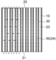
- Fig. 1A is a schematic diagram of the inlet end face and the outlet end face of a reactor according to one embodiment of the present invention.
- Fig. 1B is a schematic diagram of a cross section (a cross section parallel to the direction in which each cell extends) taken along line dd' in Fig. 1A.
- the arrows represent the flow of the process gas. Although only a portion of the process gas is represented by the arrows, the flow is the same in the portion not represented by the arrows.
- the reactor has an outer peripheral wall 10, and a porous partition wall 30 disposed inside the outer peripheral wall 10 and defining first cells 23 and second cells 24 extending from an inflow end face 20 to an outflow end face 21, and is equipped with a honeycomb structure in which the first cells 23 and the second cells 24 are adjacent to each other via the partition wall 30, and a pellet-shaped functional material 50 filled in the second cells 24.
- a treatment gas containing a target gas to be captured can flow through the first cells 23 and the second cells 24.
- FIG. 1A shows an example in which all of the first cells 23 and the second cells 24 are adjacent to each other via the partition wall 30, at least a portion of the first cells 23 and the second cells 24 may be adjacent to each other via the partition wall 30 (i.e., there may be a portion of the first cells 23 and the second cells 24 that is not adjacent to each other via the partition wall 30).
- the process gas flows in from the first cell 23 and the second cell 24 on the inlet end face 20 side.
- the second cell 24 is filled with a functional material 50, and the process gas can flow through the gaps between the filled functional material 50.
- a part of the process gas that flows into the first cell 23 flows into the second cell 24 through the porous partition wall 30.
- a part of the process gas that flows into the second cell 24 flows into the first cell 23 through the porous partition wall 30.
- the process gas that flows into the second cell 24 has the target gas to be captured recovered (e.g., adsorbed) by the functional material 50.
- the process gas that flows into the second cell 24 flows out from the outlet end face 21.
- the reactor may further include a second plugging portion 41 provided on the inlet end face 20 side and/or the outlet end face 21 side of the second cell 24.
- a second plugging portion 41 provided on the inlet end face 20 side and/or the outlet end face 21 side of the second cell 24.
- FIG. 2A is a schematic diagram of a cross section parallel to the extension direction of each cell of a reactor in which a second plugging portion 41 is provided on the outflow end face 21 side of a second cell 24 and the second plugging portion 41 is dense.
- the process gas flows in from the first cell 23 and the second cell 24 on the inlet end face 20 side.
- a part of the process gas that flows in the first cell 23 flows into the second cell 24 through the porous partition wall 30.
- a part of the process gas that flows into the second cell 24 flows into the first cell 23 through the porous partition wall 30.
- the target gas to be captured is recovered (e.g., adsorbed) by the functional material 50.
- the process gas from which the target gas to be captured has been recovered in the second cell 24 flows into the first cell 23 through the porous partition wall 30 and flows out from the outlet end face 21 of the first cell 23.
- the term "dense" means that the porosity is 10% or less, and the porosity may be 5% or less.
- FIG. 2B is a schematic diagram of a cross section parallel to the extension direction of each cell of a reactor in which a second plugging portion 41 is provided on the outflow end face 21 side of the second cell, and the second plugging portion 41 is porous.
- the second plugging portion 41 is porous, in addition to the flow of the process gas in the reactor shown in Fig. 2A, the process gas from which the target gas to be captured has been recovered in the second cells 24 flows out from the outflow end surface 21 of the second cells via the second plugging portion 41. Therefore, compared to the reactor shown in Fig. 2A, this reactor can increase the amount of target gas to be captured while suppressing pressure loss when the process gas is passed through.
- the term "porous" means that the porosity is 20% or more, and the porosity may be 30% or more.
- FIG. 3A is a schematic diagram of a cross section parallel to the extension direction of each cell of a reactor in which a second plugging portion 41 is provided on the inlet end face 20 side of the second cell 24 and the second plugging portion 41 is dense.
- the process gas flows in from the first cell 23 on the inlet end face 20 side.
- a part of the process gas that flows in the first cell 23 flows into the second cell 24 through the porous partition wall 30.
- the target gas to be captured is recovered (e.g., adsorbed) by the functional material 50.
- the process gas from which the target gas to be captured has been recovered in the second cell 24 flows out from the outlet end face 21 of the second cell 24, or flows into the first cell 23 through the porous partition wall 30 and flows out from the outlet end face 21 of the first cell 23.
- FIG. 3B is a schematic diagram of a cross section parallel to the extension direction of each cell of a reactor in which a second plugging portion 41 is provided on the inlet end face 20 side of the second cell 24, and the second plugging portion 41 is porous.
- the second plugging portions 41 are porous, and therefore, in addition to the flow of the process gas in the reactor shown in Fig. 3A, the process gas flows into the second cells 24 via the second plugging portions 41. Therefore, compared to the reactor shown in Fig. 3A, this reactor can increase the recovery amount of the target gas to be captured while suppressing the pressure loss when the process gas is circulated.
- FIG. 4A is a schematic diagram of a cross section parallel to the extension direction of each cell of a reactor in which second plugging portions 41 are provided on the inlet end face 20 side and the outlet end face 21 side of the second cell 24, the second plugging portions 41 on the inlet end face 20 side being dense, and the second plugging portions 41 on the outlet end face 21 side being dense.
- the process gas flows in from the first cell 23 on the inlet end face 20 side.
- a part of the process gas that flows into the first cell 23 flows into the second cell 24 through the porous partition wall 30.
- the target gas to be captured is recovered (e.g., adsorbed) by the functional material 50.
- the process gas from which the target gas to be captured has been recovered in the second cell 24 flows into the first cell 23 through the porous partition wall 30 and flows out from the outlet end face 21 of the first cell 23.
- FIG. 4B is a schematic diagram of a cross section parallel to the extension direction of each cell of a reactor in which second plugging portions 41 are provided on the inlet end face 20 side and the outlet end face 21 side of the second cell 24, the second plugging portions 41 on the inlet end face 20 side being dense and the second plugging portions 41 on the outlet end face 21 side being porous.
- the second plugging portion 41 on the outflow end face 21 side is porous, so in addition to the flow of the process gas in the reactor shown in Fig. 4A, the process gas flows out from the outflow end face 21 via the second plugging portion 41. Therefore, compared to the reactor shown in Fig. 4A, this reactor can increase the recovery amount of the target gas to be captured while suppressing the pressure loss when the process gas is circulated.
- the reactor may further include a first plugging portion 40 provided in the first cell 23 on the inlet end face 20 side.
- a first plugging portion 40 provided in the first cell 23 on the inlet end face 20 side.
- this reactor includes an outer peripheral wall 10, a porous partition wall 30 disposed inside the outer peripheral wall 10 and partitioning first cells 23 and second cells 24 extending from the inflow end face 20 to the outflow end face 21, a honeycomb structure having first plugging portions 40 provided in the first cells 23 on the inflow end face 20 side and second plugging portions 41 provided in the second cells 24 on the outflow end face 21 side, the first cells 23 and the second cells 24 being adjacent to each other via the partition wall 30, and a functional material 50 filled in the second cells 24.
- a treatment gas containing a target gas to be captured can flow through the first cells 23 and the second cells 24.
- FIG. 5D a partially enlarged view of the same cross section as in FIG. 5C is shown in FIG. 5D to explain the flow of the process gas.
- the length of each cell in the extending direction is shorter than that in FIG. 5C in order to make the explanation easier to understand.
- the arrows indicate the flow direction of the process gas.
- the process gas flows into the second cell 24 that does not have a plugging portion on the inlet end face 20 side.
- the second cell 24 is filled with a functional material 50, and the process gas can flow through the gaps between the filled functional material 50.
- the process gas that flows into the second cell 24 has the target gas to be captured recovered (e.g., adsorbed) by the functional material 50. Since the second plugging portion 41 is provided on the outlet end face 21 side of the second cell 24, the process gas that flows into the second cell 24 and from which the target gas to be captured is recovered flows into the first cell 23 through the porous partition wall 30. Then, the process gas that flows into the first cell 23 flows out from the outlet end face 21.
- FIGS. 6A and 6B show an example in which all the spaces between the first cells 23 and the second cells 24 are adjacent to each other via the partition wall 30, but at least a part of the spaces between the first cells 23 and the second cells 24 may be adjacent to each other via the partition wall 30 (i.e., there may be a part where the first cells 23 and the second cells 24 are not adjacent to each other via the partition wall 30).
- FIGS. 6A and 6B Schematic diagrams of the inlet end face and the outlet end face of a reactor of this type are shown in FIGS. 6A and 6B. Note that the cross sections of the lines bb' in FIGS. 6A and 6B are omitted because they are similar to the cross section of the line aa' in FIG. 5A.
- the first cell 23 and the second cell 24 are adjacent to each other in the direction of line bb' with the partition wall 30 interposed therebetween, while the first cell 23 and the second cell 24 are not adjacent to each other in the direction perpendicular to line bb' with the partition wall 30 interposed therebetween.
- the arrangement of the first cells 23 and the second cells 24 is not limited to the forms illustrated in Figures 5A to 5C and Figures 6A to 6B, and may be any arrangement as long as at least a portion of the space between the first cells 23 and the second cells 24 is adjacent to each other via a partition wall 30.
- the reactor may further include a first plugging portion 40 provided on the first cell 23 on the outflow end surface 21 side.
- a first plugging portion 40 provided on the first cell 23 on the outflow end surface 21 side.
- this reactor has a first plugging portion 40 provided on the first cell 23 on the outflow end face 21 side and a second plugging portion 41 provided on the second cell 24 on the inflow end face 20 side.
- the other structures can be the same as those of the above-mentioned reactor.
- a processing gas flows into the first cell 23 in which no plugging portion is provided on the inflow end face 20 side.
- the processing gas that flows into the first cell 23 flows into the second cell 24 through the porous partition wall 30 because the first plugging portion 40 is provided on the outflow end face 21 side.
- the processing gas that flows into the second cell 24 has the target gas to be captured recovered (for example, adsorbed) by the functional material 50. Then, the processing gas from which the target gas to be captured is recovered flows out from the outflow end face 21.
- the shape of the honeycomb structure is not particularly limited as long as it has the above structure.
- the outer shape of the cross section perpendicular to the direction in which the flow passages (first cells 23 and second cells 24) of the honeycomb structure extend can be a polygon such as a triangle, a square, a hexagon, or an octagon, a circle, an ellipse, an oval, an egg, an oval, a rounded square (each side and each corner is formed by a curve, the radius of curvature of each side is larger than the radius of curvature of each corner, and the whole is formed by a curve).
- the shape of the honeycomb structure is preferably a square shape (i.e., the shape of the honeycomb structure is a square prism).
- the end faces (the inflow end face 20 and the outflow end face 21) have the same shape as the cross section.
- the honeycomb structure has a square prism shape with the length of one side of the inlet end face 20 and the outlet end face 21 being 100 to 500 mm (preferably 200 to 400 mm) and the length in the direction in which the first cells 23 and the second cells 24 extend being 100 to 1000 mm (preferably 300 to 500 mm).
- a honeycomb structure of this size can ensure a sufficient filling amount of the functional material 50 in the second cells 24, ensuring practical use as a reactor.
- each cell is not particularly limited, but in a cross section perpendicular to the direction in which the flow path (first cell 23 and second cell 24) of the honeycomb structure extends, it can be a polygon such as a triangle, a square, a hexagon, or an octagon, or a round shape such as a circle, an ellipse, an oval, an egg, or an oblong.
- the shape of each cell may be a single shape or a combination of two or more types. Among these shapes of each cell, a triangle, a square, a hexagon, an octagon, or a combination thereof is preferable. By providing each cell with such a shape, it is possible to reduce the pressure loss when the processing gas flows.
- the shape of each cell in the cross section is the same as the shape of each cell at the end face (inlet end face 20 and outlet end face 21).
- Figures 8 to 13 are partial enlarged views of the inlet end faces of reactors equipped with cells having various shapes.
- the embodiment of Figure 8 has two different sized hexagonal cells: second hexagonal cell 24 is smaller than first hexagonal cell 23.
- the embodiment of FIG. 9 has hexagonal cells of equal size.
- 10 has two types of triangular cells with different sizes.
- the first cell 23 is composed of triangular cells of two sizes, and the smaller triangular cell is the same size as the second cell 24.
- 11 has an octagonal first cell 23 and an octagonal and rectangular second cell 24.
- the octagonal first cell 23 and the octagonal second cell 24 are the same size.
- 12 has three types of rectangular cells of different sizes.
- the size of the second cell 24 is smaller than the size of the first cell 23.
- the embodiment of Figure 13 has square and hexagonal cells.
- the first cells 23 are square cells of equal size.
- the second cells 24 are hexagonal cells. In any of the embodiments shown in FIGS. 8 to 13, the first cells 23 and the second cells 24 are arranged adjacent to each other with a partition wall 30 interposed therebetween.
- the first cells 23 are preferably arranged at positions facing the outer peripheral wall 10 .
- a schematic diagram of the inlet end face of a reactor having such a configuration is shown in FIG. 14A
- a schematic diagram of the outlet end face is shown in FIG. 14B
- a schematic diagram of the cross section taken along line cc' of FIGS. 14A and 14B is shown in FIG. 14C.
- this reactor is the same as the reactor shown in FIGS. 5A to 5C, except that the first cell 23 is disposed at a position facing the outer peripheral wall 10.
- the honeycomb structure may be a honeycomb bonded body having a plurality of honeycomb segments and a bonding layer that bonds the outer surfaces (the outer surfaces parallel to the direction in which the flow passages of the honeycomb segments extend) of the plurality of honeycomb segments together.
- the bonding layer can be formed using a bonding material.
- the bonding material is not particularly limited, but a ceramic material that has been made into a paste by adding a solvent such as water can be used.
- the bonding material may contain the same material as the outer peripheral wall 10 and the partition wall 30.
- the bonding material can also be used as an outer peripheral coating material after the honeycomb segments are bonded.
- the thickness of the partition wall 30 is not particularly limited, but from the viewpoints of ensuring the strength of the honeycomb structure and reducing the pressure loss when the treatment gas passes through the partition wall 30, it is preferably 0.05 mm to 5 mm, more preferably 0.10 mm to 4.5 mm, and even more preferably 0.15 mm to 4 mm.
- the "thickness of the partition wall 30" refers to the length of a line segment that crosses the partition wall 30 when the line segment connects the centers of gravity of adjacent cells in a cross section perpendicular to the extension direction of the flow paths (first cells 23 and second cells 24) of the honeycomb structure.
- the thickness of the partition wall 30 refers to the average value of the thicknesses of all the partition walls 30.
- the porosity of the partition walls 30 is not particularly limited, but from the viewpoints of ensuring the strength of the honeycomb structure and reducing the pressure loss when the treatment gas passes through the partition walls 30, it is preferably 30% or more and less than 80%, more preferably 35% to 75%, and even more preferably 40% to 70%.
- the "porosity of the partition walls 30" refers to the porosity of the partition walls 30 measured by mercury porosimetry in accordance with JIS R1655:2003.
- the average pore diameter of the partition walls 30 is not particularly limited, but from the viewpoints of ensuring the strength of the honeycomb structure and reducing the pressure loss when the treatment gas passes through the partition walls 30, it is preferably 10 ⁇ m to 300 ⁇ m, more preferably 15 ⁇ m to 280 ⁇ m, and even more preferably 20 ⁇ m to 260 ⁇ m.
- the "average pore diameter of the partition walls 30" means the pore diameter of the partition walls 30 at an integrated value of 50% in the pore distribution determined by mercury intrusion porosimetry in accordance with JIS R1655:2003.
- the thickness of the outer wall 10 is not particularly limited, but from the viewpoint of ensuring the strength of the honeycomb structure, it is preferably 0.05 mm to 10 mm, more preferably 0.20 mm to 8 mm, and even more preferably 0.30 mm to 6 mm.
- the thickness of the peripheral wall 10 refers to the length in the normal direction of the peripheral surface from the boundary between the peripheral wall 10 and the outermost cell or partition wall 30 to the peripheral surface of the honeycomb structure in a cross section perpendicular to the extension direction of the flow paths (first cells 23 and second cells 24) of the honeycomb structure.
- the cell density of the honeycomb structure is not particularly limited, but from the standpoint of ensuring the strength of the honeycomb structure and increasing the filling amount of functional material 50, it is preferably 0.05 cells/ cm2 to 25 cells/ cm2 , more preferably 0.1 cells/ cm2 to 20 cells/ cm2 , and even more preferably 0.5 cells/ cm2 to 15 cells/ cm2 .
- the term "cell density” refers to a value obtained by dividing the number of cells by the area of one end face of the honeycomb structure (the total area of the partition walls 30, the first cells 23 and the second cells 24 excluding the outer peripheral wall 10).
- the material of the outer peripheral wall 10 and the partition wall 30 is not particularly limited, but from the viewpoint of ensuring the strength of the honeycomb structure, it is preferable that the main component is one or more selected from cordierite, mullite, alumina, silicon carbide, and Si-bonded silicon carbide.
- the first plugging portion 40 is preferably dense, although not particularly limited thereto. This configuration allows the processing gas to flow easily through the distribution path as described above.
- the second plugging portion 41 is preferably, but not limited to, porous. With this configuration, as shown in Fig. 15, the process gas from which the target gas to be captured is collected by the functional material 50 also flows out from the outflow end surface 21 via the porous second plugging portion 41, so that the pressure loss during the flow of the process gas can be reduced.
- Fig. 15 is a partially enlarged view of the same cross section as Fig. 5D to explain the flow of the process gas.
- the treatment gas flows into the second cell 24 through the second plugging portion 41 provided on the inlet end face 20, so that the pressure loss when the treatment gas flows can be reduced.
- the material of the first plugging portion 40 and the second plugging portion 41 is not particularly limited and can be made of known materials such as ceramics, resin, etc., but it is preferable that they are made of resin from the viewpoints of production cost, productivity, etc.
- the characteristics of the first plugging portion 40 and the second plugging portion 41 can be ensured by appropriately selecting the type of material to be used. For example, when the first plugging portion 40 and the second plugging portion 41 are dense, a resin sheet, dense ceramics, glass, etc. may be selected and used, and it is preferable to select and use a resin sheet from the viewpoint of manufacturing cost, productivity, etc.
- the second plugging portion 41 is porous, a resin porous sheet, porous ceramics, glass, or the like may be selected and used, and it is preferable to select and use a resin porous sheet from the viewpoints of production cost, productivity, and the like.
- the functional material 50 is not particularly limited as long as it is capable of collecting the target gas contained in the processing gas, and for example, an adsorbent can be used.
- an adsorbent By using an adsorbent as the functional material 50, the target gas can be adsorbed and collected, and the collected target gas can be easily desorbed by changing conditions such as temperature.
- the term "adsorbent" refers to a material capable of attracting and storing the target gas to be captured contained in the treatment gas.
- the adsorbent is not particularly limited and may be appropriately selected depending on the type of gas to be captured.
- adsorbents effective for adsorbing the gas to be captured such as carbon dioxide (CO 2 )
- examples of adsorbents effective for adsorbing the gas to be captured include amine compounds, organometallic complexes, nanoporous ceramics or mesoporous silica carrying amine compounds and/or organometallic complexes, etc. These may be used alone or in combination of two or more.
- the amine compound is not particularly limited, but examples thereof include monoethanolamine (MEA) and N-methyldiethanolamine (MDEA).
- the organometallic complex is not particularly limited, but may be, for example, a porous metal-organic framework (MOF) having a structure capable of adsorbing the target gas to be captured in its pores.
- MOF porous metal-organic framework
- the functional material 50 has a pellet-like shape.
- pellet-like means a shape having a substantially constant thickness, such as a sphere, a cylinder, an elliptical cylinder, or a polygonal prism (e.g., a triangular prism, a quadrangular prism, a pentagonal prism, a hexagonal prism, etc.), and the cross section is a circle, an ellipse, a polygon, etc.
- pellet diameter The particle diameter of the pellet-like functional material 50 (hereinafter, sometimes referred to as "pellet diameter") is not particularly limited, but is, for example, 0.001 to 10 mm, preferably 0.1 to 10 mm, more preferably 0.5 to 10 mm, and even more preferably 1 to 10 mm.
- the pellet diameter means the average value of the minor axis and the major axis.
- a typical pellet-like functional material 50 is a sphere or a cylinder having a diameter or length of 0.3 to 10 mm.
- the particle size of the pellet-shaped functional material 50 is not particularly limited, it is preferable that the particle size is smaller on the outflow end face 21 side than on the center side in the extension direction of the second cells 24. With this configuration, the contact area of the functional material 50 on the outflow end face 21 side can be increased, making it easier to reliably collect the target gas to be captured contained in the process gas.
- the particle diameter of the pellet-shaped functional material 50 is determined by the following method: A microvideoscope manufactured by Keyence Corporation is used to measure the diameter of the smallest circle circumscribing the pellet-shaped functional material 50. This measurement is performed by randomly selecting 100 pellet-shaped functional material 50, and the average value is taken as the particle diameter of the pellet-shaped functional material 50.
- the particle diameter of the pellet-shaped functional material 50 is preferably larger on the outer wall 10 side than on the center in the direction perpendicular to the extension direction of the second cells 24.
- the processing gas flows easily in the center, while it is difficult for the processing gas to flow on the outer wall 10 side compared to the center. Therefore, by adopting the above-mentioned configuration, the processing gas is prevented from preferentially flowing into the second cells 24 in the center, and it becomes easier to flow the processing gas uniformly throughout the entire direction perpendicular to the extension direction of the second cells 24.
- the filling rate of the pellet-shaped functional material 50 in the second cell 24 is not particularly limited, but is preferably 20 to 70%. By controlling the filling rate to such a level, it is possible to increase the recovery efficiency of the target gas contained in the treatment gas.
- the filling rate can be measured, for example, by calculating the volume of the filled pellets by dividing the mass (kg) of the filled pellets by the density of the pellets (kg/ m3 ), dividing this by the volume ( m3 ) of the second cell 24, and multiplying by 100.
- the reactor according to the embodiment of the present invention may be arranged so that each cell extends horizontally, or may be arranged so that each cell extends vertically, with the inlet end surface 20 at the top and the outlet end surface 21 at the bottom.
- a reactor according to an embodiment of the present invention has an outer peripheral wall 10, and a porous partition wall 30 disposed inside the outer peripheral wall 10, through which a treatment gas containing a target gas to be captured can flow, and which partitions and forms first cells 23 and second cells 24 extending from an inflow end face 20 to an outflow end face 21, and can be manufactured by preparing a honeycomb structure in which the first cells 23 and the second cells 24 are adjacent to each other via the partition wall 30, and filling the second cells 24 with the functional material 50.
- the first plugging portions 40 and the second plugging portions 41 may be formed at an appropriate stage. As an example, a method for manufacturing the reactor shown in Figures 5A to 5D will be described.
- the method for manufacturing the reactor includes a step (step A) of preparing a honeycomb structure having an outer peripheral wall 10, a porous partition wall 30 that is disposed inside the outer peripheral wall 10 and that divides and forms first cells 23 and second cells 24 extending from an inflow end face 20 to an outflow end face 21 through which a treatment gas containing a gas to be captured can flow, the first cells 23 and the second cells 24 being adjacent to each other via the partition wall 30, a step (step B) of forming second plugging portions 41 on the outflow end face 21 side of the second cells 24, a step (step C) of filling the second cells 24 with a functional material 50, and a step (step D) of forming the first plugging portions 40 on the inflow end face 20 side of the first cells 23.
- steps having other structures can be manufactured in accordance with the manufacturing method of this reactor.
- the method for manufacturing the honeycomb structure is not particularly limited, and can be carried out in accordance with a method known in the art.
- the honeycomb structure can be manufactured as follows. First, a clay containing ceramic powder is extruded into a desired shape to produce a honeycomb molded body. At this time, by selecting a die and a jig of an appropriate shape, the shape and density of each cell, the shape and thickness of the partition wall 30 and the outer peripheral wall 10, etc. can be controlled.
- the ceramic powder the above-mentioned ceramic powder and raw material powder (for example, cordierite raw material) that becomes the above-mentioned ceramic after firing can be used.
- the cordierite raw material is a raw material that becomes cordierite by firing.
- the cordierite raw material preferably has a chemical composition of alumina (Al 2 O 3 ) (including aluminum hydroxide converted to alumina): 30 to 45 mass %, magnesia (MgO): 11 to 17 mass %, and silica (SiO 2 ): 42 to 57 mass %.
- the clay can contain a binder, a pore former, a dispersant, water, an organic solvent, etc.
- the porosity and average pore size of the partition walls 30 can be controlled by appropriately selecting the types and amounts of the ceramic powder, binder, pore-forming agent, and dispersing agent used.
- the honeycomb molded body obtained above is dried and fired to obtain a honeycomb structure.
- the drying method is not particularly limited, and a conventionally known drying method such as hot air drying, microwave drying, dielectric drying, reduced pressure drying, vacuum drying, freeze drying, etc. can be used. Among these, a drying method that combines hot air drying with microwave drying or dielectric drying is preferred because it can quickly and uniformly dry the entire honeycomb molded body.
- the second plugging portion 41 is formed on the outflow end face 21 side of the second cell 24 of the honeycomb structure obtained above.
- the method of forming each plugging portion is not particularly limited, and can be performed according to a conventional method.
- the second plugging portion 41 can be formed by attaching the resin sheet to the outflow end face 21 of the second cell 24.
- the second plugging portion 41 is made of ceramics, glass, or the like, first, a thin film having an opening corresponding to the second cell 24 of the outflow end face 21 of the honeycomb structure where the second plugging portion 41 is to be formed is attached.
- the outflow end face 21 of the honeycomb structure is immersed in a slurry plugging material (ceramics, glass, etc.), and the plugging material is allowed to enter the second cell 24 of the honeycomb structure that is not blocked by the thin film, thereby forming the second plugging portion 41.
- a slurry plugging material ceramics, glass, etc.
- step C the second cells 24 are filled with the functional material 50.
- the filling method is not particularly limited, and may be performed according to a conventional method.
- step D the first plugging portions 40 are formed on the inlet end face 20 side of the first cells 23.
- the method for forming the first plugging portions 40 may be performed in the same manner as the method for forming the second plugging portions 41 described above.
- the order of steps A to D is not particularly limited, except that step C is performed after step B. For example, steps B, C, and D may be performed in this order, or steps B, D, and C may be performed in this order, or steps D, B, and C may be performed in this order.
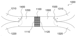
- FIG. 16 is a schematic diagram showing the configuration of a gas recovery device according to one embodiment of the present invention.
- the gas recovery device 1000 includes a reactor 1100, a gas supply pipe 1200 capable of supplying a treatment gas or a purge gas to an inlet 1110 of the reactor 1100, and a gas exhaust pipe 1300 capable of exhausting the treatment gas or the purge gas from an outlet 1120 of the reactor 1100.
- the reactor 1100 uses the above-mentioned reactor capable of increasing the amount of recovery of the target gas to be captured by increasing the amount of functional material 50 held while suppressing an increase in pressure loss. Therefore, the gas recovery device 1000 can also increase the amount of recovery of the target gas to be captured while suppressing an increase in pressure loss.
- the gas supply pipe 1200 has two branched gas supply pipes, a first gas supply branch pipe 1210 capable of supplying a process gas and a second gas supply branch pipe 1220 capable of supplying a purge gas.
- the gas exhaust pipe 1300 has a gas exhaust branch pipe that branches into two.
- the gas exhaust branch pipe can be a first gas exhaust branch pipe 1310 capable of exhausting a process gas, and a second gas exhaust branch pipe 1320 capable of exhausting a purge gas.
- the gas recovery device 1000 further includes a supply gas switching valve 1400 capable of blocking the first gas supply branch pipe 1210 or the second gas supply branch pipe 1220, and an exhaust gas switching valve 1500 capable of blocking the first gas exhaust branch pipe 1310 or the second gas exhaust branch pipe 1320.
- the supply gas switching valve 1400 when recovering the target gas contained in the treatment gas, the supply gas switching valve 1400 is switched to block the second gas supply branch pipe 1220 and open the first gas supply branch pipe 1210, and the exhaust gas switching valve 1500 is switched to block the second gas exhaust branch pipe 1320 and open the first gas exhaust branch pipe 1310.
- the treatment gas containing the target gas to be captured is supplied from the first gas supply branch pipe 1210 through the gas supply pipe 1200 to the inlet 1110 of the reactor 1100.
- the target gas to be captured is recovered from the treatment gas supplied to the reactor 1100 and discharged from the outlet 1120.
- the discharged treatment gas is discharged from the first gas exhaust branch pipe 1310 through the gas exhaust pipe 1300.
- the supply gas switching valve 1400 is switched to open the second gas supply branch pipe 1220 and block the first gas supply branch pipe 1210, and the exhaust gas switching valve 1500 is switched to open the second gas exhaust branch pipe 1320 and block the first gas exhaust branch pipe 1310.
- the purge gas is supplied to the inlet 1110 of the reactor 1100 from the second gas supply branch pipe 1220 via the gas supply pipe 1200.
- the purge gas supplied to the reactor 1100 is discharged from the outlet 1120 together with the target gas to be captured captured in the functional material 50 of the reactor 1100.
- the purge gas containing the target gas to be captured is discharged from the second gas exhaust branch pipe 1320 via the gas exhaust pipe 1300.
- the term "purge gas” refers to a gas that can desorb the target gas captured in the functional material 50 of the reactor 1100 and can be discharged from the reactor 1100.
- the purge gas may be appropriately selected depending on the type of target gas, but for example, when the target gas is carbon dioxide, water vapor or the like can be used.
- the water vapor is preferably at a high temperature of 100° C. or higher (for example, 120° C.).
- the gas recovery device 1000 may further include a heating mechanism capable of heating the reactor 1100.
- the purge gas at room temperature can be supplied from the second gas supply branch pipe 1220, and the purge gas can be heated to a predetermined temperature in the reactor 1100. Therefore, there is no need to preheat the purge gas supplied to the gas recovery device 1000.
- FIG. 17 is a schematic diagram showing the configuration of a gas recovery device according to another embodiment of the present invention.
- the gas recovery device 2000 has the same basic structure as the gas recovery device 1000 in Fig. 16. That is, the gas recovery device 2000 includes a reactor 1100, a gas supply pipe 1200 capable of supplying a processing gas or a purge gas to an inlet 1110 of the reactor 1100, and a gas exhaust pipe 1300 capable of exhausting the processing gas or the purge gas from an outlet 1120 of the reactor 1100. Therefore, the gas recovery device 2000 can also increase the amount of the target gas recovered while suppressing an increase in pressure loss.
- the gas supply pipe 1200 has two independent gas supply pipes: a first gas supply pipe 2100 capable of supplying a process gas, and a second gas supply pipe 2200 capable of supplying a purge gas.
- the gas exhaust pipe 1300 has two independent gas exhaust pipes: a first gas exhaust pipe 2300 capable of exhausting a process gas, and a second gas exhaust pipe 2400 capable of exhausting a purge gas.
- the reactor 1100 can be disposed between the first gas supply pipe 2100 and the first gas exhaust pipe 2300 or between the second gas supply pipe 2200 and the second gas exhaust pipe 2400 .
- the gas recovery device 2000 further includes a transfer mechanism (not shown) capable of transferring the reactor 1100 between the first gas supply pipe 2100 and the first gas exhaust pipe 2300 or between the second gas supply pipe 2200 and the second gas exhaust pipe 2400.
- the transfer mechanism is not particularly limited, and a known transfer mechanism (for example, a transfer mechanism having a motor drive) can be used.
- the reactor 1100 when recovering the gas to be captured contained in the treatment gas, the reactor 1100 is disposed between the first gas supply pipe 2100 and the first gas exhaust pipe 2300 by the transfer mechanism. Next, the treatment gas containing the gas to be captured is supplied from the first gas supply pipe 2100 to the inlet 1110 of the reactor 1100. The treatment gas supplied to the reactor 1100 has the gas to be captured recovered and is discharged from the outlet 1120. The discharged treatment gas is discharged from the first gas exhaust pipe 2300. Next, when the target gas to be captured collected in the reactor 1100 is to be desorbed, the reactor 1100 is disposed between the second gas supply pipe 2200 and the second gas exhaust pipe 2400 by a transfer mechanism.
- a purge gas is supplied from the second gas supply pipe 2200 to the inlet 1110 of the reactor 1100.
- the purge gas supplied to the reactor 1100 is discharged from the outlet 1120 together with the target gas to be captured captured in the functional material 50 of the reactor 1100.
- the purge gas containing the target gas to be captured is discharged from the second gas exhaust pipe 2400.
- the same purge gas as described above can be used.
- the gas recovery device 2000 may further include a heating mechanism capable of heating the reactor 1100 disposed between the second gas supply pipe 2200 and the second gas exhaust pipe 2400.
- FIG. 18 is a schematic diagram showing the configuration of a gas recovery system according to one embodiment of the present invention.
- the gas recovery system 3000 includes a gas recovery device 3100 , a gas releasing device 3200 , and a transfer device 3300 .
- the gas recovery device 3100 includes a detachable section 3110 that enables attachment and detachment of the reactor 1100, a gas supply pipe 1200 that can supply process gas to the inlet 1110 of the reactor 1100, and a gas exhaust pipe 1300 that can exhaust the process gas from the outlet 1120 of the reactor 1100.
- the gas release device 3200 includes a detachable section 3210 that can attach and detach the reactor 1100, a gas supply pipe 1200 that can supply purge gas to the inlet 1110 of the reactor 1100, and a gas exhaust pipe 1300 that can exhaust the purge gas from the outlet 1120 of the reactor 1100.
- the transfer device 3300 is capable of transferring the reactor 1100 from which the target gas to be captured has been recovered by the gas recovery device 3100 to the gas release device 3200, and of transferring the reactor 1100 from which the target gas to be captured has been released by the gas release device 3200 to the gas recovery device 3100.
- the reactor 1100 when recovering the target gas contained in the treatment gas, the reactor 1100 is placed in the attachment/detachment section 3110 of the gas recovery device 3100 by the transfer device 3300.
- the treatment gas containing the target gas is supplied from the gas supply pipe 1200 of the gas recovery device 3100 to the inlet 1110 of the reactor 1100.
- the target gas is recovered from the treatment gas supplied to the reactor 1100, and the treatment gas is discharged from the outlet 1120.
- the discharged treatment gas is discharged from the gas exhaust pipe 1300.
- the reactor 1100 arranged in the gas collection device 3100 is moved to the attachment/detachment section 3210 of the gas release device 3200 by the transfer device 3300.
- a purge gas is supplied from the gas supply pipe 1200 of the gas release device 3200 to the inlet 1110 of the reactor 1100.
- the purge gas supplied to the reactor 1100 is discharged from the outlet 1120 together with the target gas to be captured in the functional material 50 of the reactor 1100.
- the purge gas containing the target gas to be captured is discharged from the gas exhaust pipe 1300.
- the same purge gas as described above can be used.
- the gas release device 3200 may further include a heating mechanism capable of heating the reactor 1100.
- the purge gas can be supplied at room temperature from the gas supply pipe 1200 and heated to a predetermined temperature in the reactor 1100. Therefore, it is not necessary to preheat the purge gas supplied to the gas release device 3200.
- the transfer device 3300 may include, but is not limited to, a vehicle. With this configuration, the reactor 1100 can be transported efficiently even if the gas recovery device 3100 and the gas release device 3200 are located apart.
Landscapes
- Chemical & Material Sciences (AREA)
- Engineering & Computer Science (AREA)
- Analytical Chemistry (AREA)
- General Chemical & Material Sciences (AREA)
- Oil, Petroleum & Natural Gas (AREA)
- Chemical Kinetics & Catalysis (AREA)
- Physical Or Chemical Processes And Apparatus (AREA)
Priority Applications (5)
| Application Number | Priority Date | Filing Date | Title |
|---|---|---|---|
| CN202380081399.8A CN120322285A (zh) | 2022-12-20 | 2023-12-20 | 反应器、气体回收装置以及气体回收系统 |
| JP2024566115A JPWO2024135747A1 (https=) | 2022-12-20 | 2023-12-20 | |
| EP23907107.9A EP4640296A1 (en) | 2022-12-20 | 2023-12-20 | Reactor, gas recovery device, and gas recovery system |
| AU2023410194A AU2023410194A1 (en) | 2022-12-20 | 2023-12-20 | Reactor, gas recovery device, and gas recovery system |
| US19/214,137 US20250276268A1 (en) | 2022-12-20 | 2025-05-21 | Reactor, gas recovery device, and gas recovery system |
Applications Claiming Priority (2)
| Application Number | Priority Date | Filing Date | Title |
|---|---|---|---|
| JPPCT/JP2022/046959 | 2022-12-20 | ||
| JP2022046959 | 2022-12-20 |
Related Child Applications (1)
| Application Number | Title | Priority Date | Filing Date |
|---|---|---|---|
| US19/214,137 Continuation US20250276268A1 (en) | 2022-12-20 | 2025-05-21 | Reactor, gas recovery device, and gas recovery system |
Publications (1)
| Publication Number | Publication Date |
|---|---|
| WO2024135747A1 true WO2024135747A1 (ja) | 2024-06-27 |
Family
ID=91588726
Family Applications (1)
| Application Number | Title | Priority Date | Filing Date |
|---|---|---|---|
| PCT/JP2023/045788 Ceased WO2024135747A1 (ja) | 2022-12-20 | 2023-12-20 | 反応器、ガス回収装置、並びにガス回収システム |
Country Status (6)
| Country | Link |
|---|---|
| US (1) | US20250276268A1 (https=) |
| EP (1) | EP4640296A1 (https=) |
| JP (1) | JPWO2024135747A1 (https=) |
| CN (1) | CN120322285A (https=) |
| AU (1) | AU2023410194A1 (https=) |
| WO (1) | WO2024135747A1 (https=) |
Citations (9)
| Publication number | Priority date | Publication date | Assignee | Title |
|---|---|---|---|---|
| JPH06182219A (ja) * | 1992-08-05 | 1994-07-05 | Corning Inc | ガス混合物の変性装置及び方法 |
| JPH07204442A (ja) * | 1994-01-26 | 1995-08-08 | Matsushita Electric Works Ltd | ハニカム脱臭材 |
| JP2004041277A (ja) * | 2002-07-09 | 2004-02-12 | Mitsubishi Paper Mills Ltd | 脱臭フィルター |
| JP2006026523A (ja) * | 2004-07-15 | 2006-02-02 | Fuji Silysia Chemical Ltd | 吸着器、および冷房装置 |
| US20160038915A1 (en) * | 2014-08-11 | 2016-02-11 | Corning Incorporated | Method of making a honeycomb having channels containing a porous adsorbent |
| JP2017000930A (ja) * | 2015-06-08 | 2017-01-05 | イビデン株式会社 | ハニカムフィルタ |
| JP2018039683A (ja) * | 2016-09-05 | 2018-03-15 | 東京窯業株式会社 | 水素製造方法及び水素製造装置 |
| JP2021187717A (ja) * | 2020-06-02 | 2021-12-13 | イビデン株式会社 | ハニカム構造体及びガス回収装置 |
| JP2022170972A (ja) * | 2021-04-30 | 2022-11-11 | トヨタ自動車株式会社 | 排ガス浄化装置 |
-
2023
- 2023-12-20 AU AU2023410194A patent/AU2023410194A1/en active Pending
- 2023-12-20 EP EP23907107.9A patent/EP4640296A1/en active Pending
- 2023-12-20 CN CN202380081399.8A patent/CN120322285A/zh active Pending
- 2023-12-20 WO PCT/JP2023/045788 patent/WO2024135747A1/ja not_active Ceased
- 2023-12-20 JP JP2024566115A patent/JPWO2024135747A1/ja active Pending
-
2025
- 2025-05-21 US US19/214,137 patent/US20250276268A1/en active Pending
Patent Citations (9)
| Publication number | Priority date | Publication date | Assignee | Title |
|---|---|---|---|---|
| JPH06182219A (ja) * | 1992-08-05 | 1994-07-05 | Corning Inc | ガス混合物の変性装置及び方法 |
| JPH07204442A (ja) * | 1994-01-26 | 1995-08-08 | Matsushita Electric Works Ltd | ハニカム脱臭材 |
| JP2004041277A (ja) * | 2002-07-09 | 2004-02-12 | Mitsubishi Paper Mills Ltd | 脱臭フィルター |
| JP2006026523A (ja) * | 2004-07-15 | 2006-02-02 | Fuji Silysia Chemical Ltd | 吸着器、および冷房装置 |
| US20160038915A1 (en) * | 2014-08-11 | 2016-02-11 | Corning Incorporated | Method of making a honeycomb having channels containing a porous adsorbent |
| JP2017000930A (ja) * | 2015-06-08 | 2017-01-05 | イビデン株式会社 | ハニカムフィルタ |
| JP2018039683A (ja) * | 2016-09-05 | 2018-03-15 | 東京窯業株式会社 | 水素製造方法及び水素製造装置 |
| JP2021187717A (ja) * | 2020-06-02 | 2021-12-13 | イビデン株式会社 | ハニカム構造体及びガス回収装置 |
| JP2022170972A (ja) * | 2021-04-30 | 2022-11-11 | トヨタ自動車株式会社 | 排ガス浄化装置 |
Non-Patent Citations (2)
| Title |
|---|
| "Cost and Evaluation of Direct Air Capture (DAC) Method for Carbon Dioxide", vol. 2, March 2021, CENTER FOR LOW CARBON SOCIETY STRATEGY, article "Adsorption Separation Process" |
| See also references of EP4640296A1 |
Also Published As
| Publication number | Publication date |
|---|---|
| AU2023410194A1 (en) | 2025-06-19 |
| CN120322285A (zh) | 2025-07-15 |
| US20250276268A1 (en) | 2025-09-04 |
| JPWO2024135747A1 (https=) | 2024-06-27 |
| EP4640296A1 (en) | 2025-10-29 |
Similar Documents
| Publication | Publication Date | Title |
|---|---|---|
| AU2008254961B2 (en) | Temperature swing adsorption of CO2 from flue gas utilizing heat from compression | |
| US20250281869A1 (en) | Reactor and method for producing same, gas recovery device, and gas recovery system | |
| US20070072769A1 (en) | Carbon dioxide absorbent and carbon dioxide separation apparatus | |
| TW202417100A (zh) | 酸性氣體吸附裝置 | |
| WO2024135747A1 (ja) | 反応器、ガス回収装置、並びにガス回収システム | |
| US20260001030A1 (en) | Reactor and gas recovery device | |
| US20250387746A1 (en) | Reactor and gas recovery device | |
| US20250387744A1 (en) | Reactor and gas recovery device | |
| WO2025254039A1 (ja) | 吸着構造体及びガス回収装置 | |
| WO2026009523A1 (ja) | ガス回収装置 | |
| WO2025141666A1 (ja) | 反応器及びガス回収装置 | |
| WO2024048566A1 (ja) | 酸性ガスの回収方法 | |
| WO2025258401A1 (ja) | ハニカム構造体及びガス回収装置 | |
| WO2025253715A1 (ja) | 反応器 | |
| US20260048383A1 (en) | Honeycomb structure supporting co2 adsorbent, method for manufacturing same, and method for recovering co2 | |
| WO2024214570A1 (ja) | 酸性ガス回収システムおよび酸性ガスの回収方法 | |
| WO2024214571A1 (ja) | 酸性ガス回収システムおよび酸性ガスの回収方法 | |
| JP2025131173A (ja) | ハニカム構造体及び直接空気回収装置 | |
| CN121063486A (zh) | 一种半导体封装测试系统中氢气纯化方法及系统 |
Legal Events
| Date | Code | Title | Description |
|---|---|---|---|
| 121 | Ep: the epo has been informed by wipo that ep was designated in this application |
Ref document number: 23907107 Country of ref document: EP Kind code of ref document: A1 |
|
| WWE | Wipo information: entry into national phase |
Ref document number: 2024566115 Country of ref document: JP |
|
| WWE | Wipo information: entry into national phase |
Ref document number: 202380081399.8 Country of ref document: CN |
|
| WWE | Wipo information: entry into national phase |
Ref document number: AU2023410194 Country of ref document: AU |
|
| ENP | Entry into the national phase |
Ref document number: 2023410194 Country of ref document: AU Date of ref document: 20231220 Kind code of ref document: A |
|
| WWP | Wipo information: published in national office |
Ref document number: 202380081399.8 Country of ref document: CN |
|
| WWE | Wipo information: entry into national phase |
Ref document number: 2023907107 Country of ref document: EP |
|
| NENP | Non-entry into the national phase |
Ref country code: DE |
|
| ENP | Entry into the national phase |
Ref document number: 2023907107 Country of ref document: EP Effective date: 20250721 |
|
| ENP | Entry into the national phase |
Ref document number: 2023907107 Country of ref document: EP Effective date: 20250721 |
|
| ENP | Entry into the national phase |
Ref document number: 2023907107 Country of ref document: EP Effective date: 20250721 |
|
| WWP | Wipo information: published in national office |
Ref document number: 2023907107 Country of ref document: EP |