WO2024135461A1 - 不織布シート及び吸収性物品 - Google Patents
不織布シート及び吸収性物品 Download PDFInfo
- Publication number
- WO2024135461A1 WO2024135461A1 PCT/JP2023/044463 JP2023044463W WO2024135461A1 WO 2024135461 A1 WO2024135461 A1 WO 2024135461A1 JP 2023044463 W JP2023044463 W JP 2023044463W WO 2024135461 A1 WO2024135461 A1 WO 2024135461A1
- Authority
- WO
- WIPO (PCT)
- Prior art keywords
- nonwoven fabric
- fabric sheet
- fibers
- skin side
- side layer
- Prior art date
- Legal status (The legal status is an assumption and is not a legal conclusion. Google has not performed a legal analysis and makes no representation as to the accuracy of the status listed.)
- Ceased
Links
Images


Classifications
-
- A—HUMAN NECESSITIES
- A61—MEDICAL OR VETERINARY SCIENCE; HYGIENE
- A61F—FILTERS IMPLANTABLE INTO BLOOD VESSELS; PROSTHESES; DEVICES PROVIDING PATENCY TO, OR PREVENTING COLLAPSING OF, TUBULAR STRUCTURES OF THE BODY, e.g. STENTS; ORTHOPAEDIC, NURSING OR CONTRACEPTIVE DEVICES; FOMENTATION; TREATMENT OR PROTECTION OF EYES OR EARS; BANDAGES, DRESSINGS OR ABSORBENT PADS; FIRST-AID KITS
- A61F13/00—Bandages or dressings; Absorbent pads
- A61F13/15—Absorbent pads, e.g. sanitary towels, swabs or tampons for external or internal application to the body; Supporting or fastening means therefor; Tampon applicators
- A61F13/51—Absorbent pads, e.g. sanitary towels, swabs or tampons for external or internal application to the body; Supporting or fastening means therefor; Tampon applicators characterised by the outer layers of the pads
- A61F13/511—Topsheet, i.e. the permeable cover or layer facing the skin
-
- D—TEXTILES; PAPER
- D04—BRAIDING; LACE-MAKING; KNITTING; TRIMMINGS; NON-WOVEN FABRICS
- D04H—MAKING TEXTILE FABRICS, e.g. FROM FIBRES OR FILAMENTARY MATERIAL; FABRICS MADE BY SUCH PROCESSES OR APPARATUS, e.g. FELTS, NON-WOVEN FABRICS; COTTON-WOOL; WADDING ; NON-WOVEN FABRICS FROM STAPLE FIBRES, FILAMENTS OR YARNS, BONDED WITH AT LEAST ONE WEB-LIKE MATERIAL DURING THEIR CONSOLIDATION
- D04H1/00—Non-woven fabrics formed wholly or mainly of staple fibres or like relatively short fibres
- D04H1/40—Non-woven fabrics formed wholly or mainly of staple fibres or like relatively short fibres from fleeces or layers composed of fibres without existing or potential cohesive properties
- D04H1/42—Non-woven fabrics formed wholly or mainly of staple fibres or like relatively short fibres from fleeces or layers composed of fibres without existing or potential cohesive properties characterised by the use of certain kinds of fibres insofar as this use has no preponderant influence on the consolidation of the fleece
- D04H1/4391—Non-woven fabrics formed wholly or mainly of staple fibres or like relatively short fibres from fleeces or layers composed of fibres without existing or potential cohesive properties characterised by the use of certain kinds of fibres insofar as this use has no preponderant influence on the consolidation of the fleece characterised by the shape of the fibres
Definitions
- the present invention relates to a nonwoven fabric sheet and an absorbent article.
- Patent Document 1 discloses a sanitary napkin having a top sheet arranged on the skin contact side, a back sheet arranged on the non-skin contact side, and an absorbent body arranged between the top sheet and the back sheet.
- the absorbent body in Patent Document 1 is made of pulp fibers, etc.
- the present invention was made in consideration of the above problems, and its purpose is to provide a nonwoven fabric sheet for use in absorbent articles that allows absorbed liquid to easily diffuse within the nonwoven fabric sheet.
- the main invention for achieving the above-mentioned object is a nonwoven fabric sheet for use in absorbent articles, comprising a plurality of fibers having latent crimp fibers, a linear high density portion in which the density of the fibers is higher than the surrounding area, the high density portion being thinner than the surrounding area, and the plurality of fibers not fused to each other.
- the present invention provides a nonwoven fabric sheet for use in absorbent articles that allows absorbed liquid to easily diffuse within the nonwoven fabric sheet.
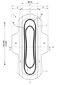
- FIG. 2 is a plan view of the sanitary napkin 1 as seen from the skin side. 2 is a schematic cross-sectional view taken along the line AA in FIG. 1.
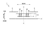
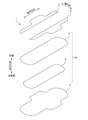
- 1A and 1B are diagrams illustrating the configuration of a napkin 1.
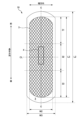
- 1 is a diagram illustrating an absorbent layer 10 of a napkin 1.
- FIG. Fig. 5A is a diagram showing a schematic cross section of the skin side layer 2.
- Fig. 5B is a diagram showing a schematic cross section of the non-skin side layer 3.
- FIG. 5 is an enlarged view of a portion X in FIG. 4 .
- 7 is a schematic cross-sectional view taken along the line BB in FIG. 6.
- the nonwoven fabric sheet used in absorbent articles has a plurality of fibers having latent crimp fibers, and has a linear high density portion in which the density of the fibers is higher than the surrounding area, the high density portion being thinner than the surrounding area, and the plurality of fibers are not fused to each other.
- the fibers While fused fibers tend to hinder the diffusion of liquid, the narrower the gaps between the fibers, the easier it is for liquid to diffuse due to capillary action.
- the fibers are not fused, which reduces the risk of the diffusion of absorbed liquid being hindered compared to when the fibers are fused, and reduces the risk that the latent crimped fibers will absorb liquid and swell like pulp fibers, making it easier to maintain the gaps between the fibers.
- the gaps between the fibers are narrowed due to the crimping of the latent crimped fibers, and the high density parts further narrow the gaps between the fibers, making it easier for absorbed liquid to diffuse within the nonwoven fabric sheet due to capillary action.
- the nonwoven fabric sheet of embodiment 2 allows absorbed liquid to be easily dispersed within the nonwoven fabric sheet, reducing the localized retention of absorbed excrement, thereby reducing leakage of excrement and discomfort felt by the wearer.
- a nonwoven fabric sheet according to aspect 1 or 2 which has a longitudinal direction, a width direction, and a thickness direction, the length of the nonwoven fabric sheet in the longitudinal direction is longer than the length in the width direction, the high density portions are surrounded by low density portions having a lower fiber density than the high density portions, and the low density portions are adjacent to both sides of the high density portions in the longitudinal direction.
- liquid absorbed in the low-density portion on one side in the longitudinal direction is easily transferred to the high-density portion by capillary action, and any excess liquid that is absorbed in the high-density portion is absorbed in the low-density portion located on the other side in the longitudinal direction, which makes it easier to promote the diffusion of liquid in the longitudinal direction of the nonwoven fabric sheet.
- the nonwoven fabric sheet of embodiment 4 makes it easier to diffuse absorbed liquid in the longitudinal direction of the nonwoven fabric sheet.
- the nonwoven fabric sheet of aspect 5 makes it easier to promote the diffusion of liquid in the longitudinal direction in the central region.
- Aspect 6 The nonwoven fabric sheet according to any one of aspects 1 to 5, wherein an average distance between the fibers is 5 ⁇ m or more and 30 ⁇ m or less.
- the nonwoven fabric sheet of embodiment 6 prevents the diffusion of liquid from being hindered by the fusion of fibers, while providing a flow path for diffusing liquid and an area for retaining liquid more than when the average distance between fibers is less than 5 ⁇ m, and is more likely to promote the drawing in and absorption of absorbed liquid by capillary action more than when the average distance between fibers is greater than 30 ⁇ m.
- Aspect 7 The nonwoven fabric sheet according to any one of aspects 1 to 6, wherein the high density portion forms a recess having a bottom.
- the nonwoven fabric sheet of aspect 7 makes it easier to diffuse absorbed liquid within the nonwoven fabric sheet even when a bottomed recess is formed.
- the nonwoven fabric sheet of aspect 8 allows the nonwoven fabric sheet to absorb liquid more easily than when the fiber basis weight of the nonwoven fabric sheet is less than 80 gsm, and reduces the risk of the nonwoven fabric sheet becoming excessively thick or stiff compared to when the fiber basis weight of the nonwoven fabric sheet is greater than 350 gsm.
- the nonwoven fabric sheet of aspect 9 makes it easier for the nonwoven fabric sheet to diffuse excrement when it absorbs it, reducing discomfort caused by excrement leaking or localized retention.
- the nonwoven fabric sheet of any one of aspects 1 to 9 is an absorbent article having a thickness direction and a skin-side sheet provided on the skin side of the nonwoven fabric sheet, the skin-side sheet having a first void formed by a plurality of fibers, the nonwoven fabric sheet having a second void formed by the plurality of fibers, and the proportion of the second void of the nonwoven fabric sheet in a void ratio evaluation test for quantitatively evaluating the proportion of the voids in a specified area is smaller than the proportion of the first void of the skin-side sheet in the void ratio evaluation test.
- the liquid absorbed by the skin-side sheet is easily diffused into the nonwoven fabric sheet by capillary action, making it easier to reduce the amount of liquid remaining on the skin-side sheet, and reducing the discomfort caused by excrement coming into contact with the wearer's skin.
- the absorbent article is a nonwoven fabric sheet described in any one of aspects 1 to 10, which has a longitudinal direction, a width direction, and a thickness direction, the longitudinal length of the nonwoven fabric sheet is longer than the width direction length, has a skin-side sheet provided on the skin side of the nonwoven fabric sheet, and no adhesive is provided between the nonwoven fabric sheet and the skin-side sheet in the central portion of the width direction.
- the nonwoven fabric sheet of embodiment 11 can reduce the risk of the adhesive interfering with the absorption of liquid.
- the absorbent article according to the present invention will be described taking a sanitary napkin 1 (hereinafter also referred to as "napkin 1") as an example of the absorbent article according to the present invention.
- the absorbent article according to the present invention may be a pants-type disposable diaper or a tape-type disposable diaper for adults or infants, sanitary shorts, sanitary napkin, light incontinence pad, absorbent pad, disposable diaper or absorbent sheet for animals, drip sheet, etc.
- the "wearing state” in the following embodiment becomes a "use state” and the wearer becomes a "user, etc.”
- the wearing state is also referred to as a "use state” and the wearer is also referred to as a "user, etc.”
- FIG. 1 is a plan view of a sanitary napkin 1 (hereinafter also referred to as "napkin") as seen from the skin side.
- FIG. 2 is a schematic cross-sectional view of the napkin 1 taken along the line A-A.
- FIG. 3 is a diagram for explaining the configuration of the napkin 1.
- the napkin 1 has a longitudinal direction, a width direction, and a thickness direction which are perpendicular to one another. In the thickness direction, the side that contacts the wearer's skin is the skin side, and the opposite side is the non-skin side.
- the skin side in the thickness direction is the side that receives excrement (liquid) when worn, and is also referred to as the "absorbent side".
- the non-skin side in the thickness direction is the side opposite to the absorbent side, and is also referred to as the "non-absorbent side".
- the center line C-C shown in FIG. 1 etc. indicates the center (central position) of the napkin 1 in the width direction.
- the napkin 1 has a skin-side layer (nonwoven fabric sheet) 2, a non-skin-side layer (nonwoven fabric sheet) 3, a back sheet 4, and a side sheet 5. As shown in FIG. 3 etc., the napkin 1 is layered in the thickness direction in the following order from the skin side: side sheet 5, skin-side layer 2, non-skin-side layer 3, and back sheet 4. Each member layered in the thickness direction is fixed together with an adhesive such as a hot melt adhesive.
- the skin-side layer 2 is the skin-side sheet located closest to the skin in the widthwise center of the napkin 1, and is an absorbent member that abuts against the excretory opening when worn and receives excrement discharged from the excretory opening.
- the skin-side layer 2 is substantially rectangular in shape and is long in the longitudinal direction, with the longitudinal length L2 being longer than the widthwise length W2.
- the non-skin side layer 3 is a non-skin side sheet provided between the skin side layer 2 and the back sheet 4 in the thickness direction, and the non-skin side layer 3 is slightly smaller than the skin side layer 2 in a plan view.
- the non-skin side layer 3 is substantially rectangular in shape and is long in the longitudinal direction, and the longitudinal length L3 is longer than the widthwise length W3.
- the non-skin side layer 3 is an absorbent member that absorbs the excrement absorbed by the skin side layer 2 and retains the excrement.
- the non-skin side layer 3 By providing the non-skin side layer 3 at the crotch position of the wearer when the napkin 1 is worn, when the napkin 1 absorbs excrement, the non-skin side layer 3 can absorb the excrement and disperse the excrement within the non-skin side layer 3. This can reduce discomfort to the wearer caused by excrement leaking from the napkin 1 or excrement remaining locally on the surface of the skin side layer 2, etc.
- the skin-side layer 2 and the non-skin-side layer 3 are nonwoven fabrics (nonwoven fabric sheets) made of latent crimped fibers 2f and latent crimped fibers 3f (see FIG. 5), respectively.
- the skin-side layer 2 and the non-skin-side layer 3 are nonwoven fabrics made of only latent crimped fibers (100% latent crimped fibers).
- the layers (nonwoven fabrics) making up the skin-side layer 2 and the non-skin-side layer 3 may use, in addition to latent crimped fibers, fibers made of polyolefins such as polyethylene (PE) and polypropylene (PP), polyesters (PET and PBT), polyamides, etc., and composite fibers of these, as well as hydrophilic fibers such as rayon, pulp, and cotton.
- latent crimped fibers 2f and the latent crimped fibers 3f are also simply referred to as “fibers 2f” and "fibers 3f.”
- Nonwoven fabric refers to a fiber sheet, web, or batt in which the fibers are oriented in one direction or randomly and are bonded by entanglement and/or fusion and/or adhesion (JIS L0222:2001 Nonwoven fabric terminology 101).
- nonwoven fabric is a cloth in which the fibers are integrated without being woven, and is a sheet with a breaking strength of 5 [N]/25 mm or more.
- the breaking strength can be measured by a well-known method, for example, by the following method.
- a tensile tester Shiadzu Corporation: Autograph, AGS-1kNG equipped with a load cell with a maximum load capacity of 50 N is used.
- one chuck grips the tip of one side of the nonwoven fabric sheet in the longitudinal or transverse direction, and the other chuck grips the other side of the nonwoven fabric sheet.
- the two chucks are pulled at a constant speed (e.g., 100 mm/min) so that the distance between them increases, while the load applied to the two chucks is measured.
- the load at which the nonwoven fabric sheet breaks is the breaking strength.
- nonwoven fabrics include nonwoven fabrics obtained by the meltblown method (meltblown nonwoven fabric), nonwoven fabrics obtained by the electrospinning method (electrospinning nonwoven fabric), nonwoven fabrics obtained by the spunbond method (spunbond nonwoven fabric), nonwoven fabrics produced by the air-through method (air-through nonwoven fabric), nonwoven fabrics produced by the spunlace method (spunlace nonwoven fabric), nonwoven fabrics produced by the needlepunch method (needlepunch nonwoven fabric), or laminates of two or more of these nonwoven fabrics, or laminates of these nonwoven fabrics with other nonwoven fabrics or other materials.
- the skin-side layer 2 and the non-skin-side layer 3 of this embodiment are each a spunlace nonwoven fabric in which no adhesive is used and the fibers are entangled by a water flow.
- the nonwoven fabric sheet of the skin side layer 2 of the napkin 1 of this embodiment is formed by the spunlace method as described below.
- the hydrophilic fibers 2fb are treated with a carding machine or the like to form a non-skin side fiber web having a form such as a carded web.
- the hydrophobic fibers 2fa are processed using a carding machine or the like to produce a skin-side fiber web having the form of a carded web or the like, which is then fed onto the non-skin-side fiber web while the non-skin-side fiber web is being transported, and laminated to obtain a laminated web.
- a high-pressure water jet treatment such as a water jet is applied to the skin side of the laminated web to entangle the fibers between the fiber layers and the fibers of each web, thereby obtaining a laminate.
- the laminate is placed in a dryer and heated to a temperature at which the latent crimpable fibers can shrink, thereby obtaining an integrated nonwoven fabric sheet (skin side layer 2).
- This nonwoven fabric sheet has voids formed by the plurality of fibers 2f.
- the nonwoven fabric sheet of the non-skin side layer 3 of the napkin 1 of this embodiment is formed in the same manner as the nonwoven fabric sheet of the skin side layer 2.
- the nonwoven fabric sheet of the non-skin side layer 3 differs from the skin side layer 2 in that it does not use hydrophobic fibers and is made by laminating only a web of hydrophilic fibers.
- Latently crimpable fibers 2f and 3f are fibers that shrink when heated to develop a helical shape.
- latent crimpable fibers 2f and 3f include side-by-side composite fibers in which high and low shrinkage components are arranged in parallel, and eccentric core-sheath composite fibers in which the high shrinkage component is the core and the low shrinkage component is the sheath, with the centers of gravity of both components not overlapping at a single point.
- the latent crimpable fiber shrinks, for example, into a coil shape.
- any combination of resins with different thermal shrinkage rates or thermal expansion rates can be used without any particular limitations, and may be a combination of the same or a single resin, or a combination of different resins.
- Specific examples of combinations of resins with different thermal shrinkage rates or thermal expansion rates that form the latent shrinkage fibers include combinations of polyester resins and combinations of polyamide resins.
- the nonwoven fabric of the skin side layer 2 and the non-skin side layer 3 of this embodiment is a combination of polyester resins (single component resins), specifically, a latent shrink fiber of a combination of polyethylene terephthalate (PET) and modified PET is used.
- the modified PET is a PET modified by copolymerizing ethylene glycol and terephthalic acid, which are the components of PET, with a diol component other than ethylene glycol or a dicarboxylic acid component other than terephthalic acid as a minor component.
- diol components other than ethylene glycol include, for example, 1,3-propanediol, 1,4-butanediol, 1,6-hexanediol, neopentyl glycol, 3-methyl-1,5-pentanediol, cyclohexanedimethanol, diethylene glycol, triethylene glycol, polyethylene glycol, polytetramethylene glycol, etc.
- dicarboxylic acid components other than terephthalic acid include, for example, isophthalic acid, phthalic acid, naphthalenedicarboxylic acid, cyclohexanedicarboxylic acid, adipic acid, sebacic acid, etc.
- a web made of latently crimpable fibers of a combination of PET and modified PET is formed using a web forming means such as a carding machine, the fibers of this web are entangled by the spunlace method to form a nonwoven fabric, and this is heated to a predetermined temperature to cause the latently crimpable fibers to crimp, thereby producing the nonwoven fabrics of the skin side layer 2 and the non-skin side layer 3.
- the basis weight of the latently crimped fibers in the nonwoven fabric after heating is greater than the basis weight of the latently crimpable fibers in the nonwoven fabric before heating.
- the nonwoven fabric shrinks due to the crimping of the latently crimpable fibers, and the basis weight of the fibers increases.
- the skin-side layer 2 and non-skin-side layer 3 are each an absorbent layer 10 of a predetermined thickness that is liquid-permeable and has the ability to absorb and retain liquid.
- Figure 4 is a diagram explaining the absorbent layer 10 of the napkin 1.
- the skin-side layer 2 is a skin-side sheet that contacts the wearer's skin, and is a member that first receives excrement when worn, absorbing the received excrement within the skin-side layer 2 and allowing it to permeate towards the non-skin side.
- the non-skin-side layer 3 is a member that absorbs and retains the excrement that permeates from the skin-side layer 2.
- the skin side layer 2 and the non-skin side layer 3 each have a void formed by a plurality of fibers (latently crimped fibers) 2f, 3f.
- FIG. 5A is a schematic diagram of the cross section of the skin side layer 2
- FIG. 5B is a schematic diagram of the cross section of the non-skin side layer 3, and the dimensions are not necessarily accurate.
- the voids in the skin side layer 2 and the non-skin side layer 3 may be voids between discontinuous fibers (a plurality of fibers), voids formed by a single continuous fiber being curved or spiral, or voids formed by a combination of these.
- the voids formed by a plurality of fibers 2f, 3f refer to spaces/areas in the skin side layer 2 and the non-skin side layer 3 where a plurality of fibers 2f, 3f are not provided.
- the voids may be not only spaces surrounded by the fibers 2f, 3f or spaces closed by the fibers, but also spaces that are at least partially open in the voids formed by the fibers 2f, 3f.
- the skin-side layer 2 and the non-skin-side layer 3 each contain latent crimped fibers 2f and 3f, and as a result of the crimping of the fibers 2f and 3f, the fibers 2f and 3f form a spiral shape that intertwines and threads between them.
- the distance between the fibers 2f and 3f and the fibers 2f and 3f may be shortened by the crimping, or another fiber may be inserted between the shortened fibers 2f and 3f and the fibers 2f and 3f, further reducing the gap between the fibers 2f and 3f and the fibers 2f and 3f. Therefore, the gap formed by the fibers 2f and 3f containing latent crimped fibers is smaller than the gap formed by multiple fibers in a typical nonwoven fabric formed from non-shrunk fibers.
- the latent crimped fibers 2f, 3f provided in the skin side layer 2 and non-skin side layer 3, respectively, are not likely to absorb liquid into the fibers themselves.
- fibers such as pulp fibers absorb liquid (excrement) and become thicker, but the latent crimped fibers 2f, 3f of the skin side layer 2 and non-skin side layer 3 are not likely to absorb liquid into the inside of the fibers even when they come into contact with liquid. Therefore, in the skin side layer 2 and non-skin side layer 3, even when the napkin 1 absorbs excrement while being worn, the latent crimped fibers 2f, 3f of the skin side layer 2 and non-skin side layer 3 are not likely to become thicker themselves.
- the skin side layer 2 and the non-skin side layer 3 can retain liquid (excrement) in the voids formed by the fibers 2f and 3f, and therefore the skin side layer 2 and the non-skin side layer 3 are layers that are permeable to liquid and can absorb and retain liquid.
- the skin side layer 2 and the non-skin side layer 3 are nonwoven fabric sheets formed by the fibers 2f and 3f, respectively, and have excellent breathability due to the voids formed by the fibers 2f and 3f, and can reduce stuffiness and rough skin caused to the wearer when worn, improving comfort when worn.
- the latent crimp fiber 2f in the skin side layer 2 is a latent crimp fiber that is a combination of PET and modified PET, and fibers of the same thickness are used throughout the entire area.
- the thickness of the latent crimp fiber 2fa is 2.2 dtex.
- the average narrowness of the gaps in the skin side layer 2 is 104 ⁇ m.
- the proportion of gaps in the skin side layer 2 (the proportion of the area of the skin side layer 2 where fiber 2f is not provided) is 94%.
- the basis weight of the skin side layer 2 is approximately 170 gsm. It is preferable to use hydrophobic fibers on the skin side and hydrophilic fibers on the non-skin side in the skin side layer 2.
- the latent shrink fiber 3f in the non-skin side layer 3 is a latent shrink fiber that is a combination of PET and modified PET, and the fibers are the same thickness throughout the thickness direction.
- the thickness of the latent shrink fiber 3f in the non-skin side layer 3 is 2.2 dtex.
- the basis weight of the non-skin side layer 3 in this embodiment is approximately 120 gsm.
- the basis weight of the fibers 3f of the non-skin side layer 3 is preferably 80 gsm or more and 200 gsm or less. This allows more voids to be formed in the non-skin side layer 3 than when the basis weight of the fibers 3f of the non-skin side layer 3 is less than 80 gsm, making it easier to absorb liquid.
- the risk of the non-skin side layer 3 becoming excessively thick or hard can be reduced compared to when the basis weight of the fibers 3f of the non-skin side layer 3 is greater than 200 gsm.
- the back sheet 4 is a liquid-impermeable sheet (outer layer) that is disposed on the non-skin side of the non-skin side layer 3.
- a liquid-impermeable sheet is a polyethylene (PE) resin film.
- the side sheet 5 is a sheet that extends outward from both sides in the width direction of the skin side of the skin side layer 2.
- An example of the side sheet 5 is a hydrophobic air-through nonwoven fabric or a hydrophobic spunbond nonwoven fabric.
- the napkin 1 also has a pair of wing portions 1w extending outward in the width direction at approximately the center in the longitudinal direction.
- the wing portions 1w are formed by a side sheet 5 and a back sheet 4. Note that the napkin 1 does not necessarily have to have wing portions 1w. If the napkin 1 does not have wing portions 1w, it may or may not have a side sheet 5.
- the napkin 1 also has a compressed portion 20 where the skin side layer 2 and the non-skin side layer 3 are recessed in the thickness direction.
- the compressed portion 20 can fix the positions of the skin side layer 2 and the non-skin side layer 3 and improve the liquid diffusion properties of the napkin 1.
- the thickness of the napkin 1 is thinner than the surrounding area, and the fiber density of the napkin 1 (skin side layer 2 and non-skin side layer 3) is higher.
- These comparisons may be made by known methods.
- Examples of the comparison of the thickness of the napkin 1 include a visual comparison method, and a method in which a dial thickness gauge ID-C1012C manufactured by Mitutoyo Corporation or an equivalent is used to obtain and compare values measured by applying a pressure of, for example, 3.0 gf/ cm2 to a target area.
- Examples of the comparison of the density of the napkin 1 include a comparison method based on an image of a cross section of the napkin 1 cut in the thickness direction, enlarged by an electron microscope or the like.
- the shape of the compressed portion 20 is not limited to that shown in FIG. 1. For example, a plurality of dot-like compressed portions may be arranged discretely.
- the non-skin side layer 3 is a nonwoven fabric sheet used in the napkin 1 (absorbent article), and as described above, has a plurality of fibers 3f having latent crimp fibers.
- the non-skin side layer 3 has a linear high density portion DH in which the density of the fibers 3f is higher than that of the surrounding area (low density portion DL), and a low density portion DL in which the density of the fibers 3f is lower than that of the high density portion DH.
- the high density portion DH is thinner than the surrounding area (low density portion DL), and the fibers are not fused to each other.
- a "linear" high density portion DH is not limited to a portion in which portions with a higher density than the surrounding area are connected in a line.
- the linear high density portion DH includes the area between the multiple adjacent high density portions.
- the area between multiple adjacent high density portions that are close to each other has a lower fiber density than the portions formed as high density portions, it is still an area with a higher fiber density than the surrounding area, and so as a whole it forms a linear high density portion.
- the high density portion DH of the napkin 1 of this embodiment is a plurality of high density portions DL that are continuous in the longitudinal direction from the upper end to the lower end of the non-skin side layer 3 and are arranged at a predetermined interval in the width direction.
- the high density portions DL that are continuous in the longitudinal direction have a wave shape with alternating concave and convex portions on both sides in the width direction.
- Figure 6 is an enlarged view of part X in Figure 4.
- Figure 7 is a schematic cross-sectional view taken along the line B-B in Figure 6.
- the length in the thickness direction of the low density portion DL is the length H3 in the thickness direction of the non-skin side layer 3, and the length Hdh in the thickness direction of the high density portion DH is shorter than the length H3 in the thickness direction of the low density portion DL (Hdh ⁇ H3).
- the thicknesses of the high density portion DH and the low density portion DL of the non-skin side layer 3 can be compared by a known method, and can be measured by the method described above, for example.
- the high density portion DL can be formed, for example, during the manufacturing process of the non-skin side layer 3, by sandwiching and transporting a nonwoven fabric sheet having a substantially uniform thickness between a pair of rolls.
- One of the pair of rolls is a heat embossing roll having a convex portion on its outer circumferential surface, and the other roll is an anvil roll having a smooth outer circumferential surface.
- the heating temperature of the fibers 3f by the heat embossing roll to a temperature higher than the softening point and lower than the melting point of the latent crimped fibers of the fibers 3f of the non-skin side layer 3, it becomes easier to maintain a form thinner in the high density portion DH than the low density portion DL without fusing the fibers 3f in the high density portion DH.
- the fused fibers tend to prevent the diffusion of excrement (liquid).
- the narrower the gap between the fibers the easier it is for excrement (liquid) to diffuse. Therefore, in the high density portion DH, the fibers 3f are not fused to each other, which reduces the risk of preventing the diffusion of the absorbed liquid (excrement) compared to when the fibers are fused to each other.
- the non-skin side layer 3 is a nonwoven fabric sheet having latent crimped fibers, the shape of the multiple fibers is maintained by intertwining, making it easier to maintain the shape of the gaps formed by the multiple fibers.
- the latent crimped fibers 3f are helically (coil-shaped) crimped, which makes it easier to narrow the gaps between the fibers 3f.
- the high density portion DH provided in the non-skin side layer 3 makes it easier to provide areas with narrow gaps between the fibers 3f.
- the non-skin side layer 3 maintains the gaps between the fibers 3f, and the capillary action of the high density portion DH helps to draw the liquid into the high density portion DH, making it easier to diffuse the absorbed liquid within the non-skin side layer 3.
- the high density portion DH forms a bottomed recess.
- the high density portion DH does not have any intentionally penetrating portions in the thickness direction, unlike the gaps formed by the fibers 3f. Even if the high density portion DH has a bottomed recess, it is easy to promote the diffusion of liquid in the non-skin side layer 3.
- the non-skin side layer 3 of the napkin 1 has a recess on the skin side that is recessed toward the non-skin side, and the non-skin side has a flat surface, but this is not limited to this.
- the non-skin side layer 3 may have recesses on both the skin side and the non-skin side.
- the recesses on the skin side and the non-skin side may be located at the same position or at different positions.
- the skin side of the non-skin side layer 3 may be a flat surface, and the non-skin side may have a recess recessed toward the skin side.
- the non-skin side layer 3 is a nonwoven fabric sheet, but in the napkin 1, the non-skin side layer 3 is used as an absorbent that absorbs liquid.
- the high density portion DL makes it easier to diffuse absorbed excrement within the non-skin side layer 3. This makes it easier to reduce the likelihood of absorbed excrement remaining locally, thereby reducing the risk of excrement remaining in contact with the wearer's skin or leaking out of the napkin 1 before being absorbed inside the napkin 1.
- the absorbent body (absorbent core) of a typical absorbent product is made of liquid-absorbent fibers such as pulp fibers, SAP, polymer foam structures, etc.
- an absorbent body (absorbent core) made of liquid-absorbent fibers such as pulp fibers is simply a laminate of liquid-absorbent fibers, and the fibers are not intertwined with each other, such as by intertwining the liquid-absorbent fibers with each other.
- the voids formed by multiple fibers are difficult to maintain their shape as voids, and when liquid is absorbed, not only does the liquid-absorbent fiber itself become thicker, but the shape of the voids is easily distorted, making it difficult to absorb liquid into the voids.
- the liquid-absorbent fiber itself absorbs liquid, the voids are easily crushed.
- the breaking strength of an absorbent core made of liquid-absorbent fibers such as pulp fibers is smaller than 5 [N]/25 mm, it is more likely to deform or break than a nonwoven fabric sheet. In this way, when an absorbent body made of liquid-absorbent fibers absorbs liquid, the shape of the fibers is easily distorted, so the absorbent body is more likely to twist and its strength is easily reduced.
- the non-skin side layer 3 made of a nonwoven fabric sheet maintains its shape by intertwining multiple fibers, and therefore the shape of the voids formed by the multiple fibers is easily maintained, making it easy to hold liquid in the voids. Furthermore, by maintaining the shape of the voids by intertwining, it is possible to reduce distortion of the shape of the non-skin side layer 3 (absorbent) even when liquid is absorbed, making it easier to maintain the shape of the non-skin side layer 3. Therefore, even when the napkin 1 is worn for a long time or when excrement is absorbed multiple times, deformation of the napkin 1 (non-skin side layer 3) can be reduced. Furthermore, since the fibers 3f are not fused together and there are voids formed by the fibers 3f, it has better breathability than the absorbent bodies of general absorbent articles.
- low density sections DL are adjacent to each of the high density sections DH on both sides in the longitudinal direction.
- multiple high density sections DH are arranged intermittently in the longitudinal direction on an imaginary straight line L of the non-skin side layer 3.
- the imaginary straight line L is an imaginary straight line that runs along the longitudinal direction and is parallel to the longitudinal direction.
- low density sections DL are provided adjacent to each of the front and rear sides in the longitudinal direction of one high density section DH.
- the high density part DH of the non-skin side layer 3 is a part that easily draws in liquid by capillary action because the voids formed by the fibers 3f are small due to the high density of the fibers 3f. While the high density part DH is easy to draw in liquid, it has a low liquid retention capacity because the voids are small.
- the low density part DL has larger voids than the high density part DH, so it draws in less liquid than the high density part DH, but has a large liquid retention capacity because the voids are large.
- the linear high density portion DH is inclined with respect to the longitudinal direction, and has a portion where the smaller angle between the longitudinal direction and the high density portion DH is 45 degrees or less.
- the high density portion DH is inclined with respect to the longitudinal direction, and has a portion where the smaller angle ⁇ between the virtual straight line L and the high density portion DH is 45 degrees or less.
- all of the smaller angles between the longitudinal direction and the high density portion DH may be 45 degrees or less, or at least one of the smaller angles between the longitudinal direction and the high density portion DH may have a portion where the angle is 45 degrees or less and a portion where the angle is greater than 45 degrees.
- the high density portion DH has a portion that continues at least from the upper end to the lower end of the central region 32.
- the central region 32 is an area that is likely to come into contact with the excretory opening when worn.
- the average value of the distance between the fibers 3f is preferably 5 to 30 ⁇ m.
- the average value of the distance between the fibers 3f can be obtained by a known method.
- the average value of the distance between the fibers 3f can be obtained by the following formula based on the Wrotnowski assumption.
- the fibers 3f in the non-skin side layer 3 are not fused to each other, the risk of the diffusion of excrement being hindered by the fused portions of the fibers is reduced, and a flow path for diffusing excrement and an area for holding the absorbed excrement are secured more than when the average value of the distance between the fibers 3f is smaller than 5 ⁇ m, and the absorbed excrement is more easily drawn into the non-skin side layer 3 by capillary action and is more easily promoted for absorption by the non-skin side layer 3 than when the average value of the distance between the fibers 3f is larger than 30 ⁇ m.
- the distance between fibers 3f is calculated by measuring the thickness of the non-skin side layer 3 to be measured as follows and applying it to the following formula (1).
- the non-skin side layer 3 to be measured is cut to 50 mm in the longitudinal direction x 50 mm in the transverse direction to prepare a cut piece of the non-skin side layer 3. This cut piece is sandwiched between the skin side layer 2 and the back sheet 4 to prepare a sanitary napkin using the non-skin side layer 3 to be measured as an absorbent layer.
- the thickness of the non-skin side layer 3 is measured at a pressure of 49 Pa.
- the measurement environment is a temperature of 20 ⁇ 2°C, a relative humidity of 65 ⁇ 5%, and a microscope (Keyence Corporation, VHX-1000) is used as the measuring device. Then, an enlarged photograph of the cross section of the non-skin side layer 3 is obtained. An object of known dimensions is also photographed on the enlarged photograph at the same time. A scale is set to the enlarged photograph of the cross section of the non-skin side layer 3, and the thickness of the non-skin side layer 3 is measured. The above procedure is carried out three times, and the average of the three measurements is taken as the thickness [mm] of the non-skin side layer 3 in the dry state. In the case of a laminated product, the boundary is determined from the fiber diameter, and the thickness is calculated.
- the inter-fiber distance of the fibers constituting the non-skin side layer 3 to be measured is calculated by the following formula based on Wrotnowski's assumption.
- the formula based on Wrotnowski's assumption is generally used to calculate the inter-fiber distance of the fibers constituting a nonwoven fabric.
- the inter-fiber distance A ( ⁇ m) is calculated by the following formula (1) using the thickness h (mm) of the nonwoven fabric, the basis weight e (g/ m2 ), the fiber diameter d ( ⁇ m) of the fibers constituting the nonwoven fabric, and the fiber density ⁇ (g/ cm3 ).
- the fiber diameter d ( ⁇ m) was determined by measuring ten cross sections of cut fibers using a scanning electron microscope (DSC6200 manufactured by Seiko Instruments Inc.) and averaging the measurements.
- the fiber density ⁇ (g/cm 3 ) is measured using a density gradient tube in accordance with the density gradient tube method described in JIS L1015, Testing methods for synthetic fiber staples.
- the basis weight e (g/m 2 ) is determined by cutting a sheet to a predetermined size (such as 0.12 m ⁇ 0.06 m), measuring the weight, and then calculating the basis weight using the following formula.
- Weight ⁇ area calculated from a given size basis weight (g/m 2 )
- the distance between the fibers 3f in the non-skin side layer 3 of the napkin 1 of this embodiment is calculated for each of the high density portion DH and the low density portion DL based on the above formula (1).
- High density part DH Nonwoven fabric thickness h: 0.32 mm Basis weight e: 121.00 g / m2 Fiber diameter d of the fibers 3f constituting the non-skin side layer 3: 17.00 ⁇ m Fiber density ⁇ : 1.360 g / cm 3
- the inter-fiber distance A in the high density portion DH is 11.75 ⁇ m.
- the napkin 1 has a non-skin side layer 3 and a skin side layer 2 (skin side sheet), the skin side layer 2 has a void (first void) formed by a plurality of fibers 2f, and the non-skin side layer 3 has a void (second void) formed by a plurality of fibers 3f.
- the proportion of the void (second void) in the non-skin side layer 3 in the void ratio evaluation test for quantitatively evaluating the proportion of voids in a specified area is smaller than the proportion of the void (first void) in the skin side layer 2 in the void ratio evaluation test.
- the proportion of the void (second void) in the non-skin side layer 3 in the void ratio evaluation test is made smaller than the proportion of the void (first void) in the skin side layer 2 in the void ratio evaluation test.
- capillary action tends to draw the excrement from the skin-side layer 2 to the non-skin-side layer 3, which has a smaller proportion of voids, and this tends to promote diffusion of the excrement within the non-skin-side layer 3.
- it since it tends to reduce the amount of excrement remaining in the skin-side layer 2 when the napkin 1 is worn, it is possible to reduce discomfort caused by excrement coming into contact with the wearer's skin.
- the method of making the proportion of voids (second voids) in the non-skin side layer 3 smaller than the proportion of voids (first voids) in the skin side layer 2 in the void proportion evaluation test is not limited to providing a high density region DL in the non-skin side layer 3.
- the entire non-skin side layer 3 may be compressed in the thickness direction to crush the non-skin side layer 3 in the thickness direction, thereby making the voids formed by the fibers 3f smaller.
- the thickness (fiber diameter) of the fibers 3f of the non-skin side layer 3 may be made thinner than the thickness (fiber diameter) of the fibers 2f of the skin side layer 2.
- the fibers 3f of the non-skin side layer 3 may be made of latent crimp fibers that have a stronger crimping property than the fibers 2f of the skin side layer 2.
- void ratio evaluation test method The void ratio evaluation test in the skin side layer 2 and the non-skin side layer 3 of the napkin 1 of this embodiment was carried out by Toray Research Center, Inc.
- the void ratio evaluation test can be carried out, for example, by the following method.
- X-ray CT measurement is performed on each of the skin side layer 2 and the non-skin side layer 3.
- Non-destructive tomography is performed under the following conditions using a high-resolution 3D X-ray microscope nano3DX manufactured by Rigaku Corporation.
- X-ray source Cu Tube voltage-tube current: 40kV-30mA
- Detector sCMOS camera (lens: 1080) Resolution: 2.51 ⁇ m/voxel
- Measurement areas (predetermined areas) of the skin side layer 2 and non-skin side layer 3 are randomly extracted from the three-dimensional data obtained by photography, and the voids are analyzed.
- the measurement area for this analysis is a rectangular parallelepiped (or cube) whose length in the thickness direction is the thickness H2, H3 of the skin side layer 2 and non-skin side layer 3, within any range in the surface direction of the skin side layer 2 and non-skin side layer 3.
- the void ratios of the skin side layer 2 and the non-skin side layer 3 can be calculated by obtaining the void volumes in the measurement areas of the skin side layer 2 and the non-skin side layer 3 and the volume of the measurement areas from the tomographic images obtained by X-ray CT.
- the volume of the non-skin side layer 3 is the sum of the volume of the fibers in the non-skin side layer 3 and the volume of the voids in the non-skin side layer 3 .
- an adhesive such as a hot melt adhesive is provided between each of the members stacked in the thickness direction to fix each member, but this is not limited to this.
- An adhesive need not be provided between the skin side layer 2 and the non-skin side layer 3.
- an adhesive need not be provided between the skin side layer 2 and the non-skin side layer 3 in the center of the width direction of the napkin 1. This reduces the risk that the adhesive will interfere with the absorption of excrement in the skin side layer 2 and the non-skin side layer 3, reduces the risk that the adhesive will interfere with the diffusion of excrement from the skin side layer 2 to the non-skin side layer 3, and reduces the risk that excrement will remain in the skin side layer 2.
- Napkins sanitary napkins, absorbent articles
- 1w wing part 2 Skin side layer (skin side sheet), 2f latent crimp fiber (fiber); 3. Non-skin side layer (non-woven fabric sheet), 31 anterior region, 32 central region; 33 posterior region, 3f latent crimp fiber (fiber), 4 Back sheet (outer layer), 5 side seats, 10 Absorption layer, 20 Compression section, DH high density part; DL Low density section
Landscapes
- Health & Medical Sciences (AREA)
- Engineering & Computer Science (AREA)
- Life Sciences & Earth Sciences (AREA)
- Biomedical Technology (AREA)
- Heart & Thoracic Surgery (AREA)
- Vascular Medicine (AREA)
- Epidemiology (AREA)
- Animal Behavior & Ethology (AREA)
- General Health & Medical Sciences (AREA)
- Public Health (AREA)
- Veterinary Medicine (AREA)
- Textile Engineering (AREA)
- Absorbent Articles And Supports Therefor (AREA)
- Nonwoven Fabrics (AREA)
Abstract
Description
本発明の他の特徴については、本明細書及び添付図面の記載により明らかにする。
(態様1)
吸収性物品に用いられる不織布シートであって、潜在捲縮繊維を備えた複数の繊維を有し、周囲よりも前記繊維の密度が高い線状の高密度部を有し、前記高密度部は、前記周囲よりも厚みが薄く、且つ、前記複数の繊維が互いに融着されていないことを特徴とする不織布シートである。
前記不織布シートは、液体を吸収する吸収体である、態様1に記載の不織布シートである。
長手方向と幅方向と厚さ方向を備え、前記不織布シートの前記長手方向の長さは、前記幅方向の長さより長く、前記高密度部の前記周囲は、前記高密度部より前記繊維の密度が低い低密度部であり、前記高密度部の前記長手方向における両側に、それぞれ、前記低密度部が隣接している、態様1又は2に記載の不織布シートである。
長手方向と幅方向と厚さ方向を備え、前記不織布シートの前記長手方向の長さは、前記幅方向の長さより長く、前記高密度部が、前記長手方向に対して傾斜し、前記長手方向と前記高密度部とがなす角度のうち、小さい方の角度が、45度以下である部分を有する、態様1から3のいずれかに記載の不織布シートである。
長手方向と幅方向と厚さ方向を備え、前記不織布シートの前記長手方向の長さは、前記幅方向の長さより長く、前記不織布シートの前記長手方向の長さを3等分し、前記長手方向の中央の部分を中央領域としたとき、前記高密度部が、少なくとも前記中央領域の上端から下端まで連続する部分を有する、態様1から4のいずれかに記載の不織布シートである。
前記繊維間の距離の平均値が、5μm以上であり、且つ30μm以下である、態様1から5のいずれかに記載の不織布シートである。
前記高密度部は、有底の凹部を形成している、態様1から6のいずれかに記載の不織布シートである。
前記不織布シートの前記繊維の坪量が、80gsm以上であり、且つ、350gsm以下である、態様1から7のいずれかに記載の不織布シートである。
吸収性物品に用いられ、前記不織布シートが、前記吸収性物品の着用状態における着用者の股間位置に設けられる、態様1から8のいずれかに記載の不織布シートである。
かかる吸収性物品であって、厚さ方向を備え、前記不織布シートより肌側に設けられた肌側シートを有し、前記肌側シートは、複数の繊維によって形成された第1空隙を有し、前記不織布シートは、前記複数の繊維によって形成された第2空隙を有し、所定領域中の前記空隙の割合を定量的に評価するための空隙割合評価試験における前記不織布シートの前記第2空隙の割合が、前記空隙割合評価試験における前記肌側シートの前記第1空隙の割合より小さい、態様1から9のいずれかに記載の不織布シートである。
かかる吸収性物品であって、長手方向と幅方向と厚さ方向を備え、前記不織布シートの前記長手方向の長さは、前記幅方向の長さより長く、前記不織布シートより肌側に設けられた肌側シートを有し、前記幅方向の中央部において、前記不織布シートと前記肌側シートとの間に接着剤が設けられていない、態様1から10のいずれかに記載の不織布シートである。
本発明に係る吸収性物品として、生理用ナプキン1(以下「ナプキン1」とも呼ぶ)を例に挙げて実施形態を説明する。但し、本発明に係る吸収性物品は、大人用又は乳幼児用のパンツ型使い捨ておむつやテープ型使い捨ておむつ、生理用ショーツ、生理用ナプキン、軽失禁パッド、吸収パッド、動物用の使い捨ておむつや吸収シート、ドリップシート等であってもよい。なお、ドリップシート等の場合には、以下の実施形態の「着用状態」は、「使用状態」となり、着用者は、「使用者等」となる。以下、着用状態を「使用状態」ともいい、着用者を「使用者等」ともいう。
図1は、生理用ナプキン1(以下「ナプキン」とも呼ぶ)を肌側から見た平面図である。図2は、ナプキン1のA-A矢視概略断面図である。図3は、ナプキン1の構成を説明する図である。ナプキン1は、互いに直交する長手方向と幅方向と厚み方向を有する。厚み方向において着用者の肌に当接する側が肌側であり、その反対側が非肌側である。厚さ方向における肌側は、着用状態において排泄物(液体)を受ける側であり、「吸収面側」ともいう。厚さ方向における非肌側は、吸収面側と反対側であり、「非吸収面側」ともいう。図1等に示す中心線C-Cは、幅方向におけるナプキン1の中心(中央位置)を示している。
(a)まず、親水性繊維2fbをカード機等により処理をしてカードウェブ等の形態を有する非肌側繊維ウェブを形成する。
(b)続いて、疎水性繊維2faをカード機等により処理をしてカードウェブ等の形態を有する肌側繊維ウェブを、非肌側繊維ウェブを搬送しながら、非肌側繊維ウェブ上に供給し、積層して、積層ウェブを得る。
(c)積層ウェブの肌側からウォータージェット等の高圧水流処理を施すことによって、各繊維層間の繊維同士及び各ウェブの繊維同士を交絡させて、積層体を得る。
(d)最後に、積層体を乾燥機に投入して、積層体を潜在捲縮性繊維の捲縮可能な温度に加熱することで、一体化した不織布シート(肌側層2)を得る。この不織布シートは、複数の繊維2fによって形成された空隙を有する。
非肌側層3は、ナプキン1(吸収性物品)に用いられる不織布シートであり、上述の通り、潜在捲縮繊維を備えた複数の繊維3fを有している。非肌側層3は、周囲(低密度部DL)よりも繊維3fの密度が高い線状の高密度部DHと、高密度部DHよりも繊維3fの密度が低い低密度部DLを有する。この高密度部DHは、周囲(低密度部DL)よりも厚みが薄く、且つ繊維が互いに融着されていない。
非肌側層3において、繊維3f間の距離の平均値が、5~30μmであることが好ましい。繊維3f間の距離の平均値は、周知の方法で得ることができる。例えば、下記のWrotnowskiの仮定に基づく式で繊維3f間の距離の平均値を得ることができる。非肌側層3における繊維3fが互いに融着されていないことで、繊維の融着部によって排泄物の拡散が妨げられる恐れを軽減させつつ、繊維3f間の距離の平均値を5μmより小さくした場合よりも排泄物を拡散させるための流路や吸収した排泄物を保持するための領域を確保し、且つ、繊維3f間の距離の平均値を30μmより大きくした場合よりも毛細管現象によって吸収した排泄物を非肌側層3内に引き込みやすくしたり、非肌側層3で吸収することを促しやすくなる。
繊維密度ρ(g/cm3)は、密度勾配管を使用して、JIS L1015化学繊維ステープル試験方法に記載の密度勾配管法の測定方法に準じて測定する。
坪量e(g/m2)は、所定(0.12m×0.06mなど)の大きさにカットし、重量測定後に、下記式で算出して坪量を求める。
重量÷所定の大きさから求まる面積=坪量(g/m2)

[高密度部DH]
不織布の厚みh:0.32mm
坪量e:121.00g/m2
非肌側層3を構成する繊維3fの繊維径d:17.00μm
繊維密度ρ:1.360g/cm3
これらの値から繊維間距離Aを算出すると、高密度部DHの繊維間距離A=11.75μmとなる。
[低密度部DL]
不織布の厚みh:0.79mm
坪量e:121.00g/m2
非肌側層3を構成する繊維3fの繊維径d:17.00μm
繊維密度ρ:1.360g/cm3
これらの値から繊維間距離Aを算出すると、低密度部DLの繊維間距離A=27.92μmとなる。
本実施形態のナプキン1の肌側層2及び非肌側層3における空隙割合評価試験は、株式会社東レリサーチセンターで測定を行った。
空隙割合評価試験は、例えば、以下の方法で行うことができる。
X線源 : Cu
管電圧―管電流 : 40kV―30mA
検出器 : sCMOSカメラ(レンズ:1080)
解像度 : 2.51μm/voxel
非肌側層3の空隙割合=(非肌側層3の空隙の体積)/(非肌側層3の体積)
なお、非肌側層3の体積は、非肌側層3の繊維の体積と非肌側層3の空隙の体積の和である。
上述の実施形態は、本発明の理解を容易にするためのものであり、本発明を限定して解釈するためのものではない。本発明は、その趣旨を逸脱することなく、変更・改良され得ると共に、本発明には、その等価物が含まれることは言うまでもない。
1w ウィング部、
2 肌側層(肌側シート)、
2f 潜在捲縮繊維(繊維)、
3 非肌側層(不織布シート)、
31 前側領域、
32 中央領域、
33 後側領域、
3f 潜在捲縮繊維(繊維)、
4 バックシート(外層)、
5 サイドシート、
10 吸収層、
20 圧搾部、
DH 高密度部、
DL 低密度部
Claims (11)
- 吸収性物品に用いられる不織布シートであって、
潜在捲縮繊維を備えた複数の繊維を有し、
周囲よりも前記繊維の密度が高い線状の高密度部を有し、
前記高密度部は、前記周囲よりも厚みが薄く、且つ、前記複数の繊維が互いに融着されていない
ことを特徴とする不織布シート。 - 請求項1に記載の不織布シートであって、
前記不織布シートは、液体を吸収する吸収体であることを特徴とする不織布シート。 - 請求項1又は2に記載の不織布シートであって、
長手方向と幅方向と厚さ方向を備え、
前記不織布シートの前記長手方向の長さは、前記幅方向の長さより長く、
前記高密度部の前記周囲は、前記高密度部より前記繊維の密度が低い低密度部であり、
前記高密度部の前記長手方向における両側に、それぞれ、前記低密度部が隣接していることを特徴とする不織布シート。 - 請求項1又は2に記載の不織布シートであって、
長手方向と幅方向と厚さ方向を備え、
前記不織布シートの前記長手方向の長さは、前記幅方向の長さより長く、
前記高密度部が、前記長手方向に対して傾斜し、
前記長手方向と前記高密度部とがなす角度のうち、小さい方の角度が、45度以下である部分を有することを特徴とする不織布シート。 - 請求項1又は2に記載の不織布シートであって、
長手方向と幅方向と厚さ方向を備え、
前記不織布シートの前記長手方向の長さは、前記幅方向の長さより長く、
前記不織布シートの前記長手方向の長さを3等分し、前記長手方向の中央の部分を中央領域としたとき、
前記高密度部が、少なくとも前記中央領域の上端から下端まで連続する部分を有することを特徴とする不織布シート。 - 請求項1又は2に記載の不織布シートであって、
前記繊維間の距離の平均値が、5μm以上であり、且つ30μm以下であることを特徴とする不織布シート。 - 請求項1又は2に記載の不織布シートであって、
前記高密度部は、有底の凹部を形成していることを特徴とする不織布シート。 - 請求項1又は2に記載の不織布シートであって、
前記不織布シートの前記繊維の坪量が、80gsm以上であり、且つ、200gsm以下であることを特徴とする不織布シート。 - 請求項1又は2に記載の不織布シートであって、
吸収性物品に用いられ、
前記不織布シートが、前記吸収性物品の着用状態における着用者の股間位置に設けられることを特徴とする不織布シート。 - 請求項1又は2に記載の不織布シートを備える吸収性物品であって、
厚さ方向を備え、
前記不織布シートより肌側に設けられた肌側シートを有し、
前記肌側シートは、複数の繊維によって形成された第1空隙を有し、
前記不織布シートは、前記複数の繊維によって形成された第2空隙を有し、
所定領域中の前記空隙の割合を定量的に評価するための空隙割合評価試験における前記不織布シートの前記第2空隙の割合が、
前記空隙割合評価試験における前記肌側シートの前記第1空隙の割合より小さいことを特徴とする吸収性物品。 - 請求項1又は2に記載の不織布シートを備える吸収性物品であって、
長手方向と幅方向と厚さ方向を備え、
前記不織布シートの前記長手方向の長さは、前記幅方向の長さより長く、
前記不織布シートより肌側に設けられた肌側シートを有し、
前記幅方向の中央部において、前記不織布シートと前記肌側シートとの間に接着剤が設けられていないことを特徴とする吸収性物品。
Priority Applications (1)
| Application Number | Priority Date | Filing Date | Title |
|---|---|---|---|
| CN202380087498.7A CN120379628A (zh) | 2022-12-20 | 2023-12-12 | 无纺布片和吸收性物品 |
Applications Claiming Priority (2)
| Application Number | Priority Date | Filing Date | Title |
|---|---|---|---|
| JP2022203792A JP2024088552A (ja) | 2022-12-20 | 2022-12-20 | 不織布シート及び吸収性物品 |
| JP2022-203792 | 2022-12-20 |
Publications (1)
| Publication Number | Publication Date |
|---|---|
| WO2024135461A1 true WO2024135461A1 (ja) | 2024-06-27 |
Family
ID=91588636
Family Applications (1)
| Application Number | Title | Priority Date | Filing Date |
|---|---|---|---|
| PCT/JP2023/044463 Ceased WO2024135461A1 (ja) | 2022-12-20 | 2023-12-12 | 不織布シート及び吸収性物品 |
Country Status (3)
| Country | Link |
|---|---|
| JP (1) | JP2024088552A (ja) |
| CN (1) | CN120379628A (ja) |
| WO (1) | WO2024135461A1 (ja) |
Citations (2)
| Publication number | Priority date | Publication date | Assignee | Title |
|---|---|---|---|---|
| JP2005237952A (ja) * | 2004-01-27 | 2005-09-08 | Kao Corp | 吸収性物品 |
| JP2006283268A (ja) * | 2005-03-09 | 2006-10-19 | Kao Corp | 不織布 |
-
2022
- 2022-12-20 JP JP2022203792A patent/JP2024088552A/ja active Pending
-
2023
- 2023-12-12 WO PCT/JP2023/044463 patent/WO2024135461A1/ja not_active Ceased
- 2023-12-12 CN CN202380087498.7A patent/CN120379628A/zh active Pending
Patent Citations (2)
| Publication number | Priority date | Publication date | Assignee | Title |
|---|---|---|---|---|
| JP2005237952A (ja) * | 2004-01-27 | 2005-09-08 | Kao Corp | 吸収性物品 |
| JP2006283268A (ja) * | 2005-03-09 | 2006-10-19 | Kao Corp | 不織布 |
Also Published As
| Publication number | Publication date |
|---|---|
| CN120379628A (zh) | 2025-07-25 |
| JP2024088552A (ja) | 2024-07-02 |
Similar Documents
| Publication | Publication Date | Title |
|---|---|---|
| JP4023996B2 (ja) | 吸収性物品の表面シート | |
| CN112672721B (zh) | 吸收性物品 | |
| TW200904386A (en) | Surface sheet for absorptive article, method of producing the surface sheet, and absorptive article | |
| JP6355808B2 (ja) | 吸収性物品 | |
| RU2568863C2 (ru) | Впитывающее изделие | |
| JP5449056B2 (ja) | 吸収性物品の表面シート | |
| CN112912045A (zh) | 吸收性物品 | |
| JP2004229766A (ja) | 吸収性物品およびその製造方法 | |
| WO2024135471A1 (ja) | 吸収性物品 | |
| JP2024088552A (ja) | 不織布シート及び吸収性物品 | |
| JP7190883B2 (ja) | 吸収性物品 | |
| WO2026004798A1 (ja) | 不織布シート及び吸収性物品 | |
| JP2013074934A (ja) | 吸収性物品 | |
| TWI865671B (zh) | 吸收性物品 | |
| JP3250935U (ja) | 吸収性物品 | |
| JP2024088553A (ja) | 吸収体及び吸収性物品 | |
| WO2024135459A1 (ja) | 吸収部材 | |
| JP2022174632A (ja) | 不織布及びこれを構成部材として含む吸収性物品 | |
| WO2024135472A1 (ja) | 吸収性物品 | |
| JP7732950B2 (ja) | 吸収性物品用の不織布の製造方法及び吸収性物品 | |
| WO2026004022A1 (ja) | 吸収性物品 | |
| TWI898102B (zh) | 吸收性物品 | |
| JP7822731B2 (ja) | 体液吸収性物品 | |
| WO2024034356A1 (ja) | 吸収性物品 | |
| JP7188960B2 (ja) | 吸収性物品 |
Legal Events
| Date | Code | Title | Description |
|---|---|---|---|
| 121 | Ep: the epo has been informed by wipo that ep was designated in this application |
Ref document number: 23906826 Country of ref document: EP Kind code of ref document: A1 |
|
| WWE | Wipo information: entry into national phase |
Ref document number: 202517048984 Country of ref document: IN |
|
| WWE | Wipo information: entry into national phase |
Ref document number: 202380087498.7 Country of ref document: CN |
|
| WWP | Wipo information: published in national office |
Ref document number: 202517048984 Country of ref document: IN |
|
| NENP | Non-entry into the national phase |
Ref country code: DE |
|
| WWP | Wipo information: published in national office |
Ref document number: 202380087498.7 Country of ref document: CN |
|
| 122 | Ep: pct application non-entry in european phase |
Ref document number: 23906826 Country of ref document: EP Kind code of ref document: A1 |