WO2024135416A1 - 密封装置 - Google Patents
密封装置 Download PDFInfo
- Publication number
- WO2024135416A1 WO2024135416A1 PCT/JP2023/044070 JP2023044070W WO2024135416A1 WO 2024135416 A1 WO2024135416 A1 WO 2024135416A1 JP 2023044070 W JP2023044070 W JP 2023044070W WO 2024135416 A1 WO2024135416 A1 WO 2024135416A1
- Authority
- WO
- WIPO (PCT)
- Prior art keywords
- cylindrical portion
- sealing device
- cylindrical
- elastic body
- lip
- Prior art date
- Legal status (The legal status is an assumption and is not a legal conclusion. Google has not performed a legal analysis and makes no representation as to the accuracy of the status listed.)
- Ceased
Links
Images



Classifications
-
- F—MECHANICAL ENGINEERING; LIGHTING; HEATING; WEAPONS; BLASTING
- F16—ENGINEERING ELEMENTS AND UNITS; GENERAL MEASURES FOR PRODUCING AND MAINTAINING EFFECTIVE FUNCTIONING OF MACHINES OR INSTALLATIONS; THERMAL INSULATION IN GENERAL
- F16J—PISTONS; CYLINDERS; SEALINGS
- F16J15/00—Sealings
- F16J15/02—Sealings between relatively-stationary surfaces
- F16J15/06—Sealings between relatively-stationary surfaces with solid packing compressed between sealing surfaces
- F16J15/10—Sealings between relatively-stationary surfaces with solid packing compressed between sealing surfaces with non-metallic packing
- F16J15/104—Sealings between relatively-stationary surfaces with solid packing compressed between sealing surfaces with non-metallic packing characterised by structure
-
- F—MECHANICAL ENGINEERING; LIGHTING; HEATING; WEAPONS; BLASTING
- F16—ENGINEERING ELEMENTS AND UNITS; GENERAL MEASURES FOR PRODUCING AND MAINTAINING EFFECTIVE FUNCTIONING OF MACHINES OR INSTALLATIONS; THERMAL INSULATION IN GENERAL
- F16J—PISTONS; CYLINDERS; SEALINGS
- F16J15/00—Sealings
- F16J15/02—Sealings between relatively-stationary surfaces
- F16J15/021—Sealings between relatively-stationary surfaces with elastic packing
- F16J15/022—Sealings between relatively-stationary surfaces with elastic packing characterised by structure or material
- F16J15/024—Sealings between relatively-stationary surfaces with elastic packing characterised by structure or material the packing being locally weakened in order to increase elasticity
- F16J15/025—Sealings between relatively-stationary surfaces with elastic packing characterised by structure or material the packing being locally weakened in order to increase elasticity and with at least one flexible lip
-
- F—MECHANICAL ENGINEERING; LIGHTING; HEATING; WEAPONS; BLASTING
- F16—ENGINEERING ELEMENTS AND UNITS; GENERAL MEASURES FOR PRODUCING AND MAINTAINING EFFECTIVE FUNCTIONING OF MACHINES OR INSTALLATIONS; THERMAL INSULATION IN GENERAL
- F16J—PISTONS; CYLINDERS; SEALINGS
- F16J15/00—Sealings
- F16J15/02—Sealings between relatively-stationary surfaces
- F16J15/06—Sealings between relatively-stationary surfaces with solid packing compressed between sealing surfaces
- F16J15/10—Sealings between relatively-stationary surfaces with solid packing compressed between sealing surfaces with non-metallic packing
- F16J15/12—Sealings between relatively-stationary surfaces with solid packing compressed between sealing surfaces with non-metallic packing with metal reinforcement or covering
- F16J15/121—Sealings between relatively-stationary surfaces with solid packing compressed between sealing surfaces with non-metallic packing with metal reinforcement or covering with metal reinforcement
-
- F—MECHANICAL ENGINEERING; LIGHTING; HEATING; WEAPONS; BLASTING
- F16—ENGINEERING ELEMENTS AND UNITS; GENERAL MEASURES FOR PRODUCING AND MAINTAINING EFFECTIVE FUNCTIONING OF MACHINES OR INSTALLATIONS; THERMAL INSULATION IN GENERAL
- F16J—PISTONS; CYLINDERS; SEALINGS
- F16J15/00—Sealings
- F16J15/16—Sealings between relatively-moving surfaces
- F16J15/32—Sealings between relatively-moving surfaces with elastic sealings, e.g. O-rings
- F16J15/3204—Sealings between relatively-moving surfaces with elastic sealings, e.g. O-rings with at least one lip
- F16J15/3232—Sealings between relatively-moving surfaces with elastic sealings, e.g. O-rings with at least one lip having two or more lips
Definitions
- the present invention relates to a sealing device.
- gaskets have been proposed for use in piping connection structures that connect a cooling pipe of a cooler that cools automotive electronic devices with a refrigerant to an external hose (see, for example, Patent Document 1).
- the gasket described in Patent Document 1 aims to suppress the effect of eccentricity on the seal surface pressure by preventing the inner seal area, where the inner lip portion is located, from overlapping with the outer seal area, where the outer lip portion is located.
- the lip portion is arranged as described above to accommodate eccentricity that occurs between the two connected components due to vibration, etc.
- the tubular portions of the two components may be connected in an eccentric state in the first place.
- the lip portion arrangement as described in Patent Document 1 may not be able to ensure sufficient sealing.
- the amount of compression of the elastic member differs between the portions where the gap between the tubular portions is small and large, and there is a possibility that a side may be formed into which foreign matter can easily enter.
- the present invention was made in consideration of the above-mentioned problems, and its purpose is to provide a sealing device that can ensure sealing between two members that are connected while being eccentric.
- the sealing device of the present invention is a sealing device that seals between a first cylindrical portion and a second cylindrical portion inserted into the first cylindrical portion, and includes a cylindrical elastic body portion that conforms to the first cylindrical portion and the second cylindrical portion, and the elastic body portion has at least two lip portions that extend circumferentially on the inner circumferential surface that contacts the second cylindrical portion and are arranged at a predetermined interval in the extension direction of the tube.
- a reinforcing member is embedded in the elastic body portion.
- the sealing device according to the present invention can ensure sealing between two eccentrically connected components.
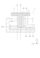
- FIG. 1 is a cross-sectional view of a sealing structure according to an embodiment of the present invention.
- 2 is a cross-sectional view of a first member and a second member in which a sealing structure according to an embodiment of the present invention is formed.
- FIG. 2 is a cross-sectional view of a sealing device provided in the sealing structure according to the embodiment of the present invention.
- 5 is a cross-sectional view showing a state in which an elastic body portion is deformed in a sealing device provided in a sealing structure according to an embodiment of the present invention.
- Fig. 1 is a cross-sectional view of a sealing structure 1 according to an embodiment of the present invention
- Fig. 2 is a cross-sectional view of a first member 2 and a second member 3 forming the sealing structure 1
- Fig. 3 is a cross-sectional view of a sealing device 4 provided in the sealing structure 1
- Fig. 4 is a cross-sectional view showing the state in which an elastic body portion 41 is deformed in the sealing device 4 provided in the sealing structure 1.
- the sealing device 4 provided in the sealing structure 1 according to the embodiment of the present invention seals between the first cylindrical portion 21 and the second cylindrical portion 31 inserted into the first cylindrical portion 21.
- the sealing device 4 has a cylindrical elastic portion 41 that is aligned with the first cylindrical portion 21 and the second cylindrical portion 31.
- the elastic portion 41 has at least two lip portions 413, 414 that extend circumferentially on an inner circumferential surface 412A that contacts the second cylindrical portion 31 and are arranged at a predetermined interval in the extension direction of the cylinder (Z direction).
- the first member 2 and the second member 3 are mounted on, for example, a vehicle and constitute a cooling device for cooling heat-generating parts such as an inverter. That is, the first member 2 and the second member 3 form fluid flow paths 2A, 3A through which coolant passes as a fluid.
- the second member 3 is provided inside the inverter and the first member 2 is provided outside the inverter, thereby forming a housing for the cooling device, but the present invention is not limited to such an arrangement.
- the first member 2 integrally has a first tubular portion 21 and a flow path forming portion 22.
- the first tubular portion 21 is formed in a cylindrical shape and is continuous with one end 221 of the flow path forming portion 22.
- the flow path forming portion 22 is formed in a cylindrical shape and extends perpendicular to the first tubular portion 21.
- a fluid flow path 2A through which cooling water can pass is formed inside the first tubular portion 21 and the flow path forming portion 22.
- the extension direction of the first cylindrical portion 21 (direction along the central axis) is referred to as the Z direction (vertical direction in FIG. 1)
- the extension direction of the flow path forming portion 22 is referred to as the X direction (horizontal direction in FIG. 1)
- the direction perpendicular to both the Z direction and the X direction is referred to as the Y direction (perpendicular to the paper surface in FIG. 1).
- the direction from the flow path forming portion 22 toward the opposite side is referred to as the upper side in the Z direction
- the opposite direction is referred to as the lower side in the Z direction (these upper and lower sides do not have to coincide with the upper and lower sides in the vertical direction).
- the direction toward the first cylindrical portion 21 is referred to as one side of the X direction (left side in FIG. 1)
- the opposite direction is referred to as the other side of the X direction (right side in FIG. 1).
- the second member 3 integrally has a second tubular portion 31 and a flow path forming portion 32.
- the second tubular portion 31 is formed in a cylindrical shape extending in the Z direction and is connected to the middle portion of the flow path forming portion 32.
- the flow path forming portion 32 is formed in a cylindrical shape and extends in the X direction perpendicular to the second tubular portion 31. That is, the second tubular portion 31 extends so as to branch off from the flow path forming portion 32, and a T-shaped connection portion is formed.
- a fluid flow path 3A through which cooling water can pass is formed inside the second tubular portion 31 and the flow path forming portion 32.
- the outer diameter of the second cylindrical portion 31 is smaller than the inner diameter of the first cylindrical portion 21, and the second cylindrical portion 31 is inserted into the first cylindrical portion 21.
- the central axis z2 of the second cylindrical portion 31 is located on the other side in the X direction with respect to the central axis z1 of the first cylindrical portion 21.
- the first cylindrical portion 21 and the second cylindrical portion 31 are eccentric. Note that, for convenience of explanation, such eccentricity is omitted in FIG. 1.
- the amount of eccentricity may be, for example, 2.5 mm TIR.
- the fluid flow path 2A of the first member 2 and the fluid flow path 3A of the second member 3 are connected.
- the first member 2 and the second member 3 are fixed so that they cannot move relative to each other (including linear movement and rotational movement).
- the sealing device 4 is a gasket formed into a cylindrical shape as a whole, and has an elastic body portion 41 and a reinforcing member 42.
- the sealing device 4 is disposed in the cylindrical gap 5 formed between the first cylindrical portion 21 and the second cylindrical portion 31, and serves to seal this gap 5.
- the elastic body constituting the elastic body portion 41 may be, for example, synthetic rubber such as nitrile rubber (NBR), hydrogenated nitrile rubber (H-NBR), acrylic rubber (ACM), or fluororubber (FKM).
- NBR nitrile rubber
- H-NBR hydrogenated nitrile rubber
- ACM acrylic rubber
- FKM fluororubber
- the elastic body portion 41 is formed cylindrically as a whole, and has an outer cylindrical portion 411 and an inner cylindrical portion 412.
- the outer cylindrical portion 411 is a fixed portion that is fixed to the inner circumferential surface 21A of the first cylindrical portion 21.
- the inner cylindrical portion 412 is continuous with the upper end of the outer cylindrical portion 411 in the Z direction, and extends downward so as to approach the center of the tube.
- the inner cylindrical portion 412 has two lip portions 413, 414 on the inner peripheral surface 412A.
- the inner peripheral surface 412A of the inner cylindrical portion 412 is also the inner peripheral surface of the entire elastic body portion 41.
- the lip portions 413, 414 are formed in an annular shape by extending along the circumferential direction with respect to the axis along the Z direction.
- the upper lip portion 413 has an apex portion 413A so as to be in linear contact with the outer peripheral surface 31A.
- the lower lip portion 414 has a contact surface portion 414A having a predetermined Z direction dimension so as to be in planar contact with the outer peripheral surface 31A.
- the apex portion 413A and the upper end portion 414B of the contact surface portion 414A are arranged with a gap in the Z direction that is equal to or larger than the size of the expected foreign object.
- the distance between the apex 413A and the upper end 414B is 1 mm or more, and if the length of the foreign object is 2 mm, it is preferable that the distance between the apex 413A and the upper end 414B is 2 mm or more.
- the reinforcing member 42 is integrally formed with a cylindrical tube portion 421 extending in the Z direction and an annular flange portion 422 along the XY plane, and is formed with an L-shaped cross section.
- the tube portion 421 is embedded in the outer tube portion 411 of the elastic body portion 41.
- the flange portion 422 is connected to the upper end of the tube portion 421 and extends toward the inner circumference, and is located at the connection portion between the outer tube portion 411 and the inner tube portion 412.
- the sealing device 4 described above When the sealing device 4 described above is disposed in the gap 5 between the eccentric first cylindrical portion 21 and the second cylindrical portion 31, the outer cylindrical portion 411 of the sealing device 4 is fixed to the inner circumferential surface 21A of the first cylindrical portion 21. At this time, the lip portions 413, 414 contact the outer circumferential surface 31A of the second cylindrical portion 31 over the entire circumference. Furthermore, due to the above-mentioned eccentricity, as shown in FIG. 4, the closer to the other side in the X direction where the first cylindrical portion 21 and the second cylindrical portion 31 are closely arranged, the more likely the elastic portion 41 of the sealing device 4 is to be compressed.
- the part of the inner cylindrical portion 412 is deformed so as to approach the outer cylindrical portion 411, and the part of the lip portions 413, 414, particularly the part on the other side in the X direction, is easily compressed.
- the lip portions 413 and 414 each have a contact area 6 and 7 that contacts the outer peripheral surface 31A, and in particular the contact area 6 expands from one side to the other side in the X direction.
- the lip portion 413 has a minimum contact width (Z-direction dimension) on one side in the X-direction, for example, 0.6 mm.
- the lip portion 414 has a minimum contact width (Z-direction dimension) on one side in the X-direction, for example, 1.6 mm.
- the lip portions 413 and 414 have a high contact pressure on the other side in the X direction, making it difficult for foreign matter to pass through.
- the contact pressure of the lip portions 413 and 414 on one side in the X direction is relatively small, a gap is easily formed between them because the amount of deformation of the lip portions 413 and 414 is small.
- the distance between the apex portion 413A and the upper end portion 414B before deformation is equal to or larger than the expected size of the foreign matter, and the amount of deformation on one side in the X direction is small, making it easy to maintain such a gap.
- the other of the two lip portions 413 and 414 maintains contact with the outer circumferential surface 31A over the entire circumference, making it easier to maintain sealing properties.
- the elastic body portion 41 of the sealing device 4 has two lip portions 413, 414 arranged at a predetermined distance in the Z direction, thereby ensuring sealing between the first member 2 and the second member 3, which are two members that are connected while being eccentric.
- the sealing device 4 has a reinforcing member 42, but depending on the material of the elastic body and the dimensions of each part, the reinforcing member may be omitted.
- the lip portion 413 has a lip shape that makes linear contact with the outer peripheral surface 31A
- the lip portion 414 has a lip shape that makes planar contact
- the contact manner of the lip portions is not particularly limited, and for example, both lip portions may make linear contact or both may make planar contact.
- the elastic body portion 41 has two lip portions 413, 414, but the elastic body portion may have three or more lip portions.
- the three or more lip portions may include two adjacent lip portions spaced apart by a predetermined distance (for example, 1.3 mm or more in the above embodiment).
- the present invention is not limited to the above-mentioned embodiments of the present invention, but includes all aspects included in the concept and scope of the claims of the present invention. Furthermore, each configuration may be appropriately and selectively combined to achieve at least some of the above-mentioned problems and effects.
- the shape, material, arrangement, size, etc. of each component in the above-mentioned embodiments may be appropriately changed depending on the specific usage mode of the present invention.
- 1...sealing structure 2...first member, 21...first cylindrical portion, 21A...inner circumferential surface, 22...flow path forming portion, 221...one end, 2A, 3A...fluid flow path, 3...second member, 31...second cylindrical portion, 31A...outer circumferential surface, 32...flow path forming portion, 4...sealing device, 41...elastic body portion, 411...outer cylindrical portion, 412...inner cylindrical portion, 413, 414...lip portion, 413A...apex portion, 414A...contact surface portion, 414B...upper end portion, 42...reinforcing member, 421...cylindrical portion, 422...flange portion, 5...gap, 6, 7...contact area
Landscapes
- Engineering & Computer Science (AREA)
- General Engineering & Computer Science (AREA)
- Mechanical Engineering (AREA)
- Gasket Seals (AREA)
Priority Applications (3)
| Application Number | Priority Date | Filing Date | Title |
|---|---|---|---|
| JP2024565808A JP7852842B2 (ja) | 2022-12-19 | 2023-12-08 | 密封装置 |
| EP23906782.0A EP4641051A1 (en) | 2022-12-19 | 2023-12-08 | Sealing device |
| CN202380087731.1A CN120390855A (zh) | 2022-12-19 | 2023-12-08 | 密封装置 |
Applications Claiming Priority (2)
| Application Number | Priority Date | Filing Date | Title |
|---|---|---|---|
| JP2022-201885 | 2022-12-19 | ||
| JP2022201885 | 2022-12-19 |
Publications (1)
| Publication Number | Publication Date |
|---|---|
| WO2024135416A1 true WO2024135416A1 (ja) | 2024-06-27 |
Family
ID=91588614
Family Applications (1)
| Application Number | Title | Priority Date | Filing Date |
|---|---|---|---|
| PCT/JP2023/044070 Ceased WO2024135416A1 (ja) | 2022-12-19 | 2023-12-08 | 密封装置 |
Country Status (4)
| Country | Link |
|---|---|
| EP (1) | EP4641051A1 (https=) |
| JP (1) | JP7852842B2 (https=) |
| CN (1) | CN120390855A (https=) |
| WO (1) | WO2024135416A1 (https=) |
Citations (5)
| Publication number | Priority date | Publication date | Assignee | Title |
|---|---|---|---|---|
| JPH03124087U (https=) * | 1990-03-30 | 1991-12-17 | ||
| JPH08121247A (ja) * | 1994-10-27 | 1996-05-14 | Tsuchiya Mfg Co Ltd | シリンダヘッドカバーにおける点火栓挿入部のシール装置 |
| EP1748232A1 (fr) * | 2005-07-29 | 2007-01-31 | Carl Freudenberg KG | Joint pour puits de bougie |
| JP2020041634A (ja) | 2018-09-12 | 2020-03-19 | 内山工業株式会社 | ガスケット |
| JP2020183811A (ja) * | 2019-05-02 | 2020-11-12 | プレス−シール コーポレーション | ポリマー管用管継手シール |
-
2023
- 2023-12-08 WO PCT/JP2023/044070 patent/WO2024135416A1/ja not_active Ceased
- 2023-12-08 EP EP23906782.0A patent/EP4641051A1/en active Pending
- 2023-12-08 JP JP2024565808A patent/JP7852842B2/ja active Active
- 2023-12-08 CN CN202380087731.1A patent/CN120390855A/zh active Pending
Patent Citations (5)
| Publication number | Priority date | Publication date | Assignee | Title |
|---|---|---|---|---|
| JPH03124087U (https=) * | 1990-03-30 | 1991-12-17 | ||
| JPH08121247A (ja) * | 1994-10-27 | 1996-05-14 | Tsuchiya Mfg Co Ltd | シリンダヘッドカバーにおける点火栓挿入部のシール装置 |
| EP1748232A1 (fr) * | 2005-07-29 | 2007-01-31 | Carl Freudenberg KG | Joint pour puits de bougie |
| JP2020041634A (ja) | 2018-09-12 | 2020-03-19 | 内山工業株式会社 | ガスケット |
| JP2020183811A (ja) * | 2019-05-02 | 2020-11-12 | プレス−シール コーポレーション | ポリマー管用管継手シール |
Non-Patent Citations (1)
| Title |
|---|
| See also references of EP4641051A1 |
Also Published As
| Publication number | Publication date |
|---|---|
| CN120390855A (zh) | 2025-07-29 |
| JP7852842B2 (ja) | 2026-04-28 |
| EP4641051A1 (en) | 2025-10-29 |
| JPWO2024135416A1 (https=) | 2024-06-27 |
Similar Documents
| Publication | Publication Date | Title |
|---|---|---|
| CN108603597B (zh) | 密封垫 | |
| WO2008013147A1 (en) | Mechanical seal device | |
| JP3022489B2 (ja) | 密封装置 | |
| CN109073090B (zh) | 机械密封件 | |
| CN103946545B (zh) | 用于压缩机的气缸的密封套、压缩机和冷却设备 | |
| KR102437869B1 (ko) | 시일 및 시일 기구 | |
| JP2023012342A (ja) | 密封装置 | |
| WO2024135416A1 (ja) | 密封装置 | |
| JPWO2006070568A1 (ja) | 密封装置 | |
| CN113874640B (zh) | 密封装置 | |
| JP7458278B2 (ja) | 密封装置 | |
| CN104033609A (zh) | 密封环 | |
| JP2025159732A (ja) | 密封構造 | |
| WO2019230238A1 (ja) | シールリング及び密封構造 | |
| JP2025538788A (ja) | プラグコネクタ | |
| WO2021070482A1 (ja) | 密封装置 | |
| JP7127552B2 (ja) | 弁装置 | |
| US20250243937A1 (en) | Sealing Device | |
| TWI909760B (zh) | 滾珠螺桿及滾珠螺桿用密封零件 | |
| CN113994127B (zh) | 密封装置 | |
| JP7691296B2 (ja) | 密封装置 | |
| TW202018222A (zh) | 旋轉接頭 | |
| JP2008121846A (ja) | バックアップリング | |
| RU2180063C1 (ru) | Уплотнительное устройство для защиты подшипников вращающегося вала | |
| JP7432236B2 (ja) | フランジ継手 |
Legal Events
| Date | Code | Title | Description |
|---|---|---|---|
| 121 | Ep: the epo has been informed by wipo that ep was designated in this application |
Ref document number: 23906782 Country of ref document: EP Kind code of ref document: A1 |
|
| WWE | Wipo information: entry into national phase |
Ref document number: 2024565808 Country of ref document: JP |
|
| WWE | Wipo information: entry into national phase |
Ref document number: 202380087731.1 Country of ref document: CN |
|
| WWE | Wipo information: entry into national phase |
Ref document number: 2023906782 Country of ref document: EP |
|
| NENP | Non-entry into the national phase |
Ref country code: DE |
|
| ENP | Entry into the national phase |
Ref document number: 2023906782 Country of ref document: EP Effective date: 20250721 |
|
| WWP | Wipo information: published in national office |
Ref document number: 202380087731.1 Country of ref document: CN |
|
| ENP | Entry into the national phase |
Ref document number: 2023906782 Country of ref document: EP Effective date: 20250721 |
|
| ENP | Entry into the national phase |
Ref document number: 2023906782 Country of ref document: EP Effective date: 20250721 |
|
| WWP | Wipo information: published in national office |
Ref document number: 2023906782 Country of ref document: EP |