WO2024135282A1 - 送風装置 - Google Patents
送風装置 Download PDFInfo
- Publication number
- WO2024135282A1 WO2024135282A1 PCT/JP2023/043006 JP2023043006W WO2024135282A1 WO 2024135282 A1 WO2024135282 A1 WO 2024135282A1 JP 2023043006 W JP2023043006 W JP 2023043006W WO 2024135282 A1 WO2024135282 A1 WO 2024135282A1
- Authority
- WO
- WIPO (PCT)
- Prior art keywords
- air
- blowing
- blow
- airflow
- nozzle
- Prior art date
- Legal status (The legal status is an assumption and is not a legal conclusion. Google has not performed a legal analysis and makes no representation as to the accuracy of the status listed.)
- Ceased
Links
Images





Classifications
-
- E—FIXED CONSTRUCTIONS
- E04—BUILDING
- E04H—BUILDINGS OR LIKE STRUCTURES FOR PARTICULAR PURPOSES; SWIMMING OR SPLASH BATHS OR POOLS; MASTS; FENCING; TENTS OR CANOPIES, IN GENERAL
- E04H1/00—Buildings or groups of buildings for dwelling or office purposes; General layout, e.g. modular co-ordination or staggered storeys
- E04H1/12—Small buildings or other erections for limited occupation, erected in the open air or arranged in buildings, e.g. kiosks, waiting shelters for bus stops or for filling stations, roofs for railway platforms, watchmen's huts or dressing cubicles
-
- F—MECHANICAL ENGINEERING; LIGHTING; HEATING; WEAPONS; BLASTING
- F04—POSITIVE - DISPLACEMENT MACHINES FOR LIQUIDS; PUMPS FOR LIQUIDS OR ELASTIC FLUIDS
- F04F—PUMPING OF FLUID BY DIRECT CONTACT OF ANOTHER FLUID OR BY USING INERTIA OF FLUID TO BE PUMPED; SIPHONS
- F04F5/00—Jet pumps, i.e. devices in which flow is induced by pressure drop caused by velocity of another fluid flow
- F04F5/14—Jet pumps, i.e. devices in which flow is induced by pressure drop caused by velocity of another fluid flow the inducing fluid being elastic fluid
- F04F5/16—Jet pumps, i.e. devices in which flow is induced by pressure drop caused by velocity of another fluid flow the inducing fluid being elastic fluid displacing elastic fluids
- F04F5/20—Jet pumps, i.e. devices in which flow is induced by pressure drop caused by velocity of another fluid flow the inducing fluid being elastic fluid displacing elastic fluids for evacuating
-
- F—MECHANICAL ENGINEERING; LIGHTING; HEATING; WEAPONS; BLASTING
- F04—POSITIVE - DISPLACEMENT MACHINES FOR LIQUIDS; PUMPS FOR LIQUIDS OR ELASTIC FLUIDS
- F04F—PUMPING OF FLUID BY DIRECT CONTACT OF ANOTHER FLUID OR BY USING INERTIA OF FLUID TO BE PUMPED; SIPHONS
- F04F5/00—Jet pumps, i.e. devices in which flow is induced by pressure drop caused by velocity of another fluid flow
- F04F5/44—Component parts, details, or accessories not provided for in, or of interest apart from, groups F04F5/02 - F04F5/42
- F04F5/48—Control
-
- F—MECHANICAL ENGINEERING; LIGHTING; HEATING; WEAPONS; BLASTING
- F24—HEATING; RANGES; VENTILATING
- F24F—AIR-CONDITIONING; AIR-HUMIDIFICATION; VENTILATION; USE OF AIR CURRENTS FOR SCREENING
- F24F13/00—Details common to, or for air-conditioning, air-humidification, ventilation or use of air currents for screening
- F24F13/02—Ducting arrangements
- F24F13/06—Outlets for directing or distributing air into rooms or spaces, e.g. ceiling air diffuser
-
- F—MECHANICAL ENGINEERING; LIGHTING; HEATING; WEAPONS; BLASTING
- F24—HEATING; RANGES; VENTILATING
- F24F—AIR-CONDITIONING; AIR-HUMIDIFICATION; VENTILATION; USE OF AIR CURRENTS FOR SCREENING
- F24F7/00—Ventilation
- F24F7/007—Ventilation with forced flow
-
- F—MECHANICAL ENGINEERING; LIGHTING; HEATING; WEAPONS; BLASTING
- F24—HEATING; RANGES; VENTILATING
- F24F—AIR-CONDITIONING; AIR-HUMIDIFICATION; VENTILATION; USE OF AIR CURRENTS FOR SCREENING
- F24F7/00—Ventilation
- F24F7/04—Ventilation with ducting systems, e.g. by double walls; with natural circulation
- F24F7/06—Ventilation with ducting systems, e.g. by double walls; with natural circulation with forced air circulation, e.g. by fan positioning of a ventilator in or against a conduit
-
- F—MECHANICAL ENGINEERING; LIGHTING; HEATING; WEAPONS; BLASTING
- F24—HEATING; RANGES; VENTILATING
- F24F—AIR-CONDITIONING; AIR-HUMIDIFICATION; VENTILATION; USE OF AIR CURRENTS FOR SCREENING
- F24F2110/00—Control inputs relating to air properties
- F24F2110/50—Air quality properties
- F24F2110/65—Concentration of specific substances or contaminants
- F24F2110/72—Carbon monoxide
Definitions
- This disclosure relates to a blower device that is installed in a living space and blows air from the ceiling side toward the floor side.
- a ventilation device that quickly ventilates small living spaces such as booths used by individuals by sucking in air from within the living space over a wide area and then discharging it (see, for example, Patent Document 1).
- This disclosure provides a technology for a blower in a living space that allows ventilation while maintaining comfort all year round.
- the air blower device is an air blower device that blows air from the ceiling side of a living space above a user's head in a living space having a seating portion on which a user can sit, and is equipped with four or more blowing nozzles that are arranged on the ceiling side of the living space and each have a slit-shaped blowing outlet that blows out air flowing from the ceiling side of the living space toward the floor side of the living space, an air intake port for supplying air from outside the living space into the living space, an exhaust port for discharging air from inside the living space to the outside, four or more blowers that suck in air supplied from the air intake port and blow the sucked air toward the four or more blowing nozzles, and a control unit that controls the operation of the four or more blowers.
- the four or more blowing nozzles are arranged side by side with gaps between them so that their respective blowing outlets are located on the same plane, forming an air blowing surface.
- the control unit identifies one or more of the four or more blowing nozzles that are located vertically above the user seated on the seat as a first blowing nozzle, and identifies one or more of the four or more blowing nozzles other than the first blowing nozzle as a second blowing nozzle, and controls the operation of the four or more blowers by switching between a first blowing mode in which air drawn in from the air intake is blown to the first blowing nozzle and the second blowing nozzle, and a second blowing mode in which air drawn in from the air intake is selectively blown to the second blowing nozzle without being blown to the first blowing nozzle.
- This disclosure provides a technology for a blower in a living space that allows ventilation while maintaining comfort all year round.
- FIG. 1 is a perspective view showing a booth in which a blower device according to a first embodiment of the present disclosure is installed.
- FIG. 2 is a side view showing the flow of the air current generated by the blower device.
- FIG. 3 is a partial cross-sectional view seen from the front, showing the flow of airflow generated by the blower in the first blowing mode.
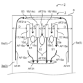
- FIG. 4 is a front view showing the flow of air currents generated by the blower in the first blowing mode with respect to a user seated in the center of the booth.
- FIG. 5 is a front view showing the flow of air currents generated by the blower in the second blowing mode with respect to a user seated in the center of the booth.
- FIG. 1 is a perspective view showing a booth in which a blower device according to a first embodiment of the present disclosure is installed.
- FIG. 2 is a side view showing the flow of the air current generated by the blower device.
- FIG. 3 is a partial cross-sectional view seen from the
- FIG. 6 is a front view showing the flow of air currents generated in the first blowing mode of the blower for a user seated at the end of the booth.
- FIG. 7 is a front view showing the flow of the airflow generated in the second blowing mode of the blower for a user seated at the end of the booth.
- FIG. 8 is a schematic functional block diagram of the blower.
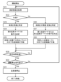
- FIG. 9 is a flowchart showing the control of the blower device.
- FIG. 10 is a schematic functional block diagram of a blower device according to a first modified example.
- FIG. 11 is a flowchart showing control in the blower device according to the first modified example.
- FIG. 12 is a flowchart showing control in the blower device according to the second modified example.
- the air blower device is an air blower device that blows air from the ceiling side of a living space above a user's head in a living space having a seating portion on which a user can sit, and is equipped with four or more blowing nozzles that are arranged on the ceiling side of the living space and each have a slit-shaped blowing outlet that blows out air flowing from the ceiling side of the living space toward the floor side of the living space, an air intake port for supplying air from outside the living space into the living space, an exhaust port for discharging air from inside the living space to the outside, four or more blowers that suck in air supplied from the air intake port and blow the sucked air toward the four or more blowing nozzles, and a control unit that controls the operation of the four or more blowers.
- the four or more blowing nozzles are arranged side by side with gaps between them so that their respective blowing outlets are located on the same plane, forming an air blowing surface.
- the control unit identifies one or more of the four or more blowing nozzles that are located vertically above the user seated on the seat as a first blowing nozzle, and identifies one or more of the four or more blowing nozzles other than the first blowing nozzle as a second blowing nozzle, and controls the operation of the four or more blowers by switching between a first blowing mode in which air drawn in from the air intake is blown to the first blowing nozzle and the second blowing nozzle, and a second blowing mode in which air drawn in from the air intake is selectively blown to the second blowing nozzle without being blown to the first blowing nozzle.
- the mode when ventilating the living space (air taken in from outside the living space is blown into the living space to replace the air within the living space), rather than blowing air randomly into the living space, in winter the mode can be switched to the second air blowing mode so that air is blown away from seated occupants. Meanwhile, in summer the mode can be switched to the first air blowing mode so that air is blown toward seated occupants.
- the air blower in the living space can ventilate while maintaining comfort all year round.
- control unit may control the operation of four or more blowers so that, in the first blowing mode, the volume of air blown out from the outlet of the first blowing nozzle is greater than the volume of air blown out from the outlet of the second blowing nozzle.
- the airflow formed by blowing out from the second blowing nozzle is attracted to the airflow formed by blowing out from the first blowing nozzle, so that the entire airflow combines to generate a highly straight-line airflow (surface airflow).
- a highly straight-line airflow can be blown towards the user. This allows the user to feel a stronger airflow, improving comfort.
- the air blowing device may further include a detection unit that detects the seating position of the user in the seating area, and the control unit may identify the first and second blowing nozzles based on the information on the seating position detected by the detection unit.
- blow nozzles identified as the first blow nozzle and the second blow nozzle depending on the user's seating position on the seating section.
- the blow nozzle vertically above the user can always be identified as the first blow nozzle.
- the control unit when the control unit receives a signal indicating that the current season is winter, the control unit may control the operation of the four or more blowers by switching to a third blowing mode in which air drawn in from the air intake port is blown toward two of the four or more blowing nozzles located at both ends, regardless of the user's seating position in the seating area.
- FIG. 1 is a perspective view showing a booth 2 in which a blower 1 according to a first embodiment of the present disclosure is installed. More specifically, FIG. 1(a) is an external perspective view showing the booth 2 in which the blower 1 is installed, and FIG. 1(b) is a see-through perspective view showing the booth 2 in which the blower 1 is installed.
- FIG. 2 is a side view showing the flow of airflow generated by the blower 1.
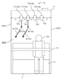
- FIG. 3 is a front view showing the flow of airflow generated in the first blowing mode of the blower 1. Note that in FIG. 2, the airflow is shown as blower nozzle 14, without distinguishing between blower nozzles 14a, 14b, 14c, and 14d.
- the booth 2 in which the blower 1 according to the first embodiment is installed is an equipment unit that has a relatively small space (living space 3a) in which at least one person can stay, and in which the air outlet of the blower 1 is located on the ceiling side.
- the booth 2 is a private room for one person equipped with a desk 12 and a seat 13 for remote work or study, and can also be called a private booth.
- the booth 2 is a rectangular parallelepiped housing, and has a floor board 4, multiple side panels 5, a top board 6, an inner panel 7, a door 11, an air intake vent 21, and an exhaust vent 22.
- the booth 2 also has a living space 3a and a hollow space 3b inside as the space 3 within the booth 2.
- the floorboard 4 is a rectangular board that is placed on the floor side of the booth 2.
- the multiple side panels 5 are made up of four rectangular plate members, side panel 5a, side panel 5b, side panel 5c, and side panel 5d, and stand vertically upward from the four outer peripheral edges of the floorboard 4.
- Side panel 5a is a side panel 5 on which a door 11 is provided. Side panel 5a connects one end side (door 11 side) of side panel 5c to one end side (door 11 side) of side panel 5d.
- Side panel 5b is a side panel 5 that is positioned opposite side panel 5a, and connects the other end of side panel 5c (opposite side from door 11) to the other end of side panel 5d (opposite side from door 11).
- Side panel 5c is a side panel 5 that has an air intake 21, and connects one end of side panel 5a (on the right side as you face the door 11) to one end of side panel 5b (on the right side as you face the door 11).
- Side panel 5d is a side panel 5 that is positioned opposite side panel 5c and has an exhaust port 22, and connects the other end of side panel 5a (left side when facing door 11) to the other end of side panel 5b (left side when facing door 11).
- the top board 6 is a rectangular plate that covers the opening formed by the four upright side panels 5.
- the top board 6 is provided above the floor board 4, and corresponds to the ceiling surface of the booth 2 when the floor board 4 is the floor surface of the booth 2.
- a space 3 is defined by a floor board 4, four side panels 5, and a top board 6.
- the space 3 is a small space having a floor area of, for example, about 2 m2.
- the inner panel 7 is a rectangular plate that divides the space 3 in the booth 2 into a living space 3a where the user stays and a hollow space 3b in which the main components of the air blower 1, which will be described later, are installed.
- the inner panel 7 is installed on the floor board 4 so as to be located on the side panel 5c side.
- the living space 3a is a space where a user of the booth 2 (e.g., a user 100, see FIG. 2) can enter, exit, and stay. More specifically, the living space 3a is a main space in the space 3 of the booth 2, and is composed of a floorboard 4, side panels 5 (side panels 5a, 5b, and 5d), a top board 6, an inner panel 7, and a door 11.
- the living space 3a has a floor area of, for example, about 1.5 m2 .
- a desk 12 and a seat 13 are arranged at predetermined positions, as shown in FIG. 1(b).
- the door 11 is a member that users use when entering and exiting the living space 3a.
- the door 11 is provided on the side panel 5a.
- the desk 12 is a member on which a user staying in the living space 3a can place a computer or documents and work.
- the desk 12 is provided so as to abut against the side panel 5d.
- the seating portion 13 is a member on which a user staying in the living space 3a sits.
- the seating portion 13 is positioned so as to abut against the inner panel 7.
- the hollow space 3b is connected to the living space 3a, and is a space in which the main components of the blower 1 are installed. More specifically, the hollow space 3b is composed of a floorboard 4, side panels 5 (side panels 5a, 5b, and 5c), a top board 6, and an inner panel 7.
- the hollow space 3b has a floor area of, for example, about 0.5 m2.
- a plurality of chambers 18, a plurality of ducts 19, and a plurality of blowers 20 are arranged at predetermined positions in the hollow space 3b as the main components of the blower 1.
- the air intake 21 is a rectangular opening for supplying air from the outside into the living space 3a, and is provided on the floorboard 4 side of the side panel 5c.
- the air intake 21 draws in air from outside the booth 2 when the blower 20, which will be described later, is operated. Note that although the air intake 21 has been described as being rectangular, it is not limited to this and may be a polygon other than a rectangle, a circle, or the like.
- the exhaust port 22 is a rectangular opening for discharging air from the living space 3a to the outside, and is provided on the floorboard 4 side of the side panel 5d.
- the exhaust port 22 discharges air from the living space 3a when the blower 20, which will be described later, is operated. Note that although the exhaust port 22 has been described as being rectangular, it is not limited to this and may be a polygon other than a rectangle, a circle, or the like.
- the booth 2 may be made portable by providing movable parts such as casters (not shown) on the underside of the floor board 4 of the booth 2.
- movable parts such as casters (not shown) on the underside of the floor board 4 of the booth 2.
- the air intake vent 21 and the exhaust vent 22 may be provided in the floor board 4.
- the blower 1 is a device that blows out air flowing from the top board 6 side to the floor board 4 side in the living space 3a of the booth 2, generating a downward air current within the living space 3a.
- the blower device 1 has a plurality of (four in this embodiment) blow nozzles 14 (blow nozzles 14a, 14b, 14c, 14d), a plurality of chambers 18 (chambers 18a, 18b, 18c, 18d), a plurality of ducts 19 (ducts 19a, 19b, 19c, 19d), and a plurality of blowers 20 (blowers 20a, 20b, 20c, 20d) each corresponding to the plurality of blow nozzles 14, an operation panel 40, and a control unit 50.
- the blow-out nozzle 14 is a type of rectangular parallelepiped ventilation pipe into which air transported by the blower 20 flows.
- the blow-out nozzle 14 has a blow-out outlet 15 on the underside of the blow-out nozzle 14.
- the multiple blow-out nozzles 14 are installed at predetermined positions on the top board 6 side of the living space 3a, and blow out the air flowing from the top board 6 side toward the floor board 4 side from the multiple blow-out outlets 15.
- the multiple blow-out nozzles 14 are positioned offset downward from the top board 6, as shown in FIG. 2.
- a predetermined space a space in which a negative pressure region S3 (see FIG. 3), described below, occurs
- S3 a negative pressure region
- the multiple blow-out nozzles 14 extend horizontally from a position above the inner panel 7 toward the side panel 5d. At this time, the multiple blow-out nozzles 14 are each connected in communication with the multiple chambers 18 on the inner panel 7 side, which is the starting point.
- above the inner panel 7 means a position higher than the head of a standing person, specifically a position at a height of about 200 cm or more above the floorboard 4 in the living space 3a.
- extending horizontally means that it is installed in a direction parallel to the floorboard 4, which forms the floor surface, and the top board 6, which forms the ceiling surface, in the living space 3a.
- each of the four blowing nozzles 14 (14a, 14b, 14c, 14d) is arranged in parallel from one end to the other end from the inner panel 7 toward the side panel 5d. At this time, the four blowing nozzles 14 are arranged side by side at equal intervals d from each other when viewed from the front, as shown in FIG. 3.
- the multiple blow-out nozzles 14 are all arranged in the living space 3a such that the distance D between the multiple blow-out nozzles 14a and the side panel 5a is greater than the distance d between blow-out nozzle 14a and blow-out nozzle 14b.
- the multiple blow-out nozzles 14 are also arranged such that the distance D between blow-out nozzle 14d and the side panel 5b is also greater than the distance d between blow-out nozzle 14d and blow-out nozzle 14c.
- the distance D is 390 mm and the distance d is 146 mm, but the values of the distances D and d are not limited to these.
- the multiple air outlets 15a-15d are slit-shaped openings formed on the undersides of the multiple air outlet nozzles 14a-14d, respectively. In other words, the multiple air outlets 15 are provided facing downward. The multiple air outlets 15 each blow out the air that has flowed into the multiple air outlet nozzles 14, and that flows from the top board 6 toward the floor board 4.
- the air outlet 15 is provided on the surface that faces the floorboard 4 among the surfaces that form the rectangular parallelepiped air outlet nozzle 14.
- the air outlet 15 is a rectangular opening, and is formed so that the long side is the direction in which the air outlet nozzle 14 stands upright from the inner panel 7, and the short side is parallel to the surface direction of the inner panel 7.
- One air outlet 15 is provided for each air outlet nozzle 14.
- the air outlets 15 belonging to each of the multiple air outlet nozzles 14 are arranged on the same horizontal plane.
- the air outlets 15 belonging to each of the multiple air outlet nozzles 14 are arranged at the same height from the floorboard 4.
- the four blowing nozzles 14a-14d are arranged so that the four blowing outlets 15a-15d are positioned on the same plane, and are arranged side by side with the above-mentioned distances d and D to form an air blowing surface. Then, when the blowing device 1 is operating to blow air, the four blowing nozzles 14 are distinguished into a first blowing nozzle 16 and a second blowing nozzle 17 and used for blowing air based on information input to the operation panel 40.
- the first blowing nozzle 16 is one or more of the four blowing nozzles 14 that are located vertically above the user 100.
- the first blowing nozzle 16 is identified from the seating position of the user 100 on the seating section 13, which is input via the operation panel 40.
- the second blow-out nozzle 17 is one or more of the four blow-out nozzles 14 other than the first blow-out nozzle 16.
- the second blow-out nozzle 17 can be said to be a blow-out nozzle 14 that is not positioned vertically above the user 100 among the four blow-out nozzles 14.
- the chamber 18 is a housing that connects the blow-out nozzle 14 and the duct 19.
- the chamber 18 controls the air flow (airflow direction) toward the blow-out nozzle 14.
- blow-out nozzle 14 is connected to the side of the chamber 18, and the duct 19 is connected to the bottom of the chamber 18.
- the chamber 18 controls the flow direction of the air flowing in from the duct 19 so that it is directed toward the blow-out nozzle 14.
- One chamber 18 is connected to one blow-out nozzle 14. In other words, four chambers 18 are arranged, the same number as the blow-out nozzles 14. The chambers 18 are arranged above the inner panel 7.
- the shape of the chambers 18 is not particularly limited, as long as it can connect the blow-out nozzles 14 and the duct 19 in communication.
- the duct 19 is an air duct for transporting air drawn into the blower 20 from the air intake 21 to the chamber 18.
- One end of the duct 19 is connected to the chamber 18, and the other end is connected to the blower 20.
- One duct 19 is arranged for one chamber 18. That is, in the example of FIG. 2, four ducts 19 are arranged as the multiple ducts 19.
- a known flexible duct can be used as the duct 19, for example.
- the blower 20 is a device that generates an airflow that flows from the air intake 21 through the duct 19 and the chamber 18 toward the outlet 15 of the blowing nozzle 14.
- a known turbo machine such as a centrifugal blower can be used.
- blower 20 is connected to one blowing nozzle 14. That is, the same number of blowers 20 are arranged as the blowing nozzles 14.
- the blowers 20 include blower 20a that blows air to blowing nozzle 14a, blower 20b that blows air to blowing nozzle 14b, blower 20c that blows air to blowing nozzle 14c, and blower 20d that blows air to blowing nozzle 14d, as shown in FIG. 1(b).
- the blower 20 generates an air flow from the air inlet 21 toward the blowing nozzle 14, and supplies the air sucked from the air inlet 21 to the blowing nozzle 14 via the duct 19 and the chamber 18.
- each of the multiple blowers 20 has a mechanism that can adjust the air volume (air supply volume). Details will be described later, but in this embodiment, in the first air blowing mode, the four blowers 20 are controlled so that the air volume of the blower 20 communicating with the first blowing nozzle 16 is greater than the air volume of the blower 20 communicating with the second blowing nozzle 17.
- the operation panel 40 is a controller that allows the user 100 of the booth 2 to select the air blowing mode (the first air blowing mode or the second air blowing mode described below) of the air blowing device 1.
- the operation panel 40 is, for example, a switch or a touch panel.
- the user 100 also uses the operation panel 40 to input and set the position where the user 100 will be seated on the seating section 13.
- the operation panel 40 is installed in the living space 3a of the booth 2, but may also be installed near the booth 2, such as on the outer wall of the booth 2.
- the operation panel 40 may also be a terminal that is operated from outside using a network.
- the control unit 50 is a control device that receives input signals from the operation panel 40 and sends instructions to blow air to the multiple fans 20.
- the control unit 50 may be configured as either hardware or software.
- the control unit 50 may have a computer (processor) and a storage unit (memory), and may be configured to realize the control described below by having the computer execute a program stored in the storage unit.
- the control unit 50 may be placed inside the seating area 13 as shown in FIG. 2, but the placement is not limited to this as long as it is not in a location that obstructs the movement of the user 100.
- the blower device 1 is configured as described above.
- the blower device 1 may also be provided with a filter for collecting dust and other particles contained in the air outside the booth 2 on each air passage through which the airflow blown out from the air inlet 21 toward the multiple air outlets 15 of the multiple air outlet nozzles 14 passes. This makes it possible to supply air containing less dust and other foreign matter to the living space 3a compared to air before it passed through the filter.
- the blower 20 is disposed downstream of the filter. This makes it possible to prevent foreign matter such as dust from accumulating on the blower 20. This makes it possible to reduce the possibility of a tracking phenomenon occurring in the blower 20 due to accumulated foreign matter such as dust and moisture.
- the blower 1 is a device that constantly ventilates the interior space of the living space 3a and prevents an increase in the carbon dioxide concentration within the living space 3a.
- the booth 2 is a small, enclosed space used by an individual. Therefore, unless the air in the booth 2 is intentionally replaced, the air in the living space 3a will stagnate. Therefore, when a user 100 stays in the living space 3a, the user's 100's own breathing will increase the carbon dioxide concentration in the living space 3a, causing it to exceed the standard value set out in the Building Sanitation Environment Management Standards, which could result in air pollution.
- the blower 1 blows air from the external space into the internal space of the living space 3a, replacing the air and preventing an increase in the carbon dioxide concentration in the living space 3a, allowing the user 100 to stay in comfort.
- the blower 1 operates the blower 20
- air is supplied from the external space of the living space 3a to the internal space of the living space 3a, and the air in the living space 3a is pushed out and exhausted, thereby ventilating the living space 3a.
- the carbon dioxide concentration in the living space 3a it is desirable for the carbon dioxide concentration in the living space 3a to be less than the standard value (for example, the carbon dioxide concentration in the living space 3a is less than 1000 ppm).
- the air blower 1 performs air blowing operation by switching between the first air blowing mode and the second air blowing mode via the control unit 50.
- the first blowing mode is a blowing operation mode in which the blower 20 blows air to the first blowing nozzle 16 and the second blowing nozzle 17.
- the first blowing mode is a mode in which air is blown using all four blowing nozzles 14, and can also be called a surface airflow mode.
- the four blowers 20 are controlled to perform blowing operation such that the amount of air blown from the first blowing nozzle 16 is greater than the amount of air blown from the second blowing nozzle 17, so that a highly linear airflow (surface airflow) is blown in the living space 3a.
- the second airflow mode is an airflow operation mode in which air is not blown to the first blowing nozzle 16, but is selectively blown to only the second blowing nozzle 17.
- the second airflow mode is a mode in which air is blown using some of the four blowing nozzles 14, and can also be called a partial airflow mode.
- the lower limit of the airflow volume blown by the blower 20 is set to an airflow volume that keeps the carbon dioxide concentration in the living space 3a below a reference value (e.g., a carbon dioxide concentration of 1000 ppm).
- the first and second airflow modes determine the flow and speed of the air that hits the user 100 in the living space 3a, assuming different seasonal use.
- the first airflow mode is intended for use mainly in the summer and intermediate periods (spring and autumn), while the second airflow mode is intended for use mainly in the winter.
- the flow of the air that hits the user 100 will be described later.
- the air blower 1 In the first air blowing mode, when the user 100 is in a sitting position to work on the seat 13, the air blower 1 operates to blow air so that the wind speed around the user 100 is equal to or higher than 0.4 m/s (e.g., 0.4 m/s to 0.7 m/s), which is the threshold for feeling airflow (the sensation of airflow flowing over the skin surface). Specifically, in the first air blowing mode, the air blower 1 is set so that the total airflow volume of the air blowers 20a, 20b, 20c, and 20d is equal to or higher than about 140 m3 /h.
- 0.4 m/s e.g., 0.4 m/s to 0.7 m/s
- the air blower 1 blows air so that the wind speed around the user 100 is less than 0.4 m/s (e.g., 0.2 m/s), which is the threshold for feeling airflow (the sensation of airflow flowing over the skin surface).
- the air blower 1 is set so that the total air volume of the air blown by the one or more blowing nozzles 14 specified as the second blowing nozzle 17 among the blowers 20a, 20b, 20c, and 20d is approximately 80 m3 /h or less.
- Figure 4 is a front view showing the airflow generated by the blower 1 in the first blowing mode for a user 100 seated in the center of the booth.
- air outside the booth 2 becomes airflow AF12 and is sucked in through the air intake 21.
- the air sucked in through the air intake 21 flows inside the duct 19 as airflow AF13 and is transported to the chamber 18.
- the air (airflow AF13) transported to chamber 18 is switched by chamber 18 from a vertically upward direction (from floor board 4 to top board 6) to a horizontal direction (from side panel 5c to side panel 5d).
- the air transported to chamber 18 is controlled as an air flow toward blow-out nozzle 14, and flows through the inside of blow-out nozzle 14 as airflow AF14.
- air (airflow AF14) that flows into the blow-out nozzle 14 is blown out as airflow AF15 from the blow-out port 15 downward, i.e., toward the floorboard 4.
- the air (airflow AF15) blown out from the air outlet 15 flows as airflow AF31 through the living space 3a toward the floorboard 4.
- the multiple blowers 20 transport air to the first blowing nozzle 16 and the second blowing nozzle 17.
- the blowing nozzles 14a to 14d the blowing nozzles 14b and 14c located above the user 100 constitute the first blowing nozzle, and the remaining blowing nozzles 14a and 14d constitute the second blowing nozzle 17.
- an airflow AF15b is generated from the outlet 15 of the first blowing nozzle 16, and an airflow AF15a is generated from the outlet 15 of the second blowing nozzle 17.
- the generated airflows AF15b and AF15a join together to form airflow AF31, which circulates through the living space 3a toward the floorboard 4.
- the amount of air blown out from the first blowing nozzle 16 is controlled to be greater than the amount of air blown out from the second blowing nozzle 17, so the airflow AF31 flowing toward the user 100 flows toward the floorboard 4 as a highly linear airflow (surface airflow).
- the highly linear airflow will be described later.
- part of the air (airflow AF31) that has reached the floorboard 4 is exhausted to the outside of the booth 2 from the exhaust port 22 as airflow AF31a.
- the other part of the air (airflow AF31) that has reached the floorboard 4 is reflected by the floorboard 4 to become airflow AF31b, and flows as airflow AF41, which is a return airflow that flows along the side panel 5 (side panel 5a and side panel 5b) toward the top board 6.
- Airflow AF31 a portion of the air (airflow AF31) that reaches the top surface of the desk 12 is also reflected by the top surface of the desk 12 to become airflow AF31c.
- Airflow AF31c flows as part of airflow AF41, which is an ascending airflow (hereinafter also referred to as a return airflow) that flows along the side panel 5 (side panel 5a and side panel 5b) toward the top board 6.
- the airflow AF31 circulates as a downward airflow in the central region of the living space 3a, while the airflow AF41 circulates as a return airflow in the end region of the living space 3a.
- a "return air passage” is formed in which the airflow AF41 circulates along the vicinity of the surface of the side panel 5 (side panel 5a and side panel 5b).
- the multiple fans 20 operate to transport air to the first blowing nozzle 16 and the second blowing nozzle 17. More specifically, when the operation of the blower device 1 is started, among the multiple fans 20a to 20d, the fans 20 (fan 20b and fan 20c) that blow air to the first blowing nozzle 16 (blowout nozzles 14b and 14c) are all controlled to operate at an air volume of 100 m 3 /h, and the fans 20 (fan 20a and fan 20d) that blow air to the second blowing nozzle 17 (blowout nozzles 14a and 14d) are all controlled to operate at an air volume of 50 m 3 /h.
- blowers 20a and 20d when blowers 20a and 20d are operated, air outside the booth 2 is sucked in through the air inlet 21, and airflow AF15a is blown out from outlet 15a of blow nozzle 14a and outlet 15d of blow nozzle 14d.
- airflow AF15b is blown out from outlet 15b of blow nozzle 14b and outlet 15c of blow nozzle 14c.
- the air volume of the two airflows AF15a is about 50 m3 /h corresponding to the air volume of the blower 20a and the blower 20d, respectively
- the air volume of the two airflows AF15b is about 100 m3 /h corresponding to the air volume of the blower 20b and the blower 20c, respectively.
- the total air volume of the airflow AF15 as a whole is about 300 m3 /h.
- a negative pressure region S1 is generated in the space between blow nozzle 14a and blow nozzle 14b
- a negative pressure region S2 is generated in the space between blow nozzle 14b and blow nozzle 14c
- a negative pressure region S1 is generated in the space between blow nozzle 14c and blow nozzle 14d.
- negative pressure also called negative pressure
- negative pressure area S1 and negative pressure area S2 are areas where the air pressure is lower than the surrounding air pressure.
- airflow AF21a Airflow AF21a
- airflow AF21b Airflow AF21a and airflow AF21b are also called induced airflows.
- the space between the multiple blowing nozzles 14 through which airflow AF21a or airflow AF21b flows is also called an induced air duct.
- the air in the space around the airflows AF21a and AF21b (the space near the inlet of the induction air duct) is drawn in by the airflows AF21a and AF21b, generating a negative pressure area S3 in the space between the multiple blow-out nozzles 14 and the top board 6.
- a return path is formed that serves as a path for introducing air that is induced into the induced air duct via the negative pressure area S3, and the air is then induced into the induced air duct.
- airflow AF41 is air flowing toward the space between the multiple blow-out nozzles 14 and the top board 6, but the direction of the airflow differs from that of airflow AF15a and airflow AF15b, and from that of airflow AF21a and airflow AF21b, and is an airflow (return airflow) flowing from the floor board 4 toward the top board 6.
- airflow AF41 disturbs the flow of airflow AF15a adjacent to airflow AF41, and can be a factor in preventing the straightness of the airflow.
- the air volume relationship between airflow AF15a and airflow AF15b is "airflow AF15b > airflow AF15a", so airflow AF15a is attracted to airflow AF15b adjacent to airflow AF15a.
- airflow AF15a is less susceptible to the influence of airflow AF41, so airflow AF31 can maintain a planar airflow that is a linear airflow in the blowing direction as a whole.
- the air blower 1 blows air from both the first blowing nozzle 16 and the second blowing nozzle 17, thereby forming a highly linear airflow (surface airflow) toward the user 100 within the living space 3a.
- Figure 5 is a front view showing the airflow generated in the second blowing mode of the blower 1 for a user 100 seated in the center of the booth.
- Figure 6 is a front view showing the airflow generated in the first blowing mode of the blower 1 for a user 100 seated at the end of the booth.
- Figure 7 is a front view showing the airflow generated in the second blowing mode of the blower 1 for a user 100 seated at the end of the booth.
- the two blowers 20 blowing air to the two first blowing nozzles 16 are both controlled to operate at an air volume of 100 m3 /h
- the two blowers 20 blowing air to the two second blowing nozzles 17 are both controlled to operate at an air volume of 50 m3 /h.
- each of the two blowers 20 that blow air to the two first blowing nozzles 16 is controlled to operate at an air volume of 100 m3 /h.
- the following description will be made assuming that the flow is the same as the main airflow described above, and will be omitted as appropriate.
- blower device 1 In the first blowing mode, the blower device 1 generates an airflow that travels straight toward the user 100.
- blowing nozzle 14b and blowing nozzle 14c located vertically above the user 100 are identified as the first blowing nozzle 16, and the other blowing nozzles 14, blowing nozzle 14a and blowing nozzle 14d, are identified as the second blowing nozzle 17.
- blowers 20b and 20c that blow air to the first blowing nozzle 16 are activated, air outside the booth 2 is sucked in through the air intake 21, and airflow AF15b is blown out from the blowing outlet 15b of the blowing nozzle 14b and the blowing outlet 15c of the blowing nozzle 14c.
- blowers 20a and 20d which blow air to second blowing nozzle 17, also operate, sucking air from outside booth 2 through air intake 21, and blowing airflow AF15a out from blowing outlet 15a of blowing nozzle 14a and blowing outlet 15d of blowing nozzle 14d.
- Part of the airflow AF15a is attracted to the airflow AF15b and merges with it, or forms a return current that flows from the floorboard 4 side to the topboard 6 side.
- the air blowing device 1 blows air through the first air outlet nozzle 16 and the second air outlet nozzle 17, thereby generating an airflow AF31 that flows toward the user 100.
- the amount of air blown to the first blowing nozzle 16 is greater than the amount of air blown to the second blowing nozzle 17, so that, as described above, the airflow AF15a is more strongly attracted to the airflow AF15b, resulting in an airflow with a high degree of straightness. In other words, in the first air blowing mode, the air blown to the user 100 goes straight, making the user 100 feel cool.
- blow-out nozzle 14b and blow-out nozzle 14c located vertically above user 100 are identified as first blow-out nozzle 16, and the other blow-out nozzles 14, blow-out nozzle 14a and blow-out nozzle 14d, are identified as second blow-out nozzle 17.
- blower 20 that blows air to the second blowing nozzle 17 is operated.
- the blower 20b and the blower 20c that blow air to the first blowing nozzle 16 are not operated, and the blower 20a and the blower 20d that blow air to the second blowing nozzle 17 are operated.
- blowers 20a and 20d start operating, air outside the booth 2 is sucked in through the air intake 21, and airflow AF15a is blown out from the outlet 15a of blow nozzle 14a and the outlet 15d of blow nozzle 14d.
- the airflow AF15a blown out from the second blowing nozzle 17 is an airflow that flows near the wall surface (side panels 5a, 5b), so the Coanda effect comes into play and the airflow is drawn to the side panel 5, becoming airflow AF15c.
- Airflow AF15c is an airflow that flows near the side panel 5 from the top board 6 side toward the floor board 4 side.
- Airflow AF15c passes through the interior space of living space 3a, gently avoiding the user 100, and reaches the floorboard 4 side. After descending within living space 3a along side panels 5a and 5b, airflow AF15c changes to an exhaust airflow (airflow AF31a, see Figure 2) or a return airflow (airflow AF41), as in the first airflow mode.
- the air blowing device 1 selectively blows air only through the second outlet nozzle 17, thereby forming an air flow that descends along the side panel 5 within the living space 3a.
- the air does not blow directly at the user 100, preventing the user 100 from feeling cold.
- blow-out nozzle 14a and blow-out nozzle 14b located vertically above user 100 are identified as first blow-out nozzle 16, and the other blow-out nozzles 14, blow-out nozzle 14c and blow-out nozzle 14d, are identified as second blow-out nozzle 17.
- blowers 20a and 20b that blow air to the first blowing nozzle 16 are activated, air outside the booth 2 is sucked in through the air intake 21, and airflow AF15b is blown out from the blowing outlet 15a of the blowing nozzle 14a and the blowing outlet 15b of the blowing nozzle 14b.
- blowers 20c and 20d which blow air to second blowing nozzle 17, also operate, sucking air from outside booth 2 through air inlet 21, and blowing airflow AF15a out from blowing outlet 15c of blowing nozzle 14c and blowing outlet 15d of blowing nozzle 14d.
- the air in the space around the airflows AF15a and AF15b is drawn toward the airflows AF15a and AF15b, and the air in the entire living space 3a, centered around the user 100, descends from the top board 6 side toward the floor board 4 side.
- Part of the airflow AF15a is attracted to the airflow AF15b and merges with it, or forms a return current that flows from the floorboard 4 side to the topboard 6 side.
- the air blowing device 1 can generate an airflow that flows toward the user 100 by blowing air through the first air blowing nozzle 16 and the second air blowing nozzle 17, even if the user 100 is sitting at the end of the booth.
- the airflow AF15a is attracted to the airflow AF15b, resulting in a highly linear airflow.
- the air blown to the user 100 moves in a straight line, making the user 100 feel cool.
- blow-out nozzle 14a and blow-out nozzle 14b located vertically above user 100 are identified as first blow-out nozzle 16, and the other blow-out nozzles 14, blow-out nozzle 14c and blow-out nozzle 14d, are identified as second blow-out nozzle 17.
- blower 20 that blows air to the second blowing nozzle 17 is operated.
- the blower 20a and the blower 20b that blow air to the first blowing nozzle 16 are not operated, and the blower 20c and the blower 20d that blow air to the second blowing nozzle 17 are operated.
- blowers 20c and 20d start operating, air outside booth 2 is sucked in through air intake 21, and airflow AF15a is blown out from outlet 15c of blow nozzle 14c and outlet 15d of blow nozzle 14d.
- Airflow AF15a blown out from the air outlet 15d is an airflow that flows near the wall surface (side panel 5b), so the Coanda effect works and the airflow is drawn to the side panel 5, becoming airflow AF15c overall.
- Airflow AF15c is an airflow that flows near the side panel 5b from the top board 6 side toward the floor board 4 side.
- the airflow AF15a blown out from the air outlet 15c is attracted to the airflow AF15a blown out from the air outlet 15d and merges with the airflow AF15c.
- the airflow AF15c thus generated passes through the internal space of the living space 3a, gently avoiding the user 100, and reaches the floorboard 4 side. After descending within the living space 3a along the side panel 5b, the airflow AF15c changes to an exhaust airflow (airflow AF31a) or a return airflow (airflow AF41), as in the first airflow mode.
- the air blowing device 1 selectively blows air only through the second outlet nozzle 17, thereby forming an air flow that descends along the side panel 5b within the living space 3a.
- the air does not blow directly on the user 100, preventing the user from feeling cold.
- FIG. 8 is a schematic block diagram showing the configuration of the control unit 50.
- the control unit 50 of the blower device 1 includes an input unit 51, a memory unit 52, a timer unit 53, a processing unit 54, and an output unit 55.
- the control unit 50 controls the multiple blowers 20a to 20d based on input information from the operation panel 40.
- the input unit 51 accepts information input from the operation panel 40 (seating position information of the user 100 and airflow mode information) and outputs it to the processing unit 54.
- the seating position information is information about the position of the user 100 seated on the seating section 13
- the airflow mode information is information about the first airflow mode or the second airflow mode selected by the user 100.
- the memory unit 52 stores information on the air volume of the blower 20 corresponding to the first blowing nozzle 16 and information on the air volume of the blower 20 corresponding to the second blowing nozzle 17.
- the memory unit 52 also stores information inputted through the operation panel 40.
- the memory unit 52 outputs the various stored information to the processing unit 54 in response to a request from the processing unit 54.
- the timing unit 53 measures the time from when the blower device 1 starts blowing air, and outputs the operating time to the processing unit 54.
- the processing unit 54 receives information from the input unit 51, various information from the memory unit 52 (such as information about the air volume of the blower), and time information from the timing unit 53. Based on the received information, the processing unit 54 determines the blowing operation of the multiple blowers 20 (blower 20a, blower 20b, blower 20c, blower 20d). The processing unit 54 outputs information (control information) related to the determined blowing operation to the output unit 55.
- the output unit 55 outputs the control information received from the processing unit 54 to the blower 20.
- each of the multiple blowers 20 performs a blowing operation at an air volume based on the control information in response to the control information output from the output unit 55.
- control unit 50 causes the multiple blowers 20 in the blower device 1 to perform blowing operations.
- FIG. 9 is a flowchart showing the control of the blower 1.
- the control unit 50 acquires the seating position information of the user 100 and the blowing mode information selected by the user 100 as input information from the operation panel 40 (S01).
- the control unit 50 identifies the first blowing nozzle 16 of the four blowing nozzles 14 that is located vertically above the user 100 based on the acquired seating position information of the user 100 (center of the booth or end of the booth) (S02). Note that in step S02, the second blowing nozzle 17, which is the blowing nozzle 14 other than the first blowing nozzle 16, is also identified among the four blowing nozzles 14.
- the seating position information identified in step S02 is information that identifies whether the user is seated in the center of the booth or at the edge of the booth, but is also information that can identify whether the user 100 is seated biased toward the side panel 5a or side panel 5b of the seating section 13 at the edge of the booth.
- the control unit 50 appropriately selects the first blowing nozzle 16 and the second blowing nozzle 17 depending on the seating position of the user 100.
- control unit 50 determines whether the airflow mode selected by the user 100 is the first airflow mode based on the acquired airflow mode information (S03).
- step S03 determines whether the first airflow mode is selected (Yes in S03). If the result of the determination in step S03 is that the first airflow mode is selected (Yes in S03), the process proceeds to step S04a. On the other hand, if the result of the determination is that the first airflow mode is not selected, i.e., that the second airflow mode is selected (No in S03), the process proceeds to step S04b.
- control unit 50 causes the blower 20 to blow air to the first blowing nozzle 16 and the blower 20 to blow air to the second blowing nozzle 17 to perform blowing operations (S05a).
- step S04b the control unit 50 does not cause the blower 20 to blow air to the first blowing nozzle 16, but causes only the blower 20 to blow air to the second blowing nozzle 17 to perform the blowing operation (S05b).
- step S05a or step S05b the control unit 50 determines whether the time measured from the start time of the blowing operation by the blower 20 has elapsed a predetermined time (S06).
- the predetermined time is set to, for example, one minute.
- step S06 If the result of the determination in step S06 is that the predetermined time has not elapsed (No in S06), the control unit 50 continues the blowing operation of the blower 20 (return to S06).
- step S07 If the result of the determination is that the predetermined time has elapsed (Yes in S06), the process proceeds to step S07.
- step S07 it is determined whether or not a signal to stop operation of the blower device 1 has been input. If a signal to stop operation of the blower device 1 has not been input (No in S07), the control unit 50 returns to step S03 and continues to execute the operation of the blower device 1. At this time, the measured time is reset.
- step S06 determines whether the predetermined time has elapsed (Yes in S06) and an operation stop signal has been input (Yes in S07).
- the process proceeds to step S08, and the blower device 1 stops the blower 20 and enters an operation end state or standby state. Note that the blower device 1 can also stop the blower operation immediately when it receives an operation stop signal without waiting for the predetermined time to elapse.
- the blower device 1 in this embodiment can control the blowing operation of the blower 20 in accordance with the seating position of the user 100, and can switch between the first and second blowing modes.
- the blower device 1 according to the first embodiment provides the following advantages.
- the blower 1 is installed in a booth 2 having an occupant space 3a formed by a floorboard 4, a plurality of side panels 5, and a top board 6, an air inlet 21 for supplying air to the occupant space 3a, an exhaust port 22 for discharging air from the occupant space 3a, and a seating area 13 on which a user 100 can sit.
- the blower 1 is installed in the occupant space 3a on the top board 6 side of the occupant space 3a, above the head of a user 100 sitting on the seating area 13, and is offset from the top board 6.
- the blower 1 includes four blowing nozzles 14, each having a slit-shaped outlet for blowing air flowing from the top board 6 side toward the floorboard 4 side, four blowers 20 for blowing air sucked in from the air inlet 21 to each of the four blowing nozzles 14, and a control unit 50 for controlling the operation of the four blowers 20.
- the four blowing nozzles 14 are arranged side by side with a gap between them so that the respective blowing ports 15 are located on the same plane.
- the control unit 50 identifies, among the four blowing nozzles 14, the blowing nozzle 14 located vertically above the user 100 seated on the seating unit 13 as the first blowing nozzle 16, and identifies the blowing nozzles 14 other than the first blowing nozzle 16 as the second blowing nozzle 17.
- the control unit 50 controls the four blowers 20 by switching between a first blowing mode in which air sucked from the air supply port 21 is blown to the first blowing nozzle 16 and the second blowing nozzle 17, and a second blowing mode in which air sucked from the air supply port 21 is selectively blown to the second blowing nozzle 17 without blowing to the first blowing nozzle 16.
- the mode when ventilating the living space 3a (air taken in from outside the living space 3a is blown into the living space 3a to replace the air in the living space 3a), rather than blowing air randomly into the living space 3a, in winter the mode can be switched to the second air blowing mode so that air is blown away from seated users 100. On the other hand, in summer the mode can be switched to the first air blowing mode so that air is blown toward seated users 100.
- the air blower 1 in the living space 3a can ventilate while maintaining comfort all year round.
- control unit 50 controls the four blowers 20 in the first blowing mode so that the volume of air blown out from the outlet 15 of the first blowing nozzle 16 is greater than the volume of air blown out from the outlet 15 of the second blowing nozzle 17.
- the airflow formed by blowing out from the second blowing nozzle 17 is attracted to the airflow formed by blowing out from the first blowing nozzle 16, and the entire airflows combine to generate a highly straight-line airflow (surface airflow).
- a highly straight-line airflow can be blown towards the user 100. This allows the user 100 to feel the airflow more strongly, improving comfort.
- blower device 1a in the first modified example will be described with reference to Figures 10 and 11.
- FIG. 10 is a schematic functional block diagram of the blower device 1a according to the first modified example.
- FIG. 11 is a flowchart showing the control in the blower device 1a according to the first modified example.
- the blower device 1a according to the first modified example differs from the blower device 1 according to the first embodiment in that it is provided with a detection unit 30 for identifying the seating position of the user 100 in the seating section 13.
- the control unit 50a identifies the first blowing nozzle 16 and the second blowing nozzle 17 based on the seating position information of the user 100 detected by the detection unit 30.
- the air blower 1a in the first modified example further includes a detection unit 30.
- the detection unit 30 is a sensor for detecting the position where the user 100 sits on the seating section 13.
- the detection unit 30 is, for example, a pressure sensor, and is arranged near the seating surface of the seating section 13.
- the detection unit 30 is not limited to this form as long as it can detect the position of the user 100 on the seating section 13, and may be, for example, a device such as a thermal camera that can be arranged in the living space 3a and that can identify the seating position of the user 100 from temperature information, etc.
- the detection unit 30 By providing the detection unit 30, not only can it be detected whether the user 100 is seated at the center of the booth or at the edge of the booth, but it can also detect any position on the seating area 13 where the user 100 is seated. By accurately detecting the position where the user 100 is seated, the control unit 50a can appropriately select the first blowing nozzle 16 and the second blowing nozzle 17, and perform appropriate air supply control for the user 100.
- the control unit 50a of the blower device 1a according to the first modified example includes an input unit 51, a storage unit 52, a timer unit 53, a processing unit 54, and an output unit 55.
- the control unit 50a controls the multiple blowers 20a to 20d based on detection information from the detection unit 30 and input information from the operation panel 40.
- the input unit 51 accepts information detected by the detection unit 30 (seating position information of the user 100) and information inputted through the operation panel 40 (airflow mode information), and outputs it to the processing unit 54.
- the seating position information is information relating to the position of the user 100 seated on the seating section 13
- the airflow mode information is information relating to the first airflow mode or the second airflow mode selected by the user 100.
- the memory unit 52 stores information on the air volume of the blower 20 corresponding to the first blowing nozzle 16 and information on the air volume of the blower 20 corresponding to the second blowing nozzle 17.
- the memory unit 52 also stores information input from the operation panel 40.
- the memory unit 52 outputs the various stored information to the processing unit 54 in response to a request from the processing unit 54.
- the timing unit 53 measures the time from when the blower device 1 starts blowing air, and outputs the operating time to the processing unit 54.
- the processing unit 54 receives information from the input unit 51, various information from the memory unit 52 (such as information about the air volume of the blower), and time information from the timing unit 53. Based on the received information, the processing unit 54 determines the blowing operation of the multiple blowers 20 (blower 20a, blower 20b, blower 20c, blower 20d). The processing unit 54 outputs information (control information) related to the determined blowing operation to the output unit 55.
- the output unit 55 outputs the control information received from the processing unit 54 to the multiple fans 20.
- each of the multiple blowers 20 performs a blowing operation at an air volume based on the control information in response to the control information output from the output unit 55.
- control unit 50a causes the multiple blowers 20 in the blower device 1a to perform blowing operations.
- the control unit 50a acquires the seating position information of the user 100 as input information from the detection unit 30 (S11).
- the control unit 50a identifies the first blowing nozzle 16 of the four blowing nozzles 14 that is located vertically above the user 100 based on the acquired seating position information of the user 100 (center of the booth or end of the booth) (S12). Note that in step S12, the second blowing nozzle 17, which is the blowing nozzle 14 other than the first blowing nozzle 16, is also identified among the four blowing nozzles 14.
- control unit 50a acquires the airflow mode information selected by the user 100 as input information from the operation panel 40 (S13).
- control unit 50a operates the blower 20 corresponding to the blowing mode selected by the user 100 based on the acquired blowing mode information (S14). Specifically, the control unit 50a executes steps S03 to S05a or S05b that are performed by the control unit 50 in the first embodiment (see FIG. 9).
- control unit 50a determines whether the time measured from the start time of the blowing operation by the blower 20 in step S14 has elapsed a predetermined time (S15).
- the predetermined time is set to, for example, one minute.
- step S15 If the result of the determination in step S15 is that the predetermined time has not elapsed (No in S15), the control unit 50a continues the blowing operation of the blower 20 (return to S15).
- step S16 if the result of the determination is that the predetermined time has elapsed (Yes in S15), the process proceeds to step S16.
- step S16 it is determined whether or not a signal to stop operation of the blower device 1a has been input. If a signal to stop operation of the blower device 1a has not been input (No in S16), the control unit 50a returns to step S11 and continues to operate the blower device 1a. At this time, the measured time is reset.
- step S15 if the result of the determination in step S15 is that the predetermined time has elapsed (Yes in S15) and an operation stop signal has been input (Yes in S16), the process proceeds to step S17, and the blower device 1a stops the blower 20 and enters an operation end state or standby state.
- the blower device 1a can also immediately stop blowing operation if it receives an operation stop signal without waiting for the predetermined time to elapse.
- the air blowing device 1a in the first modified example can control the air blowing operation of the multiple air blowers 20 in response to the seating position of the user 100 detected by the detection unit 30, and can switch between the first air blowing mode and the second air blowing mode.
- the air blowing device 1a further includes a detection unit 30 that detects the seating position of the user 100 in the seating section 13.
- the control unit 50a then identifies the first blowing nozzle 16 and the second blowing nozzle 17 based on the information on the seating position detected by the detection unit 30.
- the blowing device 1a can be controlled so that the blowing nozzle 14 vertically above the user 100 is always the first blowing nozzle 16, regardless of the seating position of the user 100. Therefore, regardless of the seating position of the user 100, an airflow that directly hits the user 100 can be formed in the summer, and an airflow that does not directly hit the user 100 can be formed in the winter. As a result, regardless of where the user 100 sits in the seating section 13, ventilation can be performed while allowing the user 100 to spend time comfortably in the living space 3a.
- FIG. 12 is a flowchart showing the control performed by the blower device 1b according to the second modified example.
- the blower device 1b according to the second modified example differs from the blower device 1 according to the first embodiment in that it has a third blowing mode in which, when the control unit 50b receives a signal indicating that the current season is winter, air is selectively blown from two of the four blowing nozzles 14 located at both ends, regardless of the seating position of the user 100 in the seating section 13.
- a third blowing mode in which, when the control unit 50b receives a signal indicating that the current season is winter, air is selectively blown from two of the four blowing nozzles 14 located at both ends, regardless of the seating position of the user 100 in the seating section 13.
- the control unit 50b (similar in configuration to the control unit 50 in FIG. 8) of the blower device 1b in the second modified example performs blowing operation by switching between the first blowing mode, the second blowing mode, and the third blowing mode.
- the first and second air blowing modes are the same as those described in the first embodiment above. That is, in the first air blowing mode, the blower 20 blows air to the first blowing nozzle 16 and the second blowing nozzle 17, and in the second air blowing mode, the blower 20 selectively blows air only to the second blowing nozzle 17.
- the control unit 50b receives a signal indicating that the current season is winter, air is selectively blown from the two airflow nozzles 14 (airflow nozzle 14a and airflow nozzle 14d) located at both ends of the four airflow nozzles 14, regardless of the user's 100 seated position in the seating section 13.
- the third airflow mode also uses the two end blowing nozzles 14 out of the four blowing nozzles 14 to blow air, and can also be considered a partial airflow mode. Note that since there are four blowing nozzles 14 in the third airflow mode, the airflow state is essentially the same as the second airflow mode performed by the blower device 1 when the user 100 is seated in the center of the booth 2.
- the control unit 50b in the blower device 1b according to the second modified example determines the current season (e.g., summer, mid-season (spring, autumn), or winter), and if it determines that the season is winter, performs blowing operation in the third blowing mode.
- the current season e.g., summer, mid-season (spring, autumn), or winter
- the air blower device 1b determines that the season is winter, it executes a third air blowing mode in which air is blown only through the two air blowing nozzles 14 located at both ends of the four air blowing nozzles 14 arranged in the living space 3a.
- control unit 50b controls the blowers 20a and 20d to perform blowing operation so that air is blown out from the blowing nozzles 14a and 14d located at both ends.
- the airflow is sucked in through the air intake port 21 and directed toward the two airflow nozzles 14 located at both ends of the four airflow nozzles 14, regardless of the seating position of the user 100.
- the season determination by the control unit 50b may be performed by any method that can determine the season, and a detection means may be used in combination.
- a temperature sensor (not shown) that can detect the air temperature may be provided in a location where the temperature of the intake air in the booth 2 can be determined (such as the air intake port 21 or in the living space 3a), and the season may be determined from the temperature inside the booth 2, or a temperature sensor may be provided on a wall outside the booth 2, and the season may be determined from the air temperature in the space in which the booth 2 is installed.
- the processing unit 54 of the control unit 50b may also refer to the calendar information stored in the memory unit 52 based on the set date information and determine the season based on the date information.
- the PMV Predicted Mean Vote
- the operation mode of the air conditioner may be acquired to determine the season.
- blowing operation control of blower 20 performed in blower device 1b according to the second modification will be described with reference to Fig. 12.
- the blowing operation control has been described with reference to the control block diagrams for control unit 50 of the first embodiment and control unit 50a of the first modification, but in the second modification, the control block of control unit 50b is common to control units 50 and 50a, and therefore description thereof will be omitted.
- control unit 50b determines whether the season is winter or not (S22).
- step S22 If the result of the determination in step S22 is that the season is winter (Yes in S22), the control unit 50b identifies the season as winter (S23) and determines to operate the blower 20 in the third blowing mode (S24).
- control unit 50b activates the two blowers 20a, 20d that blow air to the two air blowing nozzles 14a, 14d located at both ends of the four air blowing nozzles 14 (S25).
- step S22 if the result of the judgment in step S22 is that the season is not winter (No in S22), that is, if the season is identified as mid-season or summer (S26), the control unit 50b refers to the input information from the operation panel 40 and decides whether to operate in the first airflow mode or the second airflow mode (S27).
- control unit 50b executes steps S01 to S04a or S04b that are performed by the control unit 50 in the first embodiment (see FIG. 9).
- the control unit 50b executes the blowing operation of the blower 20 according to the determined blowing mode (S28). Specifically, it executes step S05a or step S05b that is executed by the control unit 50 in the first embodiment (see FIG. 9).
- control unit 50b determines whether the time measured from the start time of the blowing operation by the blower 20 in step S25 or step S28 has elapsed a predetermined time (S29).
- the predetermined time is set to, for example, one minute.
- step S29 If the result of the determination in step S29 is that the predetermined time has not elapsed (No in S29), the control unit 50b continues the blowing operation of the blower 20 (return to S29).
- step S29 If the control unit 50b determines in step S29 that the predetermined time has elapsed (Yes in S29), the control unit 50b proceeds to step S30.
- step S30 it is determined whether or not a signal to stop operation of the blower device 1b has been input. If a signal to stop operation of the blower device 1b has not been input (No in S30), the process returns to step S21, and operation of the blower device 1b continues. At this time, the measured time is reset.
- step S29 if the result of the determination in step S29 is that the predetermined time has elapsed (Yes in S29) and an operation stop signal has been input (Yes in S30), the process proceeds to step S31, where the blower device 1b stops the blower 20 and goes into an operation end state or standby state.
- the blower device 1b can also stop the blowing operation immediately if it receives an operation stop signal without waiting for the predetermined time to elapse.
- the blower device 1b in the second modified example can acquire seasonal information, determine the season, control the blowing operation of the blower 20 in accordance with the result of the seasonal determination, and perform switching between the first blowing mode, the second blowing mode, and the third blowing mode.
- the control unit 50b controls the multiple blowers 20 to switch to a third blowing mode in which air drawn in from the air intake 21 is blown toward the two blowing nozzles 14 (blowout nozzle 14a and blowout nozzle 14d) located at both ends of the four blowing nozzles 14, regardless of the user's 100 seated position in the seating area 13.
- the blower device 1 is described using four blowing nozzles 14, but this is not limited to this. Five or more blowing nozzles may also be used.
- the living space 3a is a small space where an individual can stay, but this is not limited to this.
- the living space 3a is not limited to a private booth, but may be a conference room where multiple people can stay.
- the booth 2 has been described as being a box-shaped space, but it may be a semi-private space with no ceiling when the top board 6 is removed. Also, it may be a semi-private space with no door for entering or exiting and where people can freely enter or exit from the front or side of the booth 2 by removing the door 11 and the side panel 5a, 5b, or 5d.
- the desk 12 When the wall in front of the user 100 (side panel 5d) is removed, the desk 12 only needs to be placed in a place where it can be used by sitting on the seat 13, and it may be transformed into a shape supported by a side wall or a form that can be installed independently within the living space 3a (such as a portable table).
- the air blower according to the present disclosure is capable of blowing air while maintaining comfort when ventilating a room by switching the blowing nozzle used to blow air, and is therefore useful as an air blower to be installed in small rooms where individuals can stay.
Landscapes
- Engineering & Computer Science (AREA)
- Mechanical Engineering (AREA)
- General Engineering & Computer Science (AREA)
- Chemical & Material Sciences (AREA)
- Combustion & Propulsion (AREA)
- Architecture (AREA)
- Physics & Mathematics (AREA)
- Fluid Mechanics (AREA)
- Civil Engineering (AREA)
- Structural Engineering (AREA)
- Air Conditioning Control Device (AREA)
Priority Applications (1)
| Application Number | Priority Date | Filing Date | Title |
|---|---|---|---|
| JP2024565728A JPWO2024135282A1 (https=) | 2022-12-23 | 2023-11-30 |
Applications Claiming Priority (2)
| Application Number | Priority Date | Filing Date | Title |
|---|---|---|---|
| JP2022-207301 | 2022-12-23 | ||
| JP2022207301 | 2022-12-23 |
Publications (1)
| Publication Number | Publication Date |
|---|---|
| WO2024135282A1 true WO2024135282A1 (ja) | 2024-06-27 |
Family
ID=91588262
Family Applications (1)
| Application Number | Title | Priority Date | Filing Date |
|---|---|---|---|
| PCT/JP2023/043006 Ceased WO2024135282A1 (ja) | 2022-12-23 | 2023-11-30 | 送風装置 |
Country Status (2)
| Country | Link |
|---|---|
| JP (1) | JPWO2024135282A1 (https=) |
| WO (1) | WO2024135282A1 (https=) |
Citations (12)
| Publication number | Priority date | Publication date | Assignee | Title |
|---|---|---|---|---|
| JP2015224819A (ja) * | 2014-05-28 | 2015-12-14 | ダイダン株式会社 | コンタミネーション防止可能な安全キャビネット |
| JP2017160787A (ja) * | 2016-03-07 | 2017-09-14 | パナソニックIpマネジメント株式会社 | 送風装置 |
| JP2019060295A (ja) * | 2017-09-27 | 2019-04-18 | パナソニックIpマネジメント株式会社 | 送風装置 |
| JP2019148172A (ja) * | 2018-02-26 | 2019-09-05 | パナソニックIpマネジメント株式会社 | 送風装置 |
| WO2022004351A1 (ja) * | 2020-07-01 | 2022-01-06 | 未来を拓く合同会社 | エアカーテン装置及び殺菌送風装置 |
| WO2022000965A1 (zh) * | 2020-07-03 | 2022-01-06 | 湖南大学 | 一种有限空间空气稳定性的热舒适通风与污染物控制方法 |
| JP2022027488A (ja) * | 2020-07-31 | 2022-02-10 | パナソニックIpマネジメント株式会社 | 送風装置 |
| WO2022102529A1 (ja) * | 2020-11-12 | 2022-05-19 | シャープ株式会社 | 送風システム |
| JP2022148619A (ja) * | 2021-03-24 | 2022-10-06 | 三菱電機株式会社 | 睡眠環境制御システム、換気装置、空気清浄装置、加湿装置、及びコントローラ |
| JP2022168902A (ja) * | 2021-04-27 | 2022-11-09 | パナソニックIpマネジメント株式会社 | 送風装置 |
| WO2023181528A1 (ja) * | 2022-03-25 | 2023-09-28 | パナソニックIpマネジメント株式会社 | 個室ブース |
| WO2023181535A1 (ja) * | 2022-03-22 | 2023-09-28 | パナソニックIpマネジメント株式会社 | 気流形成システム |
-
2023
- 2023-11-30 JP JP2024565728A patent/JPWO2024135282A1/ja active Pending
- 2023-11-30 WO PCT/JP2023/043006 patent/WO2024135282A1/ja not_active Ceased
Patent Citations (12)
| Publication number | Priority date | Publication date | Assignee | Title |
|---|---|---|---|---|
| JP2015224819A (ja) * | 2014-05-28 | 2015-12-14 | ダイダン株式会社 | コンタミネーション防止可能な安全キャビネット |
| JP2017160787A (ja) * | 2016-03-07 | 2017-09-14 | パナソニックIpマネジメント株式会社 | 送風装置 |
| JP2019060295A (ja) * | 2017-09-27 | 2019-04-18 | パナソニックIpマネジメント株式会社 | 送風装置 |
| JP2019148172A (ja) * | 2018-02-26 | 2019-09-05 | パナソニックIpマネジメント株式会社 | 送風装置 |
| WO2022004351A1 (ja) * | 2020-07-01 | 2022-01-06 | 未来を拓く合同会社 | エアカーテン装置及び殺菌送風装置 |
| WO2022000965A1 (zh) * | 2020-07-03 | 2022-01-06 | 湖南大学 | 一种有限空间空气稳定性的热舒适通风与污染物控制方法 |
| JP2022027488A (ja) * | 2020-07-31 | 2022-02-10 | パナソニックIpマネジメント株式会社 | 送風装置 |
| WO2022102529A1 (ja) * | 2020-11-12 | 2022-05-19 | シャープ株式会社 | 送風システム |
| JP2022148619A (ja) * | 2021-03-24 | 2022-10-06 | 三菱電機株式会社 | 睡眠環境制御システム、換気装置、空気清浄装置、加湿装置、及びコントローラ |
| JP2022168902A (ja) * | 2021-04-27 | 2022-11-09 | パナソニックIpマネジメント株式会社 | 送風装置 |
| WO2023181535A1 (ja) * | 2022-03-22 | 2023-09-28 | パナソニックIpマネジメント株式会社 | 気流形成システム |
| WO2023181528A1 (ja) * | 2022-03-25 | 2023-09-28 | パナソニックIpマネジメント株式会社 | 個室ブース |
Also Published As
| Publication number | Publication date |
|---|---|
| JPWO2024135282A1 (https=) | 2024-06-27 |
Similar Documents
| Publication | Publication Date | Title |
|---|---|---|
| JP7814574B2 (ja) | 給気ユニット | |
| JP7554969B2 (ja) | 送風装置 | |
| EP3296653A1 (en) | System for ventilating rooms and vehicle passenger compartments (variants) | |
| JP3750003B2 (ja) | 換気システム装置 | |
| WO2024135282A1 (ja) | 送風装置 | |
| JPH02309146A (ja) | 換気装置 | |
| JP2001033072A (ja) | 換気システム | |
| WO2022114148A1 (ja) | 汚染物制御システム、還気装置及びその制御方法 | |
| JPH08254329A (ja) | 建物の外気供給構造 | |
| JPH09308755A (ja) | 遊技場における空調システム | |
| JP7847290B2 (ja) | 個室ブース | |
| JP2663219B2 (ja) | 防災排煙設備 | |
| JP7503774B2 (ja) | 送風装置、及び送風システム | |
| JPH07120042A (ja) | 室内における分煙方法 | |
| JPH11311442A (ja) | 室内の空調装置 | |
| JPH07247709A (ja) | 階段状客席の空調構造 | |
| JP2022176036A (ja) | 飛沫遮断装置 | |
| WO2022114151A1 (ja) | 気流制御システム | |
| JP7614034B2 (ja) | 空調システム | |
| JP2022056104A (ja) | 空調システム及び間仕切り壁付き椅子 | |
| JP7675303B2 (ja) | 送風装置、送風装置を備えた個室型ブース | |
| JP4687950B2 (ja) | 空調システム | |
| JP2024017438A (ja) | 送風装置 | |
| JP2025022403A (ja) | 送風装置 | |
| WO2023228502A1 (ja) | 送風装置 |
Legal Events
| Date | Code | Title | Description |
|---|---|---|---|
| 121 | Ep: the epo has been informed by wipo that ep was designated in this application |
Ref document number: 23906650 Country of ref document: EP Kind code of ref document: A1 |
|
| WWE | Wipo information: entry into national phase |
Ref document number: 2024565728 Country of ref document: JP |
|
| NENP | Non-entry into the national phase |
Ref country code: DE |
|
| 122 | Ep: pct application non-entry in european phase |
Ref document number: 23906650 Country of ref document: EP Kind code of ref document: A1 |