WO2024135223A1 - ロボット及び把持部 - Google Patents
ロボット及び把持部 Download PDFInfo
- Publication number
- WO2024135223A1 WO2024135223A1 PCT/JP2023/042168 JP2023042168W WO2024135223A1 WO 2024135223 A1 WO2024135223 A1 WO 2024135223A1 JP 2023042168 W JP2023042168 W JP 2023042168W WO 2024135223 A1 WO2024135223 A1 WO 2024135223A1
- Authority
- WO
- WIPO (PCT)
- Prior art keywords
- arm
- gripping
- unit
- attached
- robot
- Prior art date
- Legal status (The legal status is an assumption and is not a legal conclusion. Google has not performed a legal analysis and makes no representation as to the accuracy of the status listed.)
- Ceased
Links
Images






Classifications
-
- B—PERFORMING OPERATIONS; TRANSPORTING
- B25—HAND TOOLS; PORTABLE POWER-DRIVEN TOOLS; MANIPULATORS
- B25J—MANIPULATORS; CHAMBERS PROVIDED WITH MANIPULATION DEVICES
- B25J5/00—Manipulators mounted on wheels or on carriages
-
- B—PERFORMING OPERATIONS; TRANSPORTING
- B25—HAND TOOLS; PORTABLE POWER-DRIVEN TOOLS; MANIPULATORS
- B25J—MANIPULATORS; CHAMBERS PROVIDED WITH MANIPULATION DEVICES
- B25J9/00—Program-controlled manipulators
- B25J9/06—Program-controlled manipulators characterised by multi-articulated arms
Definitions
- the present invention relates to a robot and a gripping unit.
- a system that includes an automated guided vehicle (AGV), a loading platform on the AGV that is configured and sized to hold two or more storage containers, a frame extending from the AGV, and a robotic arm mounted on the frame.
- AGV automated guided vehicle
- a loading platform on the AGV that is configured and sized to hold two or more storage containers
- a frame extending from the AGV
- a robotic arm mounted on the frame.
- the robot arm has a high degree of freedom that makes it easy to pick up and place products using the AGV, improving work efficiency without the involvement of employees.
- the present invention has been made to solve the above problems, and aims to provide a robot that can smoothly pick and place products even in a small work space, and can grasp large items such as cases and carry a large amount of cargo.
- the robot according to the present invention which solves the above problems, comprises a cart with a running function, a pillar section having a pair of pillars extending vertically from the cart and a connecting section connecting the upper ends of the pair of pillars, and an arm section movably attached along the extension direction of the pillars, the arm section comprising a base end movably attached to the pillars, a first arm section rotatably attached to the base end via a first joint section, a second arm section rotatably attached to the first arm section via a second joint section, and a third arm section rotatably attached to the second arm section via a third joint section, the third arm section having a gripping section for gripping an object.
- the gripping unit according to the present invention is a gripping unit for gripping an object, and has a gripping unit main body and a pair of gripping claws that are attached to the gripping unit main body via a rotation shaft so as to be rotatable independently of each other, and the gripping claws are provided with an attachment/detachment means for attaching and detaching the object.
- the robot of the present invention only a small portion of the arm protrudes outside the vehicle body during operation, making it possible to work efficiently in a small space.
- the arm is attached to the pillar of the gatepost, the entire space above the cart can be used as a loading platform.
- FIG. 1 is a perspective view of a robot according to an embodiment of the present invention.
- FIG. 2 is an enlarged view showing an arm of the robot according to the embodiment of the present invention.
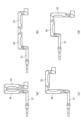
- 1A to 1D are diagrams showing the movement of the arm of a robot according to an embodiment of the present invention, in which (a) is a stored state, (b) is a front state, (c) is a down state, and (d) is an up state.
- FIG. 2 is a diagram showing a state in which a load is placed on the robot according to the embodiment of the present invention.
- FIG. 11 is a diagram for explaining the operation of the robot according to the embodiment of the present invention, showing a state in which the robot is holding a case placed on the ground.
- FIG. 11 is a diagram for explaining the operation of the robot according to the embodiment of the present invention, showing a state in which the robot is holding a case.
- FIG. 11 is a diagram for explaining the operation of the robot according to the embodiment of the present invention, showing the operation of displaying products on a product shelf.
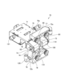
- FIG. 13 is a perspective view showing a modified example of the gripping portion of the robot according to the embodiment of the present invention.
- FIG. 13 is a front view showing a modified example of the gripping portion of the robot according to the embodiment of the present invention.
- FIG. 13 is a side view showing a modified example of the gripping portion of the robot according to the embodiment of the present invention.
- FIG. 13 is a bottom perspective view showing a modified example of the gripping portion of the robot according to the embodiment of the present invention.
- FIG. 10 is a cross-sectional view taken along line AA in FIG. 1A and 1B are diagrams showing the operation of a modified gripping unit of a robot according to an embodiment of the present invention, in which (a) shows a state in which a gripping object having a round cross section is gripped, (b) shows a state in which a flat gripping object is gripped from above, and (c) shows a state in which a flat gripping object is gripped.
- FIG. 1 is an oblique view of a robot according to an embodiment of the present invention
- FIG. 2 is an enlarged view showing the arm of a robot according to an embodiment of the present invention
- FIG. 3 is a diagram showing the movement of the arm of a robot according to an embodiment of the present invention, where (a) is a diagram showing a stored state, (b) is a diagram showing a front state, (c) is a diagram showing a down state, and (d) is a diagram showing an up state
- FIG. 4 is a diagram showing a robot according to an embodiment of the present invention with luggage placed thereon
- FIG. 1 is an oblique view of a robot according to an embodiment of the present invention
- FIG. 2 is an enlarged view showing the arm of a robot according to an embodiment of the present invention
- FIG. 3 is a diagram showing the movement of the arm of a robot according to an embodiment of the present invention, where (a) is a diagram showing a stored state, (b) is a diagram showing a
- FIG. 5 is a diagram explaining the operation of a robot according to an embodiment of the present invention, showing a state in which it is holding a case placed on the ground
- FIG. 6 is a diagram explaining the operation of a robot according to an embodiment of the present invention, showing a state in which it is holding a case
- FIG. 7 is a diagram explaining the operation of a robot according to an embodiment of the present invention.
- FIG. 8 is a perspective view showing a modified gripping part of a robot according to an embodiment of the present invention
- FIG. 9 is a front view showing a modified gripping part of a robot according to an embodiment of the present invention
- FIG. 10 is a side view showing a modified gripping part of a robot according to an embodiment of the present invention
- FIG. 8 is a perspective view showing a modified gripping part of a robot according to an embodiment of the present invention
- FIG. 9 is a front view showing a modified gripping part of a robot according to an embodiment of the present invention
- FIG. 10 is a
- FIG. 11 is a perspective view from the bottom showing a modified gripping part of a robot according to an embodiment of the present invention
- FIG. 12 is a cross-sectional view taken along line A-A in FIG. 9
- FIG. 13 is a diagram showing the operation of a modified gripping part of a robot according to an embodiment of the present invention, where (a) shows a state in which a gripping object having a round cross section is gripped, (b) shows a state in which a gripping object having a flat shape is gripped from above, and (c) shows a state in which a gripping object having a flat shape is gripped.
- the front-rear and up-down directions are defined as the directions of the arrows shown in FIG. 1
- the roll direction, pitch direction, and yaw direction are defined as the directions of rotation around the roll axis, pitch axis, and yaw axis shown in FIG. 2.
- the robot 1 includes a cart 10 with a running function, a gatepost 20 having a pair of pillars 21, 21 extending vertically from the cart 10 and a connecting portion 22 connecting the upper ends of the pair of pillars 21, 21, and a pair of arms 30 assembled so as to be movable along the extending direction of the pillars 21.
- the cart unit 10 has multiple wheels 11 and is configured to be self-propelled by a running device having a drive motor, control device, braking device, etc. (not shown).
- the robot 1 in this embodiment is self-propelled by the cart unit 10, and can move by itself to a position up to a product shelf where products are to be replenished or within a warehouse where products are stocked.
- the cart section 10 has a flat box-shaped cart body 12, which houses the drive motor, control device, braking device, and the like.
- the top surface 13 of the cart body 12 is formed flat and can be used as a loading space on which products and cases can be placed.
- a gatepost 20 stands vertically (up and down) at the rear corner of the top surface 13 of the cart body 12.
- the gatepost 20 is formed in a gate shape with a pair of pillars 21, 21 standing vertically from the top surface 13 of the cart body 12 and a connecting portion 22 that connects the upper ends of the pillars 21, 21 to each other.
- the arm 30 (first arm member 30a, second arm member 30b) described below is attached to the front side of the pillar 21.
- the pillar 21 is equipped with a movement mechanism (not shown), and the arm 30 is assembled so that it can be moved in the vertical direction of the pillar 21 by this movement mechanism.
- the movement mechanism can use various conventionally known configurations as long as it can move the arm 30 along the vertical direction of the pillar 21, but it is preferable for it to be configured, for example, by a drive motor and a circular belt member that can be rotated by the drive motor.
- flanges 23 are formed on the opposing side surfaces of the pillars 21, protruding from one pillar 21 toward the other pillar 21 at a specified interval.
- the length of the flanges 23 along the opposing direction is formed to be sufficient to hold the case on the flanges 23 between the pillars 21, and a specified gap is formed between the flanges 23.
- the connecting part 22 is provided with a first imaging unit 40 in approximately the center.
- the first imaging unit 40 can be any of various conventionally known cameras.
- the first imaging unit 40 can capture an image in front of the robot 1 according to this embodiment.
- a spherical camera capable of 360° imaging is preferably used as the first imaging unit 40.
- the arm portion 30 has a first arm member 30a and a second arm member 30b that are respectively attached to a pair of pillar portions 21, 21. Since the first arm member 30a and the second arm member 30b are members each having a similar configuration, the following explanation will focus on the first arm member 30a, and a detailed explanation of the second arm member 30b will be omitted.
- the first arm member 30a comprises a base end 31 movably attached to the pillar portion 21, a first arm portion 33 rotatably attached to the tip of the base end 31 via a first joint portion 32, a second arm portion 35 rotatably attached to the tip of the first arm portion 33 via a second joint portion 34, and a third arm portion 37 rotatably attached to the tip of the second arm portion 35 via a third joint portion 36, and the tip of the third arm portion 37 comprises a grip portion 39 rotatably attached to the tip of the third arm portion 37 via a fourth joint portion 38.
- the base end 31 is attached to the column 21 at its base end so as to be movable up and down, and the first joint 32 is attached above the tip end.
- the base end of the first joint 32 is attached to the base end 31 so as to be rotatable in the yaw direction a, and the tip end has a first arm 33 attached thereto so as to be rotatable in the pitch direction b via a first shaft 32a.
- the first joint 32 rotates in the yaw direction a and pitch direction b described above by a motor (not shown).
- the first arm 33 and the second arm 35 are long box-shaped members of roughly the same shape, with a first axis 32a and a second axis 34a, and a third axis 34b and a fourth axis 36a formed at both ends of each.
- the tip side of the first arm 33 and the base side of the second arm 35 are attached to the second joint 34, and are attached so as to be freely rotatable in the pitch direction b via the second axis 34a and the third axis 34b.
- the third arm 37 is a long box-shaped member similar to the first arm 33 and the second arm 35, but the base end forms a curved portion that curves upward, and the third joint 36, which has a shape similar to the first joint 32 described above, is attached to the upper surface of the curved portion.
- the base end of the third joint 36 is attached to the second arm 35 via the fourth shaft 36a so as to be rotatable in the pitch direction b, and the tip end is assembled to the third arm 37 so as to be rotatable in the yaw direction a.
- a second imaging unit 41 (for the second arm member 30b, a third imaging unit 42) is attached to the side of the curved portion of the third arm 37.
- the second imaging unit 41 is attached detachably and can be attached to any position on the arm 30, not just the side of the curved portion.
- a holding surface 50 is formed on the opposing surfaces of the first arm member 30a and the second arm member 30b of the third arm portion 37.
- the holding surface 50 is a portion used when the first arm member 30a and the second arm member 30b hold a case or the like as described below, and it is preferable that a slit shape is formed in the holding surface 50 or that an elastic material is attached to prevent the case or the like from falling out.
- a gripper 39 is attached to the tip of the third arm 37 via a fourth joint 38.
- the base end of the fourth joint 38 is attached to the tip of the third arm 37 so as to be rotatable in the roll direction c, and the tip is attached to the gripper 39 via a fifth shaft 38a so as to be rotatable in the pitch direction b.
- the gripper 39 is also attached to the sixth shaft 38b so as to be rotatable in the yaw direction a.
- the gripping section 39 has a pair of gripping claws 61, 61 that rotate around the base end, and the tip ends are assembled so that they can move toward or away from each other.
- the tips of the gripping claws 61 can be rotated in a direction that brings them closer together to grip a product or other object to be gripped, and can be rotated in a direction that moves them away from each other to release the gripped object.
- the arm 30 When the arm 30 is configured in this manner and moved around a warehouse or on a product shelf, the first arm 33 and the second arm 35 are brought close to each other as shown in FIG. 3(a) and arranged so as to be approximately parallel to the pillar 21, so that the arm 30 can be stored compactly without protruding far from the robot 1.
- the first arm 33 and the second arm 35 are extended to the front position horizontal to the ground, making it easier to take out a product that is far away. If the product is located in a high or low position, the height of the base end 31 of the arm 30 can be adjusted along the pillar 21, and the first arm 33 and the second arm 35 can be arranged to cross each other as shown in FIG. 3(c) or FIG. 3(d), making it possible to easily take out the product.
- the load on the root axis of each of the first to third arms 33, 35, and 37 can be reduced because of the structure using the parallel links vertically.
- top surface 13 of the cart 10 is formed as a flat loading surface, it is possible to stack cases B and the like on the cart 10 for transport, as shown in Figure 4, and the space between the pillars 21, 21 of the gatepost 20 can also be used as loading space.
- the pillars 21 are formed with flanges 23, so that trays T, cases B, etc. can be placed between the pillars 21 as shown in FIG. 5.
- the robot 1 according to this embodiment does not have shelves or the like between the pillars 21, 21, it is possible for the first imaging unit 40 attached to the connecting portion 22 of the gatepost 20 to clearly capture images of the placement surface of the upper surface 13 of the cart 10 and the state of the trays T and cases B held between the flanges 23.
- the robot 1 is provided with a first arm member 30a and a second arm member 30b on each of the pillars 21, 21, and these first arm member 30a and second arm member 30b can move in the up-down and back-forth directions independently of each other, so that the range of tasks that can be performed can be expanded, such as by handling different products at the same time.
- the arms 30 of the robot 1 according to this embodiment are formed with holding surfaces 50, so that the case can be held and lifted by the holding surfaces 50 of the first arm member 30a and the second arm member 30b, as shown in Figures 5 and 6.
- the cart unit 10 is driven to move the robot 1 according to this embodiment to the vicinity of case B to be grasped.
- an image of case B to be grasped is taken by the first imaging unit 40, and the image data is subjected to image processing, etc., and the robot 1 is moved to the position of case B.
- the cart 10 is moved close to case B, and the arm 30 is extended, for example to the front state shown in FIG. 3(b).
- the base end 31 of the arm 30 is moved below the pillar 21 to a height where the third arm 37 of the arm 30 can embrace the side of case B.
- case B both sides of case B are sandwiched between the holding surfaces 50, 50 of the pair of arms 30.
- case B can be held more securely.
- the base end 31 of the arm 30 is raised along the pillar 21, so that the case B can be lifted, and the case B can be placed on the upper surface 13 of the cart 10 or on the flange 23 formed on the pillar 21 for transport.
- the arm unit 30 can be stored between the product shelves 60 as shown in FIG. 3(a), allowing the robot 1 according to this embodiment to move without interfering with the product shelves 60. After moving to the desired product shelf 60 position, the transported product G is displayed in a designated location on the product shelf 60.
- the first arm member 30a and the second arm member 30b can operate independently of each other, so that, as shown in FIG. 7, the first arm member 30a can display products on the upper level of the product shelf 60, and the second arm member 30b can simultaneously display products on the lower level.
- the first arm 33 and the second arm 35 can be stored and the third joint 36 can be rotated in the yaw direction a to display the products G.
- the gripping portion 39 is attached to the third arm 37 so as to be rotatable in the roll direction, pitch direction, and yaw direction, so that the products G can be freely displayed in any desired position.
- first arm member 30a and the second arm member 30b are equipped with the second imaging unit 41 and the third imaging unit 42, respectively, so that the first arm member 30a and the second arm member 30b can perform image processing independently, making it possible to display the products G more efficiently.
- the gripping portion 39 is described as having a pair of gripping claws 61, 61 that rotate around the base end and are assembled so that the tip end can move toward and away from each other. Below, however, modified examples of the gripping portion are described.
- the gripper 70 has a gripper body 71 and a pair of gripping claws 72a, 72b attached to the tip of the gripper body 71.
- the gripper body 71 is configured so that it can be attached to the fourth joint 38 via an attachment part (not shown) on the base end side.
- the gripper body 71 also has a storage recess 79 formed therein to prevent interference between the gripper body 71 and the second gripping claw 72b when the second gripping claw 72b described below rotates toward the base end side of the gripper body 71.
- a pair of inlets 121 are formed on the side of the gripper body 71 to connect to a supply port 120 described below.
- the pair of gripping claws 72a, 72b are rotatably attached to each other via a rotating shaft 73 of a claw drive motor 100 attached to the tip side of the gripper body 71.
- the claw drive motors 100 are provided corresponding to the pair of gripping claws 72a, 72b, respectively, and the rotating shafts 73 are arranged coaxially with each other.
- the first gripping claw 72a has a pivot hole 74 formed at its base end through which the pivot shaft 73 described above passes, and has an attachment/detachment means 80 attached to its tip end via a biasing means 90 described below.
- the first gripping claw 72a has a side wall 78 in which a pivot hole 74 is formed to be attached to the pivot shaft 73 of the claw drive motor 100, and a wall portion 77 extending in the width direction of the gripper body 71 from the tip of the side wall 78.
- a guide arm portion 110 that rotates coaxially with the pivot shaft 73, and the guide arm portion 110 is disposed approximately parallel to the side wall 78.
- the side wall 78 is formed with a long guide hole 76 that guides a supply port 120 that supplies negative pressure to the attachment/detachment means 80 described below, and a side piece 78a that extends approximately parallel to the side wall 78 is formed at the end of the wall portion 77 opposite the side wall 78, and a guide groove 75 that guides the attachment/detachment means 80 is formed in the side piece 78a.
- an attachment/detachment means 80 is attached to the inside surrounded by the wall portion 77, side wall 78, and side piece 78a of the first gripping claw 72a.
- the attachment/detachment means 80 is attached so as to be movable in the extension direction of the guide groove 75 and the guide hole 76.
- the attachment/detachment means 80 comprises an attachment/detachment means main body 81 that communicates with the supply port 120, and an attachment/detachment part 82 attached to the attachment/detachment means main body 81.
- the attachment/detachment means main body 81 is formed to be hollow inside, and by having this hollow internal passage, air can be sucked from the supply port 120 by a negative pressure pump 123 (described later) to generate negative pressure in the attachment/detachment part 82.
- the attachment/detachment part 82 is preferably a rubber member formed in a suction cup shape, and can be attached to the object to be grasped by the negative pressure, thereby adsorbing the object to the gripping claws 72a, 72b.
- multiple attachment/detachment sections 82 are formed along the width direction of the gripping claws 72a, 72b, and in this modified example, two attachment/detachment sections 82 are arranged for each of the gripping claws 72a, 72b. Furthermore, as shown in FIG. 8, an engagement protrusion 83 that engages with the guide groove 75 is formed on the surface of the attachment/detachment means main body 81 facing the side piece 78a.
- the attachment/detachment means 80 is held by a guide arm 110 at approximately the center in the width direction of the attachment/detachment means main body 81.
- a biasing means 90 is provided adjacent to the guide arm 110.
- the guide arm 110 has a guide arm base 111 that rotates coaxially with the rotation shaft 73 at the end opposite the rotation shaft 73 of the claw drive motor 100, a guide arm end 113 that engages with the attachment/detachment means main body 81, and a guide arm main body 112 that connects the guide arm base 111 and the guide arm end 113.
- a roughly U-shaped guide portion 114 is formed at the end 113 of the guide arm, and the attachment/detachment means main body 81 is attached so that it can move toward the opening of the guide portion 114 by engaging with the guide portion 114.
- the biasing means 90 arranged close to the guide arm 110 has an elastic member 91 that biases the detachment means main body 81 in the direction opposite to the direction toward the opening of the guide portion 114 described above. It is preferable that a pair of elastic members 91 are provided to sandwich the center of the detachment portion 82. By biasing the detachment means 80 in this way with a pair of elastic members 91, the orientation of the detachment portion 82 can be rotated a certain angle in the vertical direction in FIG. 12 according to the shape and orientation of the object to be grasped.
- the gripping unit 70 of this modified example is arranged so that the attachment/detachment means 80 can be moved by the biasing means 90 in the direction in which the attachment/detachment part 82 attaches and detaches the object to be gripped.
- This makes it possible to adjust the orientation of the attachment/detachment part 82 to an appropriate direction depending on the shape of the object to be gripped, thereby enabling proper gripping of the object to be gripped.
- a valve 122 is attached inside the gripper body 71, and the valve 122 can connect the negative pressure pump 123 to the inlet 121 and the supply port 120, or can release this connection.
- the valve 122 is arranged so that it can be opened and closed by a control unit (not shown). This makes it possible to select whether or not to generate the negative pressure generated by the negative pressure pump 123 in the detachable part 82.
- the operation of the gripping unit 70 according to this modified example will be described.
- the first gripping claw 72a and the second gripping claw 72b are rotated so that they are horizontal to the gripping unit main body 71, forming the gripping unit 70 in a flat shape.
- the second gripping claw 72b is accommodated in the accommodation recess 79 of the gripping unit main body 71, thereby preventing interference between the second gripping claw 72b and the gripping unit main body 71 and allowing the second gripping claw 72b to be rotated to a position horizontal to the gripping unit main body 71.
- the gripping part 70 By making the gripping part 70 flat in this way, it is possible to insert the gripping part 70 into a vertically narrow space such as a shelf board, and handle an object to be gripped that is placed on the shelf board. At this time, the detachable part 82 is positioned facing downward, so that the object to be gripped can be held by the gripping part 70 by adsorbing it from above, as shown in FIG. 13(b).
- the gripping unit 70 when grasping a box-shaped object placed on a shelf, the gripping unit 70 is inserted between the shelf and the object, and the object is attracted to and held from above, making it easy to move the object placed on the shelf.
- the pivot shaft 73 is rotated to rotate the first gripping claw 72a and the second gripping claw 72b.
- the first gripping claw 72a is rotated toward the upper side of the gripping body 71, and the second gripping claw 72b is rotated largely so that it is positioned in front of the gripping body 71, so that the first gripping claw 72a and the second gripping claw 72b are arranged in a V-shape with respect to each other, as shown in FIG. 11.
- first gripping claw 72a and the second gripping claw 72b By arranging the first gripping claw 72a and the second gripping claw 72b in this manner, it becomes possible to grip an object having a round cross section, for example, as shown in FIG. 13(a). Specifically, it becomes possible to easily handle beverages stored in cans or plastic bottles. In this case, it is possible to grip cans or plastic bottles that are lined up on a shelf, and it is also possible to remove cans or plastic bottles stored in a storage box from the storage box.
- the first gripping claw 72a and the second gripping claw 72b can rotate independently of each other about the rotation axis 73, so that the first gripping claw 72a and the second gripping claw 72b can be rotated at any angle relative to the gripping unit main body 71.
- FIG. 13(c) it is also possible to arrange the first gripping claw 72a and the second gripping claw 72b so that their openings face downward relative to the gripping unit main body 71.
- FIG. 13(c) it is possible to grasp the corners of a box-shaped object to be grasped.
- the gap between the shelf and the object to be grasped as shown in FIG. 13(b) is too narrow for the grasping part 70 to insert, it is possible to handle the object to be grasped by gripping the corners of the object as if biting them.
- the gripping unit 70 of this modified example formed in this manner holds the object to be gripped by adsorption using the detachable part 82, so that the posture of the object to be gripped can be changed by rotating the fourth joint part on the base end side of the gripping unit 70, making it possible to flexibly handle the object to be gripped in a narrow area.
- the angle of the first gripping claw 72a and the second gripping claw 72b, as well as the angle and position of the detachable part 82, can be adjusted to match the shape of the object to be gripped, making it possible to handle a wide variety of objects to be gripped.
- first gripping claw 72a and the second gripping claw 72b can rotate independently of each other, in addition to holding the object by suction with the detachable part 82, it is also possible to hold the object by gripping with the first gripping claw 72a and the second gripping claw 72b.
- the attachment/detachment means 80 is attached to the inside surrounded by the wall portion 77, side wall 78, and side piece 78a of the first gripping claw 72a and the second gripping claw 72b, and the first gripping claw 72a and the second gripping claw 72b are hollow, so it is possible to miniaturize the gripping portion 70 itself, and by using it as part of the path of the pneumatic system, it is possible to reduce the number of parts.
- the robot 1 captures an image of the state of the product shelf 60 using the first imaging unit 40.
- the captured image data is processed by a control device (not shown) built into the trolley unit 10, and information on products that are missing from the product shelf 60 is calculated.
- the trolley unit 10 is then controlled to travel and move to the warehouse, and the necessary products are placed on the top surface of the trolley unit 10.
- the necessary products are captured by the second imaging unit 41 and the third imaging unit 42 attached to the first arm member 30a and the second arm member 30b, and the image data can be processed, so that the gripper 39 can be controlled more precisely in the pick-and-place operation.
- the arm unit 30 can move up and down along the pillar 21, and the first joint unit, the second joint unit, and the third joint unit can rotate freely in the pitch direction and the yaw direction, so that products can be replenished at any height of the product shelf.
- the robot 1 according to the present embodiment has been described above with the gripping section 39 at the tip of the arm 30, but the member attached to the tip of the arm 30 is not limited to the gripping section 39, and may be, for example, an adsorption section that can adsorb a product by suction of air or the like.
- a pair of arms 30 are provided on each of the pillars 21 of the gatepost 20, but the arms 30 may be provided on only one of the pillars 21, or multiple arms 30 may be attached to one pillar 21.
- the first imaging unit 40 has been described with a spherical camera, but the camera may be attached so that it can rotate up and down, for example.
- the gripping section 70 described in the modified example has been described with the negative pressure pump 123 generating negative pressure in the detachable section 82 to adsorb the object to be grasped, but the detachable section is not limited to this, and the object to be grasped may be held by, for example, a magnet, electromagnet, or adhesive. It is clear from the claims that such modifications or improvements are also included within the technical scope of the present invention.
Landscapes
- Engineering & Computer Science (AREA)
- Robotics (AREA)
- Mechanical Engineering (AREA)
- Manipulator (AREA)
Priority Applications (1)
| Application Number | Priority Date | Filing Date | Title |
|---|---|---|---|
| JP2024565702A JPWO2024135223A1 (https=) | 2022-12-19 | 2023-11-24 |
Applications Claiming Priority (4)
| Application Number | Priority Date | Filing Date | Title |
|---|---|---|---|
| JP2022202040 | 2022-12-19 | ||
| JP2022-202040 | 2022-12-19 | ||
| JP2023021880 | 2023-02-15 | ||
| JP2023-021880 | 2023-02-15 |
Publications (1)
| Publication Number | Publication Date |
|---|---|
| WO2024135223A1 true WO2024135223A1 (ja) | 2024-06-27 |
Family
ID=91588212
Family Applications (1)
| Application Number | Title | Priority Date | Filing Date |
|---|---|---|---|
| PCT/JP2023/042168 Ceased WO2024135223A1 (ja) | 2022-12-19 | 2023-11-24 | ロボット及び把持部 |
Country Status (2)
| Country | Link |
|---|---|
| JP (1) | JPWO2024135223A1 (https=) |
| WO (1) | WO2024135223A1 (https=) |
Citations (3)
| Publication number | Priority date | Publication date | Assignee | Title |
|---|---|---|---|---|
| JPH029595A (ja) * | 1988-06-29 | 1990-01-12 | Matsushita Electric Ind Co Ltd | 部品装着機の把持装置 |
| JP2009215014A (ja) * | 2008-03-11 | 2009-09-24 | Ishikame Kogyo:Kk | 環状部材の内周面に圧着される吊上げ冶具 |
| WO2021125035A1 (ja) * | 2019-12-17 | 2021-06-24 | Thk株式会社 | ロボット |
-
2023
- 2023-11-24 JP JP2024565702A patent/JPWO2024135223A1/ja active Pending
- 2023-11-24 WO PCT/JP2023/042168 patent/WO2024135223A1/ja not_active Ceased
Patent Citations (3)
| Publication number | Priority date | Publication date | Assignee | Title |
|---|---|---|---|---|
| JPH029595A (ja) * | 1988-06-29 | 1990-01-12 | Matsushita Electric Ind Co Ltd | 部品装着機の把持装置 |
| JP2009215014A (ja) * | 2008-03-11 | 2009-09-24 | Ishikame Kogyo:Kk | 環状部材の内周面に圧着される吊上げ冶具 |
| WO2021125035A1 (ja) * | 2019-12-17 | 2021-06-24 | Thk株式会社 | ロボット |
Also Published As
| Publication number | Publication date |
|---|---|
| JPWO2024135223A1 (https=) | 2024-06-27 |
Similar Documents
| Publication | Publication Date | Title |
|---|---|---|
| US9187264B2 (en) | Apparatus, systems and methods for securing, loading and unloading parts using locking dunnage | |
| US20230062304A1 (en) | Systems, methods, and storage units for article transport and storage | |
| ES2910073T3 (es) | Robot multibrazo para tareas de preparación de pedidos complejas | |
| EP3953116B1 (en) | Product manipulation tool and method of retrieving a container | |
| WO2020057571A1 (zh) | 可移动式密集存拣装置、组合式仓储系统及其组装方法 | |
| JP7756243B2 (ja) | マルチモードロボットエンドエフェクタ | |
| EP4341174B1 (en) | A storage column module for coupling to a framework structure of an automated storage and retrieval system | |
| JP6656306B2 (ja) | 箱組立ておよび梱包システム並びにそのシステム用コントローラ | |
| TW201641232A (zh) | 機器人系統 | |
| KR20240089485A (ko) | 주문 처리 시스템 및 방법 | |
| JP4007204B2 (ja) | ロボットシステム | |
| WO2024135223A1 (ja) | ロボット及び把持部 | |
| WO2010096937A1 (en) | Apparatus, systems and methods for securing, loading and unloading parts using locking dunnage | |
| JPS61257829A (ja) | 物品パレタイジング用ロボツトシステム | |
| JPH03239487A (ja) | 視覚を備えた自動組立装置 | |
| CN223493303U (zh) | 一种双臂联动型物流搬运机器人 | |
| CN211332057U (zh) | 定位装配工装 | |
| JP7689738B2 (ja) | 卵容器積込みシステム | |
| CN216996057U (zh) | 一种全向移动升降式搬运机器人 | |
| CN110977381A (zh) | 定位装配工装及方法 | |
| JP2025530729A (ja) | エンドツーエンド自動フルフィルメントセンターシステムおよび方法 | |
| JP7423194B2 (ja) | モバイル型の収容装置、及びそれを用いる配達方法 | |
| JP7339762B2 (ja) | モバイル型の収容装置、及びロボット制御方法 | |
| US20260109050A1 (en) | Open container gripping apparatuses and methods for handling open containers | |
| JP7541237B2 (ja) | 無人搬送車 |
Legal Events
| Date | Code | Title | Description |
|---|---|---|---|
| 121 | Ep: the epo has been informed by wipo that ep was designated in this application |
Ref document number: 23906592 Country of ref document: EP Kind code of ref document: A1 |
|
| WWE | Wipo information: entry into national phase |
Ref document number: 2024565702 Country of ref document: JP |
|
| NENP | Non-entry into the national phase |
Ref country code: DE |
|
| 122 | Ep: pct application non-entry in european phase |
Ref document number: 23906592 Country of ref document: EP Kind code of ref document: A1 |