WO2024135166A1 - 積層体及び積層体の製造方法 - Google Patents
積層体及び積層体の製造方法 Download PDFInfo
- Publication number
- WO2024135166A1 WO2024135166A1 PCT/JP2023/041025 JP2023041025W WO2024135166A1 WO 2024135166 A1 WO2024135166 A1 WO 2024135166A1 JP 2023041025 W JP2023041025 W JP 2023041025W WO 2024135166 A1 WO2024135166 A1 WO 2024135166A1
- Authority
- WO
- WIPO (PCT)
- Prior art keywords
- resin
- layer
- conductive layer
- laminate
- adhesive
- Prior art date
- Legal status (The legal status is an assumption and is not a legal conclusion. Google has not performed a legal analysis and makes no representation as to the accuracy of the status listed.)
- Ceased
Links
Images


Classifications
-
- B—PERFORMING OPERATIONS; TRANSPORTING
- B32—LAYERED PRODUCTS
- B32B—LAYERED PRODUCTS, i.e. PRODUCTS BUILT-UP OF STRATA OF FLAT OR NON-FLAT, e.g. CELLULAR OR HONEYCOMB, FORM
- B32B27/00—Layered products comprising a layer of synthetic resin
-
- B—PERFORMING OPERATIONS; TRANSPORTING
- B32—LAYERED PRODUCTS
- B32B—LAYERED PRODUCTS, i.e. PRODUCTS BUILT-UP OF STRATA OF FLAT OR NON-FLAT, e.g. CELLULAR OR HONEYCOMB, FORM
- B32B27/00—Layered products comprising a layer of synthetic resin
- B32B27/38—Layered products comprising a layer of synthetic resin comprising epoxy resins
-
- B—PERFORMING OPERATIONS; TRANSPORTING
- B29—WORKING OF PLASTICS; WORKING OF SUBSTANCES IN A PLASTIC STATE IN GENERAL
- B29C—SHAPING OR JOINING OF PLASTICS; SHAPING OF MATERIAL IN A PLASTIC STATE, NOT OTHERWISE PROVIDED FOR; AFTER-TREATMENT OF THE SHAPED PRODUCTS, e.g. REPAIRING
- B29C65/00—Joining or sealing of preformed parts, e.g. welding of plastics materials; Apparatus therefor
- B29C65/48—Joining or sealing of preformed parts, e.g. welding of plastics materials; Apparatus therefor using adhesives, i.e. using supplementary joining material; solvent bonding
- B29C65/4805—Joining or sealing of preformed parts, e.g. welding of plastics materials; Apparatus therefor using adhesives, i.e. using supplementary joining material; solvent bonding characterised by the type of adhesives
- B29C65/481—Non-reactive adhesives, e.g. physically hardening adhesives
- B29C65/4815—Hot melt adhesives, e.g. thermoplastic adhesives
-
- B—PERFORMING OPERATIONS; TRANSPORTING
- B29—WORKING OF PLASTICS; WORKING OF SUBSTANCES IN A PLASTIC STATE IN GENERAL
- B29C—SHAPING OR JOINING OF PLASTICS; SHAPING OF MATERIAL IN A PLASTIC STATE, NOT OTHERWISE PROVIDED FOR; AFTER-TREATMENT OF THE SHAPED PRODUCTS, e.g. REPAIRING
- B29C65/00—Joining or sealing of preformed parts, e.g. welding of plastics materials; Apparatus therefor
- B29C65/48—Joining or sealing of preformed parts, e.g. welding of plastics materials; Apparatus therefor using adhesives, i.e. using supplementary joining material; solvent bonding
- B29C65/486—Joining or sealing of preformed parts, e.g. welding of plastics materials; Apparatus therefor using adhesives, i.e. using supplementary joining material; solvent bonding characterised by their physical form being non-liquid, e.g. in the form of granules or powders
-
- B—PERFORMING OPERATIONS; TRANSPORTING
- B29—WORKING OF PLASTICS; WORKING OF SUBSTANCES IN A PLASTIC STATE IN GENERAL
- B29C—SHAPING OR JOINING OF PLASTICS; SHAPING OF MATERIAL IN A PLASTIC STATE, NOT OTHERWISE PROVIDED FOR; AFTER-TREATMENT OF THE SHAPED PRODUCTS, e.g. REPAIRING
- B29C65/00—Joining or sealing of preformed parts, e.g. welding of plastics materials; Apparatus therefor
- B29C65/48—Joining or sealing of preformed parts, e.g. welding of plastics materials; Apparatus therefor using adhesives, i.e. using supplementary joining material; solvent bonding
- B29C65/50—Joining or sealing of preformed parts, e.g. welding of plastics materials; Apparatus therefor using adhesives, i.e. using supplementary joining material; solvent bonding using adhesive tape, e.g. thermoplastic tape; using threads or the like
- B29C65/5057—Joining or sealing of preformed parts, e.g. welding of plastics materials; Apparatus therefor using adhesives, i.e. using supplementary joining material; solvent bonding using adhesive tape, e.g. thermoplastic tape; using threads or the like positioned between the surfaces to be joined
-
- B—PERFORMING OPERATIONS; TRANSPORTING
- B29—WORKING OF PLASTICS; WORKING OF SUBSTANCES IN A PLASTIC STATE IN GENERAL
- B29C—SHAPING OR JOINING OF PLASTICS; SHAPING OF MATERIAL IN A PLASTIC STATE, NOT OTHERWISE PROVIDED FOR; AFTER-TREATMENT OF THE SHAPED PRODUCTS, e.g. REPAIRING
- B29C66/00—General aspects of processes or apparatus for joining preformed parts
- B29C66/01—General aspects dealing with the joint area or with the area to be joined
- B29C66/05—Particular design of joint configurations
- B29C66/10—Particular design of joint configurations particular design of the joint cross-sections
- B29C66/11—Joint cross-sections comprising a single joint-segment, i.e. one of the parts to be joined comprising a single joint-segment in the joint cross-section
- B29C66/112—Single lapped joints
- B29C66/1122—Single lap to lap joints, i.e. overlap joints
-
- B—PERFORMING OPERATIONS; TRANSPORTING
- B29—WORKING OF PLASTICS; WORKING OF SUBSTANCES IN A PLASTIC STATE IN GENERAL
- B29C—SHAPING OR JOINING OF PLASTICS; SHAPING OF MATERIAL IN A PLASTIC STATE, NOT OTHERWISE PROVIDED FOR; AFTER-TREATMENT OF THE SHAPED PRODUCTS, e.g. REPAIRING
- B29C66/00—General aspects of processes or apparatus for joining preformed parts
- B29C66/40—General aspects of joining substantially flat articles, e.g. plates, sheets or web-like materials; Making flat seams in tubular or hollow articles; Joining single elements to substantially flat surfaces
- B29C66/47—Joining single elements to sheets, plates or other substantially flat surfaces
- B29C66/472—Joining single elements to sheets, plates or other substantially flat surfaces said single elements being substantially flat
-
- B—PERFORMING OPERATIONS; TRANSPORTING
- B29—WORKING OF PLASTICS; WORKING OF SUBSTANCES IN A PLASTIC STATE IN GENERAL
- B29C—SHAPING OR JOINING OF PLASTICS; SHAPING OF MATERIAL IN A PLASTIC STATE, NOT OTHERWISE PROVIDED FOR; AFTER-TREATMENT OF THE SHAPED PRODUCTS, e.g. REPAIRING
- B29C66/00—General aspects of processes or apparatus for joining preformed parts
- B29C66/50—General aspects of joining tubular articles; General aspects of joining long products, i.e. bars or profiled elements; General aspects of joining single elements to tubular articles, hollow articles or bars; General aspects of joining several hollow-preforms to form hollow or tubular articles
- B29C66/51—Joining tubular articles, profiled elements or bars; Joining single elements to tubular articles, hollow articles or bars; Joining several hollow-preforms to form hollow or tubular articles
- B29C66/53—Joining single elements to tubular articles, hollow articles or bars
- B29C66/532—Joining single elements to the wall of tubular articles, hollow articles or bars
- B29C66/5326—Joining single elements to the wall of tubular articles, hollow articles or bars said single elements being substantially flat
-
- B—PERFORMING OPERATIONS; TRANSPORTING
- B29—WORKING OF PLASTICS; WORKING OF SUBSTANCES IN A PLASTIC STATE IN GENERAL
- B29C—SHAPING OR JOINING OF PLASTICS; SHAPING OF MATERIAL IN A PLASTIC STATE, NOT OTHERWISE PROVIDED FOR; AFTER-TREATMENT OF THE SHAPED PRODUCTS, e.g. REPAIRING
- B29C66/00—General aspects of processes or apparatus for joining preformed parts
- B29C66/50—General aspects of joining tubular articles; General aspects of joining long products, i.e. bars or profiled elements; General aspects of joining single elements to tubular articles, hollow articles or bars; General aspects of joining several hollow-preforms to form hollow or tubular articles
- B29C66/61—Joining from or joining on the inside
-
- B—PERFORMING OPERATIONS; TRANSPORTING
- B29—WORKING OF PLASTICS; WORKING OF SUBSTANCES IN A PLASTIC STATE IN GENERAL
- B29C—SHAPING OR JOINING OF PLASTICS; SHAPING OF MATERIAL IN A PLASTIC STATE, NOT OTHERWISE PROVIDED FOR; AFTER-TREATMENT OF THE SHAPED PRODUCTS, e.g. REPAIRING
- B29C66/00—General aspects of processes or apparatus for joining preformed parts
- B29C66/70—General aspects of processes or apparatus for joining preformed parts characterised by the composition, physical properties or the structure of the material of the parts to be joined; Joining with non-plastics material
- B29C66/71—General aspects of processes or apparatus for joining preformed parts characterised by the composition, physical properties or the structure of the material of the parts to be joined; Joining with non-plastics material characterised by the composition of the plastics material of the parts to be joined
-
- B—PERFORMING OPERATIONS; TRANSPORTING
- B29—WORKING OF PLASTICS; WORKING OF SUBSTANCES IN A PLASTIC STATE IN GENERAL
- B29C—SHAPING OR JOINING OF PLASTICS; SHAPING OF MATERIAL IN A PLASTIC STATE, NOT OTHERWISE PROVIDED FOR; AFTER-TREATMENT OF THE SHAPED PRODUCTS, e.g. REPAIRING
- B29C66/00—General aspects of processes or apparatus for joining preformed parts
- B29C66/70—General aspects of processes or apparatus for joining preformed parts characterised by the composition, physical properties or the structure of the material of the parts to be joined; Joining with non-plastics material
- B29C66/73—General aspects of processes or apparatus for joining preformed parts characterised by the composition, physical properties or the structure of the material of the parts to be joined; Joining with non-plastics material characterised by the intensive physical properties of the material of the parts to be joined, by the optical properties of the material of the parts to be joined, by the extensive physical properties of the parts to be joined, by the state of the material of the parts to be joined or by the material of the parts to be joined being a thermoplastic or a thermoset
- B29C66/737—General aspects of processes or apparatus for joining preformed parts characterised by the composition, physical properties or the structure of the material of the parts to be joined; Joining with non-plastics material characterised by the intensive physical properties of the material of the parts to be joined, by the optical properties of the material of the parts to be joined, by the extensive physical properties of the parts to be joined, by the state of the material of the parts to be joined or by the material of the parts to be joined being a thermoplastic or a thermoset characterised by the state of the material of the parts to be joined
- B29C66/7375—General aspects of processes or apparatus for joining preformed parts characterised by the composition, physical properties or the structure of the material of the parts to be joined; Joining with non-plastics material characterised by the intensive physical properties of the material of the parts to be joined, by the optical properties of the material of the parts to be joined, by the extensive physical properties of the parts to be joined, by the state of the material of the parts to be joined or by the material of the parts to be joined being a thermoplastic or a thermoset characterised by the state of the material of the parts to be joined uncured, partially cured or fully cured
- B29C66/73755—General aspects of processes or apparatus for joining preformed parts characterised by the composition, physical properties or the structure of the material of the parts to be joined; Joining with non-plastics material characterised by the intensive physical properties of the material of the parts to be joined, by the optical properties of the material of the parts to be joined, by the extensive physical properties of the parts to be joined, by the state of the material of the parts to be joined or by the material of the parts to be joined being a thermoplastic or a thermoset characterised by the state of the material of the parts to be joined uncured, partially cured or fully cured the to-be-joined area of at least one of the parts to be joined being fully cured, i.e. fully cross-linked, fully vulcanized
-
- B—PERFORMING OPERATIONS; TRANSPORTING
- B29—WORKING OF PLASTICS; WORKING OF SUBSTANCES IN A PLASTIC STATE IN GENERAL
- B29C—SHAPING OR JOINING OF PLASTICS; SHAPING OF MATERIAL IN A PLASTIC STATE, NOT OTHERWISE PROVIDED FOR; AFTER-TREATMENT OF THE SHAPED PRODUCTS, e.g. REPAIRING
- B29C66/00—General aspects of processes or apparatus for joining preformed parts
- B29C66/70—General aspects of processes or apparatus for joining preformed parts characterised by the composition, physical properties or the structure of the material of the parts to be joined; Joining with non-plastics material
- B29C66/73—General aspects of processes or apparatus for joining preformed parts characterised by the composition, physical properties or the structure of the material of the parts to be joined; Joining with non-plastics material characterised by the intensive physical properties of the material of the parts to be joined, by the optical properties of the material of the parts to be joined, by the extensive physical properties of the parts to be joined, by the state of the material of the parts to be joined or by the material of the parts to be joined being a thermoplastic or a thermoset
- B29C66/739—General aspects of processes or apparatus for joining preformed parts characterised by the composition, physical properties or the structure of the material of the parts to be joined; Joining with non-plastics material characterised by the intensive physical properties of the material of the parts to be joined, by the optical properties of the material of the parts to be joined, by the extensive physical properties of the parts to be joined, by the state of the material of the parts to be joined or by the material of the parts to be joined being a thermoplastic or a thermoset characterised by the material of the parts to be joined being a thermoplastic or a thermoset
- B29C66/7394—General aspects of processes or apparatus for joining preformed parts characterised by the composition, physical properties or the structure of the material of the parts to be joined; Joining with non-plastics material characterised by the intensive physical properties of the material of the parts to be joined, by the optical properties of the material of the parts to be joined, by the extensive physical properties of the parts to be joined, by the state of the material of the parts to be joined or by the material of the parts to be joined being a thermoplastic or a thermoset characterised by the material of the parts to be joined being a thermoplastic or a thermoset characterised by the material of at least one of the parts being a thermoset
-
- B—PERFORMING OPERATIONS; TRANSPORTING
- B29—WORKING OF PLASTICS; WORKING OF SUBSTANCES IN A PLASTIC STATE IN GENERAL
- B29C—SHAPING OR JOINING OF PLASTICS; SHAPING OF MATERIAL IN A PLASTIC STATE, NOT OTHERWISE PROVIDED FOR; AFTER-TREATMENT OF THE SHAPED PRODUCTS, e.g. REPAIRING
- B29C66/00—General aspects of processes or apparatus for joining preformed parts
- B29C66/90—Measuring or controlling the joining process
- B29C66/91—Measuring or controlling the joining process by measuring or controlling the temperature, the heat or the thermal flux
- B29C66/919—Measuring or controlling the joining process by measuring or controlling the temperature, the heat or the thermal flux characterised by specific temperature, heat or thermal flux values or ranges
-
- B—PERFORMING OPERATIONS; TRANSPORTING
- B29—WORKING OF PLASTICS; WORKING OF SUBSTANCES IN A PLASTIC STATE IN GENERAL
- B29C—SHAPING OR JOINING OF PLASTICS; SHAPING OF MATERIAL IN A PLASTIC STATE, NOT OTHERWISE PROVIDED FOR; AFTER-TREATMENT OF THE SHAPED PRODUCTS, e.g. REPAIRING
- B29C66/00—General aspects of processes or apparatus for joining preformed parts
- B29C66/90—Measuring or controlling the joining process
- B29C66/92—Measuring or controlling the joining process by measuring or controlling the pressure, the force, the mechanical power or the displacement of the joining tools
- B29C66/929—Measuring or controlling the joining process by measuring or controlling the pressure, the force, the mechanical power or the displacement of the joining tools characterized by specific pressure, force, mechanical power or displacement values or ranges
Definitions
- This disclosure relates to a laminate and a method for manufacturing the laminate.
- a power module (PM) mounted on a hybrid vehicle or the like includes a laminate (also called a housing) of a resin molded part and a metal.
- housings are manufactured by arranging a conductive layer and an insulating layer in a mold, and then injecting a resin into the mold to form a molding (hereinafter, also referred to as insert molding) (see Patent Document 1).
- a heat sink having elements and the like brazed thereto is attached to a housing used in a PM. From the viewpoint of improving manufacturing efficiency, it is desirable to simultaneously bond the heat sink to the housing and the elements, etc. to the heat sink. However, heat is applied to the housing when the elements, etc. are brazed to the heat sink.
- the present inventors have now discovered that in a housing manufactured by the conventional insert molding disclosed in Patent Document 1, the conductive layer is embedded in the resin layer, and therefore when the laminate is placed in a high-temperature environment, heated, etc., it is unable to fully alleviate the internal stress caused by the difference in linear expansion coefficients between the conductive layer and the resin layer, resulting in the generation of cracks and deformation of the conductive layer and resin layer, and therefore there is room for improvement in its thermal durability.
- the problem that one embodiment of the present disclosure aims to solve is to provide a laminate with excellent thermal durability, as well as a method for manufacturing the laminate.
- the first resin layer has a storage portion, the first conductive layer is disposed within the housing portion of the first resin layer;
- a laminate comprising an adhesive layer at least either between the first conductive layer and the insulating layer or between the insulating layer and the second conductive layer, the adhesive layer containing a solid bonding agent mainly composed of an amorphous thermoplastic resin which is at least one type selected from a thermoplastic epoxy resin and a phenoxy resin, the amorphous thermoplastic resin having an epoxy equivalent of 1,600 or more, or the amorphous thermoplastic resin does not contain an epoxy group, and the amorphous thermoplastic resin has a heat of fusion of 15 J/g or less.
- ⁇ 2> The laminate according to ⁇ 1>, wherein the storage portion includes a concave portion or an uneven portion.
- the first conductive layer, the insulating layer, and the second conductive layer are disposed in the housing portion of the first resin layer.
- ⁇ 4> The laminate according to ⁇ 1> or ⁇ 2>, wherein an area of the housing portion of the first resin layer is equal to or larger than an area of the first conductive layer.
- the insulating layer is further provided on a side of the second conductive layer opposite to the insulating layer,
- the adhesive layer is provided at least one between the first resin layer and the first conductive layer, and between the second conductive layer and the second resin layer.
- ⁇ 6> The laminate according to any one of ⁇ 1> to ⁇ 5>, wherein the first resin layer is a cured product of a resin composition containing a thermosetting resin.
- the thermosetting resin contains an unsaturated polyester.
- ⁇ 8> The laminate according to any one of ⁇ 1> to ⁇ 7>, wherein the first resin layer has a fixing portion that fixes the first conductive layer, the insulating layer, and the second conductive layer.
- a method for producing a laminate comprising: A method for producing a laminate, wherein the amorphous thermoplastic resin has an epoxy equivalent of 1,600 or more, or the amorphous thermoplastic resin does not contain an epoxy group and has
- ⁇ 10> The method for producing a laminate according to ⁇ 9>, wherein the heating and pressurizing are carried out under conditions of 100° C. to 400° C. and 0.01 MPa to 20 MPa.
- ⁇ 11> The method for producing a laminate according to ⁇ 9> or ⁇ 10>, wherein the solid bonding agent before melting has any shape selected from the group consisting of a film, a rod, a pellet, and a powder.
- FIG. 1 is a perspective view showing one embodiment of a laminate according to the present disclosure.
- FIG. 2 is a perspective view showing another embodiment of a laminate according to the present disclosure.
- FIG. 3 is a perspective view showing one embodiment of a laminate of the present disclosure.
- FIG. 4 is a cross-sectional view showing another embodiment of a laminate according to the present disclosure.
- FIG. 5 is a cross-sectional view showing another embodiment of a laminate according to the present disclosure.
- FIG. 6 is a perspective view showing one embodiment of a first resin layer included in the laminate of the present disclosure.
- FIG. 7 is a perspective view showing one embodiment of a first resin layer included in the laminate of the present disclosure.
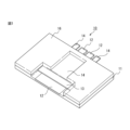
- FIG. 8 is a perspective view showing another embodiment of a laminate according to the present disclosure.
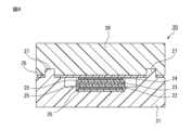
- FIG. 9 is a schematic cross-sectional view of a state in which a first member and a second member are bonded together via an adhesive layer containing a solid adhesive.
- step includes not only a step that is independent of other steps, but also a step that cannot be clearly distinguished from other steps as long as the purpose of the step is achieved.
- a numerical range indicated using "" includes the numerical values before and after "! as the minimum and maximum values, respectively.
- the upper or lower limit value described in one numerical range may be replaced with the upper or lower limit value of another numerical range described in stages.
- the upper or lower limit value of the numerical range may be replaced with a value shown in the examples.
- each component may contain multiple types of the corresponding substance.
- the content or amount of each component means the total content or amount of the multiple substances present in the composition, unless otherwise specified.
- the term "layer" includes cases where the layer is formed over the entire area when the area in which the layer exists is observed, as well as cases where the layer is formed over only a portion of the area.
- Adhesion means joining two adherends (objects to be bonded) together via an organic material such as a tape or adhesive (curable resin, thermoplastic resin, etc.).
- Welding means joining by utilizing entanglement and crystallization due to molecular diffusion that occurs during the process of contact pressure application and cooling of the surface of a thermoplastic resin or the like by heat, or by utilizing intermolecular interactions with the base material that occur during melting.
- the laminate of the present disclosure comprises, in this order, a first resin layer, a first conductive layer, an insulating layer, and a second conductive layer, the first resin layer having a accommodating portion, and the first conductive layer is disposed within the accommodating portion of the first resin layer.
- the laminate of the present disclosure has excellent thermal durability.
- the reason why the above effect is exhibited is not clear, but is presumed to be as follows.
- the laminate of the present disclosure can be manufactured by preparing each layer individually and laminating them, rather than by insert molding. Therefore, in a laminate manufactured by insert molding, the first conductive layer is embedded in the first resin layer and is completely adhered to the first resin layer, whereas in the laminate of the present disclosure, the first resin layer has a storage portion, so that the first conductive layer is not completely adhered to the first resin layer, and the internal stress generated during heating can be relaxed. It is presumed that this can suppress the occurrence of cracks and deformation of the conductive layer and the resin layer, thereby improving heat durability. Furthermore, the first resin layer has a housing portion, which is difficult to form by insert molding, and it is presumed that this improves thermal durability.
- the laminate of the present disclosure may further include a second resin layer on the side of the second conductive layer opposite the insulating layer.
- the laminate of the present disclosure comprises an adhesive layer at least one between the first conductive layer and the insulating layer and between the insulating layer and the second conductive layer, and may further optionally comprise an adhesive layer at least one between the first resin layer and the first conductive layer and between the second conductive layer and the second resin layer. From the viewpoint of thermal durability, the adhesive layer is preferably disposed within the housing portion of the first resin layer.
- the laminate of the present disclosure may include a heat sink on the surface of the first conductive layer facing the first resin layer or on the surface of the second conductive layer facing the second resin layer. From the viewpoint of thermal durability, the heat sink is preferably disposed within the housing portion of the first resin layer.
- the first resin layer has a housing portion, and the first conductive layer is disposed in the housing portion.
- the housing portion preferably includes a concave portion or an uneven portion.
- the housing portion including the concave and convex portions means that the housing portion includes concave and convex portions.
- the concave portions may be stepped.
- the first conductive layer, the insulating layer and the second conductive layer are preferably disposed within the housing portion of the first resin layer.
- the accommodation portion includes a stepped recessed portion
- the first conductive layer, the insulating layer and the second conductive layer may be accommodated in the same layer or in different layers.
- 3 to 5 show an embodiment in which a first conductive layer, an insulating layer and a second conductive layer are accommodated in different levels of a stepped recessed portion.
- the first resin layer may have one storage section, or may have two or more storage sections.
- Each of the accommodation portions 101 of the first resin layer 100 shown in FIG. 6 includes a concave portion 102A and a convex portion 102B.
- the first conductive layer 105 may be disposed in some of the accommodating portions as shown in FIG. 7, or the first conductive layer 105 may be disposed in all of the accommodating portions.
- the insulating layer and the second conductive layer do not need to be laminated on the first conductive layers arranged in all of the housing parts, but may be laminated on all of the first conductive layers arranged in the housing parts as shown in Fig. 8. In Fig. 8, the insulating layer is not shown, and the second conductive layer is indicated by the reference numeral 106.
- the area of the storage portion of the first resin layer is preferably equal to or larger than the area of the first conductive layer.
- the ratio of the area of the first conductive layer to the area of the storage portion of the first resin layer is preferably 1.01 or more. This makes it easy to arrange the first conductive layer in the storage portion of the first resin layer.
- the area ratio is preferably 2.00 or less. This tends to suppress the occurrence of positional deviation of the first conductive layer on the first resin layer.
- the size of the housing portion be appropriately changed depending on the size of the first conductive layer, the use of the laminate, etc.
- the area of the housing portion can be, for example, 1 cm 2 to 1000 cm 2 .
- the depth of the housing part is preferably at least equal to or greater than the thickness of the first conductive layer, more preferably equal to or greater than the sum of the thicknesses of the first conductive layer, the insulating layer, and the second conductive layer, even more preferably equal to or greater than the sum of the thicknesses of the first conductive layer, the insulating layer, the second conductive layer, and the adhesive layer, and particularly preferably equal to or greater than the sum of the thicknesses of the first conductive layer, the insulating layer, the second conductive layer, the adhesive layer, and the heat sink.
- the thickness of the housing part can be, for example, 0.1 mm to 100 mm.
- the depth of the housing portion may be less than the total thickness of the first conductive layer, the insulating layer, the second conductive layer, the adhesive layer, and the heat sink.
- the first resin layer is preferably a cured product of a resin composition containing a thermosetting resin.
- the type of thermosetting resin is not particularly limited as long as it has one or more functional groups in one molecule that can be used in a crosslinking reaction by heating.
- the functional group include an epoxy group, an acryloyl group, a methacryloyl group, a hydroxyl group, a vinyl group, a carboxyl group, an amino group, a maleimide group, an acid anhydride group, a thiol group, a thionyl group, an amide group, and an imide group.
- thermosetting resin examples include a phenol resin, an unsaturated imide resin, a cyanate resin, an isocyanate resin, a benzoxazine resin, an oxetane resin, an amino resin, an unsaturated polyester resin, an acrylic resin, a dicyclopentadiene resin, a silicone resin, a triazine resin, a melamine resin, a resorcinol resin, an epoxy resin, etc.
- the resin composition may contain one type of thermosetting resin alone or two or more types of thermosetting resins.
- Unsaturated polyesters can be obtained by polycondensation (esterification) of polyhydric alcohols with unsaturated polybasic acids, saturated polybasic acids, etc.
- the polyhydric alcohol is not particularly limited, and any conventionally known polyhydric alcohol can be used.
- polyhydric alcohols include ethylene glycol, propylene glycol, butanediol, diethylene glycol, dipropylene glycol, triethylene glycol, pentanediol, hexanediol, neopentanediol, hydrogenated bisphenol A, bisphenol A, glycerin, and the like. These may be used alone or in combination of two or more.
- the unsaturated polybasic acid is not particularly limited, and conventionally known acids can be used.
- the unsaturated polybasic acid include maleic anhydride, fumaric acid, citraconic acid, itaconic acid, etc. These can be used alone or in combination.
- the saturated polybasic acid is not particularly limited, and conventionally known acids can be used.
- Examples of the saturated polybasic acid include phthalic anhydride, isophthalic acid, terephthalic acid, HET acid, succinic acid, adipic acid, sebacic acid, tetrachlorophthalic anhydride, tetrabromophthalic anhydride, and endomethylenetetrahydrophthalic anhydride. These may be used alone or in combination of two or more.
- the unsaturated polyester may be one synthesized by a known method using the above-mentioned raw materials, or a commercially available product may be used.
- the unsaturated polyester can be obtained by polycondensing a polyhydric alcohol with an unsaturated polybasic acid, a saturated polybasic acid, or the like in an atmosphere of an inert gas such as nitrogen at a temperature of 140° C. to 230° C.
- the polycondensation reaction may be carried out under pressurized or reduced pressure conditions.
- a crosslinking agent and a catalyst may be used, if necessary.
- crosslinking agent examples include styrene monomer, diallyl phthalate monomer, diallyl phthalate prepolymer, methyl methacrylate, triallyl isocyanurate, etc. These may be used alone or in combination.
- catalyst examples include manganese acetate, dibutyltin oxide, stannous oxalate, zinc acetate, cobalt acetate, etc. These may be used alone or in combination of two or more.
- the number average molecular weight of the thermosetting resin is preferably 1,000 to 10,000, and more preferably 1,500 to 5,000.
- the number average molecular weight is a weight average molecular weight in terms of polystyrene measured by gel permeation chromatography (GPC).
- the content of the thermosetting resin relative to the total mass of the resin composition is preferably 10% by mass to 60% by mass, more preferably 20% by mass to 50% by mass, and even more preferably 20% by mass to 40% by mass.
- the resin composition may contain a thermoplastic resin, an elastomer, or the like.
- thermoplastic resins include polyimide resins, polyamideimide resins, polyamide resins, polyetherimide resins, polybenzoxazole resins, polybenzimidazole resins, polystyrene resins, acrylonitrile-butadiene-styrene copolymer resins, acrylonitrile-styrene copolymer resins, polyethylene resins, polypropylene resins, polyvinyl chloride resins, polyvinylidene chloride resins, polycarbonate resins, (meth)acrylic resins, polyester resins, polyacetal resins, and polyphenylene sulfide resins (PPS).
- the elastomer include silicone rubber, styrene butadiene rubber (SBR), nitrile rubber (NBR), and urethane rubber.
- the resin composition may contain various additives such as a curing agent, a curing accelerator, a filler, a release agent, a flame retardant, a colorant, a plasticizer, a silane coupling agent, an anti-rust agent, a copper damage inhibitor, a reducing agent, an antioxidant, a tackifying resin, an ultraviolet absorber, an antifoaming agent, a leveling adjuster, and a solvent.
- additives such as a curing agent, a curing accelerator, a filler, a release agent, a flame retardant, a colorant, a plasticizer, a silane coupling agent, an anti-rust agent, a copper damage inhibitor, a reducing agent, an antioxidant, a tackifying resin, an ultraviolet absorber, an antifoaming agent, a leveling adjuster, and a solvent.
- the first resin layer may have a fixing portion that fixes the first conductive layer, the insulating layer, and the second conductive layer.
- the first resin layer and the second resin layer may have either an insertion portion or an opening.
- the first resin layer and the second resin layer can be fitted together by inserting the insertion portion into the opening.
- the first conductive layer and the second conductive layer may include at least one of a metal and a metal oxide.
- the metal include silver, gold, copper, palladium, platinum, titanium, chromium, nickel, aluminum, zirconium, tungsten, vanadium, rhodium, iridium, and alloys thereof.
- metal oxides include zinc oxide (ZnO), tin oxide (SnO 2 ), indium tin oxide (ITO), aluminum oxide (Al 2 O 3 ), and titanium oxide (TiO 2 ).
- the average thickness of the first conductive layer and the second conductive layer can be appropriately set depending on the application, etc. In consideration of ease of arrangement in the concave or convex portion of the first resin layer, it is preferably 0.1 mm to 10 mm. In the present disclosure, the average thickness is determined by measuring the thickness at two points on a layer with a measuring device and averaging these values.
- the materials contained in the first conductive layer and the second conductive layer, the average thickness of the layers, etc. may be the same or different.
- the insulating layer is preferably a cured product of a resin composition containing an insulating resin.
- insulating resins include thermoplastic resins, thermosetting resins, and curable resins such as photocurable resins.
- the photocurable resin may be any resin having one or more unsaturated bonds in one molecule that undergo a crosslinking reaction when exposed to light.
- Specific examples of the photocurable resin include acrylic resin, urethane resin, polyester resin, polyether resin, epoxy resin, polybutadiene resin, polyimide resin, polyamide resin, silicone resin, and fluororesin.
- the thermoplastic resin and the thermosetting resin have been described above, so a description thereof will be omitted here.
- the resin composition may contain various additives such as a curing agent, a curing accelerator, a photopolymerization initiator, a filler, a release agent, a flame retardant, a colorant, a plasticizer, a silane coupling agent, an anti-rust agent, a copper damage inhibitor, a reducing agent, an antioxidant, a tackifying resin, an ultraviolet absorber, an antifoaming agent, a leveling adjuster, and a solvent.
- additives such as a curing agent, a curing accelerator, a photopolymerization initiator, a filler, a release agent, a flame retardant, a colorant, a plasticizer, a silane coupling agent, an anti-rust agent, a copper damage inhibitor, a reducing agent, an antioxidant, a tackifying resin, an ultraviolet absorber, an antifoaming agent, a leveling adjuster, and a solvent.
- the average thickness of the insulating layer can be set appropriately depending on the application, etc. Considering the ease of placement on the concave or convex portions of the first resin layer, it is preferable that the thickness is 0.01 mm to 10 mm.
- the laminate of the present disclosure may further include a second resin layer on the opposite side of the second conductive layer to the insulating layer.
- the second resin layer may have a concave portion, a convex portion, or an uneven portion.
- the concave portion, the convex portion, or the uneven portion provided in the second resin layer may be provided to correspond to the shape of the second conductive layer.
- a recess may be provided in the second resin layer to match the shape of the second conductive layer.
- the area of the recess in the second resin layer is preferably equal to or greater than the area of the second conductive layer.
- a convex portion may be provided in the second resin layer at a position corresponding to the second conductive layer. The number of convex portions may be one or more than two.
- the second resin layer is preferably a cured product of a resin composition containing a thermosetting resin.
- the thermosetting resin and the resin composition have been described above, so a description thereof will be omitted here.
- the second resin layer may have a fixing portion that fixes the first conductive layer, the insulating layer, and the second conductive layer.
- the laminate of the present disclosure includes an adhesive layer at least one between the first conductive layer and the insulating layer, between the insulating layer and the second conductive layer, between the first resin layer and the first conductive layer, and between the second conductive layer and the second resin layer.
- the first resin layer and the second resin layer may be bonded to each other by adjusting the size of an adhesive layer provided between any of the layers.
- the adhesive layer may include an intermediate layer of an insulator, and in that case, the adhesive layer is preferably a three-layer structure of a bonding material, an intermediate layer, and a bonding material from the viewpoint of adhesiveness and insulating properties.
- the intermediate layer of an insulator defects such as insulating pinholes are less likely to occur, and insulating properties can be improved.
- the resin for the intermediate layer examples include polyimide resin, polyamideimide resin, polyamide resin, polyetherimide resin, polybenzoxazole resin, polybenzimidazole resin, polystyrene resin, acrylonitrile-butadiene-styrene copolymer resin, acrylonitrile-styrene copolymer resin, polyethylene resin, polypropylene resin, polyvinyl chloride resin, polyvinylidene chloride resin, polycarbonate resin, (meth)acrylic resin, polyester resin, polyacetal resin, polyphenylene sulfide resin (PPS), phenol resin, and the like.
- the adhesive layer contains a solid bonding agent, which can suppress changes in thickness of the adhesive layer when laminating the first conductive layer, the adhesive layer, the insulating layer, and the like on the surface of the first resin layer, and can suppress changes in the distance between the first conductive layer and the insulating layer, the distance between the first conductive layer and the second conductive layer, the distance between the second conductive layer and the insulating layer, and the like.
- the solid bonding agent is mainly composed of at least one amorphous thermoplastic resin selected from a thermoplastic epoxy resin and a phenoxy resin, and the amorphous thermoplastic resin has an epoxy equivalent of 1,600 or more, or the amorphous thermoplastic resin does not contain an epoxy group, and the heat of fusion of the amorphous thermoplastic resin is 15 J/g or less.
- solid in the solid adhesive means that it is solid at room temperature, i.e., that it has no fluidity when it is not pressurized at 23°C. It is desirable that the solid adhesive be able to retain its shape without deformation for 30 days or more when it is not pressurized at 23°C, and furthermore, that it has the property of not changing quality.
- the "main component” refers to the component that is contained most abundantly among the resin components in the solid bonding agent and that accounts for 50% by mass or more of the resin components in the solid bonding agent.
- the solid bonding agent preferably contains 50% by mass or more of the resin component, more preferably 70% by mass or more, even more preferably 80% by mass or more, and particularly preferably 90% by mass or more.
- an amorphous resin is a resin that has a melting point (Tm) but does not have a clear endothermic peak associated with melting or has a very small endothermic peak when measured using a differential scanning calorimeter (DSC).
- Tm melting point
- DSC differential scanning calorimeter
- the heat of fusion is calculated from the area of the endothermic peak in DSC and the mass of the thermoplastic resin component.
- inorganic fillers or the like are contained in the solid bonding agent, the heat of fusion is calculated from the mass of the resin component excluding the inorganic filler.
- an amorphous thermoplastic resin refers to a resin having properties that can be measured by the following procedure. 2 to 10 mg of a sample is weighed out, placed in an aluminum pan, and heated from 23°C to 200°C or higher at 10°C/min using a DSC (Rigaku Corporation DSC8231) to obtain a DSC curve. The area of the endothermic peak upon melting obtained from the DSC curve is then used to calculate the heat of fusion from the weighed value. If the heat of fusion is 15 J/g or less, the resin is deemed to be an amorphous thermoplastic resin.
- the content of the amorphous thermoplastic resin is preferably 60% by mass or more, more preferably 70% by mass or more, even more preferably 80% by mass or more, and most preferably 90% by mass or more of the resin components in the solid bonding agent.
- the heat of fusion is 15 J/g or less, preferably 11 J/g or less, more preferably 7 J/g or less, even more preferably 4 J/g or less, and most preferably the endothermic peak upon melting is below the detection limit.
- the epoxy equivalent is 1,600 or more, preferably 2,000 or more, more preferably 5,000 or more, even more preferably 9,000 or more, and most preferably above the detection limit so that epoxy groups are substantially not detectable.
- this solid adhesive By using this solid adhesive, the sudden drop in viscosity seen with conventional hot melt adhesives does not occur when heated, and the adhesive does not reach a low viscosity state (0.001 to 100 Pa ⁇ s) even in high temperature ranges exceeding 200°C. Therefore, the solid adhesive does not flow out of the laminate even in a molten state, and the thickness of the adhesive layer can be stably secured, making it possible to stably obtain high adhesive strength.
- the epoxy equivalent in this disclosure (the mass of the resin containing 1 mole of epoxy groups) is the epoxy equivalent value of the thermoplastic epoxy resin or phenoxy resin component contained in the solid adhesive before bonding, and is a value (unit: g/eq.) measured by the method specified in JIS K 7236:2001. Specifically, the epoxy equivalent of the resin is measured using a potentiometric titration device, using cyclohexanone as the solvent, adding tetraethylammonium bromide acetate solution to the resin, and using a 0.1 mol/L perchloric acid-acetic acid solution. For solvent-diluted products (resin varnishes), the value is calculated as a solids equivalent value based on the non-volatile content.
- the epoxy equivalent of a mixture of two or more resins can also be calculated from the content and epoxy equivalent of each resin.
- the melting point of the amorphous thermoplastic resin which is the main component of the solid adhesive, is preferably 50°C to 400°C, more preferably 60°C to 350°C, and even more preferably 70°C to 300°C.
- the melting point of the amorphous thermoplastic resin means the temperature at which it substantially softens from a solid and acquires thermoplastic properties, making it possible to melt and bond.
- thermosetting adhesives In conventional joints containing thermosetting adhesives, it is difficult to disassemble the joints, and it is difficult to separate and recycle the different materials that make up the joints (i.e., poor recyclability). In addition, when a thermosetting adhesive is used, it is difficult to reattach the joints when there is a misalignment of the joint during the joint manufacturing process, or when the adherends are defective and need to be replaced (i.e., poor repairability), and it lacks convenience. On the other hand, the solid adhesive can be softened and melted by heat, and the two adherends can be easily separated, making it highly recyclable. In addition, because the solid adhesive is thermoplastic, it can be reversibly softened, melted, and hardened (solidified), and is therefore highly repairable.
- the thermoplastic epoxy resin is preferably a polymer of (a) a bifunctional epoxy resin monomer or oligomer and (b) a bifunctional compound having two identical or different functional groups selected from the group consisting of a phenolic hydroxyl group, a carboxyl group, a mercapto group, an isocyanate group, and a cyanate ester group.
- the (a) bifunctional epoxy resin monomer or oligomer refers to an epoxy resin monomer or oligomer having two epoxy groups in the molecule.
- Examples of the (a) bifunctional epoxy resin monomer or oligomer include bisphenol A type epoxy resin, bisphenol F type epoxy resin, bifunctional phenol novolac type epoxy resin, bisphenol AD type epoxy resin, biphenyl type epoxy resin, bifunctional naphthalene type epoxy resin, bifunctional alicyclic epoxy resin, bifunctional glycidyl ester type epoxy resin (e.g. diglycidyl phthalate, diglycidyl tetrahydrophthalate, dimer acid diglycidyl ester, etc.), bifunctional glycidyl amine type epoxy resin (e.g.
- bifunctional heterocyclic epoxy resin bifunctional diarylsulfone type epoxy resin, hydroquinone type epoxy resin (e.g. hydroquinone diglycidyl ether, etc.), , 2,5-di-tert-butylhydroquinone diglycidyl ether, resorcin diglycidyl ether, etc.), bifunctional alkylene glycidyl ether compounds (for example butanediol diglycidyl ether, butenediol diglycidyl ether, butynediol diglycidyl ether, etc.), bifunctional glycidyl group-containing hydantoin compounds (for example 1,3-diglycidyl-5,5-dialkylhydantoin, 1-glycidyl-3-(glycidoxyalkyl)-5,5-dialkylhydantoin, etc.), bifunctional g
- bifunctional compounds having a phenolic hydroxyl group in (b) above include mononuclear aromatic dihydroxy compounds having one benzene ring, such as catechol, resorcin, and hydroquinone; bisphenol compounds such as bis(4-hydroxyphenyl)propane (bisphenol A), bis(4-hydroxyphenyl)methane (bisphenol F), and bis(4-hydroxyphenyl)ethane (bisphenol AD); compounds having a condensed ring, such as dihydroxynaphthalene; bifunctional phenol compounds having an allyl group introduced, such as diallyl resorcin, diallyl bisphenol A, and triallyl dihydroxybiphenyl; and dibutyl bisphenol A.
- mononuclear aromatic dihydroxy compounds having one benzene ring such as catechol, resorcin, and hydroquinone
- bisphenol compounds such as bis(4-hydroxyphenyl)propane (bisphenol A), bis(4-hydroxyphenyl)
- Examples of the (b) bifunctional compound having a carboxyl group include adipic acid, succinic acid, malonic acid, cyclohexanedicarboxylic acid, phthalic acid, isophthalic acid, and terephthalic acid.
- Examples of the (b) bifunctional compound having a mercapto group include ethylene glycol bisthioglycolate and ethylene glycol bisthiopropionate.
- Examples of the (b) bifunctional compound having an isocyanate group include diphenylmethane diisocyanate (MDI), isophorone diisocyanate (IPDI), hexamethylene diisocyanate (HMDI), and tolylene diisocyanate (TDI).
- MDI diphenylmethane diisocyanate
- IPDI isophorone diisocyanate
- HMDI hexamethylene diisocyanate
- TDI tolylene diisocyanate
- Examples of the bifunctional compound having a cyanate ester group (b) include 2,2-bis(4-cyanatophenyl)propane, 1,1-bis(4-cyanatophenyl)ethane, and bis(4-cyanatophenyl)methane.
- bifunctional compounds having a phenolic hydroxyl group are preferred because they can form thermoplastic polymers with suitable properties
- bifunctional compounds having two phenolic hydroxyl groups and a bisphenol structure or a biphenyl structure are preferred from the viewpoints of heat resistance and adhesiveness
- bisphenol A, bisphenol F and bisphenol S are preferred from the viewpoints of heat resistance and cost.
- the polymer obtained by polymerization of (a) and (b) has a paraphenylene structure and an ether bond as the main skeleton, a main chain in which they are connected by an alkylene group, and a structure in which hydroxyl groups generated by polyaddition are arranged in the side chain.
- the linear structure resulting from the main skeleton having the paraphenylene structure and the ether bond can increase the mechanical strength of the polymer after polymerization, and the hydroxyl groups arranged in the side chain can improve the adhesion to the substrate.
- thermosetting resins As a result, it is possible to achieve a high level of adhesive strength equivalent to that of thermosetting resins while maintaining workability. Furthermore, recycling and repair are possible by softening and melting with heat, and the recyclability and repairability, which are problems with thermosetting resins, can be improved.
- Phenoxy resin is a polyhydroxy polyether synthesized from a bisphenol compound and epichlorohydrin, and has thermoplasticity.
- a method for producing phenoxy resin a method by direct reaction of a dihydric phenol compound with epichlorohydrin and a method by addition polymerization reaction of a diglycidyl ether of a dihydric phenol compound with a dihydric phenol compound are known, but the phenoxy resin may be obtained by either method.
- examples of the dihydric phenol compound include phenol compounds such as bisphenol A, bisphenol F, bisphenol S, biphenol, biphenylenediol, and fluorenediphenyl.
- bisphenol A, bisphenol F, and bisphenol S are preferred from the viewpoints of cost, adhesiveness, viscosity, and heat resistance.
- aliphatic glycols such as ethylene glycol, propylene glycol, and diethylene glycol may be included in the above direct reaction. These may be used alone or in combination of two or more.
- Phenoxy resin has a chemical structure similar to that of epoxy resin, and has a structure in which a paraphenylene structure and an ether bond are linked together in a main chain, and hydroxyl groups are arranged in side chains.
- the weight average molecular weight of the thermoplastic epoxy resin and the phenoxy resin is preferably 10,000 to 500,000, more preferably 18,000 to 300,000, and even more preferably 20,000 to 200,000, as a polystyrene-equivalent value measured by GPC (gel permeation chromatography).
- the weight average molecular weight is a standard polystyrene-equivalent value calculated from the elution peak position detected by GPC.
- the weight average molecular weight is within the above range, the balance between thermoplasticity and heat resistance is good, so that a bonded body can be efficiently formed by melting, and the heat resistance of the bonded body can also be improved.
- the weight average molecular weight is 10,000 or more, the heat resistance is excellent, and when it is 500,000 or less, the viscosity during melting is low and the adhesiveness is high.
- the method for producing the solid adhesive is not particularly limited, but for example, it can be obtained by heating and polymerizing a monomer or oligomer of a bifunctional epoxy compound.
- a solvent may be added during polymerization to reduce the viscosity and facilitate stirring. If a solvent is added, it must be removed, and the solid adhesive may be obtained by drying or polymerization or both on a release film or the like.
- the blending amount of the additive relative to the total amount of the amorphous thermoplastic resin is preferably 50 volume % or less, more preferably 30 volume % or less, even more preferably 20 volume % or less, and most preferably 10 volume % or less.
- the volume % of the additive represents the volume ratio of the additive contained before polymerization of the bifunctional epoxy compound monomer or oligomer based on the volume of the total amount of the amorphous thermoplastic resin, and the volume of the additive can be calculated by dividing the mass of the additive contained by the true specific gravity of the additive.
- the above-mentioned additives include, for example, viscosity adjusters, inorganic fillers, organic fillers (resin powders), defoamers, coupling agents such as silane coupling agents, and pigments. These additives may be used alone or in combination of two or more.
- viscosity adjusters include reactive diluents.
- inorganic fillers include spherical fused silica, metal powders such as iron, silica sand, talc, calcium carbonate, mica, acid clay, diatomaceous earth, kaolin, quartz, titanium oxide, silica, phenolic resin microballoons, and glass balloons.
- the solid adhesive obtained in this manner has a low content of unreacted monomers or terminal epoxy groups, or is substantially free of unreacted monomers or terminal epoxy groups, and therefore has excellent storage stability and can be stored for long periods at room temperature.
- the form of the solid adhesive before melting is not particularly limited, but it is preferable that the solid adhesive has any shape selected from the group consisting of a film, a rod, a pellet, and a powder. At least one side of the outer shape of the solid adhesive is preferably 5 mm or less, more preferably 3 mm or less, even more preferably 1 mm or less, particularly preferably 0.5 mm or less, and most preferably 0.3 mm or less.
- the solid adhesive before melting has a film shape.
- a film-shaped solid adhesive can bond these metal members while reliably holding the members to be bonded at a predetermined distance over the entire bonding surface. Therefore, a film-shaped solid adhesive is particularly advantageous in terms of the dimensional stability of the laminate.
- the thickness of the film-shaped solid adhesive is preferably 10 ⁇ m to 5 mm, more preferably 20 ⁇ m to 3 mm, and even more preferably 30 ⁇ m to 0.5 mm. By making the thickness of the film-shaped solid adhesive 10 ⁇ m or more, it is possible to more reliably prevent electrolytic corrosion between the first and second members and ensure adhesive strength. By making the thickness of the film-shaped solid adhesive 5 mm or less, it is possible to increase the adhesive strength in the shear direction of the bonding surface.
- the solid adhesive may have tackiness to the extent that it does not impair adhesive strength and heat resistance. In that case, the solid adhesive can be temporarily fixed to the substrate in the laminate preparation process.
- the average thickness of the adhesive layer is preferably 1 ⁇ m to 5000 ⁇ m, more preferably 20 ⁇ m to 1000 ⁇ m, and even more preferably 50 ⁇ m to 800 ⁇ m.
- the laminate of the present disclosure may include a heat sink on the surface of the first conductive layer facing the first resin layer or on the surface of the second conductive layer facing the second resin layer.
- a heat sink a conventionally known one can be used, and an element or the like may be adhered thereto.
- the laminate of the present disclosure can be suitably used in the production of a power module (PM).
- the applications of the laminate of the present disclosure are not limited to PM applications, and it can also be used in other electrical system components, control system components, drive system components, low-current related components, home appliances, cosmetic components, and the like.
- FIG. 1 is a perspective view showing one embodiment of a laminate of the present disclosure
- FIG. 2 is a perspective view showing another embodiment of a laminate of the present disclosure. 1 and 2, the adhesive layers between the layers are not shown.
- the laminate 10 shown in FIG. 1 includes a first resin layer 11, a first conductive layer 12, an insulating layer 13, a second conductive layer 14, and a second resin layer 16, in this order.
- the laminate 20 shown in FIG. 2 includes a first resin layer 21, a first conductive layer 22, an insulating layer 23, a second conductive layer 24, and a second resin layer 26 in this order. 1 and 2, the second resin layer may have an opening. This allows a heat sink or the like to be disposed on the surface of the second conductive layer, etc.
- the shape of the opening is not particularly limited, and is preferably adjusted appropriately depending on the application. 1 and 2, the first conductive layer and the second conductive layer may protrude from the outer periphery of the first resin layer and the second resin layer, respectively, so that they can be connected to another member such as a wiring.
- FIG. 3 is a cross-sectional view showing one embodiment of a laminate of the present disclosure.
- the laminate 30 shown in FIG. 3 comprises a first resin layer 31, an adhesive layer 35, a first conductive layer 32, an adhesive layer 35, an insulating layer 33, an adhesive layer 35, a second conductive layer 34, an adhesive layer 35, and a second resin layer 36.
- the first resin layer 31 has a accommodating portion including a stepped recessed portion, and an adhesive layer 35, a first conductive layer 32, an adhesive layer 35, an insulating layer 33, an adhesive layer 35, a second conductive layer 34 and an adhesive layer 35 are arranged within the accommodating portion.
- the first conductive layer, the insulating layer and the second conductive layer are accommodated in different levels of a stepped recess, thereby improving heat durability.
- the first resin layer 31 and the second resin layer 36 are bonded together by an adhesive layer 35 .
- FIG. 4 is a cross-sectional view showing another embodiment of a laminate according to the present disclosure.
- the laminate 40 shown in FIG. 4 comprises a first resin layer 41, an adhesive layer 45, a first conductive layer 42, an adhesive layer 45, an insulating layer 43, an adhesive layer 45, a second conductive layer 44, an adhesive layer 45, and a second resin layer 46.
- the first resin layer 41 has a accommodating portion including a stepped recessed portion, and an adhesive layer 45, a first conductive layer 42, an adhesive layer 45, an insulating layer 43, an adhesive layer 45, a second conductive layer 44 and an adhesive layer 45 are arranged within the accommodating portion.
- the first conductive layer, the insulating layer and the second conductive layer are accommodated in different levels of a stepped recess, thereby improving heat durability.
- the first resin layer 41 has an insertion portion 47 which is inserted into an opening (not shown) of the second resin layer 46 .
- the first resin layer 41 and the second resin layer 46 are bonded together by an adhesive layer 45 .
- FIG. 5 is a cross-sectional view showing another embodiment of a laminate according to the present disclosure.
- the laminate 50 shown in FIG. 5 comprises a first resin layer 51, a heat sink 57, an adhesive layer 55, a first conductive layer 52, an adhesive layer 55, an insulating layer 53, an adhesive layer 55, a second conductive layer 54, an adhesive layer 55, and a second resin layer 56.
- the first resin layer 51 has an accommodation portion including a stepped recessed portion, and a heat sink 57, an adhesive layer 55, a first conductive layer 52, an adhesive layer 55, an insulating layer 53, an adhesive layer 55, a second conductive layer 54 and an adhesive layer 55 are arranged within the accommodation portion.
- the first conductive layer, the insulating layer and the second conductive layer are accommodated in different levels of a stepped recess, thereby improving heat durability.
- the first resin layer 51 and the second resin layer 56 are bonded together by an adhesive layer 55 .
- FIG. 6 is a perspective view showing one embodiment of a first resin layer included in the laminate of the present disclosure.
- the first resin layer 100 has a plurality of accommodation portions 101, and the accommodation portions 101 include concave portions 102A and convex portions 102B.
- the first resin layer 100 also includes a fixing portion 103 and an opening portion 104 .
- the first resin layer 100 may have an opening between the accommodation portions 101. This allows a separate member such as wiring to be connected to the first resin layer or the like disposed on the first resin layer 100.
- the adhesive layer, the first conductive layer, the insulating layer, and the second conductive layer may have different outer peripheries.
- the inner periphery of the concave portion of the first resin layer is equal to or larger than the periphery of the layer having the largest periphery among the adhesive layer, the first conductive layer, the insulating layer, and the second conductive layer.
- the method for producing a laminate according to the present disclosure includes a preparation step of preparing a first resin layer having a storage portion on at least one surface thereof; a lamination step of laminating a first conductive layer, an insulating layer and a second conductive layer on a surface of the first resin layer, In the lamination step, at least the first conductive layer is disposed in the housing portion of the first resin layer.
- a laminate having excellent thermal durability can be produced.
- the reason why the above-mentioned effect is exhibited is not clear, but is presumed to be as follows.
- the method for producing the laminate of the present disclosure is not insert molding, but rather each layer is individually produced and laminated. Therefore, in the laminate produced by insert molding, the first conductive layer is embedded in the first resin layer and completely adheres to the first resin layer, whereas in the laminate produced by the method for producing the laminate of the present disclosure, the first resin layer and the first conductive layer are not completely adhered to each other, which allows the internal stress generated during heating to be alleviated. It is presumed that this can suppress the occurrence of cracks and deformation of the conductive layer and the resin layer, thereby improving heat durability.
- the method for manufacturing the laminate disclosed herein may include a second lamination step in which a second resin layer is further laminated on the side of the second conductive layer opposite the insulating layer.
- the first resin layer has been described above, and therefore will not be described here.
- the method for producing the first resin layer is not particularly limited, and the first resin layer can be produced by insert molding or the like.
- the method for producing a laminate according to the present disclosure includes a lamination step of laminating a first conductive layer, an insulating layer, and a second conductive layer on a surface of a first resin layer.
- a lamination step of laminating a first conductive layer, an insulating layer, and a second conductive layer on a surface of a first resin layer.
- at least a first conductive layer is disposed in the receiving portion of the first resin layer. It is preferable that a first insulating layer and a second conductive layer are disposed in the receiving portion of the resin layer.
- the first conductive layer, the insulating layer, and the second conductive layer can be laminated on the surface of the first resin layer by disposing an adhesive layer between each layer and heating.
- an adhesive layer is disposed between each layer, it is preferable that the adhesive layer is disposed in the receiving portion of the first resin layer together with the first conductive layer, the insulating layer and the second conductive layer in the lamination step.
- a heat sink may be disposed on the side of the first conductive layer opposite the insulating layer or on the side of the second conductive layer opposite the insulating layer.
- a heat sink it is preferable to place the heat sink in the receiving portion of the first resin layer together with the first conductive layer, the insulating layer and the second conductive layer in the lamination step.
- the first conductive layer, the second conductive layer, the insulating layer, the adhesive layer and the heat sink have been described above and will not be described here.
- the first conductive layer, the second conductive layer, the insulating layer, the adhesive layer and the heat sink may be prepared by a conventional method or may be commercially available.
- the second resin layer has been described above, and therefore will not be described here.
- the method for producing the second resin layer is not particularly limited, and the second resin layer can be produced by insert molding or the like.
- the second resin layer can be laminated by disposing an adhesive layer between the second resin layer and the second conductive layer and heating the resulting layer.
- the first resin layer and the second resin layer may be bonded to each other by an adhesive layer.
- the first resin layer has either an insertion portion or an opening
- the second resin layer has at least the other
- the first resin layer and the second resin layer can be fitted together by inserting the insertion portion into the opening.
- a laminate is formed in which a first member, a solid adhesive containing as a main component at least one amorphous thermoplastic resin selected from a thermoplastic epoxy resin and a phenoxy resin, and a second member are arranged in this order.
- the first member and the solid adhesive, and the solid adhesive and the second member are not bonded to each other, and each is an independent member superimposed on top of each other.
- the laminate is heated and pressurized to melt the solid bonding agent, and then the temperature is lowered to solidify the solid bonding agent, thereby bonding the first member and the second member.
- the temperature for the heating and pressurization is preferably 100°C to 400°C, more preferably 120°C to 350°C, and even more preferably 150°C to 300°C.
- the pressure applied during the heating and pressurization is preferably 0.01 MPa to 20 MPa, more preferably 0.1 MPa to 10 MPa, and even more preferably 0.2 MPa to 5 MPa.
- the pressure here refers to the average pressure at the joining surfaces of the first and second members.
- thermoplastic epoxy resin and phenoxy resin which are the main components of the solid adhesive, have low cohesive strength within the resin and contain hydroxyl groups, which gives them a strong interaction with the base material and allows them to bond dissimilar materials with a stronger adhesive strength than conventional crystalline hot melt adhesives.
- the bonding of the first and second components utilizes the phase change of the solid bonding agent (solid-liquid-solid), and as no chemical reaction is involved, bonding can be completed in a shorter time than with conventional thermosetting epoxy resins.
- High adhesive strength may be obtained by performing an appropriate pretreatment on the first member or the second member, or on both.
- Pretreatments that clean the surface of the substrate or that create irregularities on the surface are preferable. Only one type of pretreatment may be performed, or two or more types may be performed. As specific methods for these pretreatments, known methods can be used.
- the material of the member is metal
- at least one treatment selected from the group consisting of degreasing treatment, UV ozone treatment, blasting treatment, polishing treatment, plasma treatment, and etching treatment is preferable.
- the material of the member is resin
- at least one treatment selected from the group consisting of degreasing treatment, UV ozone treatment, blasting treatment, polishing treatment, plasma treatment, and corona discharge treatment is preferable.
- the first member 3 and the second member 4 are bonded together via the adhesive layer 2 formed by melting and then solidifying the solid adhesive, and the bonded body 1 of the first member 3 and the second member 4 exhibits excellent bond strength.
- the bond strength is affected by many factors, such as the thickness of the adhesive layer, the molecular weight and chemical structure of the polymer constituting the adhesive, the mechanical properties, and the viscoelastic properties, in addition to the strength of the interfacial interaction between the adhesive layer and the substrate.
- the main factors are the low cohesive force of the amorphous thermoplastic resin constituting the adhesive layer and the presence of hydroxyl groups in the resin, which form chemical bonds or intermolecular forces such as hydrogen bonds and van der Waals forces at the interface between the adhesive layer and the first member and the interface between the adhesive layer and the second member.
- the state or characteristics of the interface of the bonded body are difficult to analyze because they are due to an extremely thin chemical structure with a thickness of less than a nanometer level, and it is impossible or impractical with current technology to identify the state or characteristics of the interface of the bonded body of the present disclosure in a way that distinguishes it from a bonded body that does not contain the solid bonding agent of the present disclosure.
- the laminate of the present disclosure in which the adhesive layer contains an amorphous thermoplastic resin, has excellent recyclability and repairability, and the laminate can be disassembled by easily heating the bonded body to separate the first and second members, i.e., the first (second) conductive layer and insulating layer.
- the first member and the second member are collectively referred to as the joining substrate.
- C1100 thin pitch copper
- Weight average molecular weight, heat of fusion and epoxy equivalent of thermoplastic epoxy resin and phenoxy resin The weight average molecular weight, heat of fusion and epoxy equivalent of the thermoplastic epoxy resin and the phenoxy resin were measured by the following procedures.
- thermoplastic epoxy resin and the phenoxy resin were dissolved in tetrahydrofuran, and the properties were measured under the following conditions using Prominence 501 (manufactured by Showa Science Co., Ltd., Detector: Shodex (registered trademark) RI-501 (manufactured by Showa Denko K.K.)).
- Prominence 501 manufactured by Showa Science Co., Ltd.
- Detector Shodex (registered trademark) RI-501 (manufactured by Showa Denko K.K.)
- Eluent tetrahydrofuran
- Calibration method Conversion using standard polystyrene
- thermoplastic epoxy resin and the phenoxy resin were weighed out and placed in an aluminum pan, and the temperature was raised from 23° C. to 200° C. at 10° C./min using a DSC (DSC8231 manufactured by Rigaku Corporation) to obtain a DSC curve.
- the heat of fusion was calculated from the area of the endothermic peak at the time of melting in the obtained DSC curve and the weighed value.
- the solvent was removed from the resin composition to obtain a solid.
- a non-adhesive fluororesin film (Nitoflon (registered trademark) No. 900UL, manufactured by Nitto Denko Corporation) was placed on the upper and lower plates of a press, and the solid was placed on the non-adhesive fluororesin film of the lower plate.
- the press was then heated to 160°C, and the resin composition was heat-compressed for 2 hours to obtain a solid adhesive (P-1) in the form of a film having a thickness of 100 ⁇ m and a solid content of 100% by mass.
- the weight average molecular weight was about 37,000.
- the epoxy equivalent was above the detection limit. No heat of fusion peak was detected by DSC.
- the solid adhesive P-1 cut to a size of 10 x 15 mm was placed on the copper base material (first member), and then the PPS base material (second member) was quickly placed on top of it. The overlap between these base materials was 10 mm wide and 5 mm deep. The solid adhesive P-1 was placed so as to cover the entire overlapping area between the base materials. In other words, the first member and the second member were not in direct contact with each other, and the solid adhesive was interposed between them, to prepare an unbonded laminate.
- a high-frequency induction welding machine (Seidensha Electronics Co., Ltd., oscillator UH-2.5K, press JIIP30S) was used to heat the metal through high-frequency induction, and the test pieces were joined together by heating and pressurization.
- the pressure was 110 N (pressure 2.2 MPa), and the oscillation frequency was 900 kHz.
- the oscillation time was 6 seconds.
- a bonded body for open time evaluation was created using the following procedure.
- the solid bonding agent P-1 cut to a size of 10 x 15 mm, was placed on top of the copper base material (first member), and then left to stand for three days, after which the PPS base material (second member) was placed on top of it.
- the overlap between these base materials was 10 mm wide and 5 mm deep.
- the solid bonding agent P-1 was placed so as to cover the entire overlapping area between the base materials. In other words, an unbonded laminate was prepared in a state where the first and second members were not in direct contact with each other, but the solid bonding agent was placed between them.
- a high-frequency induction welding machine (Seidensha Electronics Co., Ltd., oscillator UH-2.5K, press JIIP30S) was used to heat the metal through high-frequency induction, and the test pieces were joined together by heating and pressurization.
- the pressure was 110 N (pressure 2.2 MPa), and the oscillation frequency was 900 kHz.
- the oscillation time was 5 seconds.
- a non-adhesive fluororesin film (Nitoflon (registered trademark) No. 900UL, manufactured by Nitto Denko Corporation) was placed on the upper and lower plates of a press machine, and the solid was placed on the non-adhesive fluororesin film of the lower plate.
- the press machine was heated to 160 ° C., and the resin composition was heated and compressed for 2 hours to obtain a solid adhesive (P-2) in the form of a film with a thickness of 100 ⁇ m and a solid content of 100% by mass.
- the weight average molecular weight was 50,000, and the epoxy equivalent was above the detection limit. No heat of fusion peak was detected in the DSC.
- Solid adhesive P-4 The resin composition P-2 and a crystalline epoxy resin YSLV-80XY (manufactured by Nippon Steel Chemical & Material Co., Ltd.) were mixed in a mass ratio of 94 to 6 to obtain a solid bonding agent (P-4).
- the weight average molecular weight was 35,000, the epoxy equivalent was 2100 g/eq, and the heat of fusion was 4 J/g.
- Solid adhesive P-5 The resin composition P-2 and a crystalline epoxy resin YSLV-80XY (manufactured by Nippon Steel Chemical & Material Co., Ltd.) were mixed in a mass ratio of 89 to 11 to obtain a solid bonding agent (P-5).
- the weight average molecular weight was 33,000, the epoxy equivalent was 1745 g/eq, and the heat of fusion was 11 J/g.
- a non-adhesive fluororesin film (Nitoflon (registered trademark) No. 900UL, manufactured by Nitto Denko Corporation) was placed on the upper and lower plates of a press, and the solid was placed on the non-adhesive fluororesin film of the lower plate.
- the press was then heated to 160°C, and the resin composition was heat-compressed for 2 hours to obtain a solid adhesive (P-6) in the form of a film having a thickness of 100 ⁇ m and a solid content of 100% by mass.
- the weight average molecular weight was about 30,000, and the epoxy equivalent was above the detection limit. No heat of fusion peak was detected by DSC.
- thermosetting liquid epoxy adhesive E-250 (Konishi Co., Ltd., two-liquid type of bisphenol type epoxy resin and amine curing agent) were mixed, applied to a release film, cured at 100°C for 1 hour, cooled, and peeled off from the release film to obtain a film-like solid adhesive (Q-1) with a thickness of 100 ⁇ m. No heat of fusion peak was detected by DSC. The epoxy equivalent and weight average molecular weight could not be measured because the product was insoluble in a solvent.
- Comparative Test Example 2 Solid adhesive Q-2
- An amorphous polycarbonate film (Iupilon (registered trademark) FE2000, manufactured by Mitsubishi Engineering Plastics Corporation, thickness 100 ⁇ m) was used as the solid joint body Q-2. No heat of fusion peak was detected by DSC.
- Comparative Test Example 3 Solid adhesive Q-3) Crystalline epoxy resin YSLV-80XY (manufactured by Nippon Steel Chemical & Material Co., Ltd.) was used as a solid bonding agent (Q-3).
- the epoxy equivalent was 192 g/eq.
- the weight average molecular weight was 340.
- the heat of fusion was 70 J/g.
- thermosetting liquid epoxy adhesive E-250 two-liquid type of bisphenol type epoxy resin and amine curing agent, manufactured by Konishi Co., Ltd.
- Two liquids of thermosetting liquid epoxy adhesive E-250 were mixed, applied to the first member and the second member similar to those in the above-mentioned Example 1, respectively, and bonded together within one minute, and then, while fixed with clips, left to stand in an oven at 100°C for one hour to cure the adhesive components, and then cooled to room temperature to produce a bonded body shown in Table 1.
- a bonded body for open time evaluation was also produced in the same manner as above, except that the thermosetting liquid epoxy adhesive E-250 was applied to the first member and the second member, respectively, and then left to stand for three days before bonding.
- Comparative Test Example 5 In a flask, 203 g (1.0 equivalent) of jER (registered trademark) 1007 (manufactured by Mitsubishi Chemical Corporation, bisphenol A type epoxy resin, weight average molecular weight about 10,000), 12.5 g (1.0 equivalent) of bisphenol S, 2.4 g of triphenylphosphine, and 1,000 g of methyl ethyl ketone were charged and stirred at room temperature to obtain a liquid resin composition with a solid content of about 20% by mass. The liquid resin composition was bar-coated on the second member similar to that in the above-mentioned Example 1, dried at room temperature for 30 minutes, and then left to stand in an oven at 160 ° C.
- jER registered trademark
- thermoplastic epoxy resin polymer coating layer with a thickness of 100 ⁇ m on the surface of the second member.
- the weight average molecular weight of the coating layer was about 40,000.
- the epoxy equivalent was above the detection limit. No heat of fusion peak was detected in DSC.
- a bonded body shown in Table 1 was prepared in the same manner as in Example Test 1, except that the first member was directly placed on the second member having the coating layer.
- a bonded body for open time evaluation was also prepared in the same manner as above, except that a thermoplastic epoxy resin polymer coating layer was formed on the surface of the second member, which was then left to stand for 3 days, and then laminated with the first member.
- the liquid resin composition was bar-coated on a second member similar to that in the above-mentioned Example 1 of the practical test, and the mixture was left to stand in an oven at 70°C for 30 minutes to form a phenoxy resin coating layer having a thickness of 100 ⁇ m on the surface of the second member.
- the weight average molecular weight of the coating layer was about 50,000.
- the epoxy equivalent was above the detection limit. No heat of fusion peak was detected by DSC.
- Comparative Test Example 7 (Conjugate) The bonded bodies and bonded bodies for open time evaluation shown in Table 1 were prepared in the same manner as in Example Test 1, except that a crystalline polyamide-based hot melt adhesive film NT-120 (manufactured by Nihon Matai Co., Ltd., thickness 100 ⁇ m) was used as the solid bonding agent. The heat of fusion was 60 J/g.
- the bonding process time was measured as follows. The time from the start point when the bonding agent first contacted one or both of the substrates that constitute the bonded body to the end point when the fabrication of the bonded body was completed was measured. The heating and pressing times were averaged from the respective values for the bonded bodies shown in Table 1.
- a laminate in which a first conductive layer and/or a second conductive layer (first member) is firmly bonded to an insulating layer (second member) can be manufactured with a short bonding process time and a long open time.
- the present invention can be used in a method for manufacturing laminates.
Landscapes
- Laminated Bodies (AREA)
- Lining Or Joining Of Plastics Or The Like (AREA)
- Production Of Multi-Layered Print Wiring Board (AREA)
Priority Applications (2)
| Application Number | Priority Date | Filing Date | Title |
|---|---|---|---|
| EP23906536.0A EP4640430A1 (en) | 2022-12-23 | 2023-11-15 | Laminate and laminate manufacturing method |
| CN202380050922.0A CN119451818A (zh) | 2022-12-23 | 2023-11-15 | 叠层体及叠层体的制造方法 |
Applications Claiming Priority (2)
| Application Number | Priority Date | Filing Date | Title |
|---|---|---|---|
| JP2022207046A JP2024090870A (ja) | 2022-12-23 | 2022-12-23 | 積層体及び積層体の製造方法 |
| JP2022-207046 | 2022-12-23 |
Publications (1)
| Publication Number | Publication Date |
|---|---|
| WO2024135166A1 true WO2024135166A1 (ja) | 2024-06-27 |
Family
ID=91588529
Family Applications (1)
| Application Number | Title | Priority Date | Filing Date |
|---|---|---|---|
| PCT/JP2023/041025 Ceased WO2024135166A1 (ja) | 2022-12-23 | 2023-11-15 | 積層体及び積層体の製造方法 |
Country Status (4)
| Country | Link |
|---|---|
| EP (1) | EP4640430A1 (https=) |
| JP (1) | JP2024090870A (https=) |
| CN (1) | CN119451818A (https=) |
| WO (1) | WO2024135166A1 (https=) |
Citations (5)
| Publication number | Priority date | Publication date | Assignee | Title |
|---|---|---|---|---|
| JPS5689520A (en) * | 1979-12-21 | 1981-07-20 | Unitika Ltd | Bonding method of metal plate |
| JP2017171802A (ja) * | 2016-03-24 | 2017-09-28 | 新日鉄住金化学株式会社 | ビスフェノールf骨格含有フェノキシ樹脂、その製造方法、及びそれを用いた樹脂組成物 |
| WO2018124215A1 (ja) * | 2016-12-28 | 2018-07-05 | 新日鉄住金化学株式会社 | 金属-繊維強化樹脂材料複合体、その製造方法及び接着シート |
| JP2020088053A (ja) * | 2018-11-20 | 2020-06-04 | 三菱電機株式会社 | 半導体装置およびその製造方法、ならびに電力変換装置 |
| JP2021093483A (ja) * | 2019-12-12 | 2021-06-17 | 三菱マテリアル株式会社 | ヒートシンク付き絶縁回路基板及び電子機器 |
Family Cites Families (1)
| Publication number | Priority date | Publication date | Assignee | Title |
|---|---|---|---|---|
| JP7452045B2 (ja) | 2020-01-31 | 2024-03-19 | 株式会社レゾナック | 複合成形体及びその製造方法 |
-
2022
- 2022-12-23 JP JP2022207046A patent/JP2024090870A/ja active Pending
-
2023
- 2023-11-15 EP EP23906536.0A patent/EP4640430A1/en active Pending
- 2023-11-15 CN CN202380050922.0A patent/CN119451818A/zh active Pending
- 2023-11-15 WO PCT/JP2023/041025 patent/WO2024135166A1/ja not_active Ceased
Patent Citations (5)
| Publication number | Priority date | Publication date | Assignee | Title |
|---|---|---|---|---|
| JPS5689520A (en) * | 1979-12-21 | 1981-07-20 | Unitika Ltd | Bonding method of metal plate |
| JP2017171802A (ja) * | 2016-03-24 | 2017-09-28 | 新日鉄住金化学株式会社 | ビスフェノールf骨格含有フェノキシ樹脂、その製造方法、及びそれを用いた樹脂組成物 |
| WO2018124215A1 (ja) * | 2016-12-28 | 2018-07-05 | 新日鉄住金化学株式会社 | 金属-繊維強化樹脂材料複合体、その製造方法及び接着シート |
| JP2020088053A (ja) * | 2018-11-20 | 2020-06-04 | 三菱電機株式会社 | 半導体装置およびその製造方法、ならびに電力変換装置 |
| JP2021093483A (ja) * | 2019-12-12 | 2021-06-17 | 三菱マテリアル株式会社 | ヒートシンク付き絶縁回路基板及び電子機器 |
Non-Patent Citations (1)
| Title |
|---|
| See also references of EP4640430A1 * |
Also Published As
| Publication number | Publication date |
|---|---|
| EP4640430A1 (en) | 2025-10-29 |
| JP2024090870A (ja) | 2024-07-04 |
| CN119451818A (zh) | 2025-02-14 |
Similar Documents
| Publication | Publication Date | Title |
|---|---|---|
| JP2023096624A (ja) | 車載用ecuの製造方法 | |
| JP7491479B2 (ja) | 接合体の製造方法 | |
| JP7513214B2 (ja) | 接合体の製造方法 | |
| WO2024135166A1 (ja) | 積層体及び積層体の製造方法 | |
| KR20240165421A (ko) | 접합체의 제조 방법, 접합체, 및 전기 전자 부품 | |
| JP7559950B2 (ja) | 接合体の製造方法 | |
| JP2023096973A (ja) | ルーフ用クロスメンバの製造方法、及びルーフ構造体の製造方法 | |
| JP7544120B2 (ja) | 接合体の製造方法 | |
| JP7544121B2 (ja) | 接合体の製造方法 | |
| JP7552681B2 (ja) | フィルム状接合材の製造方法 | |
| JP7544118B2 (ja) | 接合体の製造方法 | |
| JP7544119B2 (ja) | 接合体の製造方法 | |
| JP2024087607A (ja) | 接合体の製造方法 | |
| WO2024135168A1 (ja) | 連結部材及び連結部材の製造方法 | |
| JP7767914B2 (ja) | 電子基板筐体の製造方法及び電子制御ユニットの製造方法 | |
| JP2023096903A (ja) | 光電センサーの製造方法 | |
| WO2024135167A1 (ja) | 熱交換器及び熱交換器の製造方法 | |
| WO2024135707A1 (ja) | 接合体の製造方法 | |
| JP2023097068A (ja) | 電池ケースのトップカバーの製造方法 | |
| JP2024087613A (ja) | 接合体の製造方法 | |
| JP2023096924A (ja) | ラジエータの製造方法 | |
| JP2023097104A (ja) | 車両用サイドステップの製造方法 | |
| JP2024090916A (ja) | 刃物及びその製造方法 | |
| JP2024088970A (ja) | 接合体の製造方法及び接合体 | |
| JP2023096713A (ja) | 車載カメラの製造方法 |
Legal Events
| Date | Code | Title | Description |
|---|---|---|---|
| 121 | Ep: the epo has been informed by wipo that ep was designated in this application |
Ref document number: 23906536 Country of ref document: EP Kind code of ref document: A1 |
|
| WWE | Wipo information: entry into national phase |
Ref document number: 202380050922.0 Country of ref document: CN |
|
| WWP | Wipo information: published in national office |
Ref document number: 202380050922.0 Country of ref document: CN |
|
| WWE | Wipo information: entry into national phase |
Ref document number: 2023906536 Country of ref document: EP |
|
| NENP | Non-entry into the national phase |
Ref country code: DE |
|
| ENP | Entry into the national phase |
Ref document number: 2023906536 Country of ref document: EP Effective date: 20250723 |
|
| ENP | Entry into the national phase |
Ref document number: 2023906536 Country of ref document: EP Effective date: 20250723 |
|
| ENP | Entry into the national phase |
Ref document number: 2023906536 Country of ref document: EP Effective date: 20250723 |
|
| WWP | Wipo information: published in national office |
Ref document number: 2023906536 Country of ref document: EP |