WO2024134792A1 - 管路切断試験システム及び管路切断試験方法 - Google Patents
管路切断試験システム及び管路切断試験方法 Download PDFInfo
- Publication number
- WO2024134792A1 WO2024134792A1 PCT/JP2022/046976 JP2022046976W WO2024134792A1 WO 2024134792 A1 WO2024134792 A1 WO 2024134792A1 JP 2022046976 W JP2022046976 W JP 2022046976W WO 2024134792 A1 WO2024134792 A1 WO 2024134792A1
- Authority
- WO
- WIPO (PCT)
- Prior art keywords
- pipe
- time
- cutting
- cable
- cutting device
- Prior art date
- Legal status (The legal status is an assumption and is not a legal conclusion. Google has not performed a legal analysis and makes no representation as to the accuracy of the status listed.)
- Ceased
Links
Images



Classifications
-
- H—ELECTRICITY
- H02—GENERATION; CONVERSION OR DISTRIBUTION OF ELECTRIC POWER
- H02G—INSTALLATION OF ELECTRIC CABLES OR LINES, OR OF COMBINED OPTICAL AND ELECTRIC CABLES OR LINES
- H02G9/00—Installations of electric cables or lines in or on the ground or water
- H02G9/06—Installations of electric cables or lines in or on the ground or water in underground tubes or conduits; Tubes or conduits therefor
Definitions
- Evaluation methods for evaluating the cut resistance of pipelines are known.
- the pipeline is buried underground.
- the pipeline is cut together with the soil by a pavement cutter or similar tool that approaches from a direction intersecting the axial direction of the pipeline.
- An operator subjectively evaluates the cut resistance of the pipeline based on the resistance to the pavement cutter, the movement of the pavement cutter, etc.
- the above evaluation method allows the soil and other environments to be matched to the environment in which the pipeline will actually be buried.
- the pipeline is buried underground, it is difficult to accurately measure the time it takes for the pipeline to be cut.
- the present disclosure therefore aims to provide a pipeline cutting test system and a pipeline cutting test method that can accurately measure the time it takes for a pipeline to be cut.
- the pipeline cutting test system includes a cutting device that cuts a pipe that houses a cable, a first sensor that is provided on the pipe and transmits a first signal indicating a first time when the cutting device contacts the pipe, a second sensor that is provided on the cable and transmits a second signal indicating a second time when the cutting device contacts the cable, and a control device that receives the first signal and the second signal and calculates the time difference between the first time and the second time.
- the pipeline cutting test system or pipeline cutting test method disclosed herein makes it possible to accurately measure the time required for a pipeline to be cut.
- the outside of the tube 200 may be covered with a protective member.
- a protective member may be inserted between the inside of the tube 200 and the cable 210.
- the tube 200 itself may be made of a protective member.
- the protective member may be provided only in the vicinity of the portion 200c to be cut by the cutting device 10.
- the protective member may be made of concrete, synthetic resin, etc.
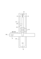
- a first storage space 310, a second storage space 320, and a soil section 400 located between the first storage space 310 and the second storage space 320 may be provided underground.
- the first storage space 310 and the second storage space 320 may be U-shaped trenches.
- at least the soil section 400 may simulate the soil environment in which the pipe 200 is actually buried.
- the soil environment may be composed of, for example, a surface layer such as asphalt, a roadbed such as crushed stone located below the surface layer, and a road body such as soil located below the roadbed.
- the pipe cutting test system 100 may be installed in the first storage space 310, the second storage space 320, and the soil section 400.
- the control device 40 and the depth adjustment device 60 may be installed in the first storage space 310.
- the imaging device 50 may be installed in the second storage space 320.
- the cutting device 10 may be installed in the soil section 400.
- the first sensor 20, the second sensor 30, and the pipe 200 may be installed across the first storage space 310, the soil section 400, and the second storage space 320.
- the cutting device 10 cuts the tube 200 housing the cable 210, with reference to FIG. 3.
- the cutting device 10 may be a pavement cutter.
- the cutting device 10 may have a disk-shaped blade that rotates about its axis.
- the cutting device 10 may be movable in the in-plane direction of the blade while rotating the blade.
- the cutting device 10 may be a hand-pushed type.
- the first sensor 20 is provided on the pipe 200.
- the first sensor 20 may be attached to the outer or inner surface of the pipe 200, or may be embedded in the pipe 200.
- the first sensor 20 may extend along the axial direction of the pipe 200.
- the first sensor 20 may be an optical core wire.
- the first sensor 20 may be connected to the control device 40 described below.
- a predetermined signal may flow to the first sensor 20.
- the first sensor 20 may break when the cutting device 10 contacts the pipe 200 at the first time.
- the second sensor 30 is provided on the cable 210.
- the second sensor 30 may be a core wire within the cable 210.
- the second sensor 30 may be an optical core wire.
- the second sensor 30 may be connected to the control device 40.
- a predetermined signal may flow to the second sensor 30.
- the second sensor 30 may break when the cutting device 10 contacts the cable 210 at the second time.
- the second sensor 30 may break when the cutting device 10 cuts the cable 210.
- the first sensor 20 and the second sensor 30 may be connected to the control device 40.
- the control device 40 may detect that the cutting device 10 has contacted the first sensor 20 at a first time by detecting that the signal from the first sensor 20 has been interrupted.
- the control device 40 may detect that the cutting device 10 has contacted the second sensor 30 at a second time by detecting that the signal from the second sensor 30 has been interrupted.
- the control device 40 receives a first signal from the first sensor 20 indicating the first time that the cutting device 10 has contacted the pipe 200, and receives a second signal from the second sensor 30 indicating the second time that the cutting device 10 has contacted the cable 210.
- the control device 40 may calculate the time difference dt between the first time and the second time.
- the control device 40 may display the first time, the second time, or the time difference dt on a screen or the like.
- the control device 40 may determine whether the pipe 200 has sufficient cut-resistance based on the time difference dt. For example, the control device 40 may determine that the pipe 200 has sufficient cut-resistance when the time difference dt is equal to or greater than a threshold value (e.g., 10 minutes).
- a threshold value e.g. 10 minutes
- the camera 50 may photograph the portion 200c of the tube 200 that is cut by the cutting device 10 and its vicinity. This configuration makes it possible to analyze the behavior of the tube 200, protective members, cable 210, etc. when the cutting device 10 is in contact with the tube 200.
- the camera 50 may photograph the cut surfaces of the tube 200 and cable 210 and their vicinity.
- the camera 50 may photograph sparks that are generated when the cutting device 10 cuts the tube 200.
- the camera 50 may capture video or still images.
- the imaging device 50 may determine that an abnormality has occurred and notify the worker.
- the imaging device 50 may be connected to the control device 40, and the control device 40 may determine that an abnormality has occurred and notify the worker.
- the imaging device 50 may be a night vision camera, an infrared camera, etc.
- the imaging device 50 may be fixed to a tripod.
- the height of the imaging device 50 may be adjustable.
- the height of the imaging device 50 may be remotely adjustable.
- the imaging device 50 may be installed near the tube 200.
- the depth adjustment device 60 may adjust the depth d of the pipe 200 from the surface of the soil portion 400 when at least the portion 200c of the pipe 200 to be cut by the cutting device 10 is embedded in the soil portion 400.
- the height of the surface of the soil portion 400 filled with the soil material may be equal to the height of the upper surface of the first storage space 310 and the upper surface of the second storage space 320.
- the depth adjustment device 60 may be provided in the soil portion 400 or in the vicinity of the soil portion 400. Referring to FIG. 1, two depth adjustment devices 60 may be provided side by side in the axial direction of the pipe 200. One or three or more depth adjustment devices 60 may be provided.
- the depth adjustment device 60 may include two bolts 61 and a pair of fasteners 62.
- the length of the bolt 61 may be designed based on the expected thickness of the soil in the soil portion 400, the depth d of the pipe 200 from the surface of the soil portion 400, etc.
- One end of the bolt 61 may be embedded or inserted into the first storage space 310 with the threaded portion 61t exposed.
- the spacing between the two bolts 61 may be designed to match the position of the through hole 62h of the fastener 62 described below.
- a first nut 63 may be inserted into the bolt 61.
- the height of the fastener 62 i.e., the depth d from the surface of the soil portion 400 of the pipe 200 clamped by the fastener 62, may be adjustable by the first nut 63.
- the fastener 62 may be composed of a curved portion 62c and a flat portion 62p connected to both ends of the curved portion 62c.
- the fastener 62 may be rectangular in plan view.
- the curved portion 62c may be semi-cylindrical.
- the shape of the curved portion 62c may match the shape of the tube 200.
- the tube 200 may be sandwiched between the two curved portions 62c.
- the flat portion 62p may extend along a line connecting both ends of the curved portion 62c.
- a through hole 62h may be formed on the flat portion 62p opposite the curved portion 62c.
- the cross-sectional shape of the through hole 62h may match the cross-sectional shape of the bolt 61.
- the bolt 61 may be inserted into the through hole 62h.
- the second nut 64 may be inserted into the bolt 61, and the pair of fasteners 62 may be fixed by the first nut 63 and the second nut 64.
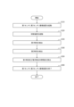
- FIGS 5 and 6 are flowcharts showing an example of a pipe cutting test method.
- the process shown in Figure 5 is so-called pre-processing that is performed before a pipe cutting test is performed.
- the process shown in Figure 6 shows the process of a pipe cutting test based on this pre-processing.
- the processes shown in Figures 5 and 6 may be performed by the pipe cutting test system 100.
- step S110 with reference to FIG. 3, the first sensor 20 and the second sensor 30 are attached.
- the first sensor 20 may be attached to the outer surface of the pipe 200.
- the second sensor 30 may be a core wire within the cable 210.
- the second sensor 30, which is a separate member from the cable 210, may be attached to the cable 210.
- the first sensor 20 and the second sensor 30 may be connected to the control device 40.
- step S120 the position of the pipe 200 is adjusted.
- the height of the fastener 62 i.e., the depth d of the pipe 200 from the surface of the soil portion 400 sandwiched between the fasteners 62, is adjusted by adjusting the height of the first nuts 63 inserted into the two bolts 61 embedded in the first storage space 310.
- the through holes 60h in one of the pair of fasteners 62 are inserted into the two bolts 61 with the curved portion 62c protruding from the flat portion 62p toward the bottom surface of the first storage space 310.
- the fastener 62 abuts against the first nut 63.
- the pipe 200 is then placed on the curved portion 62c.
- the axial position of the pipe 200 is adjusted by moving the pipe 200 along the axial direction relative to the curved portion 62c. Furthermore, the through hole 60h in the other of the pair of fasteners 62 is inserted onto the two bolts 61 with the curved portion 62c protruding from the flat portion 62p to the side opposite the bottom surface of the first storage space 310. The pipe 200 is sandwiched between the two curved portions 62c. Then, the second nut 64 is inserted onto the bolt 61, and the pair of fasteners 62 is fixed by the first nut 63 and the second nut 64.
- a protective member is attached.
- the outside of the pipe 200 may be covered with the protective member.
- the protective member may be inserted between the inside of the pipe 200 and the cable 210.
- the protective member may be provided only in the vicinity of the portion 200c to be cut by the cutting device 10. By providing the protective member only in the vicinity of the portion 200c to be cut by the cutting device 10, the cost, time, etc. of the pipe cutting test may be reduced. If the pipe 200 itself is made of a protective member, step S130 may be omitted.
- the soil section 400 is filled with soil material.
- the soil section 400 may first be filled with soil to form a road body.
- crushed stone may be filled into the soil section 400 to form a roadbed.
- the soil section 400 may be filled with asphalt, cement concrete, or the like to form a surface layer.
- the height of the surface of the formed surface layer may be equal to the height of the upper surface of the first storage space 310 and the upper surface of the second storage space 320.
- the soil material is not substantially filled into the first storage space 310 or the second storage space 320, and only the soil section 400 is filled with soil material, thereby efficiently realizing the environment required for the pipeline disconnection test.
- step S150 the position of the imaging device 50 is adjusted.
- the height of the imaging device 50 may be adjusted by opening and closing the tripod.
- the height of the imaging device 50 may be adjusted remotely.
- An operator, machine, etc. may adjust the position of the imaging device 50 from above the storage spaces 310, 320.
- step S210 with reference to FIG. 1, the first sensor 20 and the second sensor 30 are activated. Specifically, a predetermined signal may be sent from the first sensor 20 and the second sensor 30 to the control device 40. In step S210, the imaging device 50 may also be activated.
- step S220 the cutting device 10 is started. Specifically, the disk-shaped blade of the cutting device 10 may rotate. The cutting device 10 may move toward the pipe 200. The cutting device 10 may be moved by an operator.
- step S230 the first time when the cutting device 10 comes into contact with the pipe 200 is detected. Specifically, when the cutting device 10 comes into contact with the pipe 200 at the first time, the first sensor 20 is disconnected. Due to the disconnection, a specific signal that was flowing from the first sensor 20 to the control device 40 is interrupted. The control device 40 detects that the signal from the first sensor 20 has been interrupted. The control device 40 detects the first time from the content of the signal immediately before it was interrupted, the time of detection, etc.
- step S230 and step S240 the pipe 200 may be cut. If the protective function of the protective member is high, it will take a long time for the cutting device 10 to cut the pipe 200. Note that if the protective function of the protective member is very high, the cutting device 10 may not be able to cut the pipe 200. In this case, step S230, which will be described later, is omitted.
- step S240 the second time when the cutting device 10 comes into contact with the cable 210 is detected. Specifically, when the cutting device 10 comes into contact with the cable 210 at the second time, the second sensor 30 is disconnected. Due to the disconnection, a specific signal flowing from the second sensor 30 to the control device 40 is interrupted. The control device 40 detects that the signal from the second sensor 30 has been interrupted. The control device 40 detects the second time from the content of the signal immediately before it was interrupted, the time of detection, etc. At this point, the cutting device 10 may stop.
- step S250 the time difference dt between the first time and the second time is calculated.
- the control device 40 may display the first time, the second time, or the time difference dt on a screen or the like.
- the control device 40 may determine whether the pipe 200 has sufficient cut resistance based on the time difference dt. For example, the control device 40 may determine that the pipe 200 has sufficient cut resistance when the time difference dt is equal to or greater than a threshold value (e.g., 10 minutes). If step S230 is omitted, the control device 40 may determine that the pipe 200 has sufficient cut resistance.
- the control device 40 may display the determination result on a screen or the like. An operator may determine whether the pipe 200 has sufficient cut resistance based on the time difference dt.
- step S260 the first sensor 20 and the second sensor 30 are shut down.
- the imaging device 50 may also be shut down.
- the camera device 50 may capture an image of the portion of the pipe 200 that is to be cut by the cutting device 10. If the camera device 50 detects sudden damage to the protective member or large movement of the pipe 200 or cable 210, it may determine that an abnormality has occurred and notify the worker. The worker may stop the pipeline cutting test upon receiving the notification. The camera device 50 may determine the cause of the abnormality and notify the worker. The worker may determine the cause of the abnormality based on the notification from the camera device 50 or the video or still images. The worker may determine that an abnormality has occurred and may resolve the problem.
- the soil material of the soil portion 400 may be removed.
- the first nut 63 and the second nut 64 may then be loosened.
- the tube 200 may be removed from the depth adjustment device 60 in order to replace the tube with a new tube.
- a pipe disconnection test system comprising: (Additional Note 2) 2.
- a pipe cutting test method for performing a pipe cutting test in which a cutting device cuts a pipe that accommodates a cable comprising: detecting a first time when the cutting device contacts the tube; detecting a second time when the cutting device contacts the cable; calculating a time difference between the first time and the second time;
- a pipe disconnection test method comprising: (Additional Note 6) further comprising the step of photographing a portion of the tube being cut by the cutting device.
- the pipe cutting test method according to claim 5. (Additional Note 7) The pipe cut test method according to claim 5 or 6, further comprising a step of determining whether the pipe has sufficient cut resistance based on the time difference.
Landscapes
- Laying Of Electric Cables Or Lines Outside (AREA)
Priority Applications (2)
| Application Number | Priority Date | Filing Date | Title |
|---|---|---|---|
| JP2024565465A JP7787474B2 (ja) | 2022-12-20 | 2022-12-20 | 管路切断試験システム及び管路切断試験方法 |
| PCT/JP2022/046976 WO2024134792A1 (ja) | 2022-12-20 | 2022-12-20 | 管路切断試験システム及び管路切断試験方法 |
Applications Claiming Priority (1)
| Application Number | Priority Date | Filing Date | Title |
|---|---|---|---|
| PCT/JP2022/046976 WO2024134792A1 (ja) | 2022-12-20 | 2022-12-20 | 管路切断試験システム及び管路切断試験方法 |
Publications (1)
| Publication Number | Publication Date |
|---|---|
| WO2024134792A1 true WO2024134792A1 (ja) | 2024-06-27 |
Family
ID=91588079
Family Applications (1)
| Application Number | Title | Priority Date | Filing Date |
|---|---|---|---|
| PCT/JP2022/046976 Ceased WO2024134792A1 (ja) | 2022-12-20 | 2022-12-20 | 管路切断試験システム及び管路切断試験方法 |
Country Status (2)
| Country | Link |
|---|---|
| JP (1) | JP7787474B2 (https=) |
| WO (1) | WO2024134792A1 (https=) |
Citations (4)
| Publication number | Priority date | Publication date | Assignee | Title |
|---|---|---|---|---|
| WO2008065777A1 (en) * | 2006-11-29 | 2008-06-05 | Airec Engineering Corporation | Conduit inspection system and conduit inspection method |
| JP2009183052A (ja) * | 2008-01-30 | 2009-08-13 | Chugoku Electric Power Co Inc:The | 防護管装置 |
| WO2021245838A1 (ja) * | 2020-06-03 | 2021-12-09 | 日本電信電話株式会社 | 検知装置および検知方法 |
| WO2022244119A1 (ja) * | 2021-05-18 | 2022-11-24 | 日本電信電話株式会社 | 埋設管路撤去方法及び埋設管路撤去装置 |
-
2022
- 2022-12-20 JP JP2024565465A patent/JP7787474B2/ja active Active
- 2022-12-20 WO PCT/JP2022/046976 patent/WO2024134792A1/ja not_active Ceased
Patent Citations (4)
| Publication number | Priority date | Publication date | Assignee | Title |
|---|---|---|---|---|
| WO2008065777A1 (en) * | 2006-11-29 | 2008-06-05 | Airec Engineering Corporation | Conduit inspection system and conduit inspection method |
| JP2009183052A (ja) * | 2008-01-30 | 2009-08-13 | Chugoku Electric Power Co Inc:The | 防護管装置 |
| WO2021245838A1 (ja) * | 2020-06-03 | 2021-12-09 | 日本電信電話株式会社 | 検知装置および検知方法 |
| WO2022244119A1 (ja) * | 2021-05-18 | 2022-11-24 | 日本電信電話株式会社 | 埋設管路撤去方法及び埋設管路撤去装置 |
Also Published As
| Publication number | Publication date |
|---|---|
| JP7787474B2 (ja) | 2025-12-17 |
| JPWO2024134792A1 (https=) | 2024-06-27 |
Similar Documents
| Publication | Publication Date | Title |
|---|---|---|
| KR102008175B1 (ko) | 점검 및 진단용 드론을 이용한 댐 손상점검 방법 | |
| Makar | Diagnostic techniques for sewer systems | |
| CN111947605A (zh) | 一种边坡安全监测系统及其监测方法 | |
| KR101557865B1 (ko) | 하수관로의 cctv 데이터 및 상부지반의 gpr 데이터를 이용한 지반침하 진단 시스템 및 그 방법 | |
| KR101913747B1 (ko) | 지하 시설물 관리 방법 및 장치 | |
| KR101604050B1 (ko) | 도로터널 점검 장치 | |
| KR102210049B1 (ko) | 관로 내부 조사와 디펙트 판독을 통한 관로 애널라이징 시스템 | |
| JP7787474B2 (ja) | 管路切断試験システム及び管路切断試験方法 | |
| KR20210046169A (ko) | 휴대용 토사 천공장치 및 이를 이용한 매설설비 확인 보수방법과 안전접지 시공 방법 | |
| Aly et al. | Towards a fully automated monitoring system for Manhole Cover: Smart cities and IOT applications | |
| JP7678196B2 (ja) | 作業管理装置および作業管理方法 | |
| WO2019122717A1 (fr) | Procede pour deboucher une conduite destinee au transport de fluide d'hydrocarbure obturee par des hydrates | |
| JP7079055B2 (ja) | 凍害によるコンクリートの劣化を検知する光ファイバセンサの設置方法およびコンクリート構造物の劣化検知方法 | |
| KR20160053652A (ko) | 급경사지 현장조사 전자 야장 | |
| KR102856922B1 (ko) | 매설배관 굴착공사 사고감지를 위한 IoT 융합센서 디바이스 플랫폼 | |
| KR20220078301A (ko) | 지중 모니터링 장치 및 그 제어방법 | |
| Fabritius et al. | Distributed fibre optic temperature measurements for dam safety monitoring: current state of the art and further developments | |
| US10704380B2 (en) | System and method for detecting cross bores | |
| KR102954808B1 (ko) | 진동 및 온도 감지 센서를 이용하여 송유관의 이상현상을 탐지하는 방법 | |
| FR3142714A1 (fr) | Systeme de supervision d’un chantier ferroviaire | |
| Lee et al. | A vision-based system for inspection of expansion joints in concrete pavement | |
| FR3120929A1 (fr) | procédé de rénovation de canalisation par l’intérieur | |
| FR2852693A1 (fr) | Systemes embarques de detection predictive de defaillances des paliers d'appareils mobiles de travail du sol tels que des engins de travaux publics ou agricoles | |
| KR20200004544A (ko) | 이미지 처리를 이용한 고속도로 결빙 판별기기 | |
| RU2830960C1 (ru) | Способ обнаружения протечек воды в сети водоснабжения и отключения ее подачи |
Legal Events
| Date | Code | Title | Description |
|---|---|---|---|
| 121 | Ep: the epo has been informed by wipo that ep was designated in this application |
Ref document number: 22969180 Country of ref document: EP Kind code of ref document: A1 |
|
| WWE | Wipo information: entry into national phase |
Ref document number: 2024565465 Country of ref document: JP |
|
| NENP | Non-entry into the national phase |
Ref country code: DE |
|
| 122 | Ep: pct application non-entry in european phase |
Ref document number: 22969180 Country of ref document: EP Kind code of ref document: A1 |