WO2024134775A1 - 光コネクタおよび光コネクタユニット - Google Patents
光コネクタおよび光コネクタユニット Download PDFInfo
- Publication number
- WO2024134775A1 WO2024134775A1 PCT/JP2022/046915 JP2022046915W WO2024134775A1 WO 2024134775 A1 WO2024134775 A1 WO 2024134775A1 JP 2022046915 W JP2022046915 W JP 2022046915W WO 2024134775 A1 WO2024134775 A1 WO 2024134775A1
- Authority
- WO
- WIPO (PCT)
- Prior art keywords
- optical connector
- ferrule
- input side
- output side
- output
- Prior art date
- Legal status (The legal status is an assumption and is not a legal conclusion. Google has not performed a legal analysis and makes no representation as to the accuracy of the status listed.)
- Ceased
Links
Images








Classifications
-
- G—PHYSICS
- G02—OPTICS
- G02B—OPTICAL ELEMENTS, SYSTEMS OR APPARATUS
- G02B6/00—Light guides; Structural details of arrangements comprising light guides and other optical elements, e.g. couplings
- G02B6/24—Coupling light guides
- G02B6/36—Mechanical coupling means
- G02B6/38—Mechanical coupling means having fibre to fibre mating means
Definitions
- This disclosure relates to optical connectors and optical connector units.
- Multicore optical fibers are expected to be used as a transmission medium in future large-capacity transmission systems.
- a multicore optical fiber has multiple cores arranged in a single cladding with an outer diameter equal to or larger than that of a single-core optical fiber (e.g., 125 ⁇ m) or larger (e.g., 250 ⁇ m or less).
- a multicore optical fiber is provided with an additive (marker) that changes the refractive index near one of the cores in the cladding (see Non-Patent Document 1).
- the core near the marker is defined as the first core
- the cores are defined as the second core, third core, fourth core, etc. clockwise from the first core, making it possible to distinguish between the individual cores.
- optical connectors such as a single-core LC connector (see Non-Patent Document 2) and a multi-core MT connector (see Non-Patent Document 3) have been proposed.
- measures have been taken to suppress axial and rotational misalignment of the cores in order to reduce connection loss.
- the main components of an optical connector are an optical fiber, a ferrule, a housing, and an adapter, and the optical fiber is fixed to the ferrule with adhesive or the like, and the housing is fitted into the adapter.
- optical connectors When managing core numbers in a multi-core optical fiber (for example, making sure that the signal from the first core always passes through the first core), it is necessary to align the markers and connect the fibers together. For this reason, optical connectors must be connected in combination with an output optical connector that outputs light and an input optical connector that receives light. Since single-core optical fibers have only one core, there is no need to identify the cores, and existing single-core optical connectors and multi-core optical connectors do not distinguish between output optical connectors and input optical connectors.
- the objective of this disclosure is to provide an optical connector and optical connector unit that can connect corresponding cores in the output optical connector and the input optical connector without error when connecting multi-core optical fibers.
- the optical connector according to the present disclosure comprises a ferrule fixed to the end of one or more optical fibers, a housing that houses and fixes the ferrule, and an engaging portion provided on at least one of the ferrule and the housing and capable of engaging with an engaged portion provided on an adapter that houses the optical connector.
- the engaging portion is provided so that the portion of the optical connector that is housed in the adapter has a shape that is asymmetrical and one-fold symmetrical when viewed in the axial direction of the optical fiber.
- An optical connector unit includes a first optical connector, a second optical connector, and an adapter.
- the first optical connector comprises a first ferrule fixed to an end of a first optical fiber, a first housing to which the first ferrule is fixed, and a first engagement portion provided on at least one of the first ferrule and the first housing such that a portion of the first optical connector that is accommodated in the adapter has a shape that is asymmetrical and one-fold symmetrical when the first optical connector is viewed in the axial direction of the first optical fiber.
- the second optical connector comprises a second ferrule fixed to an end of a second optical fiber, a second housing to which the second ferrule is fixed, and a second engagement portion provided on at least one of the second ferrule and the second housing such that a portion of the second optical connector that is accommodated in the adapter has a shape that is asymmetrical and one-fold symmetrical different from that of the first optical connector when the second optical connector is viewed in the axial direction of the second optical fiber.
- the adapter comprises a first optical connector accommodating portion capable of accommodating the first optical connector, a first engaged portion provided in the first optical connector accommodating portion and capable of engaging with the first engaging portion when the first optical connector is accommodated in the first optical connector accommodating portion, a second optical connector accommodating portion capable of accommodating the second optical connector, and a second engaged portion provided in the second optical connector accommodating portion and capable of engaging with the second engaging portion when the second optical connector is accommodated in the second optical connector accommodating portion.
- optical connector and optical connector unit disclosed herein allow for the connection of corresponding cores in the output optical connector and input optical connector without error when connecting multi-core optical fibers.
- FIG. 1( a ) is a diagram illustrating one end of a 4-core multi-core optical fiber
- FIG. 1( b ) is a diagram illustrating one end of a 3-core multi-core optical fiber
- FIG. 1( c ) is a diagram illustrating one end of a 5-core multi-core optical fiber
- FIG. 1( d ) is a diagram illustrating one end of another 5-core multi-core optical fiber.
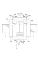
- FIG. 2 is a top view showing the optical connector unit according to the first embodiment.
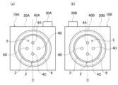
- FIG. 3A is a front view of the output side optical connector according to the first embodiment
- FIG. 3B is a front view of the input side optical connector according to the first embodiment.
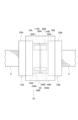
- FIG. 4 is a top view showing the optical connector unit according to the second embodiment.
- FIG. 5(a) is a front view of an output side optical connector according to the second embodiment
- FIG. 5(b) is a front view of an input side optical connector according to the second embodiment
- FIG. 6 is a top view showing the optical connector unit according to the third embodiment.
- FIG. 7A is a front view of an output side optical connector according to the third embodiment
- FIG. 7B is a front view of an input side optical connector according to the third embodiment.
- FIG. 8 is a top view showing the optical connector unit according to the fourth embodiment.
- FIG. 9A is a front view of an output side optical connector according to the fourth embodiment
- FIG. 9B is a front view of an input side optical connector according to the fourth embodiment.
- FIG. 10 is a top view showing the optical connector unit according to the fifth embodiment.
- FIG. 11A is a front view of an output side optical connector according to the fifth embodiment
- FIG. 11B is a front view of an input side optical connector according to the fifth embodiment
- FIG. 12 is a top view showing the optical connector unit according to the sixth embodiment.
- FIG. 13A is a front view of an output side optical connector according to the sixth embodiment
- FIG. 13B is a front view of an input side optical connector according to the sixth embodiment.
- FIG. 14 is a diagram showing an optical connector unit according to the seventh embodiment.
- Fig. 1(a) is a diagram illustrating one end of a four-core multi-core optical fiber 2 in which the first to fourth cores 4A to 4D are arranged in an annular shape.
- the multi-core optical fiber 2 includes a cladding 3, the first to fourth cores 4A to 4D arranged at equal intervals in an annular shape around the central axis of the cladding 3, and a marker 5 in which the refractive index is changed by an additive provided near the first core 4A.
- the outer periphery of the cladding 3 is preferably covered with a resin coating 6.
- FIG. 1(a) is a view from one end of the multi-core optical fiber 2, for example, an output end that outputs light, and the other end of the multi-core optical fiber 2, for example, an input end that inputs light, is a mirror image of Fig. 1(a).
- FIG. 1(b) is a diagram illustrating one end of a three-core multi-core optical fiber 2A in which the first to third cores 4A to 4C are arranged in an annular shape.
- FIG. 1(c) is a diagram illustrating one end of a five-core multi-core optical fiber 2B in which the first to fifth cores 4A to 4E are arranged in a cross shape.
- FIG. 1(d) is a diagram illustrating one end of a five-core multi-core optical fiber 2C in which the first to fifth cores 4A to 4E are arranged in an annular shape.
- the multi-core optical fiber is not limited to the multi-core optical fiber 2, and various core arrangement methods such as the multi-core optical fibers 2A to 2C and other methods are possible. Note that the configuration of the multi-core optical fibers 2A to 2C is the same as that of the multi-core optical fiber 2, so a detailed description thereof will be omitted.
- the multi-core optical fiber 2 shown in FIG. 1(a) is used for explanation, but it can be replaced with multi-core optical fibers 2A to 2C, etc., and still operate in the same way.
- the optical connector unit 1 is for single-core use and includes an output side optical connector 10A, an input side optical connector 10B and an adapter 50.
- the output side optical connector 10A includes an output side ferrule 40A, an output side housing 20A, and an output side engagement protrusion 30A as an engagement portion provided on the output side housing 20A.
- the output ferrule 40A is fixed to the optical output end of the multi-core optical fiber 2 with adhesive or the like.
- the output side ferrule 40A is fixed to the output side housing 20A.
- the output side housing 20A is provided with an output side engagement protrusion 30A protruding outward from the upper surface of the output side housing 20A.
- the output side engagement protrusion 30A is provided at a position shifted to one side (right in FIG. 3(a)) of the upper surface of the output side housing 20A with respect to a predetermined center line C passing through the center of the multi-core optical fiber 2.
- the output side housing 20A has an asymmetric shape with respect to the center line C.
- the output side engagement protrusion 30A is provided so that the part of the output side optical connector 10A that is accommodated in the adapter 50 has an asymmetric shape and a one-time rotationally symmetric shape when viewed in the axial direction of the multi-core optical fiber 2.
- a one-fold rotationally symmetric shape is a shape that overlaps with itself only when rotated 360 degrees around the axial direction of the multi-core optical fiber 2.
- the input side optical connector 10B includes an input side ferrule 40B, an input side housing 20B, and an input side engagement protrusion 30B as an engagement portion provided on the input side housing 20B.
- the input ferrule 40B is fixed to the optical input end of the multi-core optical fiber 2 with adhesive or the like.
- the input ferrule 40B has the same shape as the output ferrule 40A.
- the input side ferrule 40B is fixed to the input side housing 20B.
- the input side housing 20B is provided with an input side engagement protrusion 30B protruding outward from the upper surface of the input side housing 20B.
- the input side engagement protrusion 30B is provided at a position shifted to the other side (left in FIG. 3(b)) of the upper surface of the input side housing 20B with respect to a predetermined center line C passing through the center of the multi-core optical fiber 2.
- the input side housing 20B has an asymmetric shape with respect to the center line C.
- the input side engagement protrusion 30B is provided so that the part of the input side optical connector 10B that is accommodated in the adapter 50 has an asymmetric shape different from that of the input side optical connector 10A and a rotationally symmetric shape with one-time symmetry when viewed in the axial direction of the multi-core optical fiber 2.
- the input side housing 20B and the input side engagement protrusion 30B have a mirror image shape with respect to the output side housing 20A and the output side engagement protrusion 30A.
- the marker 5 on the optical input side end face of the multi-core optical fiber 2 on the input side optical connector 10B side is arranged so as to be a mirror image of the marker 5 on the optical output side end face of the multi-core optical fiber 2 on the output side optical connector 10A side.
- the adapter 50 has an output side optical connector housing portion that houses the output side optical connector 10A therein, and an input side optical connector housing portion that houses the input side optical connector 10B therein.
- the output side optical connector accommodating portion includes an output side housing accommodating portion 70A that accommodates the output side housing 20A therein, and an output side ferrule accommodating portion 80A that accommodates the output side ferrule 40A therein.
- the output side housing accommodating portion 70A is provided with an output side engagement groove 60A as an engaged portion that engages with the output side engagement protrusion 30A and guides the insertion of the output side optical connector 10A when the output side optical connector 10A is inserted into the output side optical connector accommodating portion.
- the input side optical connector accommodating portion includes an input side housing accommodating portion 70B that accommodates the input side housing 20B therein, and an input side ferrule accommodating portion 80B that accommodates the input side ferrule 40B therein.
- the input side housing accommodating portion 70B is provided with an input side engagement groove 60B as an engaged portion that engages with the input side engagement protrusion 30B and guides the insertion of the input side optical connector 10B when the input side optical connector 10B is inserted into the input side optical connector accommodating portion.
- the input side optical connector accommodating portion is configured to be a mirror image of the output side optical connector accommodating portion.
- the output side engagement protrusion 30A engages with the output side engagement groove 60A, guiding the insertion of the output side optical connector 10A. Then, the end face of the output side ferrule 40A abuts against the end face of the output side ferrule housing 80A, and the output side optical connector 10A is housed in the correct position of the adapter 50.
- the input side engagement protrusion 30B engages with the input side engagement groove 60B, guiding the insertion of the input side optical connector 10B. Then, the end face of the input side ferrule 40B abuts against the end face of the input side ferrule housing 80B, and the input side optical connector 10B is housed in the correct position in the adapter 50.
- the multi-core optical fiber 2 on the output side optical connector 10A side and the multi-core optical fiber 2 on the input side optical connector 10B side come into surface contact.
- the marker 5 of the multi-core optical fiber 2 on the output side optical connector 10A side and the marker 5 of the multi-core optical fiber 2 on the input side optical connector 10B side are in the same position and come into surface contact with each other.
- the first to fourth cores 4A to 4D of the multi-core optical fiber 2 on the output side optical connector 10A side and the first to fourth cores 4A to 4D of the multi-core optical fiber 2 on the input side optical connector 10B side come into surface contact with each other, respectively.
- the optical signals output from the first to fourth cores 4A to 4D of the multi-core optical fiber 2 on the output side optical connector 10A side are communicably connected so as to be input to the first to fourth cores 4A to 4D of the multi-core optical fiber 2 on the input side optical connector 10B side, respectively.
- the first core 4A of the multi-core optical fiber 2 on the output side optical connector 10A side and the fourth core 4D of the multi-core optical fiber 2 on the input side optical connector 10B side may be in surface contact with each other to be connected so that optical signals can be communicated.
- the remaining three cores 4B to 4D of the multi-core optical fiber 2 on the output side optical connector 10A side and the remaining three cores 4A to 4C of the multi-core optical fiber 2 on the input side optical connector 10B side are in surface contact with each other, respectively, to be connected so that optical signals can be communicated.
- the connection relationship between the first to fourth cores 4A to 4D of the multi-core optical fiber 2 on the output side optical connector 10A side and the first to fourth cores 4A to 4D of the multi-core optical fiber 2 on the input side optical connector 10B side may be set arbitrarily depending on the purpose of use.
- the output side optical connector 10A is to be erroneously inserted into the input side optical connector housing portion of the adapter 50.
- the output side engagement protrusion 30A of the output side optical connector 10A and the input side engagement groove 60B of the adapter 50 are in different positions, so the output side engagement protrusion 30A cannot engage with the input side engagement groove 60B. This prevents the output side optical connector 10A from being erroneously inserted into the input side optical connector housing portion of the adapter 50.
- the input side optical connector 10B is erroneously inserted into the output side optical connector housing portion of the adapter 50.
- the input side engagement protrusion 30B of the input side optical connector 10B and the output side engagement groove 60A of the adapter 50 are in different positions, so the input side engagement protrusion 30B cannot engage with the output side engagement groove 60A. This prevents the input side optical connector 10B from being erroneously inserted into the output side optical connector housing portion of the adapter 50.
- output side engagement protrusion 30A on the output side optical connector 10A side and the input side engagement protrusion 30B on the input side optical connector 10B side are arranged to be mirror images, this is not limited to this. Any positional relationship and shape may be used as long as the output side engagement protrusion 30A and the input side engagement protrusion 30B can prevent the output side optical connector 10A from being erroneously inserted into the input side optical connector accommodating portion, and the input side optical connector 10B from being erroneously inserted into the output side optical connector accommodating portion.
- the output side engagement groove 60A may be provided in a position and shape that engages with the output side engagement protrusion 30A
- the input side engagement groove 60B may be provided in a position and shape that engages with the input side engagement protrusion 30B.
- housings 20A, 20B are provided with the engaging protrusions 30A, 30B and the adapter 50 is provided with the engaging grooves 60A, 60B, this is not limited to the above.
- the housings 20A, 20B may be provided with engaging grooves and the adapter 50 may be provided with engaging protrusions.
- both the housings 20A, 20B and the adapter 50 may be provided with engaging protrusions and engaging grooves that engage with each other.
- the optical connector unit 1A is for a single core and includes an output side optical connector 11A, an input side optical connector 11B and an adapter 51.
- the output side optical connector 11A includes an output side ferrule 41A, an output side housing 21A, and an output side engagement protrusion 31A as an engagement portion provided on the output side ferrule 41A.
- the output ferrule 41A is fixed to the optical output end of the multi-core optical fiber 2 with adhesive or the like.
- the output ferrule 41A is provided with an output engagement protrusion 31A protruding from the top of the output ferrule 41A to the outside.
- the output engagement protrusion 31A is provided at a position shifted to one side of the top of the output ferrule 41A (right in FIG. 5(a)) with respect to a predetermined center line C passing through the center of the multi-core optical fiber 2.
- the output ferrule 41A has an asymmetric shape with respect to the center line C.
- the output engagement protrusion 31A is provided so that the part of the output optical connector 11A that is accommodated in the adapter 51 has an asymmetric shape and a one-time rotationally symmetric shape when viewed in the axial direction of the multi-core optical fiber 2.
- the output side ferrule 41A is fixed to the output side housing 21A.
- the input side optical connector 11B includes an input side ferrule 41B, an input side housing 21B, and an input side engagement protrusion 31B that serves as an engagement portion provided on the input side ferrule 41B.
- the input ferrule 41B is fixed to the optical input end of the multi-core optical fiber 2 with adhesive or the like.
- the input ferrule 41B is provided with an input engagement protrusion 31B protruding from the top of the input ferrule 41B to the outside.
- the input engagement protrusion 31B is provided at a position shifted to the other side of the top of the input ferrule 41B (left in FIG. 5(b)) with respect to a predetermined center line C passing through the center of the multi-core optical fiber 2.
- the input ferrule 41B has an asymmetric shape with respect to the center line C.
- the input engagement protrusion 31B is provided so that the part of the input optical connector 11B that is accommodated in the adapter 51 has an asymmetric shape different from that of the input optical connector 11A and a rotationally symmetric shape with one-time symmetry when viewed in the axial direction of the multi-core optical fiber 2.
- the input side ferrule 41B is fixed to the input side housing 21B.
- the input side housing 21B has the same shape as the output side housing 21A.
- the input ferrule 41B and the input engagement protrusion 31B are shaped as mirror images of the output ferrule 41A and the output engagement protrusion 31A.
- the marker 5 on the optical input end face of the multi-core optical fiber 2 on the input optical connector 11B side is arranged so as to be mirror symmetrical to the marker 5 on the optical output end face of the multi-core optical fiber 2 on the output optical connector 11A side.
- the adapter 51 has an output side optical connector housing portion that houses the output side optical connector 11A therein, and an input side optical connector housing portion that houses the input side optical connector 11B therein.
- the output-side optical connector accommodating portion includes an output-side housing accommodating portion 71A that accommodates the output-side housing 21A therein, and an output-side ferrule accommodating portion 81A that accommodates the output-side ferrule 41A therein.
- the output-side optical connector accommodating portion may be configured to include only the output-side ferrule accommodating portion 81A without including the output-side housing accommodating portion 71A.
- An output side engagement groove 61A is provided on the inner surface of the output side ferrule accommodating portion 81A as an engaged portion that engages with the output side engagement protrusion 31A and guides the insertion of the output side optical connector 11A when the output side optical connector 11A is inserted into the output side optical connector accommodating portion.
- the input side optical connector accommodating portion includes an input side housing accommodating portion 71B that accommodates the input side housing 21B therein, and an input side ferrule accommodating portion 81B that accommodates the input side ferrule 41B therein.
- the input side optical connector accommodating portion may be configured to have only the input side ferrule accommodating portion 81B without providing the input side housing accommodating portion 71B.
- the inner surface of the input side ferrule accommodating portion 81B is provided with an input side engagement groove 61B as an engaged portion that engages with the input side engagement protrusion 31B and guides the insertion of the input side optical connector 11B when the input side optical connector 11B is inserted into the input side optical connector accommodating portion.
- the input side optical connector accommodating portion is configured to be a mirror image of the output side optical connector accommodating portion, as shown in FIG. 4.
- the output side optical connector 11A When the output side optical connector 11A is inserted into the output side optical connector housing, the output side engagement protrusion 31A engages with the output side engagement groove 61A, guiding the insertion of the output side optical connector 11A. Then, the end face of the output side ferrule 41A abuts against the end face of the output side ferrule housing 81A, and the output side optical connector 11A is housed in the correct position in the adapter 51.
- the input side engagement protrusion 31B engages with the input side engagement groove 61B, guiding the insertion of the input side optical connector 11B. Then, the end face of the input side ferrule 41B abuts against the end face of the input side ferrule housing 81B, and the input side optical connector 11B is housed in the correct position of the adapter 51.
- the optical signals output from the first to fourth cores 4A to 4D of the multi-core optical fiber 2 on the output side optical connector 11A side are communicatively connected so as to be input to the first to fourth cores 4A to 4D of the multi-core optical fiber 2 on the input side optical connector 11B side, respectively.
- the output side optical connector 11A is to be erroneously inserted into the input side optical connector housing portion of the adapter 51.
- the output side engagement protrusion 31A of the output side optical connector 11A and the input side engagement groove 61B of the adapter 51 are in different positions, so the output side engagement protrusion 31A cannot engage with the input side engagement groove 61B. This prevents the output side optical connector 11A from being erroneously inserted into the input side optical connector housing portion of the adapter 51.
- the input side optical connector 11B is erroneously inserted into the output side optical connector housing portion of the adapter 51.
- the input side engagement protrusion 31B of the input side optical connector 11B and the output side engagement groove 61A of the adapter 51 are in different positions, so the input side engagement protrusion 31B cannot engage with the output side engagement groove 61A. This prevents the input side optical connector 11B from being erroneously inserted into the output side optical connector housing portion of the adapter 51.
- the output side ferrule 41A and the input side ferrule 41B are installed in the multi-core optical fiber 2 at a factory, and then assembled into the output side optical connector 11A and the input side optical connector 11B on-site. If the output side ferrule 41A and the input side ferrule 41B, which have different shapes, are already installed in the multi-core optical fiber 2 at a factory, it is possible to prevent mistakes in assembling the output side optical connector 11A and the input side optical connector 11B on-site.
- output side engagement protrusion 31A on the output side optical connector 11A side and the input side engagement protrusion 31B on the input side optical connector 11B side are arranged to be mirror images, this is not limited to this. Any positional relationship and shape may be used as long as the output side engagement protrusion 31A and the input side engagement protrusion 31B can prevent the output side optical connector 11A from being erroneously inserted into the input side optical connector accommodating portion and the input side optical connector 11B from being erroneously inserted into the output side optical connector accommodating portion.
- the output side engagement groove 61A may be provided in a position and shape that engages with the output side engagement protrusion 31A
- the input side engagement groove 61B may be provided in a position and shape that engages with the input side engagement protrusion 31B.
- the configurations of the first and second embodiments can be combined in any way.
- the second embodiment can be combined with a configuration in which, like the first embodiment, the housings 21A and 21B are provided with engagement protrusions or engagement grooves, or both, and the housing accommodating portions 71A and 71B are provided with engagement grooves or engagement protrusions, or both.
- the optical connector unit 1B is for multi-core use and includes an output side optical connector 12A, an input side optical connector 12B and an adapter 52.
- the output side optical connector 12A includes an output side ferrule 42A, an output side housing 22A, and an output side engagement protrusion 32A as an engagement portion provided on the output side housing 22A.
- the optical output end portions of the parallel multiple (12 in FIG. 7(a)) multi-core optical fibers 2 are fixed to the parallel multiple (12 in FIG. 7(a)) ports provided corresponding to each other with an adhesive or the like.
- the number of ports provided in the output ferrule 42A may be determined arbitrarily according to the number of multi-core optical fibers 2 to be connected.
- a first guide hole 102A and a second guide hole 112A are provided on the tip surface of the output ferrule 42A.
- the first guide hole 102A and the second guide hole 112A are provided with the same size so that the multiple ports are lined up in a straight line between them.
- the output side ferrule 42A is fixed to the output side housing 22A.
- the output side housing 22A is provided with an output side engagement protrusion 32A protruding outward from the upper surface of the output side housing 22A.
- the output side engagement protrusion 32A is provided at a position shifted to one side (right in FIG. 7(a)) of the upper surface of the output side housing 22A with respect to a predetermined center line C passing through the center of the parallel multiple multi-core optical fibers 2.
- the output side housing 22A has an asymmetric shape with respect to the center line C.
- the output side engagement protrusion 32A is provided so that the part of the output side optical connector 12A that is accommodated in the adapter 52 has an asymmetric shape and a one-time rotationally symmetric shape when viewed in the axial direction of the multi-core optical fiber 2.
- the input side optical connector 12B includes an input side ferrule 42B, an input side housing 22B, and an input side engagement protrusion 32B as an engagement portion provided on the input side housing 22B.
- the optical input side ends of the multiple (12 in FIG. 7(b)) parallel multi-core optical fibers 2 are fixed with adhesive or the like to multiple (12 in FIG. 7(b)) parallel ports provided corresponding to each other.
- the ports provided in the input ferrule 42B are provided at positions that are mirror images of the same number of ports in the output ferrule 42A.
- the multiple multi-core optical fibers 2 fixed to the ports of the input ferrule 42B are fixed to positions that are mirror images of the multi-core optical fibers 2 to be connected to the multiple multi-core optical fibers 2 fixed to the ports of the output ferrule 42A.
- the tip surface of the input side ferrule 42B is provided with a first guide hole 102B and a second guide hole 112B. Similar to the output side ferrule 42A, the first guide hole 102B and the second guide hole 112B of the input side ferrule 42B are provided with the same size so that multiple ports are aligned in a straight line between them. In the third embodiment, the input side ferrule 42B has the same shape as the output side ferrule 42A.
- the input side ferrule 42B is fixed to the input side housing 22B.
- the input side housing 22B is provided with an input side engagement protrusion 32B protruding outward from the upper surface of the input side housing 22B.
- the input side engagement protrusion 32B is provided at a position shifted to the other side (left in FIG. 7(b)) of the upper surface of the input side housing 22B with respect to a predetermined center line C passing through the center of the parallel multiple multi-core optical fibers 2.
- the input side housing 22B has an asymmetric shape with respect to the center line C.
- the input side engagement protrusion 32B is provided so that the part of the input side optical connector 12B that is accommodated in the adapter 52 has an asymmetric shape different from that of the input side optical connector 12A and a rotationally symmetric shape with one-time symmetry when viewed in the axial direction of the multi-core optical fiber 2.
- the input side housing 22B and the input side engagement protrusion 32B are shaped as mirror images of the output side housing 22A and the output side engagement protrusion 32A.
- the markers 5 on the optical input side end faces of the multiple multi-core optical fibers 2 on the input side optical connector 12B side are arranged so as to be mirror images of the markers 5 on the optical output side end faces of the multiple multi-core optical fibers 2 on the output side optical connector 12A side.
- the adapter 52 has an output side optical connector housing portion that houses the output side optical connector 12A therein, and an input side optical connector housing portion that houses the input side optical connector 12B therein.
- the output side optical connector accommodating portion includes an output side housing accommodating portion 72A that accommodates the output side housing 22A therein, and an output side ferrule accommodating portion 82A that accommodates the output side ferrule 42A therein.
- the output side housing accommodating portion 72A is provided with an output side engagement groove 62A as an engaged portion that engages with the output side engagement protrusion 32A and guides the insertion of the output side optical connector 12A when the output side optical connector 12A is inserted into the output side optical connector accommodating portion.
- the output side ferrule accommodating portion 82A is also provided with a first guide pin 92B that engages with the first guide hole 102A, and a second guide pin 92A that engages with the second guide hole 112A.
- the input side optical connector accommodation section includes an input side housing accommodation section 72B that accommodates the input side housing 22B therein, and an input side ferrule accommodation section 82B that accommodates the input side ferrule 42B therein.
- the input side housing accommodation section 72B is provided with an input side engagement groove 62B as an engaged section that engages with the input side engagement protrusion 32B and guides the insertion of the input side optical connector 12B when the input side optical connector 12B is inserted into the input side optical connector accommodation section.
- the input side ferrule accommodation section 82B is provided with a first guide pin 92B that engages with the first guide hole 102B and a second guide pin 92A that engages with the second guide hole 112B. As shown in FIG. 6, the input side optical connector accommodation section is configured to be a mirror image of the output side optical connector accommodation section.
- the output side optical connector 12A When the output side optical connector 12A is inserted into the output side optical connector housing, the output side engagement groove 62A and the output side engagement protrusion 32A, the first guide hole 102A and the first guide pin 92B, and the second guide hole 112A and the second guide pin 92A each engage to guide the insertion. Then, the end face of the output side ferrule 42A abuts against the end face of the output side ferrule housing 82A, and the output side optical connector 12A is housed in the correct position of the adapter 52.
- the input side optical connector 12B When the input side optical connector 12B is inserted into the input side optical connector housing, the input side engagement groove 62B engages with the input side engagement protrusion 32B, the first guide hole 102B engages with the first guide pin 92B, and the second guide hole 112B engages with the second guide pin 92A, respectively, to guide the insertion. Then, the end face of the input side ferrule 42B abuts against the end face of the input side ferrule housing 82B, and the input side optical connector 12B is housed in the correct position in the adapter 52.
- the multiple multi-core optical fibers 2 on the output side optical connector 12A side and the multiple multi-core optical fibers 2 on the input side optical connector 12B side are in surface contact with each other.
- the markers 5 of the multiple multi-core optical fibers 2 on the output side optical connector 12A side and the markers 5 of the multiple multi-core optical fibers 2 on the input side optical connector 12B side are in the same position and are in surface contact with each other.
- the first to fourth cores 4A to 4D of the multiple multi-core optical fibers 2 on the output side optical connector 12A side and the first to fourth cores 4A to 4D of the multiple multi-core optical fibers 2 on the input side optical connector 12B side are in surface contact with each other. Then, they are communicatively connected so that the optical signals output from the first to fourth cores 4A to 4D of the multiple multi-core optical fibers 2 on the output side optical connector 12A side are input to the first to fourth cores 4A to 4D of the multiple multi-core optical fibers 2 on the input side optical connector 10B side.
- markers 5 of the multiple multi-core optical fibers 2 on the output side optical connector 12A side and the markers 5 of the multiple multi-core optical fibers 2 on the input side optical connector 12B side are in the same position, this is not limited to this, as in the first embodiment.
- the output side optical connector 12A is erroneously inserted into the input side optical connector housing portion of the adapter 52.
- the output side engagement protrusion 32A of the output side optical connector 12A and the input side engagement groove 62B of the adapter 52 are in different positions, so the output side engagement protrusion 32A cannot engage with the input side engagement groove 62B. This prevents the output side optical connector 12A from being erroneously inserted into the input side optical connector housing portion of the adapter 52.
- the input side optical connector 12B is erroneously inserted into the output side optical connector housing portion of the adapter 52.
- the input side engagement protrusion 32B of the input side optical connector 12B and the output side engagement groove 62A of the adapter 52 are in different positions, so the input side engagement protrusion 32B cannot engage with the output side engagement groove 62A. This prevents the input side optical connector 12B from being erroneously inserted into the output side optical connector housing portion of the adapter 52.
- guide holes and guide pins are provided in both the pair of output ferrule 42A and output ferrule accommodating portion 82A and the pair of input ferrule 42B and input ferrule accommodating portion 82B, but this is not limited to the above. Guide holes and guide pins may be provided in either the pair of output ferrule 42A and output ferrule accommodating portion 82A or the pair of input ferrule 42B and input ferrule accommodating portion 82B. Even with this configuration, it is possible to prevent erroneous insertion of the output optical connector 12A and the input optical connector 12B into the adapter 52.
- output side engagement protrusion 32A on the output side optical connector 12A side and the input side engagement protrusion 32B on the input side optical connector 12B side are arranged to be mirror images, this is not limited to this. Any positional relationship and shape may be used as long as the output side engagement protrusion 32A and the input side engagement protrusion 32B can prevent the output side optical connector 12A from being erroneously inserted into the input side optical connector housing portion and the input side optical connector 12B from being erroneously inserted into the output side optical connector housing portion.
- the output side engagement groove 62A may be provided in a position and shape that engages with the output side engagement protrusion 32A
- the input side engagement groove 62B may be provided in a position and shape that engages with the input side engagement protrusion 32B.
- housings 22A and 22B are provided with the engagement protrusions 32A and 32B, and the adapter 52 is provided with the engagement grooves 62A and 62B, this is not limited to the above.
- the housings 22A and 22B may be provided with engagement grooves, and the adapter 52 may be provided with engagement protrusions.
- both the housings 22A and 22B and the adapter 52 may be provided with engagement protrusions and engagement grooves that engage with each other.
- optical connector unit 1C according to a fourth embodiment will be described with reference to Figures 8, 9(a) and 9(b).
- the optical connector unit 1C is for multi-core use and includes an output side optical connector 13A, an input side optical connector 13B and an adapter 53.
- the output side optical connector 13A includes an output side ferrule 43A, an output side housing 23A, and an output side engagement protrusion 33A as an engagement portion provided on the output side ferrule 43A.
- the optical output end portions of the parallel multiple (12 in FIG. 9(a)) multi-core optical fibers 2 are fixed to the parallel multiple (12 in FIG. 9(a)) ports that correspond to each other with an adhesive or the like.
- the number of ports provided in the output ferrule 43A may be determined arbitrarily depending on the number of multi-core optical fibers 2 to be connected.
- the output side ferrule 43A is provided with an output side engagement protrusion 33A protruding outward from the upper surface of the output side ferrule 43A.
- the output side engagement protrusion 33A is provided at a position shifted to one side (right in FIG. 9(a)) of the upper surface of the output side ferrule 43A with respect to a predetermined center line C passing through the center of the parallel multiple multi-core optical fibers 2.
- the output side ferrule 43A has an asymmetric shape with respect to the center line C.
- the output side engagement protrusion 33A is provided so that the part of the output side optical connector 13A that is accommodated in the adapter 53 has an asymmetric shape and a one-time rotationally symmetric shape when viewed in the axial direction of the multi-core optical fiber 2.
- the tip surface of the output ferrule 43A is provided with a first guide hole 103A and a second guide hole 113A.
- the first guide hole 103A and the second guide hole 113A are provided with the same size so that multiple ports are aligned in a straight line between them.
- the output side ferrule 43A is fixed to the output side housing 23A.
- the input side optical connector 13B includes an input side ferrule 43B, an input side housing 23B, and an input side engagement protrusion 33B that serves as an engagement portion provided on the input side ferrule 43B.
- the optical input side ends of the multiple (12 in FIG. 9(b)) parallel multi-core optical fibers 2 are fixed with adhesive or the like to multiple (12 in FIG. 9(b)) parallel ports provided corresponding to each other.
- the ports provided in the input ferrule 43B are provided at positions that are mirror images of the same number of ports in the output ferrule 43A.
- the multiple multi-core optical fibers 2 fixed to the ports of the input ferrule 43B are fixed to positions that are mirror images of the multi-core optical fibers 2 to be connected to the multiple multi-core optical fibers 2 fixed to the ports of the output ferrule 43A.
- the input side ferrule 43B is provided with an input side engagement protrusion 33B protruding outward from the upper surface of the input side ferrule 43B.
- the input side engagement protrusion 33B is provided at a position shifted to the other side (left in FIG. 9(b)) of the upper surface of the input side ferrule 43B with respect to a predetermined center line C passing through the center of the parallel multiple multi-core optical fibers 2.
- the input side ferrule 43B has an asymmetric shape with respect to the center line C.
- the input side engagement protrusion 33B is provided so that the part of the input side optical connector 13B that is accommodated in the adapter 53 has an asymmetric shape different from that of the input side optical connector 13A and a rotationally symmetric shape with one-time symmetry when viewed in the axial direction of the multi-core optical fiber 2.
- the tip surface of the input ferrule 43B is provided with a first guide hole 103B and a second guide hole 113B. Similar to the output ferrule 43A, the first guide hole 103B and the second guide hole 113B of the input ferrule 43B are provided with the same size so that multiple ports are lined up in a straight line between them.
- the input side ferrule 43B is fixed to the input side housing 23B.
- the input side housing 23B has the same shape as the output side housing 23A.
- the input ferrule 43B and the input engagement protrusion 33B are shaped as mirror images of the output ferrule 43A and the output engagement protrusion 33A.
- the markers 5 on the optical input end faces of the multiple multi-core optical fibers 2 on the input optical connector 13B side are arranged so as to be mirror images of the markers 5 on the optical output end faces of the multiple multi-core optical fibers 2 on the output optical connector 13A side.
- the adapter 53 has an output side optical connector housing portion that houses the output side optical connector 13A therein, and an input side optical connector housing portion that houses the input side optical connector 13B therein.
- the output side optical connector accommodating section includes an output side housing accommodating section 73A that accommodates the output side housing 23A therein, and an output side ferrule accommodating section 83A that accommodates the output side ferrule 43A therein.
- the output side optical connector accommodating section may be configured to have only the output side ferrule accommodating section 83A without providing the output side housing accommodating section 73A.
- the inner surface of the output side ferrule accommodating section 83A is provided with an output side engagement groove 63A as an engaged section that engages with the output side engagement protrusion 33A and guides the insertion of the output side optical connector 13A when the output side optical connector 13A is inserted into the output side optical connector accommodating section.
- the output side ferrule accommodating section 83A is also provided with a first guide pin 93B that engages with the first guide hole 103A and a second guide pin 93A that engages with the second guide hole 113A.
- the input side optical connector accommodating section includes an input side housing accommodating section 73B that accommodates the input side housing 23B therein, and an input side ferrule accommodating section 83B that accommodates the input side ferrule 43B therein.
- the input side optical connector accommodating section may be configured to have only the input side ferrule accommodating section 83B without providing the input side housing accommodating section 73B.
- the input side ferrule accommodating section 83B has an input side engagement groove 63B on the inner surface thereof as an engaged section that engages with the input side engagement protrusion 33B and guides the insertion of the input side optical connector 13B when the input side optical connector 13B is inserted into the input side optical connector accommodating section.
- the input side ferrule accommodating section 83B also has a first guide pin 93B that engages with the first guide hole 103B and a second guide pin 93A that engages with the second guide hole 113B.
- the input side optical connector accommodating section is configured to be mirror symmetrical to the output side optical connector accommodating section, as shown in FIG. 8.
- the output side optical connector 13A When the output side optical connector 13A is inserted into the output side optical connector housing, the output side engagement groove 63A and the output side engagement protrusion 33A, the first guide hole 103A and the first guide pin 93B, and the second guide hole 113A and the second guide pin 93A each engage to guide the insertion. Then, the end face of the output side ferrule 43A abuts against the end face of the output side ferrule housing 83A, and the output side optical connector 13A is housed in the correct position in the adapter 53.
- the input side optical connector 13B When the input side optical connector 13B is inserted into the input side optical connector housing, the input side engagement groove 63B and the input side engagement protrusion 33B, the first guide hole 103B and the first guide pin 93B, and the second guide hole 113B and the second guide pin 93A engage with each other to guide the insertion. Then, the end face of the input side ferrule 43B abuts against the end face of the input side ferrule housing 83B, and the input side optical connector 13B is housed in the correct position of the adapter 53.
- the output side optical connector 13A is to be erroneously inserted into the input side optical connector housing portion of the adapter 53.
- the output side engagement protrusion 33A of the output side optical connector 13A and the input side engagement groove 63B of the adapter 53 are in different positions, so the output side engagement protrusion 33A cannot engage with the input side engagement groove 63B. This prevents the output side optical connector 13A from being erroneously inserted into the input side optical connector housing portion of the adapter 53.
- the input side optical connector 13B is erroneously inserted into the output side optical connector housing portion of the adapter 53.
- the input side engagement protrusion 33B of the input side optical connector 13B and the output side engagement groove 63A of the adapter 53 are in different positions, so the input side engagement protrusion 33B cannot engage with the output side engagement groove 63A. This prevents the input side optical connector 13B from being erroneously inserted into the output side optical connector housing portion of the adapter 53.
- guide holes and guide pins are provided in both the pair of output ferrule 43A and output ferrule accommodating portion 83A and the pair of input ferrule 43B and input ferrule accommodating portion 83B, this is not limiting. Guide holes and guide pins may be provided in either the pair of output ferrule 43A and output ferrule accommodating portion 83A or the pair of input ferrule 43B and input ferrule accommodating portion 83B. With this configuration, it is possible to prevent erroneous insertion of output optical connector 13A and input optical connector 13B into adapter 53.
- output side engagement protrusion 33A on the output side optical connector 13A side and the input side engagement protrusion 33B on the input side optical connector 13B side are arranged to be mirror images, this is not limited to this. Any positional relationship and shape may be used as long as the output side engagement protrusion 33A and the input side engagement protrusion 33B can prevent the output side optical connector 13A from being erroneously inserted into the input side optical connector accommodating portion and the input side optical connector 13B from being erroneously inserted into the output side optical connector accommodating portion.
- the output side engagement groove 63A may be provided in a position and shape that engages with the output side engagement protrusion 33A
- the input side engagement groove 63B may be provided in a position and shape that engages with the input side engagement protrusion 33B.
- the fourth embodiment may be combined with a configuration in which, for example, the housings 23A and 23B are provided with engagement protrusions or engagement grooves, or both, as in the third embodiment, and the housing accommodating portions 73A and 73B are provided with engagement grooves or engagement protrusions, or both.
- the optical connector unit 1D includes an output side optical connector 14A, an input side optical connector 14B and an adapter 54.
- the output side optical connector 14A includes an output side ferrule 44A and an output side housing 24A.
- the optical output end portions of the parallel multiple (12 in FIG. 11(a)) multi-core optical fibers 2 are fixed to the parallel multiple (12 in FIG. 11(a)) ports that correspond to each other with an adhesive or the like.
- the number of ports provided in the output ferrule 44A may be determined arbitrarily depending on the number of multi-core optical fibers 2 to be connected.
- the tip surface of the output side ferrule 44A is provided with a first guide hole 104A and a second guide hole 114A as engagement parts.
- the first guide hole 104A and the second guide hole 114A are provided so that multiple ports are arranged in a straight line between them.
- the diameter of the first guide hole 104A is smaller than the diameter of the second guide hole 114A.
- the guide holes 104A and 114A are provided so that the output side ferrule 44A has an asymmetric shape with respect to the center line C and a rotationally symmetric shape with one-fold symmetry when viewed in the axial direction of the multi-core optical fiber 2.
- the output side ferrule 44A is fixed to the output side housing 24A.
- the input side optical connector 14B includes an input side ferrule 44B and an input side housing 24B.
- the optical input side ends of a plurality of parallel multi-core optical fibers 2 (12 in FIG. 11(b)) are fixed with adhesive or the like to a plurality of parallel ports (12 in FIG. 11(b)) that correspond to the ports.
- the ports in the input ferrule 44B are provided at positions that are mirror images of the same number of ports in the output ferrule 44A.
- the multiple multi-core optical fibers 2 fixed to the ports of the input ferrule 44B are fixed to positions that are mirror images of the multi-core optical fibers 2 to be connected to the multiple multi-core optical fibers 2 fixed to the ports of the output ferrule 44A.
- the tip surface of the input side ferrule 44B is provided with a first guide hole 104B and a second guide hole 114B as engagement parts at positions that are mirror images of the first guide hole 104A and the second guide hole 114A of the output side ferrule 44A.
- the diameter of the first guide hole 104B of the input side ferrule 44B is set to the same diameter as the first guide hole 104A of the output side ferrule 44A.
- the diameter of the second guide hole 114B of the input side ferrule 44B is set to the same diameter as the second guide hole 114A of the output side ferrule 44A.
- the input side ferrule 44B has an asymmetric shape with respect to the center line C.
- the guide holes 104B and 114B are provided so that, when viewed in the axial direction of the multi-core optical fiber 2, the input ferrule 44B has a line-asymmetric shape different from the output ferrule 44A with respect to the center line C, and a rotationally symmetric shape with one rotation.
- the input side ferrule 44B is fixed to the input side housing 24B.
- the input side housing 24B has the same shape as the output side housing 24A.
- the markers 5 on the optical input end faces of the multiple multi-core optical fibers 2 on the input optical connector 14B side are arranged so as to be mirror images of the markers 5 on the optical output end faces of the multiple multi-core optical fibers 2 on the output optical connector 14A side.
- the adapter 54 has an output side optical connector housing portion that houses the output side optical connector 14A therein, and an input side optical connector housing portion that houses the input side optical connector 14B therein.
- the output side optical connector accommodating section includes an output side housing accommodating section 74A that accommodates the output side housing 24A therein, and an output side ferrule accommodating section 84A that accommodates the output side ferrule 44A therein.
- the output side optical connector accommodating section may be configured to have only the output side ferrule accommodating section 84A without providing the output side housing accommodating section 74A.
- the output side ferrule accommodating section 84A is provided with a first guide pin 94B as an engaged section that engages with the first guide hole 104A, and a second guide pin 94A as an engaged section that engages with the second guide hole 114A.
- the diameter of the first guide pin 94B is determined according to the diameter of the first guide hole 104A.
- the diameter of the second guide pin 94A is determined according to the diameter of the second guide hole 114A, and is a diameter that does not allow the first guide hole 104A to be inserted.
- the input side optical connector accommodating portion includes an input side housing accommodating portion 74B that accommodates the input side housing 24B therein, and an input side ferrule accommodating portion 84B that accommodates the input side ferrule 44B therein.
- the input side optical connector accommodating portion may be configured to have only the input side ferrule accommodating portion 84B without providing the input side housing accommodating portion 74B.
- the input side ferrule accommodating portion 84B is provided with a first guide pin 94B as an engaged portion that engages with the first guide hole 104B, and a second guide pin 94A as an engaged portion that engages with the second guide hole 114B.
- the diameter of the first guide pin 94B of the input side ferrule accommodating portion 84B is set to the same diameter as the diameter of the first guide pin 94B of the output side ferrule accommodating portion 84A.
- the diameter of the second guide pin 94A of the input side ferrule accommodating portion 84B is set to the same diameter as the diameter of the second guide pin 94A of the output side ferrule accommodating portion 84A.
- the input side optical connector housing is configured to be a mirror image of the output side optical connector housing, as shown in FIG. 10.
- the first guide hole 104A engages with the first guide pin 94B
- the second guide hole 114A engages with the second guide pin 94A, respectively, to guide the insertion of the output side optical connector 14A.
- the end face of the output side ferrule 44A abuts against the end face of the output side ferrule housing 84A, and the output side optical connector 14A is housed in the correct position of the adapter 54.
- the first guide hole 104B engages with the first guide pin 94B
- the second guide hole 114B engages with the second guide pin 94A, respectively, to guide the insertion of the input side optical connector 14B.
- the end face of the input side ferrule 44B abuts against the end face of the input side ferrule housing 84B, and the input side optical connector 14B is housed in the correct position of the adapter 54.
- optical signals output from the first to fourth cores 4A to 4D of the multiple multi-core optical fibers 2 on the output side optical connector 14A side are communicatively connected so as to be input to the first to fourth cores 4A to 4D of the multiple multi-core optical fibers 2 on the input side optical connector 14B side, respectively.
- the diameter of the first guide hole 104A of the output side optical connector 14A is smaller than the diameter of the second guide pin 94A of the adapter 54, so the first guide hole 104A cannot engage with the second guide pin 94A. This prevents the output side optical connector 14A from being erroneously inserted into the input side optical connector housing of the adapter 54.
- the diameter of the first guide hole 104B of the input side optical connector 14B is smaller than the diameter of the second guide pin 94A of the adapter 54, so the first guide hole 104B cannot engage with the second guide pin 94A. This prevents the input side optical connector 14B from being erroneously inserted into the output side optical connector housing portion of the adapter 54.
- first guide holes 104A, 104B and the second guide holes 114A, 114A are different sizes. Therefore, for example, as shown in Figures 11(a) and 11(b), the worker can easily distinguish that the side with the first guide holes 104A, 104B is the first port side, and the side with the second guide holes 114A, 114A is the 12th port side.
- the first guide hole 104A and the second guide hole 114A on the output side optical connector 14A side and the first guide hole 104B and the second guide hole 114B on the input side optical connector 14B side are arranged to be mirror images, but this is not limited to this. Any positional relationship and shape that can prevent the output side optical connector 14A from being erroneously inserted into the input side optical connector housing portion of the adapter 54 and the input side optical connector 14B from being erroneously inserted into the output side optical connector housing portion of the adapter 54 will suffice.
- the fifth embodiment may be combined with a configuration in which, for example, the housings 24A, 24B are provided with engagement protrusions or engagement grooves, or both, as in the third embodiment, and the housing accommodating portions 74A, 74B are provided with engagement grooves or engagement protrusions, or both. Furthermore, the fifth embodiment may be combined with a configuration in which, as in the fourth embodiment, the ferrules 44A, 44B are provided with engagement protrusions, and the ferrule accommodating portions 84A, 84B are provided with engagement grooves.
- optical connector unit 1E is for multiple cores, and includes an output side optical connector 15A, an input side optical connector 15B, and an adapter 55.
- the output side optical connector 15A includes an output side ferrule 45A and an output side housing 25A.
- the optical output end portions of the parallel multiple (12 in FIG. 13(a)) multi-core optical fibers 2 are fixed to the parallel multiple (12 in FIG. 13(a)) ports that correspond to each other with an adhesive or the like.
- the number of ports provided in the output ferrule 45A may be determined arbitrarily depending on the number of multi-core optical fibers 2 to be connected.
- the tip surface of the output side ferrule 45A is provided with a first guide hole 105A, a second guide hole 115A, and a third guide hole 135A as an engagement part.
- the first guide hole 105A and the second guide hole 115A are provided with the same size at a position that is mirror-symmetrical outside the multiple ports with respect to a predetermined center line C passing through the centers of the parallel multiple multi-core optical fibers 2.
- the third guide hole 135A is provided at a position shifted to one side (left in FIG. 13(a)) with respect to the predetermined center line C passing through the centers of the parallel multiple multi-core optical fibers 2, so as not to interfere with the port to which the multi-core optical fiber 2 is fixed and the guide holes 105A and 115A.
- the output side ferrule 45A has an asymmetric shape with respect to the center line C.
- the third guide hole 135A is provided so that the output ferrule 45A has a shape that is asymmetrical with respect to the center line C and a rotationally symmetrical shape when viewed in the axial direction of the multi-core optical fiber 2.
- the output side ferrule 45A is fixed to the output side housing 25A.
- the optical input side ends of a plurality of parallel multi-core optical fibers 2 (12 in FIG. 13(b)) are fixed with adhesive or the like to a plurality of parallel ports (12 in FIG. 13(b)) that correspond to each other.
- the ports in the input ferrule 45B are provided at positions that are mirror images of the same number of ports in the output ferrule 45A.
- the multiple multi-core optical fibers 2 fixed to the ports of the input ferrule 45B are fixed to positions that are mirror images of the multi-core optical fibers 2 to be connected to the multiple multi-core optical fibers 2 fixed to the ports of the output ferrule 45A.
- the tip surface of the input ferrule 45B is provided with a first guide hole 105B, a second guide hole 115B, and a third guide hole 135B as an engagement portion.
- the first guide hole 105B and the second guide hole 115B of the input ferrule 45B are provided as mirror images of the first guide hole 105A and the second guide hole 115A of the output ferrule 45A with respect to a predetermined center line C that passes through the centers of the parallel multi-core optical fibers 2.
- the third guide hole 135B is provided at a position shifted to the other side (right in FIG. 13B) with respect to a predetermined center line C passing through the center of the parallel multi-core optical fibers 2, at a position that does not interfere with the port to which the multi-core optical fiber 2 is fixed and the guide holes 105B and 115B.
- the third guide hole 135B of the input side ferrule 45B is provided in mirror symmetry with the third guide hole 135A of the output side ferrule 45A with respect to the predetermined center line C passing through the center of the parallel multi-core optical fibers 2. In this way, by providing the third guide hole 135B in the input side ferrule 45B, the input side ferrule 45B has an asymmetric shape with respect to the center line C.
- the third guide hole 135B is provided so that the input side ferrule 45B has an asymmetric shape with respect to the center line C different from that of the output side ferrule 45A when viewed in the axial direction of the multi-core optical fiber 2, and a rotationally symmetric shape with one-fold symmetry.
- the input side ferrule 45B is fixed to the input side housing 25B.
- the input side housing 25B has the same shape as the output side housing 25A.
- the markers 5 on the optical input end faces of the multiple multi-core optical fibers 2 on the input optical connector 15B side are arranged so as to be mirror images of the markers 5 on the optical output end faces of the multiple multi-core optical fibers 2 on the output optical connector 15A side.
- the adapter 55 has an output side optical connector housing portion that houses the output side optical connector 15A therein, and an input side optical connector housing portion that houses the input side optical connector 15B therein.
- the output side optical connector accommodating section includes an output side housing accommodating section 75A that accommodates the output side housing 25A therein, and an output side ferrule accommodating section 85A that accommodates the output side ferrule 45A therein.
- the output side optical connector accommodating section may be configured to have only the output side ferrule accommodating section 85A without providing the output side housing accommodating section 75A.
- the output side ferrule accommodating section 85A is provided with a first guide pin (not shown) that engages with the first guide hole 105A and a second guide pin (not shown) that engages with the second guide hole 115A, as in the third-fourth embodiment.
- the output side ferrule accommodating section 85A is also provided with a third guide pin 125A as an engaged section that engages with the third guide hole 135A when the output side optical connector 15A is inserted into the output side optical connector accommodating section, and guides the insertion of the output side optical connector 15A.
- the input side optical connector accommodating portion includes an input side housing accommodating portion 75B that accommodates the input side housing 25B therein, and an input side ferrule accommodating portion 85B that accommodates the input side ferrule 45B therein.
- the input side optical connector accommodating portion may be configured to have only the input side ferrule accommodating portion 85B without providing the input side housing accommodating portion 75B.
- the input side ferrule accommodating portion 85B is provided with a first guide pin (not shown) that engages with the first guide hole 105B and a second guide pin (not shown) that engages with the second guide hole 115B.
- the input side ferrule accommodating portion 85B is provided with a third guide pin 125B as an engaged portion that engages with the third guide hole 135B and guides the insertion of the input side optical connector 15B when the input side optical connector 15B is inserted into the input side optical connector accommodating portion.
- the input side optical connector housing is configured to be a mirror image of the output side optical connector housing.
- the first guide hole 105A engages with the first guide pin (not shown)
- the second guide hole 115A engages with the second guide pin (not shown)
- the third guide hole 135A engages with the third guide pin 125A, respectively, to guide the insertion.
- the end face of the output side ferrule 45A abuts against the end face of the output side ferrule housing 85A, and the output side optical connector 15A is housed in the correct position in the adapter 55.
- the first guide hole 105B and the first guide pin (not shown), the second guide hole 115B and the second guide pin (not shown), and the third guide hole 135B and the third guide pin 125B engage with each other to guide the insertion. Then, the end face of the input side ferrule 45B abuts against the end face of the input side ferrule housing 85B, and the input side optical connector 15B is housed in the correct position of the adapter 55.
- optical signals output from the first to fourth cores 4A to 4D of the multiple multi-core optical fibers 2 on the output side optical connector 15A side are communicatively connected so as to be input to the first to fourth cores 4A to 4D of the multiple multi-core optical fibers 2 on the input side optical connector 15B side, respectively.
- the output side optical connector 15A is erroneously inserted into the input side optical connector housing portion of the adapter 55.
- the third guide hole 135A of the output side optical connector 15A and the third guide pin 125B of the adapter 55 are in different positions, so the third guide hole 135A cannot engage with the third guide pin 125B. This prevents the output side optical connector 15A from being erroneously inserted into the input side optical connector housing portion of the adapter 55.
- the third guide hole 135B of the input side optical connector 15B and the third guide pin 125A of the adapter 55 are in different positions, so the third guide hole 135B cannot engage with the third guide pin 125A. This prevents the input side optical connector 15B from being erroneously inserted into the output side optical connector housing portion of the adapter 55.
- the output side engagement protrusion 35A on the output side optical connector 15A side and the input side engagement protrusion 35B on the input side optical connector 15B side are arranged to be mirror images, but this is not limited to this.
- the positional relationship and shape may be such that the third guide holes 135A and 135B can prevent the output side optical connector 15A from being erroneously inserted into the input side optical connector housing portion of the adapter 55 and the input side optical connector 15B from being erroneously inserted into the output side optical connector housing portion of the adapter 55.
- the third guide hole 135A may be provided in a position and shape that engages with the third guide pin 125A
- the third guide hole 135B may be provided in a position and shape that engages with the third guide pin 125B.
- multiple sets of the third guide hole 135A and the third guide pin 125A and multiple sets of the third guide hole 135B and the third guide pin 125B may be provided.
- the third to sixth embodiments can be combined in any way.
- the sixth embodiment may be combined with a configuration in which, as in the third embodiment, the housings 25A, 25B are provided with engagement protrusions or engagement grooves, or both, and the housing accommodating portions 75A, 75B are provided with engagement grooves or engagement protrusions, or both.
- the sixth embodiment may be combined with a configuration in which, as in the fourth embodiment, the ferrules 45A, 45B are provided with engagement protrusions, and the ferrule accommodating portions 85A, 85B are provided with engagement grooves.
- optical connector unit 1F according to the seventh embodiment will be described with reference to Fig. 14.
- the optical connector unit 1F has a shape in which a plurality of optical connector units 1B according to the third embodiment (four in Fig. 14) are connected in parallel.
- the optical connector unit 1F will be described as having a shape in which four optical connector units 1B according to the third embodiment are connected, but the number can be determined arbitrarily.
- the optical connector unit 1F includes first to fourth output side optical connectors 12A-1 to 12A-4, first to fourth input side optical connectors 12B-1 to 12B-4, and a collective adapter 7.
- the collective adapter 7 is formed by connecting the sides of adjacent first to fourth adapters 52-1 to 52-4 to form an integrated unit.
- the first to fourth output optical connectors 12A-1 to 12A-4 are respectively connected to output optical fiber tapes 9A-1 to 9A-4 consisting of a plurality of multi-core optical fibers 2 exposed from the output optical fiber cable 8A.
- the first to fourth input optical connectors 12B-1 to 12B-4 are respectively connected to input optical fiber tapes 9B-1 to 9B-4 consisting of a plurality of multi-core optical fibers 2 exposed from the input optical fiber cable 8B.
- the other configurations of the seventh embodiment are similar to those of the third embodiment, so further description will be omitted.
- optical connector unit 1F has been described as having a shape in which a plurality of optical connector units 1B according to the third embodiment are connected, it may instead have a shape in which a plurality of any of the optical connector units 1C to 1D according to the fourth to sixth embodiments are connected. Furthermore, the optical connector unit 1F may have a shape in which a mixture of a plurality of optical connector units 1B to 1D according to the third to sixth embodiments are connected.
- the seventh embodiment it is possible to connect corresponding cores between the output side optical fiber tapes 9A-1 to 9A-4 of the output side optical connectors 12A-1 to 12A-4 and the input side optical fiber tapes 9B-1 to 9B-4 of the input side optical connectors 12B-1 to 12B-4 without making any mistakes.
- the output side and input side of the single-core optical fiber can be connected without error.
Landscapes
- Physics & Mathematics (AREA)
- General Physics & Mathematics (AREA)
- Optics & Photonics (AREA)
- Mechanical Coupling Of Light Guides (AREA)
Priority Applications (2)
| Application Number | Priority Date | Filing Date | Title |
|---|---|---|---|
| JP2024565450A JPWO2024134775A1 (https=) | 2022-12-20 | 2022-12-20 | |
| PCT/JP2022/046915 WO2024134775A1 (ja) | 2022-12-20 | 2022-12-20 | 光コネクタおよび光コネクタユニット |
Applications Claiming Priority (1)
| Application Number | Priority Date | Filing Date | Title |
|---|---|---|---|
| PCT/JP2022/046915 WO2024134775A1 (ja) | 2022-12-20 | 2022-12-20 | 光コネクタおよび光コネクタユニット |
Publications (1)
| Publication Number | Publication Date |
|---|---|
| WO2024134775A1 true WO2024134775A1 (ja) | 2024-06-27 |
Family
ID=91588159
Family Applications (1)
| Application Number | Title | Priority Date | Filing Date |
|---|---|---|---|
| PCT/JP2022/046915 Ceased WO2024134775A1 (ja) | 2022-12-20 | 2022-12-20 | 光コネクタおよび光コネクタユニット |
Country Status (2)
| Country | Link |
|---|---|
| JP (1) | JPWO2024134775A1 (https=) |
| WO (1) | WO2024134775A1 (https=) |
Cited By (1)
| Publication number | Priority date | Publication date | Assignee | Title |
|---|---|---|---|---|
| WO2026063267A1 (ja) * | 2024-09-20 | 2026-03-26 | 住友電気工業株式会社 | 光配線、光トランシーバ、および光配線の組立方法 |
Citations (7)
| Publication number | Priority date | Publication date | Assignee | Title |
|---|---|---|---|---|
| US20080131055A1 (en) * | 2006-12-04 | 2008-06-05 | Parkman L Edward | Keyed push-pull type fiber optic connection system |
| JP2012078513A (ja) * | 2010-09-30 | 2012-04-19 | Fujikura Ltd | 光コネクタ、コネクタアダプタ、光線路、光通信システム |
| JP2013231915A (ja) * | 2012-05-01 | 2013-11-14 | Furukawa Electric Co Ltd:The | 光コネクタ |
| US20140369648A1 (en) * | 2013-06-13 | 2014-12-18 | Commscope, Inc. Of North Carolina | Connector for multiple core optical fiber |
| WO2019044079A1 (ja) * | 2017-08-30 | 2019-03-07 | 住友電気工業株式会社 | コネクタプラグ、光コネクタ及び光接続構造 |
| JP2019066771A (ja) * | 2017-10-04 | 2019-04-25 | 住友電気工業株式会社 | 光コネクタおよび光接続構造 |
| JP2022075219A (ja) * | 2020-11-06 | 2022-05-18 | 株式会社フジクラ | コネクタ付きマルチコアファイバ |
Family Cites Families (3)
| Publication number | Priority date | Publication date | Assignee | Title |
|---|---|---|---|---|
| JP3255624B2 (ja) * | 1998-07-03 | 2002-02-12 | 日本電信電話株式会社 | コネクタプラグおよび光コネクタ |
| US7048447B1 (en) * | 2003-03-21 | 2006-05-23 | Photuris, Inc. | Optical connector |
| JP2016095410A (ja) * | 2014-11-14 | 2016-05-26 | 住友電気工業株式会社 | グリンレンズアレイ、レンズ付きコネクタ、及びレンズ付きコネクタシステム |
-
2022
- 2022-12-20 WO PCT/JP2022/046915 patent/WO2024134775A1/ja not_active Ceased
- 2022-12-20 JP JP2024565450A patent/JPWO2024134775A1/ja active Pending
Patent Citations (7)
| Publication number | Priority date | Publication date | Assignee | Title |
|---|---|---|---|---|
| US20080131055A1 (en) * | 2006-12-04 | 2008-06-05 | Parkman L Edward | Keyed push-pull type fiber optic connection system |
| JP2012078513A (ja) * | 2010-09-30 | 2012-04-19 | Fujikura Ltd | 光コネクタ、コネクタアダプタ、光線路、光通信システム |
| JP2013231915A (ja) * | 2012-05-01 | 2013-11-14 | Furukawa Electric Co Ltd:The | 光コネクタ |
| US20140369648A1 (en) * | 2013-06-13 | 2014-12-18 | Commscope, Inc. Of North Carolina | Connector for multiple core optical fiber |
| WO2019044079A1 (ja) * | 2017-08-30 | 2019-03-07 | 住友電気工業株式会社 | コネクタプラグ、光コネクタ及び光接続構造 |
| JP2019066771A (ja) * | 2017-10-04 | 2019-04-25 | 住友電気工業株式会社 | 光コネクタおよび光接続構造 |
| JP2022075219A (ja) * | 2020-11-06 | 2022-05-18 | 株式会社フジクラ | コネクタ付きマルチコアファイバ |
Cited By (1)
| Publication number | Priority date | Publication date | Assignee | Title |
|---|---|---|---|---|
| WO2026063267A1 (ja) * | 2024-09-20 | 2026-03-26 | 住友電気工業株式会社 | 光配線、光トランシーバ、および光配線の組立方法 |
Also Published As
| Publication number | Publication date |
|---|---|
| JPWO2024134775A1 (https=) | 2024-06-27 |
Similar Documents
| Publication | Publication Date | Title |
|---|---|---|
| JP4248495B2 (ja) | 光学偏光モジュールとシステム | |
| US8009959B2 (en) | Optical interconnection methods for high-speed data-rate optical transport systems | |
| US8251591B2 (en) | Optical interconnection assemblies and systems for high-speed data-rate optical transport systems | |
| AU2005322592B2 (en) | Optical polarity modules and systems | |
| CA2765729C (en) | Optical interconnections for high-speed data-rate transport systems | |
| JP5491440B2 (ja) | マルチコアファイバ用ファンナウト部品 | |
| US7324728B2 (en) | Optical connector with total internal reflection abutting surface | |
| US20050207709A1 (en) | Optical polarity modules and systems | |
| US20180074268A1 (en) | Optical connector and optical connection structure | |
| WO2024134775A1 (ja) | 光コネクタおよび光コネクタユニット | |
| US10775566B2 (en) | Fiber optic lane changers for use with fiber optic cables having unused optical fibers and related methods | |
| EP4632454A1 (en) | Connector-equipped optical fiber cable and optical transmission system | |
| US20240393540A1 (en) | Optical connection module | |
| JP7828018B2 (ja) | 光クロスコネクト装置及びその製造方法 | |
| WO2024028954A1 (ja) | 光コネクタ及び製造方法 | |
| JP2005173213A (ja) | 光コリメータおよびこれを用いた光部品 |
Legal Events
| Date | Code | Title | Description |
|---|---|---|---|
| 121 | Ep: the epo has been informed by wipo that ep was designated in this application |
Ref document number: 22969164 Country of ref document: EP Kind code of ref document: A1 |
|
| WWE | Wipo information: entry into national phase |
Ref document number: 2024565450 Country of ref document: JP |
|
| NENP | Non-entry into the national phase |
Ref country code: DE |
|
| 122 | Ep: pct application non-entry in european phase |
Ref document number: 22969164 Country of ref document: EP Kind code of ref document: A1 |