WO2024128010A1 - シートプリプレグの製造方法、繊維原料の供給方法およびシートプリプレグ - Google Patents
シートプリプレグの製造方法、繊維原料の供給方法およびシートプリプレグ Download PDFInfo
- Publication number
- WO2024128010A1 WO2024128010A1 PCT/JP2023/042889 JP2023042889W WO2024128010A1 WO 2024128010 A1 WO2024128010 A1 WO 2024128010A1 JP 2023042889 W JP2023042889 W JP 2023042889W WO 2024128010 A1 WO2024128010 A1 WO 2024128010A1
- Authority
- WO
- WIPO (PCT)
- Prior art keywords
- less
- carbon fiber
- length
- belt conveyor
- raw material
- Prior art date
- Legal status (The legal status is an assumption and is not a legal conclusion. Google has not performed a legal analysis and makes no representation as to the accuracy of the status listed.)
- Ceased
Links
Images





Classifications
-
- B—PERFORMING OPERATIONS; TRANSPORTING
- B29—WORKING OF PLASTICS; WORKING OF SUBSTANCES IN A PLASTIC STATE IN GENERAL
- B29C—SHAPING OR JOINING OF PLASTICS; SHAPING OF MATERIAL IN A PLASTIC STATE, NOT OTHERWISE PROVIDED FOR; AFTER-TREATMENT OF THE SHAPED PRODUCTS, e.g. REPAIRING
- B29C70/00—Shaping composites, i.e. plastics material comprising reinforcements, fillers or preformed parts, e.g. inserts
- B29C70/04—Shaping composites, i.e. plastics material comprising reinforcements, fillers or preformed parts, e.g. inserts comprising reinforcements only, e.g. self-reinforcing plastics
- B29C70/28—Shaping operations therefor
- B29C70/54—Component parts, details or accessories; Auxiliary operations, e.g. feeding or storage of prepregs or SMC after impregnation or during ageing
- B29C70/546—Measures for feeding or distributing the matrix material in the reinforcing structure
-
- B—PERFORMING OPERATIONS; TRANSPORTING
- B29—WORKING OF PLASTICS; WORKING OF SUBSTANCES IN A PLASTIC STATE IN GENERAL
- B29B—PREPARATION OR PRETREATMENT OF THE MATERIAL TO BE SHAPED; MAKING GRANULES OR PREFORMS; RECOVERY OF PLASTICS OR OTHER CONSTITUENTS OF WASTE MATERIAL CONTAINING PLASTICS
- B29B15/00—Pretreatment of the material to be shaped, not covered by groups B29B7/00 - B29B13/00
- B29B15/08—Pretreatment of the material to be shaped, not covered by groups B29B7/00 - B29B13/00 of reinforcements or fillers
- B29B15/10—Coating or impregnating independently of the moulding or shaping step
- B29B15/12—Coating or impregnating independently of the moulding or shaping step of reinforcements of indefinite length
- B29B15/122—Coating or impregnating independently of the moulding or shaping step of reinforcements of indefinite length with a matrix in liquid form, e.g. as melt, solution or latex
-
- B—PERFORMING OPERATIONS; TRANSPORTING
- B29—WORKING OF PLASTICS; WORKING OF SUBSTANCES IN A PLASTIC STATE IN GENERAL
- B29C—SHAPING OR JOINING OF PLASTICS; SHAPING OF MATERIAL IN A PLASTIC STATE, NOT OTHERWISE PROVIDED FOR; AFTER-TREATMENT OF THE SHAPED PRODUCTS, e.g. REPAIRING
- B29C70/00—Shaping composites, i.e. plastics material comprising reinforcements, fillers or preformed parts, e.g. inserts
- B29C70/04—Shaping composites, i.e. plastics material comprising reinforcements, fillers or preformed parts, e.g. inserts comprising reinforcements only, e.g. self-reinforcing plastics
- B29C70/06—Fibrous reinforcements only
- B29C70/10—Fibrous reinforcements only characterised by the structure of fibrous reinforcements, e.g. hollow fibres
- B29C70/12—Fibrous reinforcements only characterised by the structure of fibrous reinforcements, e.g. hollow fibres using fibres of short length, e.g. in the form of a mat
-
- B—PERFORMING OPERATIONS; TRANSPORTING
- B29—WORKING OF PLASTICS; WORKING OF SUBSTANCES IN A PLASTIC STATE IN GENERAL
- B29C—SHAPING OR JOINING OF PLASTICS; SHAPING OF MATERIAL IN A PLASTIC STATE, NOT OTHERWISE PROVIDED FOR; AFTER-TREATMENT OF THE SHAPED PRODUCTS, e.g. REPAIRING
- B29C70/00—Shaping composites, i.e. plastics material comprising reinforcements, fillers or preformed parts, e.g. inserts
- B29C70/04—Shaping composites, i.e. plastics material comprising reinforcements, fillers or preformed parts, e.g. inserts comprising reinforcements only, e.g. self-reinforcing plastics
- B29C70/28—Shaping operations therefor
- B29C70/40—Shaping or impregnating by compression not applied
- B29C70/50—Shaping or impregnating by compression not applied for producing articles of indefinite length, e.g. prepregs, sheet moulding compounds [SMC] or cross moulding compounds [XMC]
- B29C70/504—Shaping or impregnating by compression not applied for producing articles of indefinite length, e.g. prepregs, sheet moulding compounds [SMC] or cross moulding compounds [XMC] using rollers or pressure bands
-
- B—PERFORMING OPERATIONS; TRANSPORTING
- B29—WORKING OF PLASTICS; WORKING OF SUBSTANCES IN A PLASTIC STATE IN GENERAL
- B29C—SHAPING OR JOINING OF PLASTICS; SHAPING OF MATERIAL IN A PLASTIC STATE, NOT OTHERWISE PROVIDED FOR; AFTER-TREATMENT OF THE SHAPED PRODUCTS, e.g. REPAIRING
- B29C70/00—Shaping composites, i.e. plastics material comprising reinforcements, fillers or preformed parts, e.g. inserts
- B29C70/04—Shaping composites, i.e. plastics material comprising reinforcements, fillers or preformed parts, e.g. inserts comprising reinforcements only, e.g. self-reinforcing plastics
- B29C70/28—Shaping operations therefor
- B29C70/40—Shaping or impregnating by compression not applied
- B29C70/50—Shaping or impregnating by compression not applied for producing articles of indefinite length, e.g. prepregs, sheet moulding compounds [SMC] or cross moulding compounds [XMC]
- B29C70/504—Shaping or impregnating by compression not applied for producing articles of indefinite length, e.g. prepregs, sheet moulding compounds [SMC] or cross moulding compounds [XMC] using rollers or pressure bands
- B29C70/506—Shaping or impregnating by compression not applied for producing articles of indefinite length, e.g. prepregs, sheet moulding compounds [SMC] or cross moulding compounds [XMC] using rollers or pressure bands and impregnating by melting a solid material, e.g. sheet, powder, fibres
-
- B—PERFORMING OPERATIONS; TRANSPORTING
- B29—WORKING OF PLASTICS; WORKING OF SUBSTANCES IN A PLASTIC STATE IN GENERAL
- B29C—SHAPING OR JOINING OF PLASTICS; SHAPING OF MATERIAL IN A PLASTIC STATE, NOT OTHERWISE PROVIDED FOR; AFTER-TREATMENT OF THE SHAPED PRODUCTS, e.g. REPAIRING
- B29C70/00—Shaping composites, i.e. plastics material comprising reinforcements, fillers or preformed parts, e.g. inserts
- B29C70/04—Shaping composites, i.e. plastics material comprising reinforcements, fillers or preformed parts, e.g. inserts comprising reinforcements only, e.g. self-reinforcing plastics
- B29C70/28—Shaping operations therefor
- B29C70/40—Shaping or impregnating by compression not applied
- B29C70/50—Shaping or impregnating by compression not applied for producing articles of indefinite length, e.g. prepregs, sheet moulding compounds [SMC] or cross moulding compounds [XMC]
- B29C70/504—Shaping or impregnating by compression not applied for producing articles of indefinite length, e.g. prepregs, sheet moulding compounds [SMC] or cross moulding compounds [XMC] using rollers or pressure bands
- B29C70/508—Shaping or impregnating by compression not applied for producing articles of indefinite length, e.g. prepregs, sheet moulding compounds [SMC] or cross moulding compounds [XMC] using rollers or pressure bands and first forming a mat composed of short fibres
-
- B—PERFORMING OPERATIONS; TRANSPORTING
- B29—WORKING OF PLASTICS; WORKING OF SUBSTANCES IN A PLASTIC STATE IN GENERAL
- B29C—SHAPING OR JOINING OF PLASTICS; SHAPING OF MATERIAL IN A PLASTIC STATE, NOT OTHERWISE PROVIDED FOR; AFTER-TREATMENT OF THE SHAPED PRODUCTS, e.g. REPAIRING
- B29C70/00—Shaping composites, i.e. plastics material comprising reinforcements, fillers or preformed parts, e.g. inserts
- B29C70/04—Shaping composites, i.e. plastics material comprising reinforcements, fillers or preformed parts, e.g. inserts comprising reinforcements only, e.g. self-reinforcing plastics
- B29C70/28—Shaping operations therefor
- B29C70/54—Component parts, details or accessories; Auxiliary operations, e.g. feeding or storage of prepregs or SMC after impregnation or during ageing
- B29C70/542—Placing or positioning the reinforcement in a covering or packaging element before or during moulding, e.g. drawing in a sleeve
-
- B—PERFORMING OPERATIONS; TRANSPORTING
- B29—WORKING OF PLASTICS; WORKING OF SUBSTANCES IN A PLASTIC STATE IN GENERAL
- B29K—INDEXING SCHEME ASSOCIATED WITH SUBCLASSES B29B, B29C OR B29D, RELATING TO MOULDING MATERIALS OR TO MATERIALS FOR MOULDS, REINFORCEMENTS, FILLERS OR PREFORMED PARTS, e.g. INSERTS
- B29K2063/00—Use of EP, i.e. epoxy resins or derivatives thereof, as moulding material
-
- B—PERFORMING OPERATIONS; TRANSPORTING
- B29—WORKING OF PLASTICS; WORKING OF SUBSTANCES IN A PLASTIC STATE IN GENERAL
- B29K—INDEXING SCHEME ASSOCIATED WITH SUBCLASSES B29B, B29C OR B29D, RELATING TO MOULDING MATERIALS OR TO MATERIALS FOR MOULDS, REINFORCEMENTS, FILLERS OR PREFORMED PARTS, e.g. INSERTS
- B29K2067/00—Use of polyesters or derivatives thereof, as moulding material
- B29K2067/06—Unsaturated polyesters
-
- B—PERFORMING OPERATIONS; TRANSPORTING
- B29—WORKING OF PLASTICS; WORKING OF SUBSTANCES IN A PLASTIC STATE IN GENERAL
- B29K—INDEXING SCHEME ASSOCIATED WITH SUBCLASSES B29B, B29C OR B29D, RELATING TO MOULDING MATERIALS OR TO MATERIALS FOR MOULDS, REINFORCEMENTS, FILLERS OR PREFORMED PARTS, e.g. INSERTS
- B29K2105/00—Condition, form or state of moulded material or of the material to be shaped
- B29K2105/06—Condition, form or state of moulded material or of the material to be shaped containing reinforcements, fillers or inserts
- B29K2105/12—Condition, form or state of moulded material or of the material to be shaped containing reinforcements, fillers or inserts of short lengths, e.g. chopped filaments, staple fibres or bristles
-
- B—PERFORMING OPERATIONS; TRANSPORTING
- B29—WORKING OF PLASTICS; WORKING OF SUBSTANCES IN A PLASTIC STATE IN GENERAL
- B29K—INDEXING SCHEME ASSOCIATED WITH SUBCLASSES B29B, B29C OR B29D, RELATING TO MOULDING MATERIALS OR TO MATERIALS FOR MOULDS, REINFORCEMENTS, FILLERS OR PREFORMED PARTS, e.g. INSERTS
- B29K2307/00—Use of elements other than metals as reinforcement
- B29K2307/04—Carbon
Definitions
- the present invention primarily relates to a method for manufacturing sheet prepregs and a method for supplying fiber raw materials.
- Carbon fiber sheet molding compound (CF-SMC) is known as a sheet prepreg that uses a carbon fiber mat made of short carbon fiber bundles as a reinforcing material.
- the conventional method for producing CF-SMC involves the use of an impregnation machine equipped with a chopper.
- the chopper is installed above the path of the carrier film that is fed into the impregnation section of the impregnation machine.
- Continuous carbon fiber bundles unwound from the roving are cut by the chopper to produce short carbon fiber bundles on the spot, which are then dropped directly from the chopper onto the carrier film without being collected to form a carbon fiber mat (Patent Document 1).
- One object of the present invention is to provide a method for continuously producing a sheet prepreg by using a fiber raw material prepared in advance that contains short carbon fiber bundles having a bundle length within the range of 5 mm or more and 100 mm or less, and to provide a method for supplying the fiber raw material that can be preferably used in the production method.
- the "prepared fiber feedstock" referred to herein is a bulk product that does not require cutting with a chopper and can be used as is to form a carbon fiber mat.
- Further objects of the present invention include providing a long sheet prepreg in which a carbon fiber mat containing self-organized carbon fiber bundles having a bundle length in the range of 5 mm to 100 mm is impregnated with a thermosetting resin composition, and in which the variation in weight per unit length along the length is suppressed to a level that does not cause practical problems.
- a method for continuously manufacturing a sheet prepreg in which a carbon fiber mat is impregnated with a thermosetting resin composition including: forming the carbon fiber mat by dropping a fiber raw material containing carbon fiber bundles having a bundle length in the range of 5 mm to 100 mm onto a carrier film while running the carrier film along its longitudinal direction; and transporting the fiber raw material to the discharge end of a belt conveyor having an uneven conveying surface and an upwardly sloping portion before dropping the fiber raw material onto the carrier film, wherein the width direction of the carrier film and the width direction of the conveyor belt are parallel to each other.
- a method for continuously and quantitatively supplying a fiber raw material containing carbon fiber bundles having a bundle length in the range of 5 mm to 100 mm including transporting the fiber raw material to the discharge end of a conveyor belt having an uneven conveying surface and an upwardly sloping portion.
- a sheet prepreg having a length direction and a width direction, in which a carbon fiber mat containing self-organized carbon fiber bundles having a bundle length in the range of 5 mm to 100 mm is impregnated with a thermosetting resin composition, and the coefficient of variation of the weight per unit length of the sheet prepreg is 10% or less, the coefficient of variation being a value obtained by dividing the standard deviation by the average value, and being based on four samples each having a length of 0.3 m taken from the sheet prepreg without any gaps in the length direction.
- a sheet prepreg having a length direction and a width direction and a length of 7.2 m or more, in which a carbon fiber mat containing self-organized carbon fiber bundles having a bundle length in the range of 5 mm to 100 mm is impregnated with a thermosetting resin composition, and the coefficient of variation of the weight per unit length of the sheet prepreg is 5% or less, the coefficient of variation being a value obtained by dividing the standard deviation by the average value, and being based on six samples each having a length of 1.2 m taken from the sheet prepreg without any gaps in the length direction.
- a long sheet prepreg in which a carbon fiber mat containing self-organized carbon fiber bundles having a bundle length in the range of 5 mm or more and 100 mm or less is impregnated with a thermosetting resin composition, and in which the variation in weight per unit length along the longitudinal direction is suppressed to a level that does not cause practical problems.
- FIG. 1 is a schematic diagram showing a sheet prepreg manufacturing apparatus.
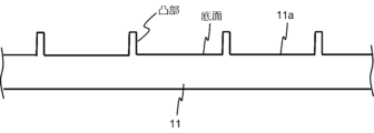
- FIG. 2 is a schematic diagram showing a cross section obtained when a conveyor belt is cut perpendicularly to the width direction.
- FIG. 3 is a side view of the spiked lattice belt, in other words, a schematic diagram showing the spiked lattice belt as viewed from the width direction.
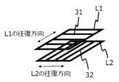
- FIG. 4 is a schematic diagram showing a grid of horizontal rods.
- 5(a) and (b) are plan views showing chopped fiber bundles, respectively.
- FIG. 6 is a schematic diagram of a self-organized carbon fiber bundle.
- 7(a) and (b) are photographs showing the appearance of the self-organized carbon fiber bundles, respectively.
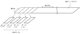
- FIG. 8 is a schematic diagram showing an example of a position where a sample is taken from a sheet prepreg to obtain a variation coefficient A described later.
- FIG. 9 is a schematic diagram showing an example of a position where a sample is taken from a sheet prepreg to obtain a variation coefficient B described later.
- Sheet prepreg manufacturing method One embodiment of the present invention relates to a method for continuously manufacturing a sheet prepreg in which a carbon fiber mat is impregnated with a thermosetting resin composition, and includes: forming the carbon fiber mat by dropping a fiber raw material containing carbon fiber bundles having a bundle length in the range of 5 mm to 100 mm onto a carrier film while running the carrier film along its longitudinal direction, and transporting the fiber raw material to a discharge end of a belt conveyor having an uneven conveying surface and an upwardly sloping portion before dropping the fiber raw material onto the carrier film, wherein the width direction of the carrier film and the width direction of the conveyor belt are parallel to each other.
- FIG. 1 shows an example of a sheet prepreg manufacturing apparatus that can be preferably used when manufacturing a sheet prepreg by the above-described manufacturing method according to the embodiment.
- a sheet prepreg manufacturing apparatus 1 is roughly divided into a fiber raw material supply section 1A and an impregnation section 1B.
- the fiber raw material supply section 1A includes a first belt conveyor 10, a scraping roller 20, a horizontal rod 30 and a second belt conveyor 40.
- the impregnation section 1B includes a first coater 50, a second coater 60, a laminator 70 and an impregnation machine 80.
- the first belt conveyor 10 is an example of a belt conveyor having an upward gradient section, and has only an upward gradient section.
- the first belt conveyor 10 may have a horizontal section on either or both the upstream and downstream sides of the upward gradient section.
- the conveying surface 11a of the conveyor belt 11 of the first belt conveyor 10, i.e., the surface on which the fiber raw material 2 is placed, is an uneven surface. This is to prevent the fiber raw material 2 to be conveyed from slipping off the conveying surface 11a of the conveyor belt 11 on the upward slope of the first belt conveyor 10.
- the conveying surface 11a of the conveyor belt 11 may be an uneven surface having a concave portion having a bottom surface and a convex portion protruding from the bottom surface, as shown in the cross-sectional view of Fig. 2.
- the proportion of the convex portions in the uneven surface in plan view is preferably 50% or less, more preferably 10% or less, in terms of area.
- the convex portion of the uneven surface may have a wall perpendicular to the bottom surface of the concave portion, and the wall may be parallel to the width direction of the conveyor belt.
- the convex portions of the uneven surface may be columnar. The columnar convex portions may be perpendicular to the bottom surface of the concave portion or may be inclined toward the running direction of the first conveyor belt.
- the conveyor belt 11 may be a spiked lattice belt.
- the first belt conveyor 10 may be a spiked lattice conveyor.
- Figure 3 shows a typical spiked lattice belt viewed from the width direction.
- the slat width is preferably 5-30 mm, and the spike length is preferably 5-20 mm.
- the surface with the spikes is the conveying surface.
- the scraping roller 20 is an example of a scraping means for scraping off a portion of the fiber raw material 2 transported by the first belt conveyor 10, and is optionally provided midway or at the top end of the upward gradient portion of the first belt conveyor 10.
- the scraping roller 20 has a rotation axis parallel to the T direction of the first belt conveyor 10 and a cylindrical portion with the rotation axis as its central axis, and a number of blades, each parallel to the rotation axis, are arranged on the outer circumferential surface of the cylindrical portion.
- the T direction of the belt conveyor means a horizontal direction that is perpendicular to the conveying direction of the belt conveyor, and usually coincides with the width direction of the conveyor belt of the belt conveyor.
- the horizontal rod 30 is an example of a dispersing means for dispersing the fiber raw material 2 dropping from the discharge end 10E of the first belt conveyor 10, and is optionally arranged below the discharge end 10E.
- the horizontal rod 30 is a rod supported so that its longitudinal direction is horizontal, and its cross-sectional shape is not limited to a circle, but may be a polygon such as a triangle, a rectangle, or a hexagon.
- a drive mechanism (not shown) causes the horizontal rod 30 to reciprocate in a horizontal plane along a direction perpendicular to its longitudinal direction.
- a grid is formed by the horizontal rods 30.
- the horizontal rods 30 are arranged at equal intervals in the same plane.
- the first lattice L1 and the second lattice L2 are arranged so as to be vertically overlapped, as shown in Fig. 4.
- the first lattice L1 which is made up of a plurality of horizontal rods 31, is arranged so that the horizontal rods 31 are perpendicular to the T direction of the first belt conveyor 10.
- the second lattice L2, which is made up of a plurality of horizontal rods 32, is arranged so that the horizontal rods 32 are parallel to the T direction of the first belt conveyor 10. Either the first lattice L1 or the second lattice L2 may be on top or on the bottom.
- the second belt conveyor 40 is a horizontal belt conveyor having a horizontal transport path, and is optionally disposed downstream of the first belt conveyor 10.
- the T direction of the second belt conveyor 40 is the same as the T direction of the first belt conveyor 10. It is preferable, but not essential, that the conveying path of the second belt conveyor 40 be horizontal. Even if the second belt conveyor 40 has a slope, it is acceptable as long as the slope is not so steep that the fiber raw material 2 on the conveyor belt 41 moves due to gravity.
- the fiber raw material 2 dropping from the discharge end 10E of the first belt conveyor 10 drops onto the second belt conveyor 40 and is transported toward its discharge end 40E.
- the belt running speed v2 of the second belt conveyor 40 is preferably equal to or lower than the belt running speed v1 of the first belt conveyor 10, and more preferably lower than the belt running speed v1 of the first belt conveyor 10.
- the discharge end 40E of the second belt conveyor 40 is disposed above the running path of the first carrier film 3 which runs along the longitudinal direction of the second belt conveyor 40.
- the fiber raw material 2 falls from the discharge end 40E of the second belt conveyor 40 onto the first carrier film 3 and forms a carbon fiber mat 5 on the first carrier film 3.
- the width direction of the first carrier film 3 is parallel to the T direction of the second belt conveyor 40. In the area where the fiber raw material 2 falls, the upper surface of the first carrier film 3 is held horizontally.
- the running speed v 3 of the first carrier film 3 is preferably equal to or lower than the belt running speed v 2 of the second belt conveyor 40 , and more preferably lower than the belt running speed v 2 of the second belt conveyor 40 .
- the fiber raw material 2 is dropped onto the first carrier film 3 from the discharge end 10E of the first belt conveyor 10 to form the carbon fiber mat 5.
- the running speed v3 of the first carrier film 3 is preferably equal to or lower than the belt running speed v1 of the first belt conveyor 10, and more preferably lower than the belt running speed v1 of the first belt conveyor 10.
- the first coater 50 is provided to apply a resin paste 4 to the upper surface of the first carrier film 3 before the carbon fiber mat 5 is formed.
- the second coater 60 is provided to apply the resin paste 7 to the second carrier film 6 .
- the laminating machine 70 is disposed upstream of the impregnation machine 80 and is provided to gradually bring the first carrier film 4 and the second carrier film 6 closer to each other and laminate them together to form a laminate 8 .
- the impregnation machine 80 is equipped with two belt conveyors, one above and one below, for sandwiching the laminate 8 between two conveyor belts and conveying it, and is also equipped with rolls for pressing the laminate 8 together with the conveyor belts.
- a fiber raw material containing carbon fiber bundles having a bundle length in the range of 5 mm to 100 mm is used as a raw material for the carbon fiber mat. Since such a collection of carbon fiber bundles is prone to a bridge phenomenon, it is difficult to supply a fixed amount using a supply device equipped with a hopper. In addition, since such a collection of carbon fiber bundles is prone to entangle with each other when compressed, it is also difficult to supply a fixed amount using a screw feeder or a vibration feeder. In the method according to the embodiment, a fixed amount of fiber raw material containing carbon fiber bundles having a bundle length within the above range is realized by using a belt conveyor having a conveyor belt with an uneven conveying surface and an upwardly inclined section.
- the method according to the embodiment is more advantageous when the fiber raw material contains carbon fiber bundles having a bundle length of 10 mm or more, and further when the fiber raw material contains carbon fiber bundles having a bundle length of 20 mm or more.
- all the carbon fiber bundles contained in the fiber raw material may have a bundle length of 100 mm or less, 90 mm or less, 80 mm or less, 70 mm or less, 60 mm or less, 50 mm or less, 40 mm or less, or 30 mm or less.
- all the carbon fiber bundles contained in the fiber raw material have a bundle length of 60 mm or less, more preferably a bundle length of 40 mm or less, and even more preferably a bundle length of 30 mm or less.
- chopped carbon fiber bundles One example of carbon fiber bundles with a bundle length of 5 to 100 mm contained in the fiber raw material is chopped carbon fiber bundles.
- Chopped carbon fiber bundles also known as carbon fiber chopped strands, are produced by cutting continuous carbon fiber bundles to a specified length between 5 mm and 100 mm.
- Chopped carbon fiber bundles usually have a flat shape.
- the planar shape of the chopped carbon fiber bundle can vary.
- the bundle length is approximately equal to the length of the carbon fiber filaments contained in the chopped carbon fiber bundle.
- the bundle length is longer than the length of the carbon fiber filaments contained in the chopped carbon fiber bundle.
- SACFB self-assembled carbon fiber bundle
- SACFBs are formed through a process in which a plurality of short carbon fibers assemble themselves into a bundle.
- the bundle length of a SACFB is generally longer than the average length of the carbon fiber filaments contained therein.
- the bundle length of a SACFB may exceed twice the length of the longest carbon fiber filament contained therein.
- the number of carbon fiber filaments contained in one SACFB (bundle size of the SACFB) is preferably within the range of 1,500 to 10,000, but is not limited thereto.
- the carbon fibers constituting the SACFB may all be non-thermally degraded carbon fibers, or may be partly non-thermally degraded carbon fibers and the remaining part thermally degraded carbon fibers.
- the carbon fibers constituting the SACFB may all be thermally degraded carbon fibers.
- Non-thermally degraded carbon fibers are typically virgin carbon fibers.
- Thermally degraded carbon fibers are typically recycled carbon fibers recovered from waste CFRP (carbon fiber reinforced plastic), and are thermally degraded in the process of pyrolyzing and removing the matrix resin.
- SACFB preferably contains only carbon fiber as a fiber component, but if there is no particular problem, it is permissible to contain fibers other than carbon fiber, such as glass fiber.
- the content of fibers other than carbon fiber in SACFB is preferably less than 10 wt%, more preferably less than 5 wt%, and even more preferably less than 1 wt%. This is because fibers other than carbon fiber are less effective as reinforcing materials for FRP than carbon fiber.
- the SACFB made of virgin carbon fiber can be manufactured, for example, by using chopped carbon fiber bundles as a raw material.
- the fiber filament length of the chopped carbon fiber bundle is preferably 5 mm or more, and may be 10 mm or more, and is preferably 60 mm or less, more preferably 40 mm or less, and even more preferably 30 mm or less, and may be 20 mm or less.
- chopped carbon bundles are unbundled to form cotton-like carbon fibers.
- the chopped carbon fiber bundles can be unbundled by putting only the chopped carbon fiber bundles into a stirring mixer such as a Henschel mixer and stirring in a dry state.
- the cotton-like carbon fibers are then mixed with a bundling liquid to spontaneously bundle the short carbon fibers that make up the cotton-like carbon fibers.
- the liquid components in the bundling liquid are evaporated and removed to obtain the SACFB. According to this method, most of the carbon fiber filaments contained in the chopped carbon fiber bundles participate in the formation of the SACFB while maintaining their length.
- the preferred liquid component contained in the bundling liquid is water.
- the strong surface tension of water strongly promotes bundling of short carbon fibers through the capillary effect.
- the amount of bundling liquid used can be, for example, 20 to 80 parts by weight per 100 parts by weight of short carbon fibers.
- Organic binders may be added to the bundling liquid as dispersoids or solutes. Sizing agents contained in the raw virgin carbon fiber bundles may remain in the SACFB while retaining their ability as organic binders.
- organic binders include, but are not limited to, epoxy resins, unsaturated polyester resins, vinyl ester resins, polyurethane resins, and polyamide resins.
- Stirring is preferable for efficient mixing in a short time.
- a powder stirrer known as a Henschel mixer can be preferably used.
- a drum mixer that rotates a container can also be used to mix the flocculent carbon fibers and the bundling liquid.
- the shape of the SACFB can be spindle-shaped, needle-shaped, wire-shaped, etc. Photographs of a spindle-shaped SACFB and a wire-shaped SACFB are shown in Figures 7(a) and (b), respectively. Wire-shaped SACFB is particularly prone to bridging and is difficult to dispense using hopper, screw or vibratory feeders, and therefore, methods according to embodiments are particularly advantageous when involving wire-shaped SACFB.
- all or a part of the virgin carbon fiber as the raw material can be replaced with recycled carbon fiber.
- Suitable examples of recycled carbon fibers are carbon fibers recovered from CFRP products formed from CF-SMC or scraps of CF-SMC.
- the above products or scraps are dry-distilled at a temperature of preferably 600° C. or higher, and then heated in an oxidizing atmosphere to, for example, 550° C. or higher, preferably 600° C. or higher, to completely pyrolyze the matrix resin, leaving behind cotton-like recycled carbon fibers.
- Chopped carbon fiber bundles with a bundle length of 60 mm or less are usually used to manufacture CF-SMC, so CFRP products made from CF-SMC and cotton-like recycled carbon fibers recovered from CF-SMC scraps have filament lengths of 60 mm or less and can be preferably used as raw materials for SACFB.
- Recycled carbon fibers are not limited to those derived from SMC.
- Recycled carbon fibers recovered from CFRP products molded using various prepregs, including UD prepregs, fabric prepregs, and tow prepregs, and recycled carbon fibers recovered from CFRP products manufactured using methods that do not use prepregs, including the RTM method, VaRTM method, filament winding method, and pultrusion method, can also be preferably used as raw materials for SACFB by cutting the filament length to 60 mm or less before, during, or after the recovery process.
- the fiber raw material used in the manufacturing method of the sheet prepreg according to the embodiment may include only chopped carbon fiber bundles, or may include only SACFB.
- the fiber raw material does not include carbon fiber filaments longer than the carbon fibers included in the chopped carbon fiber bundles.
- the fiber raw material does not include carbon fiber filaments longer than the carbon fibers included in the SACFB.
- 50 wt% or more, 60 wt% or more, 70 wt% or more, 80 wt% or more, 90 wt% or more, or 95 wt% or more of the fiber raw material may be carbon fiber bundles having a bundle length in the range of 5 mm to 100 mm.
- components other than carbon fiber bundles having a bundle length in the range of 5 mm to 100 mm that may be contained in the fiber raw material include carbon fiber bundles (SACFB or chopped carbon fiber bundles) having a bundle length of less than 5 mm, as well as carbon fiber agglomerates in which the contained carbon fibers do not form bundles.
- SACFB carbon fiber bundles
- carbon fiber agglomerates in which the contained carbon fibers do not form bundles.
- carbon fibers having a short filament length of 0.3 mm or less tend to form agglomerates without bundling when wetted with a liquid and aggregated.
- the raw fiber material may contain foreign matter that was contained in the recycled carbon fiber used as the raw material for SACFB. Examples of such foreign matter include glass fibers and metal pieces.
- Recycled carbon fibers may account for 50 wt% or more, 60 wt% or more, 70 wt% or more, 80 wt% or more, 90 wt% or more, or 95 wt% or more of the carbon fibers contained in the fiber raw material.
- all of the fibers contained in the fiber raw material, including the carbon fibers have a filament length of 50 mm or less, more preferably a filament length of 40 mm or less, and even more preferably a filament length of 30 mm or less.
- the fiber raw material 2 supplied to the lower part of the first belt conveyor 10 by a non-limiting method is transported by the first belt conveyor 10 toward the discharge end 10E, which is the end of the upward gradient portion of the first belt conveyor 10.
- the amount of the fiber raw material 2 that reaches the discharge end 10E of the first belt conveyor 10 per unit time is limited by the inclination of the upward gradient portion. This is because the amount of the fiber raw material 2 that passes through the upward gradient portion while remaining on the conveying surface 11a of the conveyor belt 11 is limited.
- the amount of the fiber raw material 2 that can remain on the conveying surface 11a of the conveyor belt 11 in the upward gradient portion is determined by the balance between the frictional force acting between the carbon fiber bundles contained in the fiber raw material 2 and gravity.
- the amount of fiber raw material 2 discharged from the discharge end 10E of the first belt conveyor 10 per unit time is constant. In other words, a fixed amount of fiber raw material 2 can be supplied to the downstream side of the first belt conveyor 10.
- the variation in the amount of fiber raw material 2 that reaches the discharge end 10E of the first belt conveyor 10 per unit time can be further reduced.
- the height of the fiber raw material 2 on the first conveyor belt 11 exceeds the distance between the scraping roller 20 and the first conveyor belt 11, part of the fiber raw material 2 is scraped off by the scraping roller 20.
- the optional horizontal rod 30 can be moved back and forth in a horizontal plane in a direction perpendicular to its longitudinal direction, allowing the fiber raw material 2 to fall evenly onto the second belt conveyor 20.
- the variation in the amount of the fiber raw material 2 transported by the second belt conveyor 40 per unit time can be smaller than the variation in the amount of the fiber raw material 2 discharged from the first belt conveyor 10 per unit time.
- the fiber raw material 2 falls from the discharge end 40E of the second belt conveyor 40 onto the first carrier film 3 running underneath, forming a carbon fiber mat 5 on the first carrier film 3.
- the variation in the amount of the fiber raw material 2 transported by the first carrier film 3 per unit time can be smaller than the variation in the amount of the fiber raw material 2 discharged from the second belt conveyor 40 per unit time.
- the amount of the fiber raw material 2 transported by the first carrier film 3 per unit time can be rephrased as the weight of the carbon fiber mat 5 per unit length along the running direction of the first carrier film 3.
- a resin paste 4 is applied to the top surface of the first carrier film 3 pulled out from the roll by a first coater 50.
- the resin paste 4 is made of a thermosetting resin composition, and may contain, as a base resin, one or more thermosetting resins preferably selected from the group consisting of vinyl ester resins (also called epoxy acrylate resins), unsaturated polyester resins, epoxy resins, and phenolic resins.
- one or more thermosetting resins preferably selected from the group consisting of vinyl ester resins (also called epoxy acrylate resins), unsaturated polyester resins, epoxy resins, and phenolic resins.
- the resin paste may also contain polymerization inhibitors, thickeners, reactive diluents, low-shrinkage agents, flame retardants, antibacterial agents, etc., as necessary.
- the viscosity of the resin paste is preferably 0.1 Pa ⁇ s or more and less than 10 Pa ⁇ s, more preferably 0.2 Pa ⁇ s or more and less than 5 Pa ⁇ s, and even more preferably 0.3 Pa ⁇ s or more and less than 1 Pa ⁇ s.
- the resin paste may be lightly warmed so that the viscosity falls within the above preferred range.
- a resin paste 7 having the same composition as the resin paste 4 is applied to one side of a second carrier film 6 using a second coater 60.
- a laminating machine 70 is used to form a laminate 8 in which the first carrier film 3 and the second carrier film 6 are laminated together with the carbon fiber mat 5 sandwiched between them, with the sides coated with the resin pastes 4 and 7 facing each other.
- the laminate 8 is pressurized by the impregnator 80, so that the carbon fiber mat 5 is impregnated with the resin pastes 4 and 7 to form an impregnated carbon fiber mat.
- the impregnated carbon fiber mat is wound up on a bobbin while sandwiched between the first carrier film 3 and the second carrier film 6.
- the impregnated carbon fiber mat wound up on the bobbin is thickened as necessary to complete the sheet prepreg. Instead of winding the impregnated carbon fiber mat up on a bobbin into a roll, it may be folded and stored in a case.
- the second belt conveyor 40 may be omitted, and the fiber raw material 2 may be dropped onto the first carrier film 3 from the discharge end 10E of the first belt conveyor 10 to form the carbon fiber mat 5.
- the length direction is parallel to the running direction of the carrier film used in the manufacture of the long sheet prepreg
- the width direction is parallel to the width direction of the carrier film
- the long sheet prepreg is transported or stored in a rolled or folded state.
- the length of the long sheet prepreg may be determined so as not to cause any trouble, and may be, for example, within the range of 5 m to 10 m, 10 m to 30 m, 30 m to 50 m, 50 m to 70 m, 70 m to 100 m, 100 m to 150 m, or 150 m to 200 m, without being limited thereto.
- the width of the long sheet prepreg can be appropriately set depending on the purpose of use, and is not limited thereto, but is usually in the range of 0.3 m to 3 m, preferably 0.5 m to 2 m, and may be in the range of 1 m to 1.5 m.
- coefficient of variation A the coefficient of variation of weight per unit length obtained from measuring the four samples. The smaller the coefficient of variation A, the smaller the variation in weight per unit length along the length of the long sheet prepreg.
- Figure 8 shows an example of the locations where four samples are taken to obtain the coefficient of variation A. Each sample is weighed, and the weight per unit length of each of the four samples is obtained by dividing the weight by the length of 0.3 m. As the example in Figure 8 shows, the four samples can be taken from near one end of the long sheet prepreg.
- the coefficient of variation A may be 10% or less, further 8% or less, further 6% or less, further 5% or less, or even 4% or less.
- the long sheet prepreg has a length of 7.2 m or more, six samples, each 1.2 m long, may be taken without any gaps in the longitudinal direction to evaluate the variation in weight per unit length along the longitudinal direction, and the coefficient of variation of weight per unit length obtained from the measurement of the six samples (hereinafter referred to as "coefficient of variation B") may be used as an index.
- Figure 9 shows an example of the locations where the six samples are taken. By dividing the weight of each sample by the length of 1.2 m, the weight per unit length of each of the six samples is obtained. As the example in Figure 9 shows, the six samples can be taken from near one end of the long sheet prepreg.
- the coefficient of variation B may be 5% or less, further 4% or less, further 3% or less, further 2% or less, or even 1% or less.
- At least a portion of the SACFB contained in the carbon fiber mat impregnated with the thermosetting resin composition may have a bundle length in the range of 10 mm or more and 100 mm or less, and may further have a bundle length in the range of 20 mm or more and 100 mm or less. All of the carbon fiber bundles contained in the carbon fiber mat impregnated with the thermosetting resin composition, including the SACFB, may have a bundle length of 100 mm or less, 90 mm or less, 80 mm or less, 70 mm or less, 60 mm or less, 50 mm or less, 40 mm or less, or 30 mm or less.
- all the carbon fiber bundles contained in the carbon fiber mat have a bundle length of 60 mm or less, more preferably a bundle length of 40 mm or less, and even more preferably a bundle length of 30 mm or less.
- the carbon fiber mat impregnated with the thermosetting resin composition may contain carbon fibers with a bundle length in the range of 5 mm to 100 mm, and 50% or more, 60% or more, 70% or more, 80% or more, 90% or more, or 95% or more of the total weight of the carbon fibers.
- the carbon fiber mat impregnated with the thermosetting resin composition may contain, in addition to SACFB having a bundle length in the range of 5 mm to 100 mm, SACFB having a bundle length of less than 5 mm, chopped carbon fiber bundles, and/or carbon fiber agglomerates in which the contained carbon fibers are not formed into bundles.
- the carbon fiber mat impregnated with the thermosetting resin composition preferably contains carbon fibers with a filament length of 5 mm or more, more preferably contains carbon fibers with a filament length of 10 mm or more, and even more preferably contains carbon fibers with a filament length of 20 mm or more. The longer the filament length, the greater the reinforcing effect of the carbon fibers.
- all of the fibers contained in the carbon fiber mat impregnated with the thermosetting resin composition, including the carbon fibers have a filament length of 50 mm or less, more preferably 40 mm or less, and even more preferably 30 mm or less.
- the carbon fibers contained in the carbon fiber mat impregnated with the thermosetting resin composition may be all recycled carbon fibers, some may be recycled carbon fibers and the remaining part may be virgin carbon fibers, or all may be virgin carbon fibers.
- the recycled carbon fibers may be those that have been thermally degraded during the recovery process.
- the carbon fiber mat impregnated with the thermosetting resin composition preferably contains only carbon fiber as a fiber component, but if there is no particular problem, it is acceptable for the mat to contain fibers other than carbon fiber, such as glass fiber.
- the content of fibers other than carbon fiber in the carbon fiber mat is preferably less than 10 wt%, more preferably less than 5 wt%, and even more preferably less than 1 wt%.
- base resins examples include vinyl ester resins (also called epoxy acrylate resins), unsaturated polyester resins, epoxy resins, and phenolic resins. Although not limited thereto, it is preferable to use a combination of vinyl ester resins and unsaturated polyester resins.
- the thermosetting resin composition preferably contains a thickener in addition to a curing agent.
- Curing agents and thickeners suitable for the above-mentioned resins exemplified as base resins are well known, and reference can be made to prior art in the field of SMC, for example.
- optional components that the thermosetting resin composition may contain include a polymerization inhibitor, a reactive diluent, a low shrinkage agent, a flame retardant, a colorant, and an antibacterial agent.
- the thermosetting resin composition contained in the long sheet prepreg may be in a thickened state due to the action of the added curing agent and/or thickener.
- the long sheet prepreg is cut to an appropriate length as required and then used to manufacture CFRP products.
- a CFRP product having a desired shape can be manufactured by cutting the long sheet prepreg into prepreg pieces, placing them in a mold, and curing them by heating while compressing them.
- the long sheet prepreg can be used as an intermediate material when molding a CFRP product using an autoclave.
- One embodiment of the present invention relates to a method for continuously and quantitatively supplying a fiber raw material including carbon fiber bundles having a bundle length in the range of 5 mm to 100 mm, and includes conveying the fiber raw material to a discharge end of a belt conveyor having a conveying surface with an uneven surface and an upwardly inclined portion.
- this supply method is used to supply a fiber raw material containing carbon fiber bundles having a bundle length in the range of 5 mm or more and 100 mm or less.
- the bundling liquids used were aqueous dispersions containing a sizing agent whose main component was polyurethane, and two types of bundling liquids were used, one with a water content of 90 wt % and the other with a water content of 78 wt %.
- the carbon fibers and the bundling liquid were mixed using a high-speed stirring mixer having a stirring tank with a capacity of 75 L (Intensive Mixer R08W, manufactured by Nippon Airich Co., Ltd.).
- the bulk product was prepared as follows:
- resin paste which is a thermosetting resin composition
- resin paste containing vinyl ester resin and unsaturated polyester resin as thermosetting resins, styrene as a reactive diluent, diphenylmethane diisocyanate as a thickener, and a radical polymerization initiator as a hardener.
- a primary composition containing all components except the thickener was prepared first, and the thickener was added to the primary composition immediately before use, so that the viscosity of the resin paste would not exceed 1 Pa ⁇ s when impregnating the carbon fiber mat.
- An inclined belt conveyor was prepared, which had a spiked lattice belt, a distance of 700 mm from the rear end to the discharge end (front end), and only an upward gradient section with a gradient angle of 67°.
- Each slat of the spiked lattice belt was 25 mm wide and 330 mm long, with a slat pitch of 27 mm.
- Each slat had spikes with a diameter of 3 mm and a length of 8 mm at the base, arranged at intervals of 16 mm along its longitudinal direction.
- Each spike was fixed to the slat so as to be inclined 50° from the normal to the conveying surface of the belt conveyor toward the conveying direction.
- the fiber raw material prepared in (1) above was supplied to the rear end of the inclined belt conveyor using a separately prepared horizontal belt conveyor.
- the release paper pulled out from the roll was run at a speed of 3 m/min so as to pass under the discharge end, which is the front end of the inclined belt conveyor.
- the release paper was held so that its surface was horizontal, and its running direction was perpendicular to the T direction of the inclined belt conveyor.
- the fiber raw material discharged from the discharge end of the inclined belt conveyor was dropped onto the release paper through two side plates, both of which were parallel to the running direction of the release paper and whose lower ends were lightly in contact with the surface of the release paper.
- the "width” here refers to the dimension perpendicular to the running direction of the release paper.
- a carbon fiber mat with a width of 0.3 m was formed on the release paper so that the length was about 1.4 m, and both ends in the longitudinal direction were removed so that the length was 1.2 m.
- a quick-drying spray adhesive was sprayed onto the carbon fiber mat on the release paper to prevent it from losing its shape.
- the amount of adhesive attached to the carbon fiber mat was 10 to 20 g/ m2 , and the effect on the weight per unit length of the sheet prepreg described below was negligible.
- PE film B was placed on top of it to obtain a laminate in which the resin paste-coated surfaces of PE film A and PE film B faced each other with the carbon fiber mat sandwiched between them.
- This laminate was immediately compressed using a roll to impregnate the carbon fiber mat with the resin paste. Thereafter, it was left at room temperature for 7 days to thicken the resin paste that had soaked into the carbon fiber mat, completing the sheet prepreg.
- the surface of the sheet prepreg was not sticky, and when the PE film A and the PE film B were peeled off from the sheet prepreg, no resin paste was found to be attached to their surfaces.
- the average weight per unit length, standard deviation, and coefficient of variation for these six sheet prepregs are calculated to be 576 g/m, 9.3 g/m, and 1.6%, respectively.
- the coefficient of variation is the standard deviation divided by the average weight.
- One of the six sheet prepregs was further cut into four prepreg pieces, each 0.3 m long and 0.3 m wide, and the weight of each of the four prepreg pieces was measured and divided by the length (0.3 m) to obtain the weight per unit length of each prepreg piece.
- the results are shown in Table 2 below.
- the average value, standard deviation and coefficient of variation of the weight per unit length among the four prepreg pieces were calculated to be 585 g/m, 5.7 g/m and 1.0%, respectively, where the coefficient of variation is the standard deviation divided by the average value.
- the other five of the six sheet prepregs were cut into four prepreg pieces, and the coefficient of variation of the weight per unit length between the four pieces was examined. As a result, the coefficient of variation was 8% for one sheet prepreg, but was 5% or less for the other four sheet prepregs.
- a method for continuously producing a sheet prepreg in which a carbon fiber mat is impregnated with a thermosetting resin composition comprising: dropping a fiber raw material containing carbon fiber bundles A having a bundle length in the range of 5 mm to 100 mm onto a first carrier film while running the first carrier film along the longitudinal direction of the first carrier film to form the carbon fiber mat; and transporting the fiber raw material to a discharge end of a first belt conveyor having a conveyor belt with an uneven transport surface and an upwardly sloping portion before dropping the fiber raw material onto the first carrier film, wherein a width direction of the first carrier film and a width direction of the conveyor belt are parallel to each other.
- [Item 20] The method according to any one of Items 1 to 19, wherein 50 wt % or more of the fiber raw material is the carbon fiber bundle A, and 60 wt % or more, 70 wt % or more, 80 wt % or more, 90 wt % or more, or 95 wt % or more of the carbon fiber bundle A may be present.
- [Item 21] The method according to any one of Items 1 to 20, wherein the carbon fiber bundle A includes chopped carbon fiber bundles.
- [Item 22] The method according to any one of Items 1 to 21, wherein the carbon fiber bundle A comprises a self-assembled carbon fiber bundle.
- [Item 23] The method according to any one of Items 1 to 20, wherein the carbon fiber bundles A include only self-assembled carbon fiber bundles.
- [Item 24] The method according to item 22 or 23, wherein the self-assembled carbon fiber bundles include wire-like carbon fiber bundles.
- [Item 25] The method according to any one of Items 22 to 24, wherein the self-assembled carbon fiber bundles comprise recycled carbon fibers.
- [Item 26] A method for continuously and quantitatively supplying a fiber raw material containing carbon fiber bundles A having a bundle length in the range of 5 mm to 100 mm, the method comprising: conveying the fiber raw material to a discharge end of a first belt conveyor having a conveyor belt with an uneven conveying surface and an upwardly sloping portion.
- [Item 30] The method according to any one of Items 26 to 29, further comprising using a scraping means to scrape off a portion of the fiber raw material conveyed by the first belt conveyor in the middle or at the top end of the upward gradient section.
- the scraping means includes a scraping roller having a rotation axis parallel to the T direction of the first belt conveyor, a cylindrical portion having the rotation axis as a central axis, and a plurality of blades disposed on the outer circumferential surface of the cylindrical portion, each of the blades being parallel to the rotation axis.
- the method according to any one of Items 26 to 31, comprising dropping the fiber raw material from the discharge end of the first belt conveyor.
- a method for producing a sheet prepreg comprising: supplying the fiber raw material onto a first carrier film running along the longitudinal direction of the first carrier film by the method according to any one of Items 26 to 45; and impregnating the carbon fiber mat with a thermosetting resin composition.
- a paste made of the thermosetting resin composition is applied to a surface of the first carrier film on which the carbon fiber mat is to be formed before the carbon fiber mat is formed.
- [Item 54] The sheet prepreg according to item 53, wherein the length of the sheet prepreg is 200 m or less.
- [Item 55] The sheet prepreg according to any one of Items 52 to 54, wherein the variation coefficient B is 0.01% or more.
- [Item 56] The sheet prepreg according to any one of Items 49 to 55, wherein the width of the sheet prepreg is within the range of 0.3 m to 3 m.
- [Item 57] The sheet prepreg according to any one of Items 49 to 56, wherein at least a portion of the self-organized carbon fiber bundles have a bundle length of 10 mm or more and may further have a bundle length of 20 mm or more.
- the carbon fiber mat contains carbon fibers in which 50% or more of the total weight is the self-organized carbon fiber bundle, and further 60% or more, 70% or more, 80% or more, 90% or more, or 95% or more may be the self-organized carbon fiber bundle.
- All of the carbon fiber bundles contained in the carbon fiber mat have a bundle length of 100 mm or less, and may further have a bundle length of 90 mm or less, 80 mm or less, 70 mm or less, 60 mm or less, 50 mm or less, 40 mm or less, or 30 mm or less, preferably 60 mm or less, more preferably 40 mm or less, and even more preferably 30 mm or less.
- the carbon fiber mat contains carbon fibers having a filament length of 5 mm or more, preferably contains carbon fibers having a filament length of 10 mm or more, and more preferably contains carbon fibers having a filament length of 20 mm or more.
- the sheet prepreg according to any one of Items 49 to 60 The sheet prepreg according to any one of Items 49 to 60.
- the thermosetting resin composition contains one or more selected from a vinyl ester resin, an unsaturated polyester resin, an epoxy resin, and a phenol resin.
- the sheet prepreg produced using the method according to the embodiment can be used as an intermediate material when manufacturing CFRP products using, for example, a compression molding method.
- CFRP products have a wide range of uses, including parts used in aircraft, automobiles, ships, and other types of transportation equipment, as well as sporting goods and leisure goods.
- Sheet prepreg manufacturing apparatus 1A Fiber raw material supply section 1B Impregnation section 10 First belt conveyor 11 Conveyor belt 11a Transport surface 20 Scraping roller 30 Horizontal rod 40 Second belt conveyor 41 Conveyor belt 50 First coater 60 Second coater 70 Laminating machine 80 Impregnation machine
Landscapes
- Engineering & Computer Science (AREA)
- Mechanical Engineering (AREA)
- Chemical & Material Sciences (AREA)
- Composite Materials (AREA)
- Textile Engineering (AREA)
- Reinforced Plastic Materials (AREA)
Priority Applications (4)
| Application Number | Priority Date | Filing Date | Title |
|---|---|---|---|
| JP2024564273A JPWO2024128010A1 (https=) | 2022-12-16 | 2023-11-30 | |
| EP23903300.4A EP4635701A4 (en) | 2022-12-16 | 2023-11-30 | PROCESS FOR PRODUCING SHEET PREPRESS, PROCESS FOR SUPPLYING FIBROUS RAW MATERIAL, AND SHEET PREPRESS |
| CN202380074740.7A CN120112400A (zh) | 2022-12-16 | 2023-11-30 | 片状预浸料的制造方法、纤维原料的供给方法以及片状预浸料 |
| US19/229,015 US20250346005A1 (en) | 2022-12-16 | 2025-06-05 | Method for producing sheet prepreg, method for supplying fiber raw material, and sheet prepreg |
Applications Claiming Priority (2)
| Application Number | Priority Date | Filing Date | Title |
|---|---|---|---|
| JP2022-200806 | 2022-12-16 | ||
| JP2022200806 | 2022-12-16 |
Related Child Applications (1)
| Application Number | Title | Priority Date | Filing Date |
|---|---|---|---|
| US19/229,015 Continuation US20250346005A1 (en) | 2022-12-16 | 2025-06-05 | Method for producing sheet prepreg, method for supplying fiber raw material, and sheet prepreg |
Publications (1)
| Publication Number | Publication Date |
|---|---|
| WO2024128010A1 true WO2024128010A1 (ja) | 2024-06-20 |
Family
ID=91484853
Family Applications (1)
| Application Number | Title | Priority Date | Filing Date |
|---|---|---|---|
| PCT/JP2023/042889 Ceased WO2024128010A1 (ja) | 2022-12-16 | 2023-11-30 | シートプリプレグの製造方法、繊維原料の供給方法およびシートプリプレグ |
Country Status (5)
| Country | Link |
|---|---|
| US (1) | US20250346005A1 (https=) |
| EP (1) | EP4635701A4 (https=) |
| JP (1) | JPWO2024128010A1 (https=) |
| CN (1) | CN120112400A (https=) |
| WO (1) | WO2024128010A1 (https=) |
Citations (10)
| Publication number | Priority date | Publication date | Assignee | Title |
|---|---|---|---|---|
| JPH1163218A (ja) | 1997-08-27 | 1999-03-05 | Yanmar Diesel Engine Co Ltd | 電子制御式hst装置 |
| JP2008284729A (ja) * | 2007-05-16 | 2008-11-27 | Hekisa Chemical:Kk | 繊維含有樹脂造粒物及びその製造方法 |
| WO2012086682A1 (ja) * | 2010-12-24 | 2012-06-28 | 東レ株式会社 | 炭素繊維集合体の製造方法および炭素繊維強化プラスチックの製造方法 |
| JP2017128705A (ja) * | 2016-01-22 | 2017-07-27 | 阿波製紙株式会社 | 炭素繊維シート材、プリプレグ、積層体、成形体及びそれらの製造方法 |
| JP2018126975A (ja) * | 2017-02-10 | 2018-08-16 | 三菱ケミカル株式会社 | シートモールディングコンパウンドの製造方法及びシートモールディングコンパウンドの製造装置 |
| US20190118412A1 (en) * | 2016-06-03 | 2019-04-25 | Magna Exteriors Inc. | Method to uniformly debundle and evenly distribute high fiber count carbon tow |
| WO2021010084A1 (ja) * | 2019-07-16 | 2021-01-21 | 東レ株式会社 | 繊維散布ブースおよびそれを用いた強化繊維マット製造装置 |
| CN214114285U (zh) * | 2020-12-31 | 2021-09-03 | 常州市新创智能科技有限公司 | 一种碳纤维短切纱分撒平铺设备 |
| WO2022265099A1 (ja) * | 2021-06-18 | 2022-12-22 | 三菱ケミカル株式会社 | 自己組織化炭素繊維束及びその製造方法と、プリプレグ及びその製造方法 |
| WO2023100702A1 (ja) * | 2021-12-01 | 2023-06-08 | 三菱ケミカル株式会社 | シートプリプレグの製造方法 |
-
2023
- 2023-11-30 JP JP2024564273A patent/JPWO2024128010A1/ja active Pending
- 2023-11-30 CN CN202380074740.7A patent/CN120112400A/zh active Pending
- 2023-11-30 WO PCT/JP2023/042889 patent/WO2024128010A1/ja not_active Ceased
- 2023-11-30 EP EP23903300.4A patent/EP4635701A4/en active Pending
-
2025
- 2025-06-05 US US19/229,015 patent/US20250346005A1/en active Pending
Patent Citations (10)
| Publication number | Priority date | Publication date | Assignee | Title |
|---|---|---|---|---|
| JPH1163218A (ja) | 1997-08-27 | 1999-03-05 | Yanmar Diesel Engine Co Ltd | 電子制御式hst装置 |
| JP2008284729A (ja) * | 2007-05-16 | 2008-11-27 | Hekisa Chemical:Kk | 繊維含有樹脂造粒物及びその製造方法 |
| WO2012086682A1 (ja) * | 2010-12-24 | 2012-06-28 | 東レ株式会社 | 炭素繊維集合体の製造方法および炭素繊維強化プラスチックの製造方法 |
| JP2017128705A (ja) * | 2016-01-22 | 2017-07-27 | 阿波製紙株式会社 | 炭素繊維シート材、プリプレグ、積層体、成形体及びそれらの製造方法 |
| US20190118412A1 (en) * | 2016-06-03 | 2019-04-25 | Magna Exteriors Inc. | Method to uniformly debundle and evenly distribute high fiber count carbon tow |
| JP2018126975A (ja) * | 2017-02-10 | 2018-08-16 | 三菱ケミカル株式会社 | シートモールディングコンパウンドの製造方法及びシートモールディングコンパウンドの製造装置 |
| WO2021010084A1 (ja) * | 2019-07-16 | 2021-01-21 | 東レ株式会社 | 繊維散布ブースおよびそれを用いた強化繊維マット製造装置 |
| CN214114285U (zh) * | 2020-12-31 | 2021-09-03 | 常州市新创智能科技有限公司 | 一种碳纤维短切纱分撒平铺设备 |
| WO2022265099A1 (ja) * | 2021-06-18 | 2022-12-22 | 三菱ケミカル株式会社 | 自己組織化炭素繊維束及びその製造方法と、プリプレグ及びその製造方法 |
| WO2023100702A1 (ja) * | 2021-12-01 | 2023-06-08 | 三菱ケミカル株式会社 | シートプリプレグの製造方法 |
Also Published As
| Publication number | Publication date |
|---|---|
| EP4635701A4 (en) | 2026-04-08 |
| EP4635701A1 (en) | 2025-10-22 |
| CN120112400A (zh) | 2025-06-06 |
| JPWO2024128010A1 (https=) | 2024-06-20 |
| US20250346005A1 (en) | 2025-11-13 |
Similar Documents
| Publication | Publication Date | Title |
|---|---|---|
| JP6857165B2 (ja) | 熱可塑性安定化材料を有する広幅物のリサイクリング | |
| US9931810B2 (en) | Intermediate material of constant width for fabricating composite parts by a direct process | |
| US5565049A (en) | Method of making mats of chopped fibrous material | |
| CN103764890B (zh) | 经固化的纤维束、其制造方法、其用途和由其获得的成型体 | |
| EP3485075B1 (en) | Carbon fiber random mat and carbon fiber composite material | |
| JPH0641534B2 (ja) | 繊維強化熱可塑性プリプレグ | |
| JP7400807B2 (ja) | 繊維強化樹脂成形材料成形品およびその製造方法 | |
| JP6863478B2 (ja) | 炭素繊維束、炭素繊維束の製造方法、及びシートモールディングコンパウンドの製造方法 | |
| EP4122666B1 (en) | Smc manufacturing method | |
| CN112955294B (zh) | 纤维增强树脂成型材料及其成型品 | |
| CN115461204A (zh) | Smc的制造方法 | |
| KR102253926B1 (ko) | 부분 분섬 섬유 다발의 제조 방법과 부분 분섬 섬유 다발, 및 부분 분섬 섬유 다발을 사용한 섬유 강화 수지 성형 재료와 그의 제조 방법 | |
| WO2024128010A1 (ja) | シートプリプレグの製造方法、繊維原料の供給方法およびシートプリプレグ | |
| EP2054206A1 (de) | Verfahren zur herstellung von prepregs | |
| US20030107148A1 (en) | Methods of randomly dispersing chopped carbon fiber and consolidating the materials together to make a fiber reinforcement mat | |
| WO2014057655A1 (ja) | 繊維ボード及びその製造方法 | |
| JP2025010548A (ja) | シートプリプレグの製造方法及びシートプリプレグ製造装置 | |
| JPWO2024128010A5 (https=) | ||
| JPH0586210A (ja) | 繊維強化熱可塑性樹脂シートの製造方法 | |
| WO2014065161A1 (ja) | スタンパブルシート | |
| WO2025158686A1 (ja) | 炭素繊維を含有する粒体成形材料を供給する方法、炭素繊維を含有する樹脂シートを製造する方法、および、炭素繊維を含有する樹脂シートを製造するための装置 | |
| DE3442558A1 (de) | Walzen- bzw. rohrartiger formkoerper sowie verfahren und vorrichtung zur herstellung desselben | |
| JP6273596B2 (ja) | 繊維ボードの製造方法 | |
| WO2025081288A1 (en) | Reinforcement material with natural fibers and preparation method thereof | |
| WO2022202981A1 (ja) | 短繊維強化プリプレグシート、および短繊維強化プリプレグシートの製造方法 |
Legal Events
| Date | Code | Title | Description |
|---|---|---|---|
| 121 | Ep: the epo has been informed by wipo that ep was designated in this application |
Ref document number: 23903300 Country of ref document: EP Kind code of ref document: A1 |
|
| WWE | Wipo information: entry into national phase |
Ref document number: 2024564273 Country of ref document: JP |
|
| WWE | Wipo information: entry into national phase |
Ref document number: 202380074740.7 Country of ref document: CN |
|
| WWP | Wipo information: published in national office |
Ref document number: 202380074740.7 Country of ref document: CN |
|
| WWE | Wipo information: entry into national phase |
Ref document number: 2023903300 Country of ref document: EP |
|
| NENP | Non-entry into the national phase |
Ref country code: DE |
|
| ENP | Entry into the national phase |
Ref document number: 2023903300 Country of ref document: EP Effective date: 20250716 |
|
| WWP | Wipo information: published in national office |
Ref document number: 2023903300 Country of ref document: EP |